FRAME
J1.6-2.0XMT (J30-40ZT) [J160]
PART NO. 1554626
100 SRM 1073

SAFETY PRECAUTIONS
MAINTENANCE AND REPAIR
• When lifting parts or assemblies, make sure all slings, chains, or cables are correctly
fastened, and that the load being lifted is balanced. Make sure the crane, cables, and
chains have the capacity to support the weight of the load.
• Do not lift heavy parts by hand, use a lifting mechanism.
• Wear safety glasses.
• DISCONNECT THE BATTERY CONNECTOR before doing any maintenance or repair
on electric lift trucks. Disconnect the battery ground cable on internal combustion lift
trucks.
• Always use correct blocks to prevent the unit from rolling or falling. See HOW TO PUT
THE LIFT TRUCK ON BLOCKS in the Operating Manual or the Periodic Mainte-
nance section.
• Keep the unit clean and the working area clean and orderly.
• Use the correct tools for the job.
• Keep the tools clean and in good condition.
• Always use HYSTER APPROVED parts when making repairs. Replacement parts
must meet or exceed the specifications of the original equipment manufacturer.
• Make sure all nuts, bolts, snap rings, and other fastening devices are removed before
using force to remove parts.
• Always fasten a DO NOT OPERATE tag to the controls of the unit when making repairs,
or if the unit needs repairs.
• Be sure to follow the WARNING and CAUTION notes in the instructions.
• Gasoline, Liquid Petroleum Gas (LPG), Compressed Natural Gas (CNG), and Diesel fuel
are flammable. Be sure to follow the necessary safety precautions when handling these
fuels and when working on these fuel systems.
• Batteries generate flammable gas when they are being charged. Keep fire and sparks
away from the area. Make sure the area is well ventilated.
NOTE: The following symbols and words indicate safety information in this
manual:
WARNING
Indicates a condition that can cause immediate death or injury!
CAUTION
Indicates a condition that can cause property damage!

Frame
Table of Contents
TABLE OF CONTENTS
Introduction........................................................................................................................................................
General ...........................................................................................................................................................
Description of Operation ...............................................................................................................................
Discharging the Capacitors...........................................................................................................................
Covers and Floor Plates.....................................................................................................................................
Overhead Guard Repair ....................................................................................................................................
Remove ...........................................................................................................................................................
Install .............................................................................................................................................................
Hood and Seat Assembly ...................................................................................................................................
Remove ...........................................................................................................................................................
Install .............................................................................................................................................................
Counterweight....................................................................................................................................................
Remove ...........................................................................................................................................................
Install .............................................................................................................................................................
Safety Labels ......................................................................................................................................................
Painting Instructions.........................................................................................................................................
This section is for the following models:
J1.6-2.0XMT (J30-40ZT) [J160]
©2004 HYSTER COMPANY
i

"THE
QUALITY
KEEPERS"
HYSTER
APPROVED
PARTS
100 SRM 1073
Introduction
Introduction
GENERAL
This section contains a description and the service
procedures for the parts of the frame. These parts in-
clude the frame, counterweight assembly, overhead
guard, hood and seat assembly, access panels, and
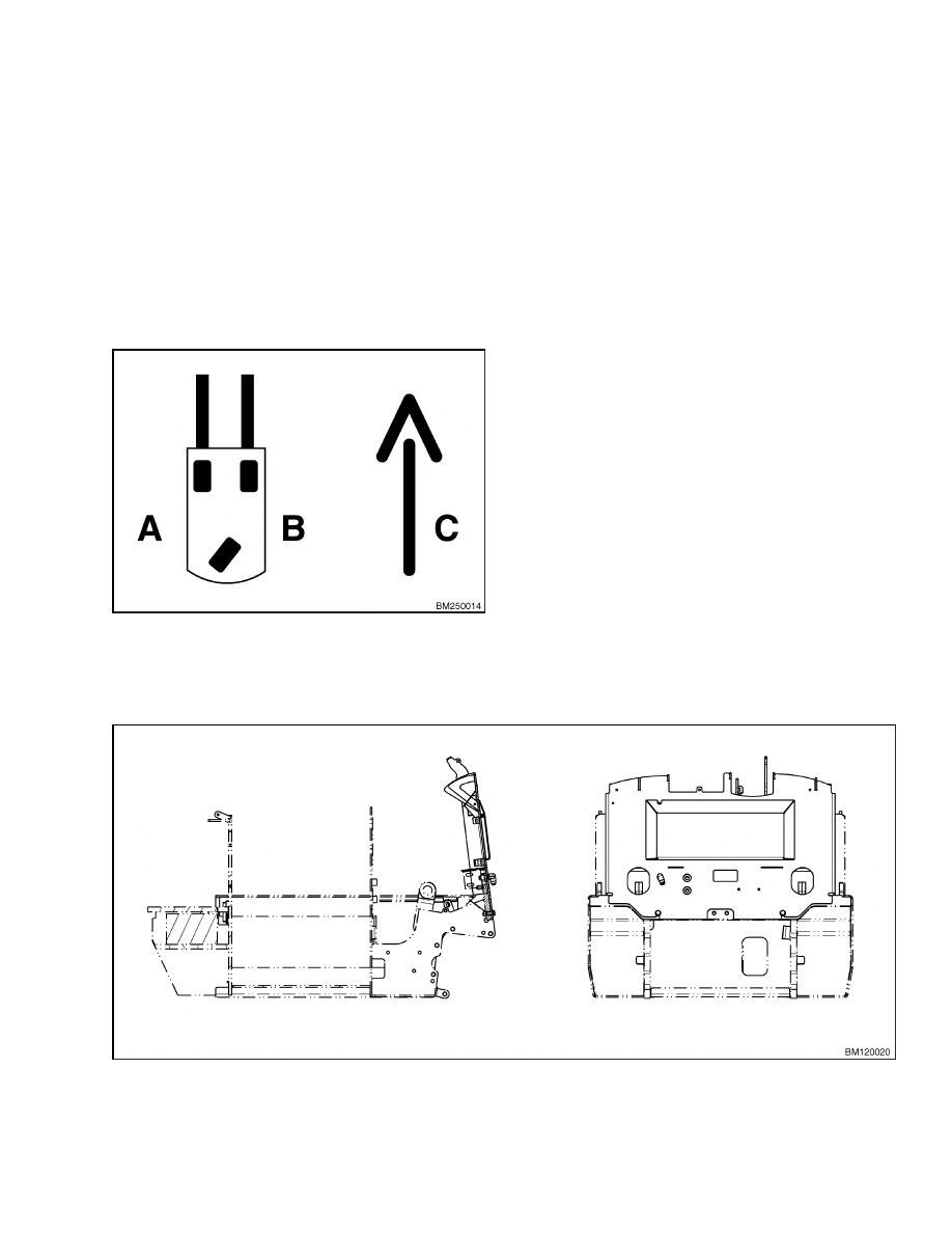
labels. Throughout this section, forward will refer to
travel in the direction of the forks and left and right
will be determined by an operator sitting in the seat
facing forward. See Figure 1.
A. LEFT SIDE
B. RIGHT SIDE
C. FORWARD TRAVEL
Figure 1. Truck Orientation
DESCRIPTION OF OPERATION
The frame is a single weldment with mounts for the
counterweight, overhead guard, mast, steering sys-
tem, hydraulic system and transaxles. See Figure 2.
The battery cover opens on hinges to give access to
the battery compartment. The weight of the battery
is a major part of the counterweight system on an
electric lift truck. A slot in the overhead guard per-
mits removal of the battery without removing the
overhead guard. Spacers may be added under the
battery as required on some models.
Each model of lift truck has a cast-iron counter-
weight with a weight necessary for the indicated
capacity. An access panel on the top/rear of the coun-
terweight gives access to the electronic controllers.
The hydraulic pump and motor, steering pump and
motor, drive motors and transaxles, and hydraulic
tank are under the floor plates in the operator com-
partment. The floor plates are held in position by
tabs and can be removed to give access to components
underneath.
The hydraulic control valve is fastened to the front
of the battery compartment. Three covers protect the
control valve and control linkage. The covers are fas-
tened in position by machine screws. The top covers
are locked in place and must be released and swung
open before attempting to open the battery cover.
Figure 2. Frame
1

Introduction
100 SRM 1073
DISCHARGING THE CAPACITORS
WARNING
Do not make repairs or adjustments unless you
have both authorization and training. Repairs
and adjustments that are not correct can cre-
ate dangerous operating conditions. Do not op-
erate a lift truck that needs repairs. Report
the need for repairs to your supervisor imme-
diately. If repair is necessary, attach a DO NOT
OPERATE tag on the steering wheel. Remove
the key from the key switch.
WARNING
Disconnect the battery before opening the
drive unit compartment cover or inspecting or
repairing the electrical system. If a tool causes
a short circuit, the high current flow from the
battery can cause personal injury or property
damage.
WARNING
Some checks and adjustments are done with
the battery connected.
Do not connect the
battery until the procedure tells you to do so.
Never have any metal on your fingers, arms,
or neck. Metal items can accidentally make an
electrical connection and cause injury.
WARNING
Before performing any tests or adjustments,
block the lift truck to prevent unexpected
movement.
WARNING
The capacitor in the transistor controller(s)
can hold an electrical charge after the battery
is disconnected. To prevent an electrical shock
and personal injury, discharge the capacitor(s)
before inspecting or repairing any component
in the drive unit compartment.
Wear safety
glasses.
Make certain that the battery has
been disconnected.
CAUTION
To avoid controller damage, always disconnect
the battery, discharge the capacitor(s), and
never put power to the controller while any
power wires are disconnected.
Never short
any controller terminal or motor terminal to
the battery. Make sure to use proper proce-
dure when servicing the controller.
1.
Turn key switch to OFF position and disconnect
the battery.
Block load wheels to prevent lift
truck from moving.
2.
Open the electrical compartment at the rear of
the truck.
a. Remove the two screws securing the electri-
cal compartment door closed.
b. Tilt the door back on its hinges to open the
compartment.
WARNING
DO NOT short across the motor controller ter-
minals with a screwdriver or jumper wire.
NOTE: Some lift trucks are equipped with a premium
controller, which controls the hydraulic motor as well
as the traction motors.
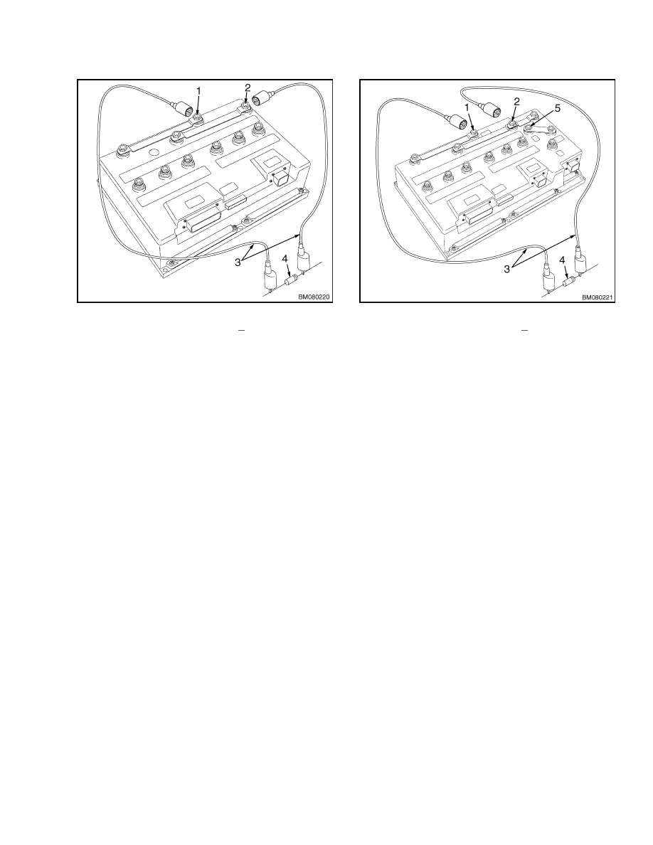
3.
Discharge the capacitor in the controller by con-
necting a 200-ohm, 2-watt resistor across the
controller’s BT+ and B
terminals for 10 seconds
using insulated jumper wires. See Figure 3.
4.
On the premium controller, also connect the 200-
ohm, 2-watt resistor across the controller’s P+
and B
terminals for 10 seconds using insulated
jumper wires. See Figure 4.
5.
Remove the 200-ohm, 2-watt resistor before re-
connecting the battery.
2
100 SRM 1073
Covers and Floor Plates
1.
POSITIVE CONNECTION (BT+)
2.
NEGATIVE CONNECTION (B )
3.
INSULATED JUMPER WIRES
4.
200-OHM, 2-WATT RESISTOR
Figure 3. Discharging the Capacitors
(Standard)
1.
POSITIVE CONNECTION (BT+)
2.
NEGATIVE CONNECTION (B )
3.
INSULATED JUMPER WIRES
4.
200-OHM, 2-WATT RESISTOR
5.
POSITIVE CONNECTION (P+)
Figure 4. Discharging the Capacitors
(Premium)
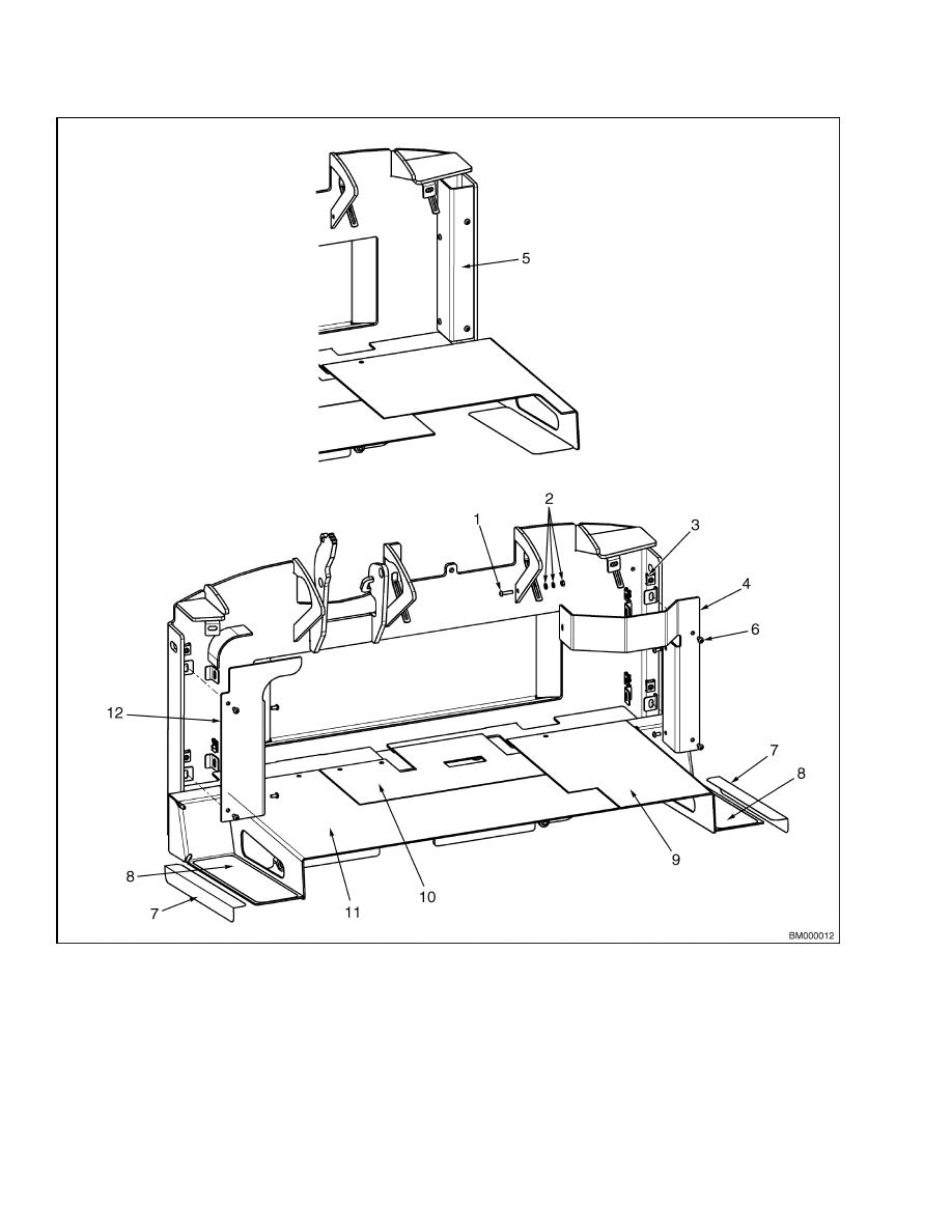
Covers and Floor Plates
Many system components, such as hydraulic hoses,
pump and motor, and wiring harnesses, are located
in the area around and under the operator compart-
ment. Various covers and floor plates provide access
to these components during service and securely
cover these areas during normal operation.
See
3
Covers and Floor Plates
100 SRM 1073
1.
CAPSCREW
2.
ATTACHING HARDWARE
3.
CLIP NUT
4.
HARNESS COVER (ELECTRIC VALVE)
5.
HARNESS COVER (MANUAL VALVE)
6.
CAPSCREW
7.
ANTI-SLIP PAD
8.
ANTI-SLIP PAD
9.
RIGHT FLOOR PLATE
10. CENTER FLOOR PLATE
11. LEFT FLOOR PLATE
12. HOSE COVER
Figure 5. Covers and Floor Plates
4
100 SRM 1073
Overhead Guard Repair
Overhead Guard Repair
WARNING
The overhead guard is part of the operator pro-
tection system. Do not operate the lift truck
without the overhead guard correctly fastened
to the lift truck.
The overhead guard is designed to provide protection
to the operator from falling objects and in the event
of a tip over. A high visibility design allows for an
unobstructed view while maintaining structural in-
tegrity. Removal of the battery is simplified by the
slot in the overhead guard. This provides access to
the battery with an overhead lifting device without
removing the overhead guard.
REMOVE
WARNING
The overhead guard is heavy. Make sure the
sling, chain, eyebolts, and crane or lifting
device have the capacity to lift the overhead
guard.
1.
Remove the six capscrews, washers, and nuts
that secure the supports of the overhead guard
to the counterweight and cowl. See Figure 6.
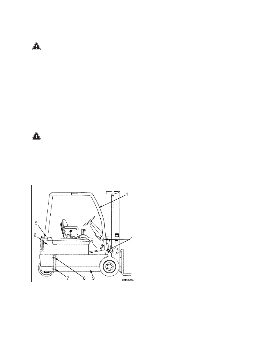
Figure 6. Overhead Guard Mounting
Legend for Figure 6
1.
OVERHEAD GUARD
2.
COUNTERWEIGHT
3.
FRAME
4.
CAPSCREWS (4) FRONT
5.
CAPSCREWS (2) REAR
6.
CAPSCREWS (2) UPPER
7.
CAPSCREWS (2) LOWER
2.
Use an overhead lifting device and sling to lift
the overhead guard until it is just higher than
the counterweight mounts.
NOTE: Tie a cord around the wires from each post
of the overhead guard before removal. Remove the
wires from the post. Untie the cord from the wires
and tape each end of the cord to the overhead guard
where it enters the post. Use the cord to pull the
wires up through the post when installing the over-
head guard.
3.
Tag and disconnect the wiring from each post of
the overhead guard. Carefully remove the wiring
if necessary.
4.
Completely remove the overhead guard from the
lift truck.
INSTALL
1.
Position overhead guard just above mounts on
the counterweight and cowl using an overhead
lifting device and sling.
2.
Route the wires through each overhead guard
post and install to lights as removed.
3.
Lower overhead guard supports onto the mounts.
4.
Install and tighten six capscrews, washers, and
nuts securing overhead guard to the lift truck.
Tighten capscrews to 134 N•m (99 lbf ft).
5.
Remove sling and overhead guard.
5
Hood and Seat Assembly
100 SRM 1073
Hood and Seat Assembly
The hood is the platform for the seat assembly and
is located above the battery. It functions as a battery
restraint that completely covers the battery compart-
ment. See Figure 7. Its function as the battery re-
straint, when correctly locked to the frame, is to hold
the battery in the battery compartment if an accident
causes the lift truck to tip over. The hood is com-
posed of a plastic cover attached to a metal frame.
Two hinges at the back of the hood attach it to the
frame. A sliding latch mechanism on the front of the
hood locks the hood closed during operation. A dou-
ble-dampened, gas-controlled strut holds the hood in
the open position.
Opening the sliding latch unlocks the hood from the
frame so the hood can be raised to access the bat-
tery. See Figure 8. The latch can only be accessed
after releasing and raising the hydraulic levers and
linkage assembly up and out of the way. A button on
each side of the assembly can be pressed to release
the assembly so it can be moved clear of the hood on
its hinged bracket. The latch must be in good condi-
tion and properly secured before the lift truck can be
operated. If the latch does not lock the hood in the
closed position, the hydraulic levers and linkage as-
sembly will not lock into position and the lift truck
will not operate.
A large, red button switch is mounted on the hood at
the right side of the seat assembly. This switch is an
emergency battery disconnect that allows the opera-
tor to quickly disconnect the battery while seated on
the lift truck in case of an emergency.
The seat assembly slides on seat rails that are fas-
tened to the hood by four capscrews. A lever at the
left front side of the base controls the adjustment of
the seat to the forward and backward positions. Op-
tional seats are available in cloth or vinyl with fea-
tures such as semi-suspension, full suspension, and
limited swivel. All seats have a seat switch installed
in the bottom cushion that senses operator presence.
When the operator is not on the seat, the seat switch
opens and interrupts the controller stopping opera-
tion of the lift truck.
The hood, seat belt, hip restraint brackets, seat, and
seat mount are all parts of the operator restraint sys-
tem. Checks and adjustments for the operator re-
straint system are described in the Operating Man-
ual and the section Periodic Maintenance 8000
SRM 1079.
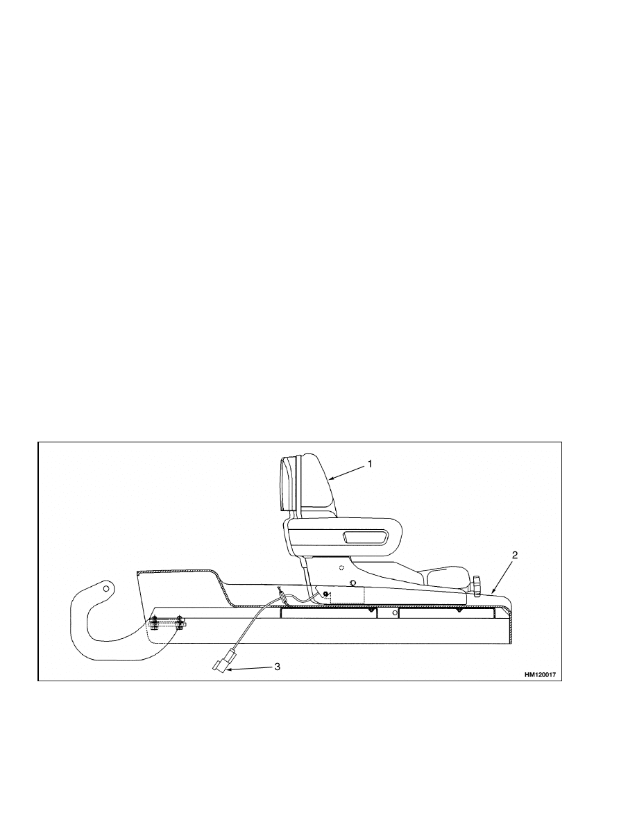
1.
SEAT
2.
HOOD
3.
SEAT SWITCH CONNECTOR
Figure 7. Hood and Seat Assembly
6
100 SRM 1073
Hood and Seat Assembly
To raise the hood and seat assembly, move the seat
to the rear of the hood if necessary. Move the steer-
ing column to the most forward position. Release
and raise the hydraulic levers and linkage. Open the
latch mechanism and raise the hood.
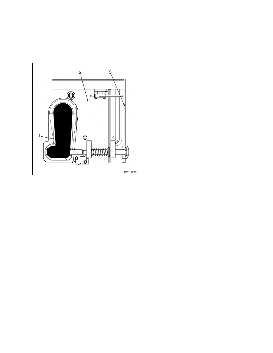
1.
SLIDING LATCH MECHANISM
2.
HOOD
3.
FRAME
Figure 8. Latch Mechanism
REMOVE
1.
Disconnect the battery connector.
2.
Tag and disconnect the electrical connectors
to the emergency battery disconnect, the seat
switch, and the hood and latch position switches.
Remove hood and latch switches if necessary.
3.
Remove the emergency battery disconnect switch
and hood and latch position switches, if neces-
sary.
NOTE: The seat assembly does not have to be re-
moved from the hood to remove the hood from the
lift truck. To remove the seat, remove the four cap-
screws that fasten the seat base to the hood. Lift the
seat assembly from the hood. If the seat is not being
removed, raise the hood.
4.
Remove the stop screws from the seat assembly,
hold the slide function lever in the open position,
and slide the seat from the mounting bracket.
Remove mounting bracket from hood if neces-
sary.
5.
Disconnect the double-dampened, gas-controlled
struts by removing the locking clips retaining the
struts to the hood and the capscrews securing the
lower ends to frame. Move the hood to the closed
position.
6.
Remove capscrews securing hood mounting
brackets to hood and lift hood from truck.
7.
Slide hood mounting brackets from studs on
counterweight brackets.
Replace bushings if
necessary.
8.
Remove the capscrews, washers, and nuts retain-
ing the hood cover to its metal frame if necessary.
INSTALL
1.
Install the capscrews, washers, and nuts to se-
cure the hood cover to its metal frame.
2.
Install new bushings to mounting brackets if nec-
essary. Slide hood mounting brackets onto coun-
terweight bracket studs as removed.
3.
With the aid of an assistant or overhead lifting
device and sling, position the hood on the hinges
and install the four capscrews. Tighten snugly
but do not torque at this time. Place the hood in
the closed position.
4.
Open and close the hood to check for proper
clearance. The minimum clearance between the
hood and the front plate of the frame is 3.5 mm
(0.14 in.). Check to ensure the proper clearance.
5.
Tighten the capscrews to 86 N•m (63 lbf ft).
6.
Raise the hood. Align and install the gas-filled
struts and install the locking clips to retain the
struts to the hood and install capscrews to secure
the lower ends to frame.
7.
If the seat assembly has been removed, in-
stall the mounting bracket to the hood using
capscrews, washers, and nuts. Hold the slide
function lever in the open position and slide the
7
Counterweight
100 SRM 1073
seat into mounting bracket tracks. Release the
lever and install the stop screws.
8.
Install hood and latch switches and emergency
battery disconnect switch, if removed, and adjust
as necessary.
9.
Connect the wiring harnesses to the seat switch,
emergency battery disconnect, and the hood and
latch position switches.
10. Close the hood. Make certain that the locking
mechanism to retain the hood is properly en-
gaged. Close the hydraulic linkage and covers.
11. Connect the battery connector.
Counterweight
WARNING
Do not operate the lift truck if the capscrews
for the counterweight are not installed. When
the capscrews are removed, the counterweight
can fall from the lift truck.
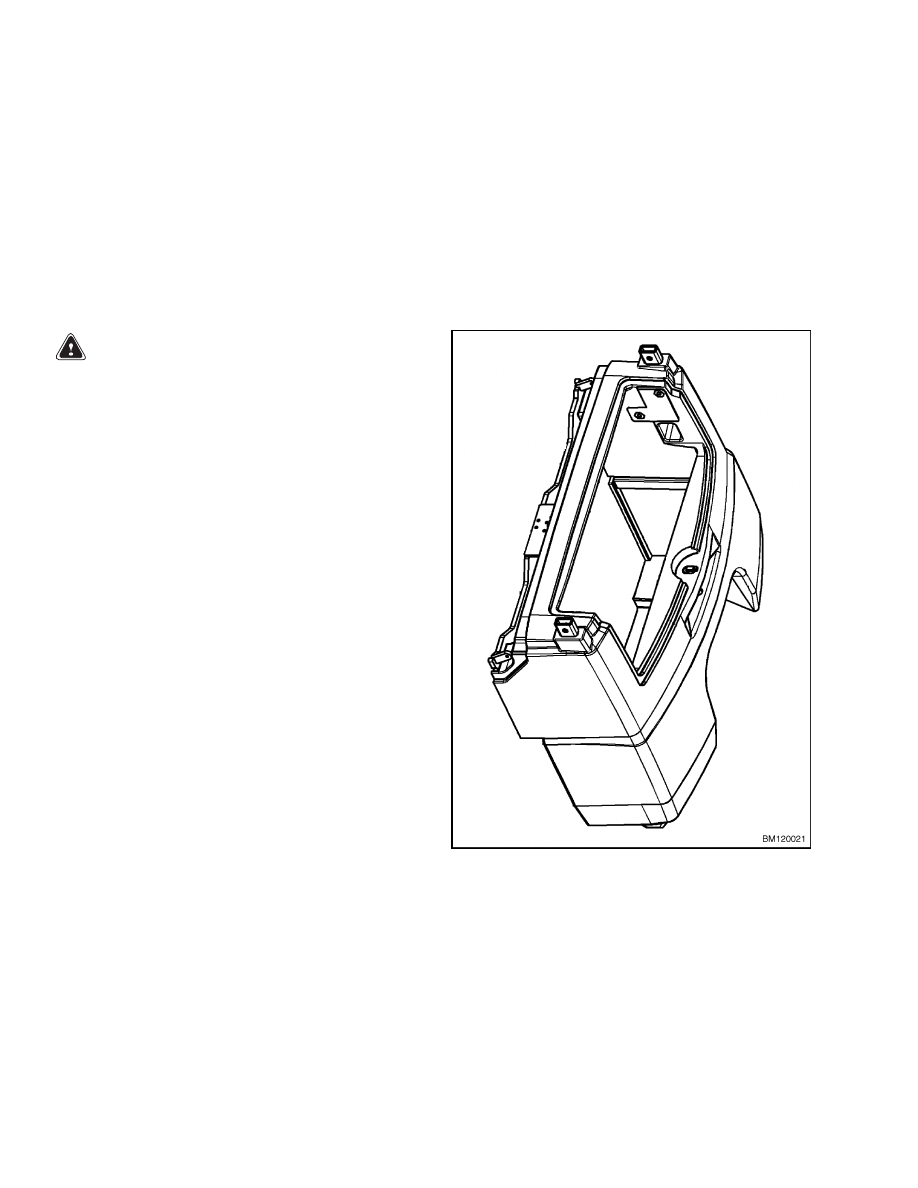
A one-piece, cast iron counterweight is used to off-
set the weight of the load. See Figure 9. The coun-
terweight is mounted to the rear of the truck using
four mounting bolts and is supported by a protruding
flange of the frame. See Figure 9. A compartment
space, accessed by a hinged door, has been designed
into the center of the counterweight to house the elec-
trical connections.
A battery platform is used to support the battery on
the lift truck frame. The battery platform also serves
as part of the counterweight system and requires the
use of an overhead lifting device for removal or in-
stallation. Be sure to replace the same battery plat-
form, or one of equal weight, if the platform must be
removed.
REMOVE
1.
Remove battery. See the section Periodic Main-
tenance 8000 SRM 1079 for instructions on re-
moving the battery.
NOTE: It may not be necessary to remove the battery
platform. Perform only the steps necessary to com-
plete the required service.
2.
Remove battery platform if necessary:
a. Remove the battery spacer and the acid tray
positioned on top of the battery platform.
b. Remove the two capscrews, washers, and
nuts retaining the platform to the frame.
c.
Use a lifting device to lift the platform out of
the lift truck.
Figure 9. Counterweight
3.
Remove overhead guard. See Overhead Guard
Repair.
4.
Remove the two large screws securing the elec-
trical compartment access door in the closed po-
sition and pull open the door.
5.
Discharge the capacitor(s). See Discharging the
Capacitors.
8
100 SRM 1073
Counterweight
NOTE: Make note of wires and cable routing for
proper reassembly.
6.
Remove socket head screws and detach the con-
troller panel from the electrical compartment ac-
cess door. Remove wire ties securing wires and
cables to the door hinge mechanism.
7.
Remove the electrical compartment access door
and hinges if necessary.
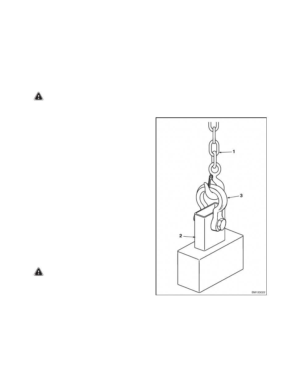
WARNING
The counterweight is very heavy. Make sure
the chains, eyebolts, and overhead lifting
device have the capacity to lift the counter-
weight.
8.
Install a clevis on each of the overhead guard
mounts. See Figure 10. Install tempered, grade
8 bolts and nuts or the proper pins for each cle-
vis. Attach a chain to each clevis. Use an over-
head lifting device to hold the weight of the coun-
terweight. Make sure the sling, chain, eyebolts,
and overhead lifting device have the capacity to
lift the counterweight.
9.
Remove the four M20 × 2.5 × 60 capscrews and
hardened flat washers that hold the counter-
weight to the frame. Four capscrews hold the
counterweight to the frame from the inside and
can be accessed from the battery compartment.
Two of the capscrews are located at the bottom
of the counterweight, while the other two are
located approximately in the center of the coun-
terweight. The nuts for the capscrews are cast
in the counterweight. Refer to Figure 6.
10. Use the overhead lifting device to lift the coun-
terweight off the mounting flange and away from
the frame. See Figure 9.
INSTALL
WARNING
The counterweight is very heavy. Make sure
the chains, eyebolts, and overhead lifting
device have the capacity to lift the counter-
weight.
1.
Use an overhead lifting device to lift the counter-
weight into position. See Remove, Step 8. Some
assistance will be required to align the mount-
ing holes in the counterweight with those in the
frame.
2.
Install the four capscrews and hardened flat
washers that hold the counterweight to the
frame.
Tighten the capscrews to 435 N•m
(321 lbf ft).
3.
Disconnect the chain. Remove the clevis from
each overhead guard mount.
4.
If removed, install the electrical compartment
hinges and door.
5.
Install the controller panel to the inside of the
electrical compartment door using the proper
socket head screws.
Secure wires and cables
inside the electrical compartment as removed.
1.
CHAIN
2.
OVERHEAD GUARD MOUNTS
3.
CLEVIS
Figure 10. Lifting the Counterweight
9
Safety Labels
100 SRM 1073
6.
Close the door to the electrical compartment and
secure using two large screws.
7.
Install the battery platform and the acid tray in
the battery compartment.
a. Use an overhead lifting device to place the
platform into the lift truck.
b. Install the two capscrews, washers, and nuts
retaining the platform to the frame.
c.
Install the battery spacer and the acid tray
on top of the battery platform.
8.
Install the overhead guard. See Overhead Guard
Repair.
9.
Install the battery.
See the section Periodic
Maintenance 8000 SRM 1079.
Safety Labels
WARNING
Safety labels are installed on the lift truck to
give information about operation and possible
hazards. It is important that all safety labels
are installed on the lift truck and can be read.
DO NOT add to or modify the lift truck. Any
change to the lift truck, the tires, or its equip-
ment can change the lifting capacity. The lift
truck must be rated as equipped and the name-
plate must show the new capacity rating. Con-
tact your Hyster lift truck dealer for a replace-
ment nameplate.
If a label must be replaced, use the following proce-
dure to install a new label. See Figure 11, Figure 12,
and Figure 13.
WARNING
Always use solvents and paints in an area with
adequate ventilation. Do not use solvents or
paints near heat, fire, or electrical equipment
that can create sparks. Follow the manufac-
turer’s instructions and cautions.
1.
Clean the painted surface. Use household clean-
ing products to clean new paint and clean old
paint with cleaning solvent. DO NOT use sol-
vent on new paint. Make sure the surface is dry
and is clean of dirt, oil, and grease.
2.
Remove the paper from the back of the label and
hold the label by the edges. Do not touch the
adhesive surface.
CAUTION
The label cannot be moved after it touches the
surface.
3.
Carefully hold the label in the correct position
above the surface and carefully apply to the cor-
rect location. Make sure that all air is removed
from under the label by smoothing any wrinkles
or bubbles with your fingers working from the
center out. Check that the corners and edges are
tight against the surface.
10
100 SRM 1073
Safety Labels
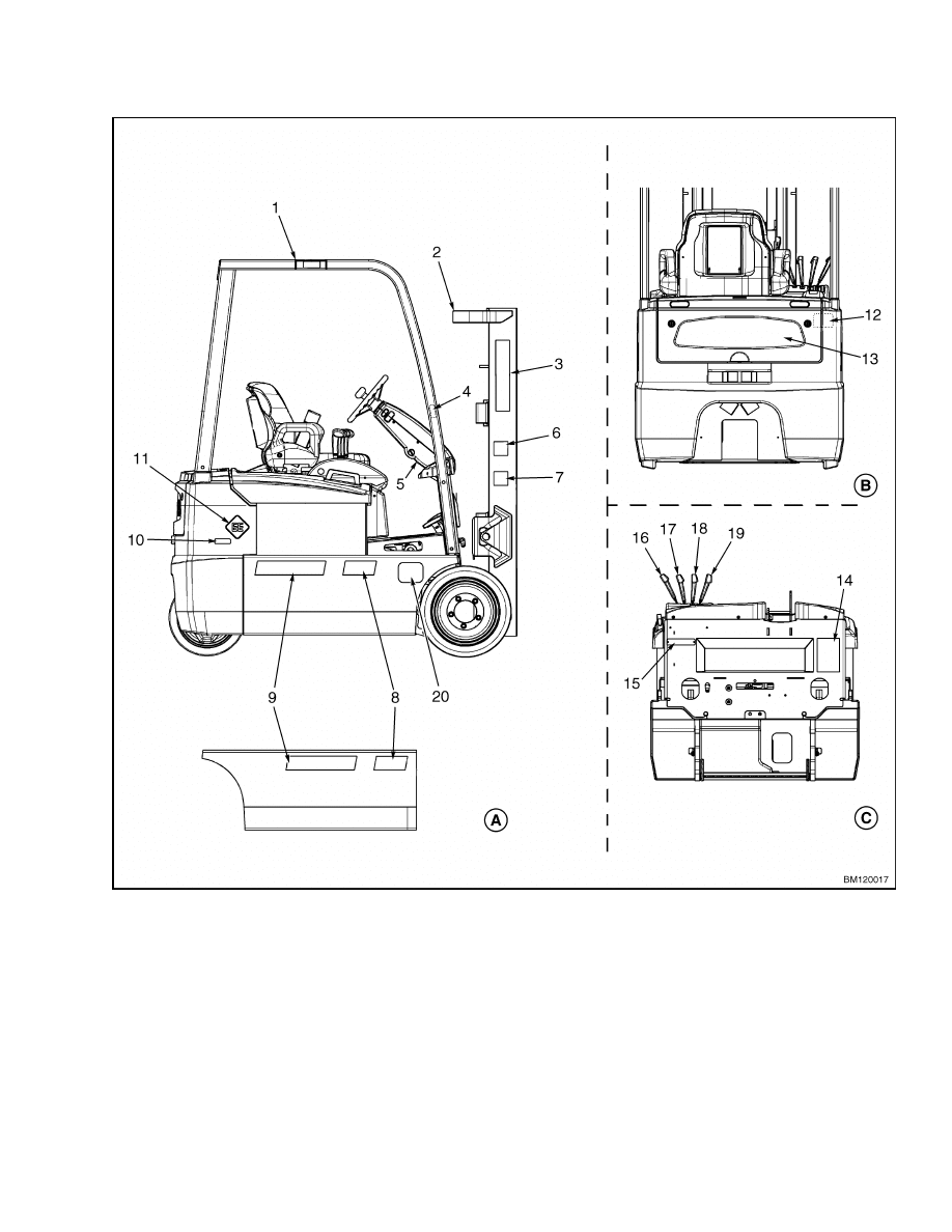
A. SIDE VIEW
B. REAR VIEW
C. FRONT VIEW
1.
OVERHEAD GUARD IMPACT RATING PLATE
2.
MAST WARNING
3.
HYSTER
4.
OPERATOR RESTRAINT
5.
TILT COLUMN
6.
MAST WARNING
7.
PINCH POINT
8.
UNIT NUMBER DECAL
9.
HYSTER
10. CORROSION/FREEZER
11. EE CONSTRUCTION
12. BATTERY SPACER WARNING
13. HYSTER
14. PATENTS AND TRADEMARKS
15. UL LABEL
16. AUXILIARY FUNCTION
17. SIDESHIFT
18. TILT
19. LIFT
20. LABEL (EUROPEAN ONLY)
Figure 11. Label Locations - General
11
Safety Labels
100 SRM 1073
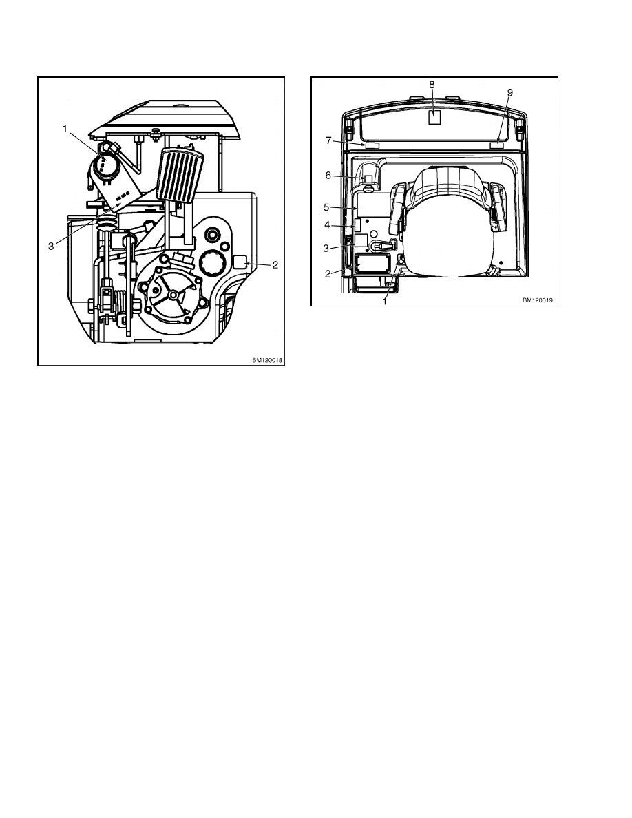
1.
BRAKE SYSTEM FLUID LABEL
2.
HYDRAULIC OIL FILL LABEL
3.
BRAKE SYSTEM FLUID TAG
Figure 12. Label Locations - Below Floor Plates
1.
LOCK/UNLOCK
2.
NAMEPLATE
3.
PINCH POINT
4.
PINCH POINT
5.
OPERATOR WARNING
6.
BATTERY DISCONNECT
7.
PINCH POINT
8.
NO RIDERS
9.
PINCH POINT
Figure 13. Label Locations - Battery
Compartment Cover
12
100 SRM 1073
Painting Instructions
Painting Instructions
WARNING
Always use solvents and paints in an area
with ventilation. Do not use solvents or paints
near heat, fire, or electrical equipment that
can make sparks. Follow the manufacturer’s
instructions and cautions.
1.
Remove all dirt from the surface to be painted.
Clean the area to be painted. Use a solvent for
painted surfaces to remove grease and oil before
sanding. Do not use solvent on new paint. Make
sure all oil and grease is removed.
2.
Use sandpaper to remove the top surface of
paint and rust from the metal. All metal sur-
faces where the paint is completely removed,
must be primed. Apply primer before applying
the paint.
CAUTION
DO NOT put tape on cylinder rods to protect
from paint. Use a thick layer of multipurpose
grease to protect cylinder rods. Cylinders can
be damaged if operated with tape on the cylin-
der rod.
3.
Protect all surfaces that will not be painted.
DO NOT paint:
Pedal Pads
Lever Knobs
Instrument Panel
Steering Wheel
Labels and Information Plates
Seat Assembly and Rails
Information Case
Tires
Mast Chains and Hoses
Battery Connector
Key Switch
Cylinder Rods
All Plastic Covers
CAUTION
Do not paint the pads, plastic covers or knobs,
cables, labels, information plates, or controls.
Paint can make some assemblies not operate
correctly.
4.
Paint the surfaces. Use the correct paint from
your dealer for Hyster lift trucks. Follow the di-
rections on the container.
WARNING
Make sure all labels are installed after paint-
ing is complete. Safety labels are installed on
the lift truck to give information about possi-
ble hazards. It is important that all safety la-
bels are installed on the lift truck and can be
read.
5.
Check that all labels are installed in the correct
locations on the lift truck. See Safety Labels.
NOTE: Use colors approved by Hyster Company.
13

NOTES
____________________________________________________________
____________________________________________________________
____________________________________________________________
____________________________________________________________
____________________________________________________________
____________________________________________________________
____________________________________________________________
____________________________________________________________
____________________________________________________________
____________________________________________________________
____________________________________________________________
____________________________________________________________
____________________________________________________________
____________________________________________________________
____________________________________________________________
____________________________________________________________
____________________________________________________________
____________________________________________________________
____________________________________________________________
____________________________________________________________
14


TECHNICAL PUBLICATIONS
100 SRM 1073
6/04 Printed in United Kingdom
Document Outline
Wyszukiwarka
Podobne podstrony:
897559 0100SRM0545 (06 2004) UK EN
1554635 8000SRM1079 (06 2004) UK EN
1565454 8000SRM1113 (06 2004) UK EN
1554629 1800SRM1076 (03 2004) UK EN
1554632 2000SRM1086 (06 2004) UK EN
1566270 0100SRM1118 (08 2004) UK EN
1554628 1600SRM1075 (03 2004) UK EN
897494 1900SRM0513 (06 2004) UK EN
897390 0100SRM0449 (05 2004) UK EN
1554630 1900SRM1077 (06 2004) UK EN
897880 1400SRM0618 (06 2004) UK EN
897881 1600SRM0619 (06 2004) UK EN
897104 0100SRM0322 (05 2004) UK EN
1554635 8000SRM1079 (06 2004) UK EN
więcej podobnych podstron