FRAME
S6.00-7.00XL (S135-155XL) [B024, C024]
PART NO. 897390
100 SRM 449

SAFETY PRECAUTIONS
MAINTENANCE AND REPAIR
• When lifting parts or assemblies, make sure all slings, chains, or cables are correctly
fastened, and that the load being lifted is balanced. Make sure the crane, cables, and
chains have the capacity to support the weight of the load.
• Do not lift heavy parts by hand, use a lifting mechanism.
• Wear safety glasses.
• DISCONNECT THE BATTERY CONNECTOR before doing any maintenance or repair
on electric lift trucks. Disconnect the battery ground cable on internal combustion lift
trucks.
• Always use correct blocks to prevent the unit from rolling or falling. See HOW TO PUT
THE LIFT TRUCK ON BLOCKS in the Operating Manual or the Periodic Mainte-
nance section.
• Keep the unit clean and the working area clean and orderly.
• Use the correct tools for the job.
• Keep the tools clean and in good condition.
• Always use HYSTER APPROVED parts when making repairs. Replacement parts
must meet or exceed the specifications of the original equipment manufacturer.
• Make sure all nuts, bolts, snap rings, and other fastening devices are removed before
using force to remove parts.
• Always fasten a DO NOT OPERATE tag to the controls of the unit when making repairs,
or if the unit needs repairs.
• Be sure to follow the WARNING and CAUTION notes in the instructions.
• Gasoline, Liquid Petroleum Gas (LPG), Compressed Natural Gas (CNG), and Diesel fuel
are flammable. Be sure to follow the necessary safety precautions when handling these
fuels and when working on these fuel systems.
• Batteries generate flammable gas when they are being charged. Keep fire and sparks
away from the area. Make sure the area is well ventilated.
NOTE:
The following symbols and words indicate safety information in this
manual:
WARNING
Indicates a condition that can cause immediate death or injury!
CAUTION
Indicates a condition that can cause property damage!
Frame
Table of Contents
TABLE OF CONTENTS
General ...............................................................................................................................................................
Description .........................................................................................................................................................
Counterweight Repair .......................................................................................................................................
Remove ...........................................................................................................................................................
Install .............................................................................................................................................................
Hood Repair........................................................................................................................................................
Remove ...........................................................................................................................................................
Install .............................................................................................................................................................
Overhead Guard Repair ....................................................................................................................................
Remove ...........................................................................................................................................................
Install .............................................................................................................................................................
Operator Restraint System Repair ...................................................................................................................
Fuel and Hydraulic Tanks Repair.....................................................................................................................
Inspect ............................................................................................................................................................
Small Leaks, Repair ......................................................................................................................................
Large Leaks, Repair ......................................................................................................................................
Clean ..............................................................................................................................................................
Steam Method of Cleaning........................................................................................................................
Chemical Solution Method of Cleaning....................................................................................................
Additional Preparations for Repair ..............................................................................................................
Radiator Repair..................................................................................................................................................
Remove ...........................................................................................................................................................
Install .............................................................................................................................................................
Exhaust System Repair .....................................................................................................................................
Muffler............................................................................................................................................................
Remove.......................................................................................................................................................
Install .........................................................................................................................................................
Engine Repair ....................................................................................................................................................
Remove ...........................................................................................................................................................
Install .............................................................................................................................................................
Throttle Pedal Adjustment................................................................................................................................
Perkins 1104C-44(RE) Diesel Engine ...........................................................................................................
Safety Labels ......................................................................................................................................................
This section is for the following models:
S6.00-7.00XL (S135-155XL) [B024, C024]
©2004 HYSTER COMPANY
i

"THE
QUALITY
KEEPERS"
HYSTER
APPROVED
PARTS
100 SRM 449
Description
General
This section has the description and repair procedures for the frame and connected parts. Included in this sec-
tion are the frame, counterweight, hood, hydraulic and fuel tanks, radiator, and exhaust system. Also included
are the instructions for removal and installation of the engine.
Description
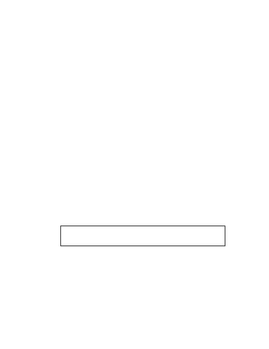
The frame is a one-piece weldment and has mounts for the counterweight, upright, overhead guard, engine
and transmission, axles, and other parts. See Figure 1.
1.
HOOD
2.
FLOOR PLATE
3.
OVERHEAD GUARD
4.
COUNTERWEIGHT
5.
FRAME
Figure 1. Frame and Connected Parts
1
Counterweight Repair
100 SRM 449
Counterweight Repair
REMOVE
WARNING
The lift truck must be put on blocks for some
types of maintenance and repair.
The re-
moval of the following assemblies causes large
changes in the center of gravity:
upright,
drive axle, engine and transmission, and the
counterweight. When the lift truck is put on
blocks, put additional blocks in the following
positions to maintain stability:
a. Before removing the upright and drive axle,
put blocks under the counterweight so that
the lift truck cannot fall backward.
b. Before removing the counterweight, put
blocks under the upright assembly so that
the lift truck cannot fall forward.
The surface must be solid, even, and level when
the lift truck is put on blocks. Make sure that
any blocks used to support the lift truck are
solid, one piece units.
Do not operate the lift truck if the capscrews
for the counterweight are not installed. When
the capscrew is removed, the counterweight
can fall from the lift truck.
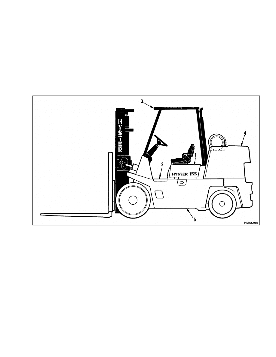
WARNING
Make sure any lifting devices have the correct
capacity for the parts being moved. See Fig-
ure 2.
1.
If the lift truck has an LPG fuel system, remove
the LPG tank and bracket so that the counter-
weight can be removed. See Figure 2.
WARNING
LPG can cause an explosion.
Do not cause
sparks or permit flammable material near the
LPG system. LPG fuel systems can be discon-
nected indoors only if the lift truck is at least
8 m (25 ft) from any open flame, motor vehicles,
electrical equipment, or ignition source.
Close the fuel valve on the LPG tank before any
part of the engine fuel system is disconnected.
Run the engine until the fuel in the system is
used and the engine stops.
If the engine will not run, close the fuel valve
on the LPG tank. Loosen the fitting on the sup-
ply hose from the LPG tank where it enters the
filter unit. Permit the pressure in the fuel sys-
tem to decrease slowly. Fuel leaving the fit-
ting removes heat. Use a cloth to protect your
hands from the cold fitting.
2.
Use the following procedure to remove the LPG
tank:
a. Removable LPG tanks can be removed and
replaced indoors only if the lift truck is at
least 8 m (25 ft) from any open flame or ig-
nition source.
Weight of Counterweights
S6.00XL (S135XL)
2873 to 2953 kg
(6335 to 6511 lb)
S7.00XL (S155XL)
3330 to 3420 kg
(7343 to 7541 lb)
1.
LIFT TRUCK
FRAME
2.
COUNTERWEIGHT
3.
GRILL
4.
CAPSCREW
5.
ACCESS DOOR
6.
TRANSITION
PLATE
7.
HOOD
Figure 2. Counterweight
2

100 SRM 449
Hood Repair
b. Move the lift truck to the area where tanks
are changed.
c.
Turn the tank fuel valve clockwise until the
valve is completely closed.
d. Run the engine until it stops, then turn the
key switch to the OFF position.
e.
Disconnect the quick disconnect fitting.
f.
Release the LPG tank latch and remove the
tank from the bracket.
3.
Open the access door between the counterweight
and the hood. Remove the LPG tank and tank
bracket if the unit has the LPG fuel system.
4.
Install a lifting eye in the hole in the top of the
counterweight. Connect a lifting device to the
lifting eye. Remove the two vertical capscrews
and the capscrew behind the tow pin that hold
the counterweight to the frame.
5.
Lift the counterweight from the frame. Put the
counterweight in a position so that it has stabil-
ity and will not fall.
INSTALL
1.
Connect a lifting device to the lifting eye on the
counterweight. Lift the counterweight into posi-
tion on the frame. See Figure 2.
2.
Install the capscrews for the counterweight.
Tighten the capscrews to 655 N•m (485 lbf ft).
3.
Close the access door. Install the LPG tank on
LPG units.
Hood Repair
REMOVE
1.
Remove the capscrews that fasten the transition
plate. Do NOT remove the plate. See Figure 2.
2.
Open the access door, reach under the transi-
tion plate, and remove the radiator overflow hose
from the two J clamps.
3.
Raise the hood and disconnect the gas assist
cylinder at the hood. Remove the hood, transi-
tion plate, and access door.
INSTALL
1.
Install the hood, transition plate, and access door
in position on the lift truck. Install the capscrews
for the transition plate. Connect the gas assist
cylinder to the hood. Align the hood for the latch
on the front cover. Tighten the capscrews for the
transition plate.
2.
Install the overflow hose in the J clamps. Close
the access door.
WARNING
The hood, hood latch, and latch striker must be
correctly adjusted for the correct operation of
the operator restraint system.
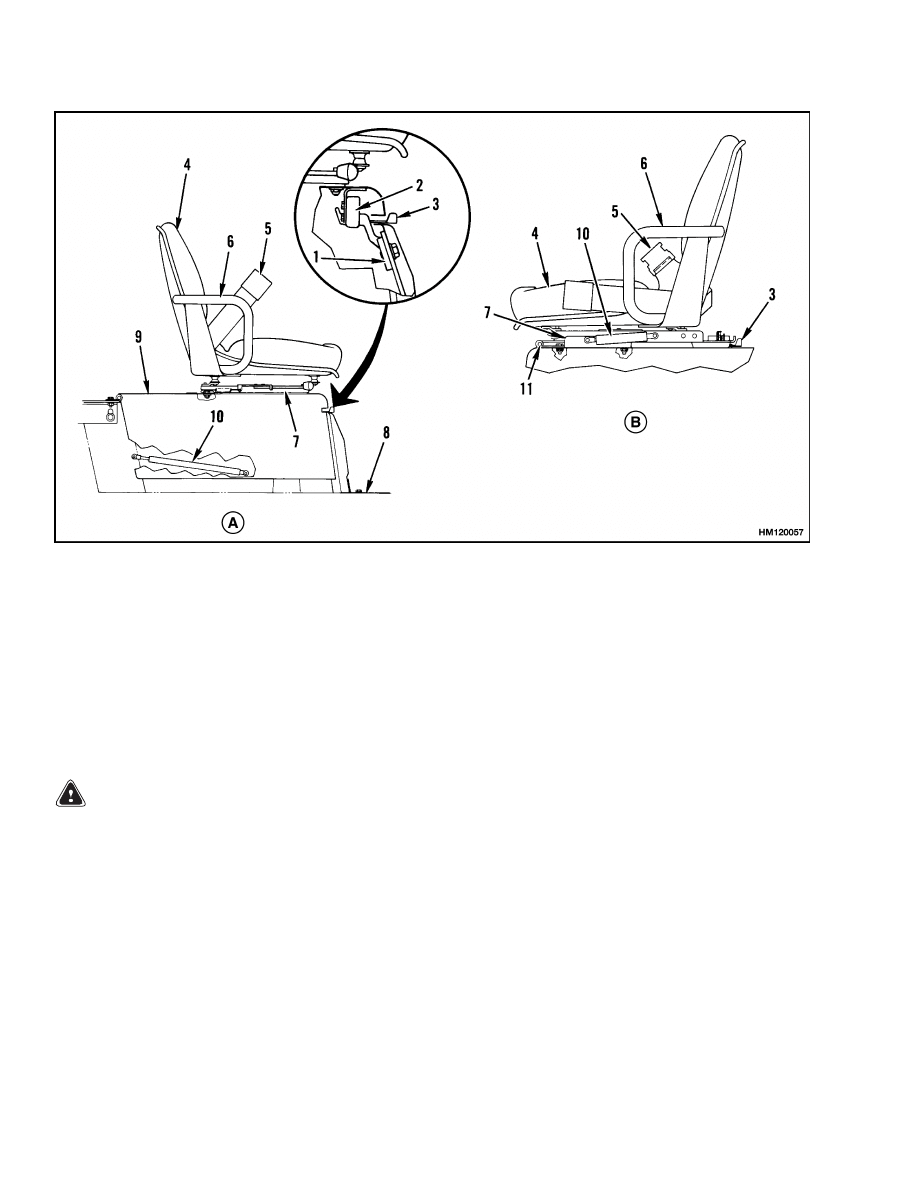
3.
Use the following procedure to adjust the hood
latch (see Figure 3):
a. Install the floor plates and tighten the cap-
screws.
b. Install the latch striker in the highest slot
position on the rear floor plate. Check that
the latch striker is in the center of the jaws
of the hood latch.
c.
Close the hood to the fully-closed position.
The hood latch has two positions. The hood
is fully closed after two clicks of the latch.
d. Loosen the capscrews for the latch striker
just enough to let the striker move. Push
the hood down until the hood just touches the
rubber bumpers on the frame. Make sure the
latch striker is still in the center of the hood
latch. Tighten the capscrews for the latch
striker.
e.
Check the operation of the hood latch. Have
an operator sit in the seat. Make sure the
hood is fully closed (two clicks). Also check
that the hood touches the rubber bumpers.
If necessary, repeat Step d.
3
Overhead Guard Repair
100 SRM 449
A. GAS/DIESEL ARRANGEMENT
B. LPG ARRANGEMENT
1.
LATCH STRIKER
2.
HOOD LATCH
3.
LATCH LEVER
4.
SEAT
5.
SEAT BELT LATCH
6.
HIP RESTRAINT
7.
SEAT RAIL
8.
FLOOR PLATE
9.
HOOD
10. GAS CYLINDER
11. HINGE
Figure 3. Hood and Seat Latches Check
Overhead Guard Repair
REMOVE
WARNING
Do not operate the lift truck without the over-
head guard correctly fastened to the lift truck.
Changes that are made by welding or by
drilling holes that are too big in the wrong
location, can reduce the strength of the over-
head guard. See the instructions for Changes
to the Overhead Guard in the Periodic Mainte-
nance section included with this lift truck.
Connect a lifting device to the top of the overhead
guard. If installed, remove the overhead exhaust
and LPG fuel line clamps. If installed, disconnect
the light wiring harness. Remove the capscrews that
hold the overhead guard to the frame. Remove the
capscrews that hold the overhead guard to the cowl.
Lift the overhead guard from the lift truck.
INSTALL
1.
Connect a lifting device to the top of the overhead
guard. Put the overhead guard in position on the
lift truck.
2.
Install the capscrews at the rear of the overhead
guard. Install the capscrews that hold the over-
head guard to the cowl. Tighten the rear and top
front capscrews to 90 N•m (67 lbf ft). Tighten
the front capscrews under the cowl to 165 N•m
(122 lbf ft).
3.
If removed, install the overhead exhaust and
LPG fuel line. Connect the light wiring harness.
4
100 SRM 449
Fuel and Hydraulic Tanks Repair
Operator Restraint System Repair
The seat belt, hip restraint brackets, seat and mount-
ing, hood, latches, and floor plates are all part of
the operator restraint system. Each item must be
checked to make sure it is attached securely, func-
tions correctly, and is in good condition.
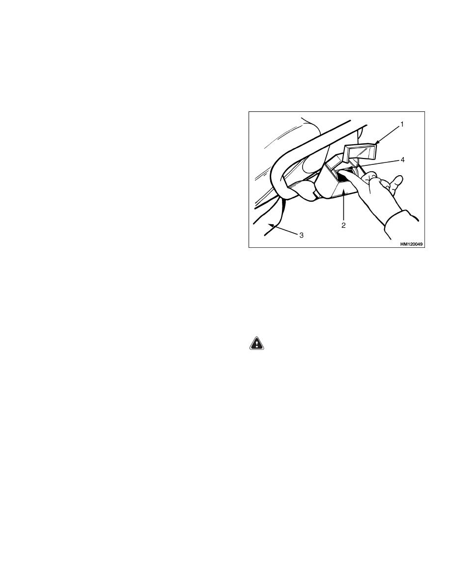
The end of the seat belt must fasten correctly in the
latch. Make sure the seat belt pulls from the re-
tractor assembly and retracts smoothly. The seat
belt must be in good condition. A seat belt that is
damaged or worn will not give protection when it is
needed. If the seat belt cannot be pulled from the
retractor assembly, remove the screw that keeps the
cover on the retractor. Push the bar to release the
spool. Straighten the belt so that it will pull and re-
tract smoothly from the retractor assembly. See Fig-
ure 4.
Make sure the seat rails and latch striker are not
loose. See Figure 3. The seat rails must lock tightly
in position, but move freely when unlocked. The seat
rails must be correctly fastened to the mount surface.
If the mount surface is the hood, the hood must be
fastened to the floor plate with the latch. The floor
plate must be fastened to the lift truck frame. Try to
lift the hood to make sure it is fastened correctly and
will not move.
Adjust the hood, hood latch, and latch striker when
any of the parts of the operator restraint system are
installed or replaced. See the Hood Repair section for
more details.
1.
OPEN COVER
2.
SEAT BELT
RETRACTOR
3.
SEAT BELT
4.
BAR
Figure 4. Release Jammed Seat Belt
Fuel and Hydraulic Tanks Repair
INSPECT
Make a visual inspection of all sides of the tank. In-
spect the welds for cracks and leakage. Check for
wet areas, accumulation of dirt, and loose or miss-
ing paint caused by leakage. Areas of the tank that
are not easily seen can be checked with an inspection
mirror and a light that is approved for locations with
flammable vapors.
SMALL LEAKS, REPAIR
Use the following procedure to repair small leaks:
1.
Use steam to clean the area around the leak. Re-
move all paint and dirt around the leak.
WARNING
Do not use tools that can make sparks, heat, or
static electricity. The vapors in the tank can
cause an explosion.
2.
Apply Loctite
®
290 to the leak. Follow the in-
structions of the manufacturer.
LARGE LEAKS, REPAIR
1.
Use one of the procedures described under Clean
in this section to clean and prepare the tank for
repairs.
2.
Use acceptable welding practices to repair the
tank.
See the American National Standard
Safety In Welding and Cutting AWS Z 49.1 -
1999.
5

Fuel and Hydraulic Tanks Repair
100 SRM 449
CLEAN
WARNING
Special procedures must be followed when
large leaks or other repairs need welding or
cutting. All work must be done by authorized
personnel. If the tank is cleaned inside a build-
ing, make sure there is enough ventilation.
See the following manuals for additional infor-
mation:
• Safe Practices for Welding and Cutting Con-
tainers That Have Held Combustibles, Ameri-
can Welding Society, F4.1 - 1999.
• Safety In Welding and Cutting, American Na-
tional Standard, AWS Z 49.1 - 1999.
When cleaning the tank, do not use solutions that
make dangerous gases at normal temperatures or
when heated. Wear eye and face protection. Protect
the body from burns.
When cleaning with steam, use a hose with a mini-
mum diameter of 19 mm (0.75 in.). Control the pres-
sure of the steam by a valve installed at the nozzle of
the hose. If a metal nozzle is used, it must be made of
a material that does not make sparks. Make an elec-
trical connection between the nozzle and the tank.
Connect a ground wire to the tank to prevent static
electricity.
Steam Method of Cleaning
Use the following procedure to clean the tank with
steam:
1.
Remove all the parts from the tank. Install the
drain plug.
2.
Fill the tank 1/4 full with a solution of water and
sodium bicarbonate or sodium carbonate. Mix
0.5 kg (1 lb) per 4 liter (1 gal) of water.
3.
Mix the solution in the tank using air pressure.
Make sure all the surfaces on the inside of the
tank are flushed with the solution. Drain the
tank.
4.
Put steam into the tank until the tank does not
have odors and the metal is hot. Steam vapors
must come from all the openings.
5.
Flush the inside of the tank with boiling water.
Make sure all the loose material is removed from
the inside of the tank.
6.
Make an inspection of the inside of the tank. If it
is not clean, repeat Step 4 and Step 5 and make
another inspection. When making inspections,
use a light that is approved for locations with
flammable vapors.
7.
Put plugs in all the openings in the tank. Wait 15
minutes, then remove the inlet and outlet plugs.
Test a sample of the vapor with a special indi-
cator for gas vapors. If the amount of flammable
vapors is above the lower flammable limit, repeat
the cleaning procedures.
Chemical Solution Method of Cleaning
If the tank cannot be cleaned with steam, use the
following procedure:
1.
Mix a solution of water and trisodium phosphate
or a cleaning compound with an alkali base. Fol-
low the instructions given by the manufacturer.
2.
Fill the tank with the cleaning solution. Use com-
pressed air to mix the solution in the tank.
3.
Drain the tank. Flush the inside of the tank with
hot (boiling) water. Make sure all the cleaning
compound is removed.
4.
Make an inspection of the inside of the tank.
If the tank is not clean, repeat Step 1 through
Step 3. Make another inspection of the tank.
When making inspections, use a light that is ap-
proved for locations with flammable vapors.
5.
Check the tank for flammable vapors using
special indicator for gas vapors. If the amount
of flammable vapors is not below the lower
flammable limit, repeat the cleaning procedures.
ADDITIONAL PREPARATIONS FOR
REPAIR
If nitrogen gas or carbon dioxide gas is available, pre-
pare the tank for welding using these gases. See the
manual Safe Practices for Welding and Cutting Con-
tainers That Have Held Combustibles by the Ameri-
can Welding Society, F4.1 - 1999. If these gases are
not available, another method using water can be
used as follows:
1.
Fill the tank with water to just below the point
where the work will be done.
Make sure the
space above the level of the water has a vent.
6

100 SRM 449
Exhaust System Repair
2.
Use acceptable welding practices to repair the
tank.
See the American National Standard
Safety In Welding and Cutting AWS Z 49.1 -
1999.
Radiator Repair
REMOVE
NOTE:
To make radiator removal easier, remove
the counterweight as described in Counterweight
Repair, Remove.
1.
Open the access door between the hood and the
counterweight. Remove the cover plate over the
radiator. If installed, remove the LPG tank and
bracket.
2.
Drain the coolant from the radiator. Remove the
radiator hoses. Disconnect the oil lines at the
radiator. Put caps on the open lines.
3.
Remove the remote fill assembly and radiator
hoses to the engine. Disconnect the hose to the
auxiliary coolant reservoir.
4.
Remove the hood and transition plate as de-
scribed in Hood Repair, Remove. Remove the
fan shroud and fan. Loosen the exhaust band
clamp on the gasoline and LPG units. Remove
the engine water outlet on diesel units.
5.
Remove the muffler and inlet exhaust pipe to the
muffler. Remove the capscrews that fasten the
radiator. Move the exhaust pipe for clearance of
the radiator flange.
6.
Tip the radiator forward over the engine as you
lift and remove the radiator.
INSTALL
NOTE:
The installation of the radiator is easier if the
counterweight is removed. See Counterweight Re-
pair, Remove in this section.
1.
Tip the radiator forward over the engine as you
install the radiator in the lift truck. Move the
exhaust pipe for clearance to the radiator flange.
2.
Install the capscrews that fasten the radiator. In-
stall the muffler and inlet exhaust pipe at the
muffler.
3.
Install the engine water outlet on diesel units.
Tighten the exhaust band clamp on gasoline or
LPG units. Install the fan and fan shroud. In-
stall the hood and transition plate as described
in the Hood Repair, Install section.
4.
Connect the hose to the auxiliary coolant reser-
voir. Install the remote fill assembly and radiator
hoses to the engine. Make sure the hose clamp
screws have an access at the wheel wells.
5.
Connect the oil lines at the radiator. Install the
cover plate over the radiator and fill the radiator
with the coolant specified in the table in the Pe-
riodic Maintenance 8000 SRM 393 .
6.
If removed, install the counterweight as de-
scribed in the Counterweight Repair, Install
section. If the LPG tank and bracket were re-
moved, install them.
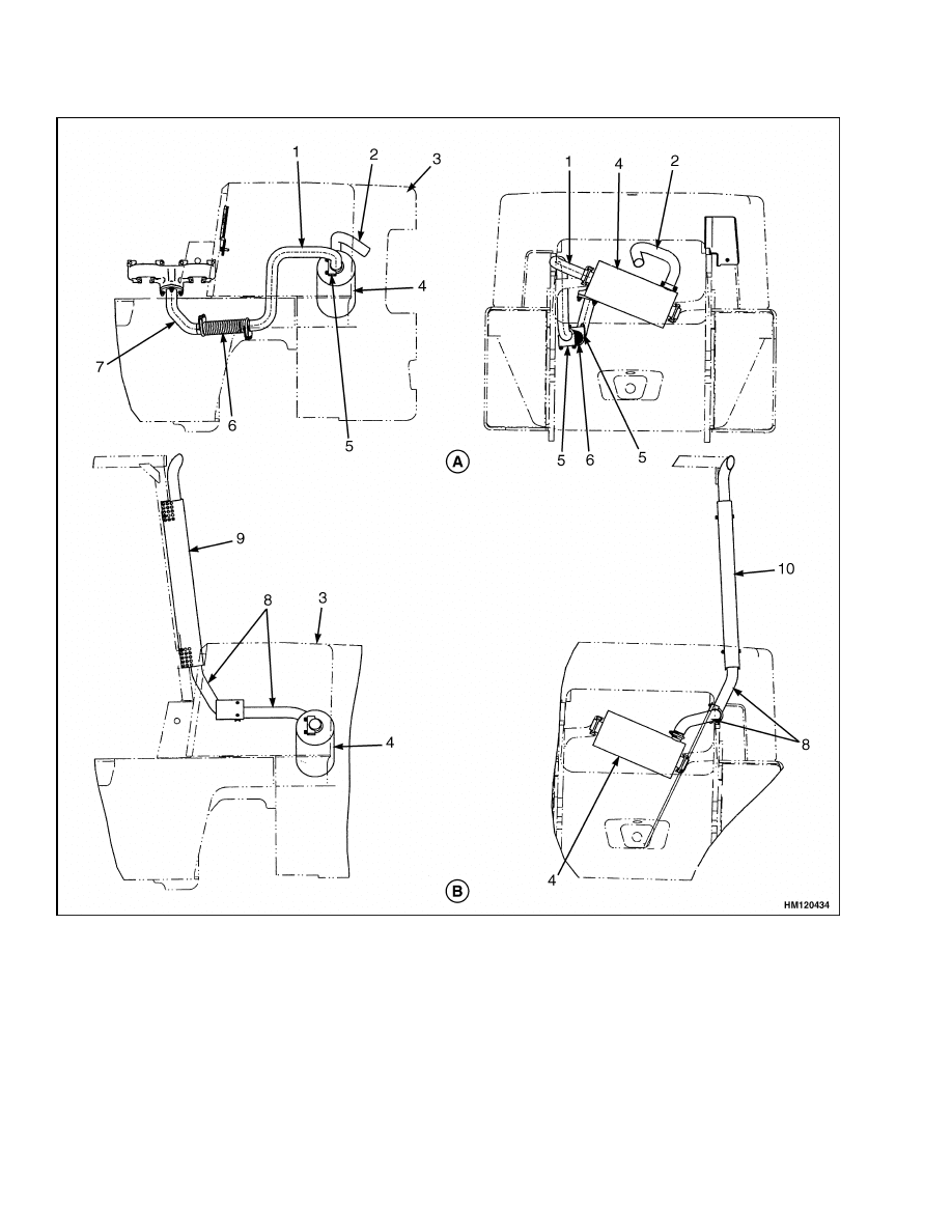
Exhaust System Repair
MUFFLER
Remove
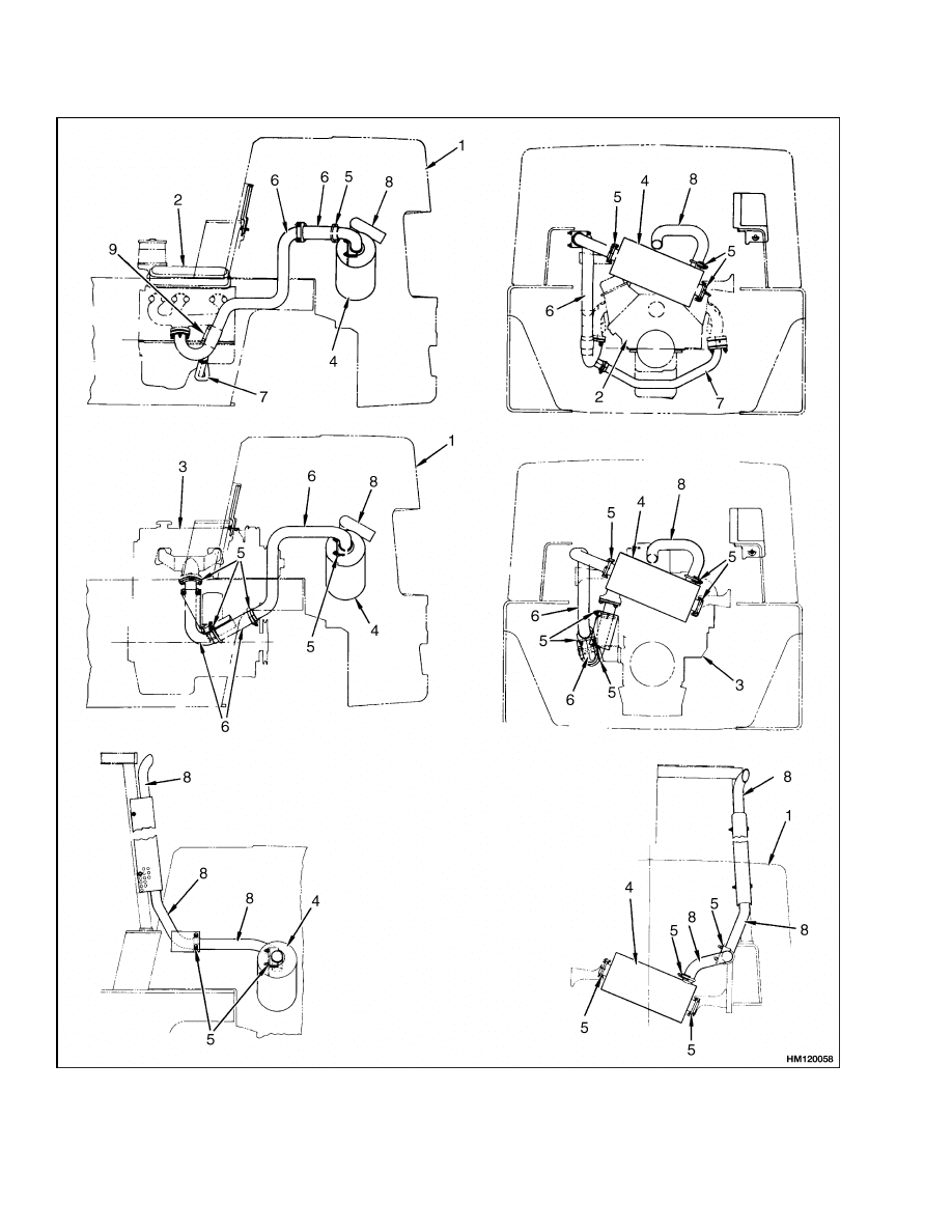
1.
Remove the grill by removing the retaining plate
at the top of the grill. See Figure 5, Figure 6, and
Figure 7.
2.
Disconnect the exhaust pipes and remove the
clamps.
3.
Remove the clamp from the muffler outlet and
remove the muffler.
Install
1.
On overhead exhaust units, install the counter-
weight exhaust pipe on the muffler, but do NOT
tighten. See Figure 5, Figure 6, and Figure 7.
7
Exhaust System Repair
100 SRM 449
Figure 5. Exhaust System
8
100 SRM 449
Exhaust System Repair
Legend for Figure 5
1.
COUNTERWEIGHT
2.
GM-V6 ENGINE
3.
PERKINS ENGINE
4.
MUFFLER
5.
CLAMP
6.
EXHAUST PIPE
7.
CROSSOVER PIPE
8.
TAIL PIPE
9.
BAND CLAMP
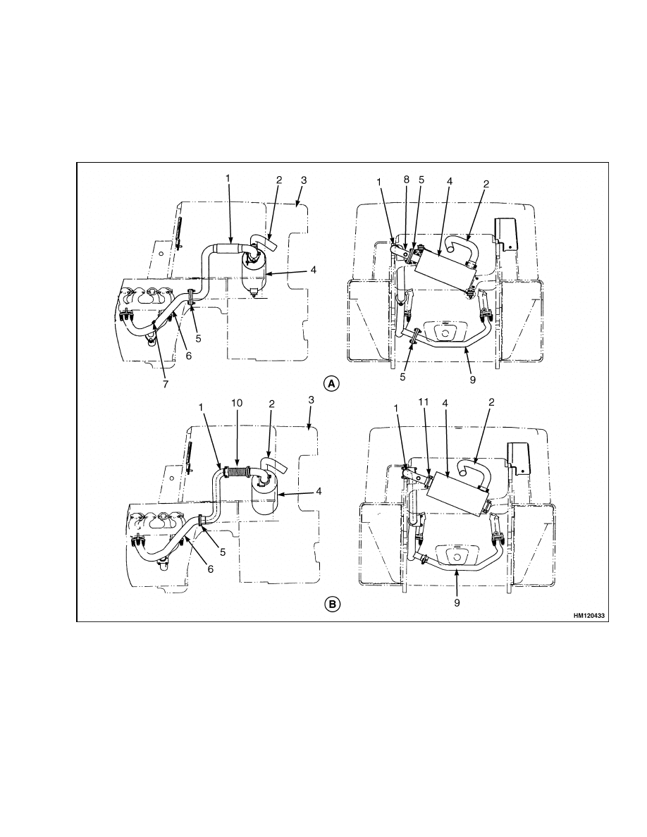
A. GAS/LPG COUNTERWEIGHT EXHAUST EPA COMPLIANT
B. GAS/LPG COUNTERWEIGHT EXHAUST NON-EPA COMPLIANT
1.
UPPER EXHAUST PIPE
2.
TAIL PIPE
3.
COUNTERWEIGHT
4.
MUFFLER
5.
GASKET
6.
LOWER EXHAUST PIPE
7.
RAW GAS CHECK PORT
8.
OXYGEN SENSOR PORT
9.
CROSSOVER PIPE
10. FLEX PIPE
11. CLAMP
Figure 6. Exhaust System EPA Compliant Engine
9
Exhaust System Repair
100 SRM 449
A. DIESEL COUNTERWEIGHT EXHAUST EPA COMPLIANT
B. GAS/LPG/DIESEL OVERHEAD EXHAUST
1.
UPPER EXHAUST PIPE
2.
TAIL PIPE
3.
COUNTERWEIGHT
4.
MUFFLER
5.
CLAMP
6.
FLEX PIPE
7.
LOWER EXHAUST PIPE
8.
OVERHEAD TAIL PIPE
9.
OUTER SHIELD
10. INNER SHIELD
Figure 7. Exhaust System, Diesel EPA Compliant
10

100 SRM 449
Engine Repair
2.
Install the muffler and, on units with the over-
head exhaust, rotate the muffler so the outlet is
at the top. Install the other exhaust pipes and
tighten the clamps. Rotate the counterweight
exhaust pipe so that it points straight back and
down at a 45 angle.
3.
Install the grill and align the end of the counter-
weight exhaust pipe so that it is between the grill
bars.
Engine Repair
REMOVE
NOTE:
The lift truck can have a powershift or a man-
ual transmission. The powershift transmission and
the torque converter are attached to the engine. The
engine and powershift transmission are normally re-
moved as a unit. The manual transmission is at-
tached to the drive axle housing. This engine is re-
moved without removing the manual transmission.
1.
Put the lift truck on blocks. See the Operating
Manual or the section Periodic Maintenance
8000 SRM 393 for the correct procedures to put
the lift truck on blocks. Remove the overhead
guard, hood, transition plate, and access door.
See the Hood Repair, Remove section for more
details. Remove the floor plates.
2.
Disconnect the cables at the battery. Remove the
battery, air cleaner inlet duct, and battery tray.
Disconnect the brake fluid reservoir and engine
crankcase breather lines.
3.
Remove the fan and fan shroud. Disconnect the
exhaust pipe at the exhaust headers.
4.
Disconnect the fuel lines at the engine. Discon-
nect the throttle linkage at the engine. Discon-
nect the wires and wiring harnesses at the engine
and powershift transmission.
5.
Disconnect the oil lines at the hydraulic pumps.
Drain the hydraulic tank and put plugs in the
open ports. Disconnect the oil cooler lines from
the powershift transmission.
6.
Powershift transmission.
Do the following
procedure:
a. Disconnect the linkage between the trans-
mission and the pedals at the transmission.
b. Disconnect the hydraulic lines to the brake
booster.
c.
Disconnect the brake line at the booster. Dis-
connect the electrical wiring.
d. Remove the pedal bracket.
e.
On units without the MONOTROL
®
pedal,
disconnect the direction control linkage at
the transmission.
f.
Disconnect the drive line at the universal
joint.
7.
Manual transmission. Do the following proce-
dure:
a. Disconnect the drive line at the universal
joint near the clutch.
b. Disconnect the hydraulic and brake lines.
Disconnect the push rod to the brake booster.
Disconnect the electrical wiring.
WARNING
Do NOT leave the clutch pedal free in the up
position with the over-center spring installed.
The spring is under tension and can cause an
injury. Fasten the clutch pedal so that it can-
not move down, remove the spring or carefully
move the pedal to the down position to remove
the tension.
c.
Remove the brake booster. Disconnect the
clutch push rod from the clutch cover.
8.
Connect a lifting device to the engine. Make sure
the lifting device has a capacity of at least 450 kg
(1000 lb). Remove the four motor mount bolts.
Raise the engine from the frame. Be careful of
the hydraulic pump. Make sure that all wires
and hoses are disconnected. Put the engine in a
position so that it has stability and will not fall.
9.
Remove the powershift transmission from the
engine as described in the Two-Speed Power-
shift Transmission, Troubleshooting and
Repairs 1300 SRM 325 .
On units with the
manual transmission, remove the oil clutch
housing and clutch cover from the engine.
11
Engine Repair
100 SRM 449
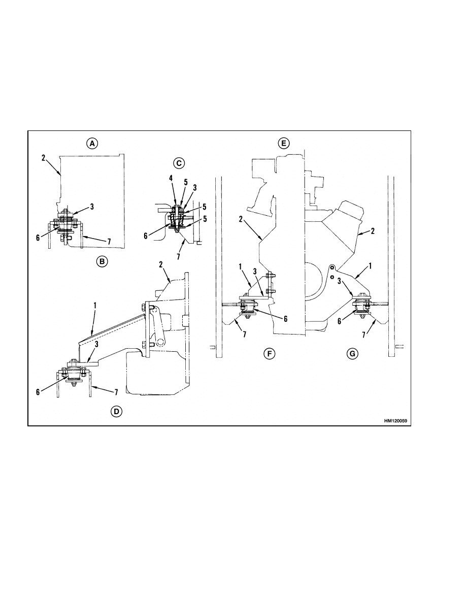
INSTALL
1.
Install the engine mounts on the engine as fol-
lows (see Figure 8):
a. GM V-6: Tighten the capscrews that hold the
engine mount to the fan end of the engine to
30 N•m (22 lbf ft). Tighten the bolts that
hold the engine mounts to the mount plate
to 65 N•m (48 lbf ft).
b. PERKINS: Apply a sealant to the threads of
the capscrews and tighten the capscrews that
hold the engine mounts to the fan end of the
engine to 65 N•m (48 lbf ft).
A. FRONT MOUNTS
B. PERKINS, POWERSHIFT
C. GM-V6, POWERSHIFT ONLY
D. PERKINS, GM-V6 MANUAL ONLY
E. REAR MOUNTS
F.
PERKINS
G. GM-V6
1.
ENGINE OR TRANSMISSION MOUNT
2.
ENGINE, TRANSMISSION, OR CLUTCH
HOUSING
3.
MOUNT PLATE
4.
BOLT
5.
WASHER
6.
RUBBER MOUNT
7.
FRAME MOUNT WELDMENT
Figure 8. Engine Mounts
12

100 SRM 449
Engine Repair
CAUTION
Apply a sealant (Hyster Part Number 264159) to
the flange of the flywheel housing. Make sure
the torque converter or clutch is installed cor-
rectly and engaged with the oil pump. If the
parts are not engaged, the oil pump or torque
converter will be damaged.
2.
If removed, install the torque converter and pow-
ershift transmission on the engine as described
in the Two-Speed Powershift Transmission,
Troubleshooting and Repairs 1300 SRM 325
. If removed, install the oil clutch housing and
cover on the engine.
3.
Connect a lifting device to the engine. Make sure
the lifting device has a capacity of at least 450 kg
(1000 lb). Install the engine in the unit. Be care-
ful of the hydraulic pump. Make sure that all
wires and hoses are not damaged. Install the
four motor mount bolts. Connect all hoses and
wiring. Make sure the clamp screws for the radi-
ator hoses are aligned for access from the wheel
wells.
4.
Install the bolts for the engine mounts. See Fig-
ure 5. Tighten the bolts to 120 N•m (89 lbf ft).
5.
Powershift transmission:
do the following
procedure:
a. Connect the drive line at the universal joint.
b. On units without the MONOTROL pedal,
connect the direction control linkage at the
transmission.
c.
Install the pedal bracket. Connect the brake
line at the booster.
d. Connect the hydraulic lines to the brake
booster.
e.
Connect the linkage between the transmis-
sion and the pedals at the transmission.
f.
Connect the oil cooler lines for the transmis-
sion.
6.
Manual transmission: do the following proce-
dure:
a. Install the brake booster. Connect the clutch
push rod to the clutch cover.
b. Connect the hydraulic and brake lines. Con-
nect the push rod to the brake booster.
c.
Connect the drive line at the universal joint
near the clutch.
7.
Connect the oil lines at the hydraulic pumps. Fill
the hydraulic tank with the oil specified in the
Periodic Maintenance 8000 SRM 393 .
8.
Connect the fuel lines at the engine. Connect the
throttle linkage at the engine.
9.
Connect the exhaust pipe at the exhaust header.
Install the fan and fan shroud.
10. Connect the engine crankcase breather and the
brake fluid reservoir lines. Install the battery
tray, air cleaner inlet duct, and battery. Connect
the cables at the battery.
11. Install the floor plates.
Install the overhead
guard and the hood, transition plate, and access
door. See the Hood Repair, Install in this section.
Remove the blocks that support the lift truck
using the reverse of the installation procedure
in the Periodic Maintenance 8000 SRM 393
or in the Operating Manual.
12. Check all of the fluid levels and fill as necessary.
Remove the air from the brake system.
13
Throttle Pedal Adjustment
100 SRM 449
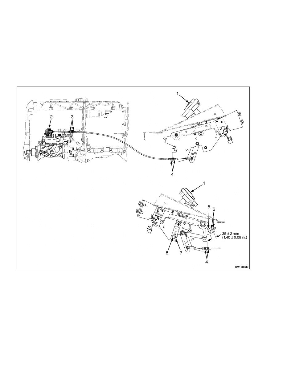
Throttle Pedal Adjustment
PERKINS 1104C-44(RE) DIESEL ENGINE
NOTE: The procedures below are for lift trucks
equipped with the Perkins 1104C-44(RE) Diesel
Engine. If your lift truck has either a gas or LPG
engine, see the section LPG Fuel System 900 SRM
348 for the procedures to adjust the throttle linkage.
1.
Adjust the cable adjustment nuts to allow for a
3.0 mm (0.12 in.) maximum of free play on the
throttle cable length. See Figure 9. Secure cable
length by tightening cable locknuts.
2.
Set pedal stop to 35 ±2 mm (1.40 ±0.08 in.). Se-
cure in place with pedal stop jam nuts.
NOTE: THE MONOTROL PEDAL IS SHOWN. THE ADJUSTMENT PROCEDURES FOR THE ACCELERATOR
PEDAL ARE THE SAME.
1.
MONOTROL PEDAL
2.
DIESEL INJECTOR PUMP
3.
CABLE ADJUSTMENT NUTS
4.
CABLE LOCKNUTS
5.
PEDAL STOP JAM NUTS
6.
PEDAL STOP
7.
UP POSITION PEDAL STOP
8.
CAPSCREW
Figure 9. MONOTROL And Accelerator Pedal Adjustment
14
100 SRM 449
Safety Labels
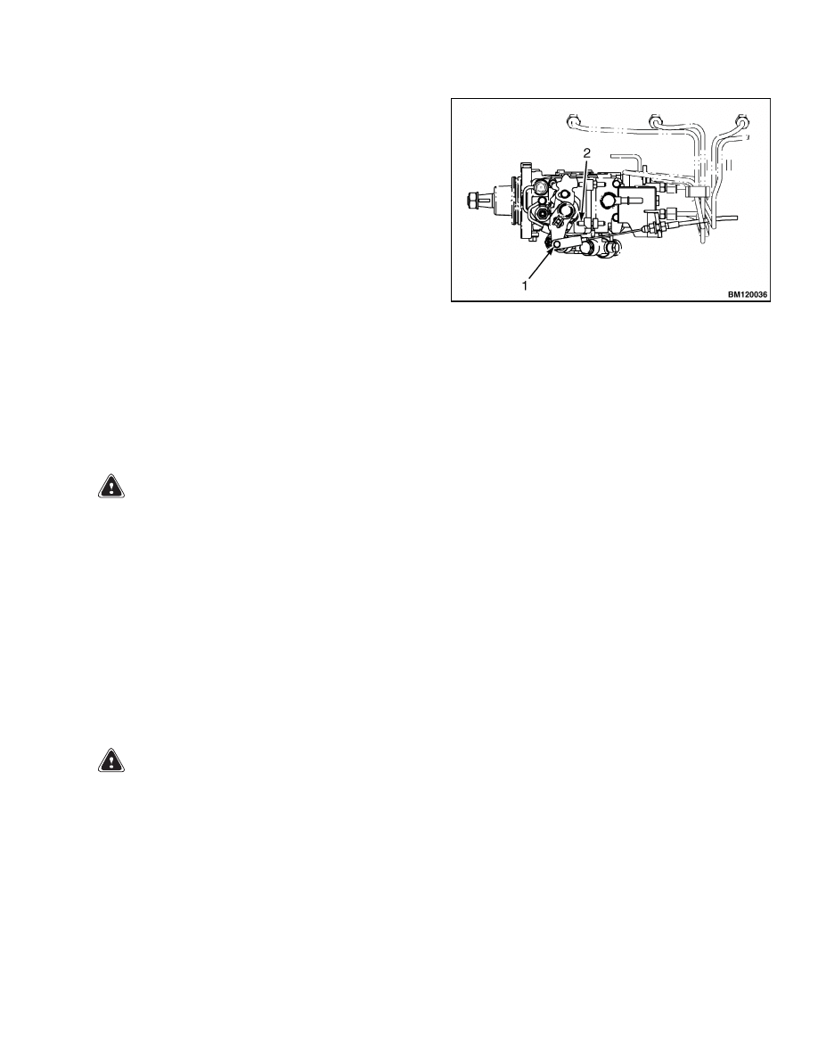
3.
With the pedal against the stop, adjust the throt-
tle cable to ensure that the diesel injector pump
is at full power (the injection pump lever is touch-
ing the lever stop in Figure 10).
4.
Release the throttle pedal and adjust the up posi-
tion pedal stop until the tension is removed from
the cable when the injection pump lever is re-
turned to the idle position. Tighten up position
pedal stop with capscrew. See Figure 9.
NOTE: DIESEL INJECTOR PUMP IS SHOWN IN THE
IDLE POSITION.
1.
INJECTION PUMP LEVER
2.
LEVER STOP
Figure 10. Diesel Injector Pump
Safety Labels
WARNING
Safety labels are installed on the lift truck to
give information about operation and possible
hazards. It is important that all safety labels
are installed on the lift truck and can be read.
DO NOT add to or modify the lift truck. Any
change to the lift truck, the tires, or its equip-
ment can change the lifting capacity. The lift
truck must be rated as equipped and the name-
plate must show the new capacity rating. Con-
tact your dealer for Hyster lift trucks for a re-
placement nameplate.
If a label must be replaced, use the following proce-
dure to install a new label (see Figure 11):
WARNING
Cleaning solvents can be flammable and toxic
and can cause skin irritation.
When using
cleaning solvents, always follow the recom-
mendations of the manufacturer.
1.
Make sure the surface is dry and has no oil or
grease. Do not use solvent on new paint. Clean
the surface of old paint with a cleaning solvent.
2.
Remove the paper from the back of the label. Do
not touch the adhesive surface.
3.
Carefully hold the label in the correct position
above the surface. The label cannot be moved
after it touches the surface. Put the label on the
surface. Make sure that all air is removed from
under the label and the corners and edges are
tight.
15
Safety Labels
100 SRM 449
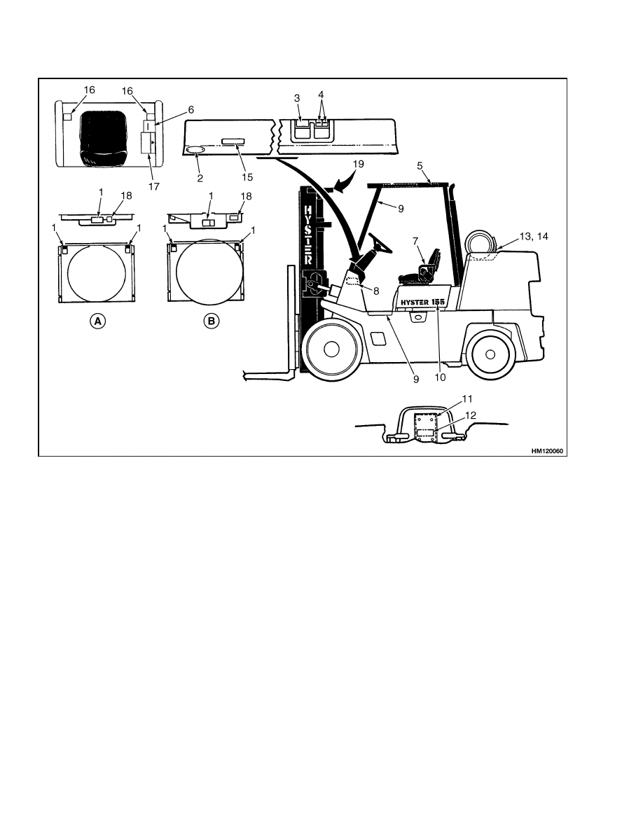
A. GASOLINE/LPG
B. DIESEL
1.
FAN WARNING (ON SHROUD)
2.
INSPECTION PLATE, UL
3.
HOIST/TILT
4.
AUXILIARY FUNCTIONS
5.
IMPACT RATING PLATE
6.
NAMEPLATE (INFORMATION MUST BE
COMPLETE)
7.
OPERATOR RESTRAINT (FOR EQUIPPED
UNITS) OR TIPOVER WARNING (FOR OTHER
UNITS)
8.
PATENT LABEL (INSIDE COWL, RIGHT)
9.
SAFETY TREAD (LEFT AND RIGHT)
10. MODEL LABEL (2)
11. CASE, OPERATING MANUAL
12. REPLACE OPERATING MANUAL LABEL
(NOT REQUIRED FOR ENGLISH SPEAKING
COUNTRIES)
13. FLAMMABLE LP GAS
14. LABEL, LP TANK IDENTIFIER (U.S. AND
CANADA ONLY)
15. PARKING BRAKE WARNING
16. NO RIDERS
17. OPERATOR WARNING
18. ANTIFREEZE
19. MAST WARNING
Figure 11. Label Positions
16


TECHNICAL PUBLICATIONS
100 SRM 449
5/04 (12/03)(4/97)(3/89) Printed in United Kingdom
Document Outline
- toc
Wyszukiwarka
Podobne podstrony:
897104 0100SRM0322 (05 2004) UK EN
897506 4000SRM0521 (05 2004) UK EN
897067 1400SRM0285 (05 2004) UK EN
910460 1600SRM0258 (05 2004) UK EN
1566270 0100SRM1118 (08 2004) UK EN
1467764 8000SRM0738 (05 2004) UK EN
1554626 0100SRM1073 (06 2004) UK EN
897559 0100SRM0545 (06 2004) UK EN
1553986 8000SRM1083 (05 2004) UK EN
897455 0100SRM0486 (05 1992) UK EN
897506 4000SRM0521 (05 2004) UK EN
więcej podobnych podstron