BRAKE SYSTEM
J1.6-2.0XMT (J30-40ZT) [J160]
PART NO. 1554629
1800 SRM 1076

SAFETY PRECAUTIONS
MAINTENANCE AND REPAIR
• When lifting parts or assemblies, make sure all slings, chains, or cables are correctly
fastened, and that the load being lifted is balanced. Make sure the crane, cables, and
chains have the capacity to support the weight of the load.
• Do not lift heavy parts by hand, use a lifting mechanism.
• Wear safety glasses.
• DISCONNECT THE BATTERY CONNECTOR before doing any maintenance or repair
on electric lift trucks.
• Disconnect the battery ground cable on internal combustion lift trucks.
• Always use correct blocks to prevent the unit from rolling or falling. See HOW TO PUT
THE LIFT TRUCK ON BLOCKS in the Operating Manual or the Periodic Mainte-
nance section.
• Keep the unit clean and the working area clean and orderly.
• Use the correct tools for the job.
• Keep the tools clean and in good condition.
• Always use HYSTER APPROVED parts when making repairs. Replacement parts
must meet or exceed the specifications of the original equipment manufacturer.
• Make sure all nuts, bolts, snap rings, and other fastening devices are removed before
using force to remove parts.
• Always fasten a DO NOT OPERATE tag to the controls of the unit when making repairs,
or if the unit needs repairs.
• Be sure to follow the WARNING and CAUTION notes in the instructions.
• Gasoline, Liquid Petroleum Gas (LPG), Compressed Natural Gas (CNG), and Diesel fuel
are flammable. Be sure to follow the necessary safety precautions when handling these
fuels and when working on these fuel systems.
• Batteries generate flammable gas when they are being charged. Keep fire and sparks
away from the area. Make sure the area is well ventilated.
NOTE:
The following symbols and words indicate safety information in this
manual:
WARNING
Indicates a condition that can cause immediate death or injury!
CAUTION
Indicates a condition that can cause property damage!

Brake System
Table of Contents
TABLE OF CONTENTS
Introduction........................................................................................................................................................
General ...........................................................................................................................................................
Discharging the Capacitors...........................................................................................................................
Brake Pedal Assembly .......................................................................................................................................
Remove ...........................................................................................................................................................
Disassemble ...................................................................................................................................................
Assemble ........................................................................................................................................................
Install .............................................................................................................................................................
Master Cylinder .................................................................................................................................................
Remove ...........................................................................................................................................................
Install .............................................................................................................................................................
Adjustments ...................................................................................................................................................
Bleed the Brake System............................................................................................................................
Adjust Linkage ..........................................................................................................................................
Brake Lines ........................................................................................................................................................
Parking Brake ....................................................................................................................................................
Remove ...........................................................................................................................................................
Disassemble ...................................................................................................................................................
Assemble ........................................................................................................................................................
Install .............................................................................................................................................................
Troubleshooting..................................................................................................................................................
This section is for the following models:
J1.6-2.0XMT (J30-40ZT) [J160]
©2004 HYSTER COMPANY
i

"THE
QUALITY
KEEPERS"
HYSTER
APPROVED
PARTS
1800 SRM 1076
Introduction
Introduction
GENERAL
This section contains the description and repair
procedures for the brake system.
Components
covered are the brake pedal assembly, the spring-ap-
plied/electrically-released parking brakes, and the
master cylinder system. Some parts associated with
the brake system are not covered in this section
because they are more closely associated with other
systems. See the following list for information not
included in this section:
See the section Electrical System 2200 SRM
1078 for information on brake lights and parking
brake wiring.
See the section Transaxle 630 SRM 1074 for in-
formation on the internal, wet brake system.
Throughout this section, forward will refer to travel
in the direction of the forks and left and right deter-
mined by an operator sitting in the seat facing for-
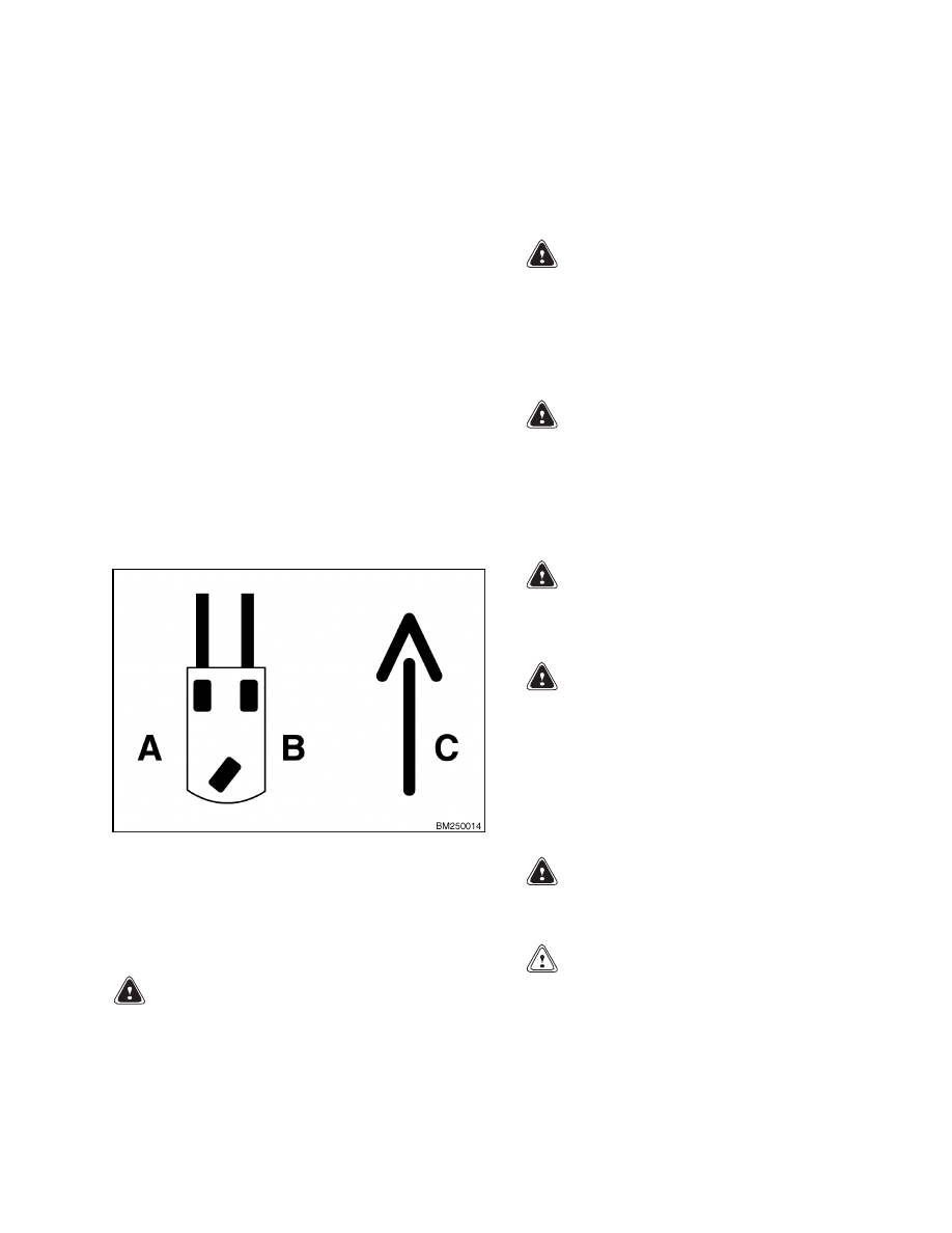
ward. See Figure 1.
A. LEFT SIDE
B. RIGHT SIDE
C. FORWARD TRAVEL
Figure 1. Truck Orientation
DISCHARGING THE CAPACITORS
WARNING
Do not make repairs or adjustments unless you
have both authorization and training. Repairs
and adjustments that are not correct can cre-
ate dangerous operating conditions. Do not op-
erate a lift truck that needs repairs. Report
the need for repairs to your supervisor imme-
diately. If repair is necessary, attach a DO NOT
OPERATE tag on the steering wheel. Remove
the key from the key switch.
WARNING
Disconnect the battery before opening the
drive unit compartment cover or inspecting or
repairing the electrical system. If a tool causes
a short circuit, the high current flow from the
battery can cause personal injury or property
damage.
WARNING
Some checks and adjustments are done with
the battery connected.
Do not connect the
battery until the procedure tells you to do so.
Never have any metal on your fingers, arms,
or neck. Metal items can accidentally make an
electrical connection and cause injury.
WARNING
Before performing any tests or adjustments,
block the lift truck to prevent unexpected
movement.
WARNING
The capacitor in the transistor controller(s)
can hold an electrical charge after the battery
is disconnected. To prevent an electrical shock
and personal injury, discharge the capacitor(s)
before inspecting or repairing any component
in the drive unit compartment.
Wear safety
glasses.
Make certain that the battery has
been disconnected.
WARNING
DO NOT short across the motor controller ter-
minals with a screwdriver or jumper wire.
CAUTION
To avoid controller damage, always disconnect
the battery, discharge the capacitor(s), and
never put power to the controller while any
power wires are disconnected.
Never short
any controller terminal or motor terminal to
1
Introduction
1800 SRM 1076
the battery. Make sure to use proper proce-
dure when servicing the controller.
1.
Turn key switch to OFF position and disconnect
the battery.
Block load wheels to prevent lift
truck from moving.
2.
Remove two screws securing the electrical com-
partment and pull the compartment door open on
its hinges.
NOTE:
Some lift trucks are equipped with a premium
controller, which controls the hydraulic motor as well
as the traction motors.
3.
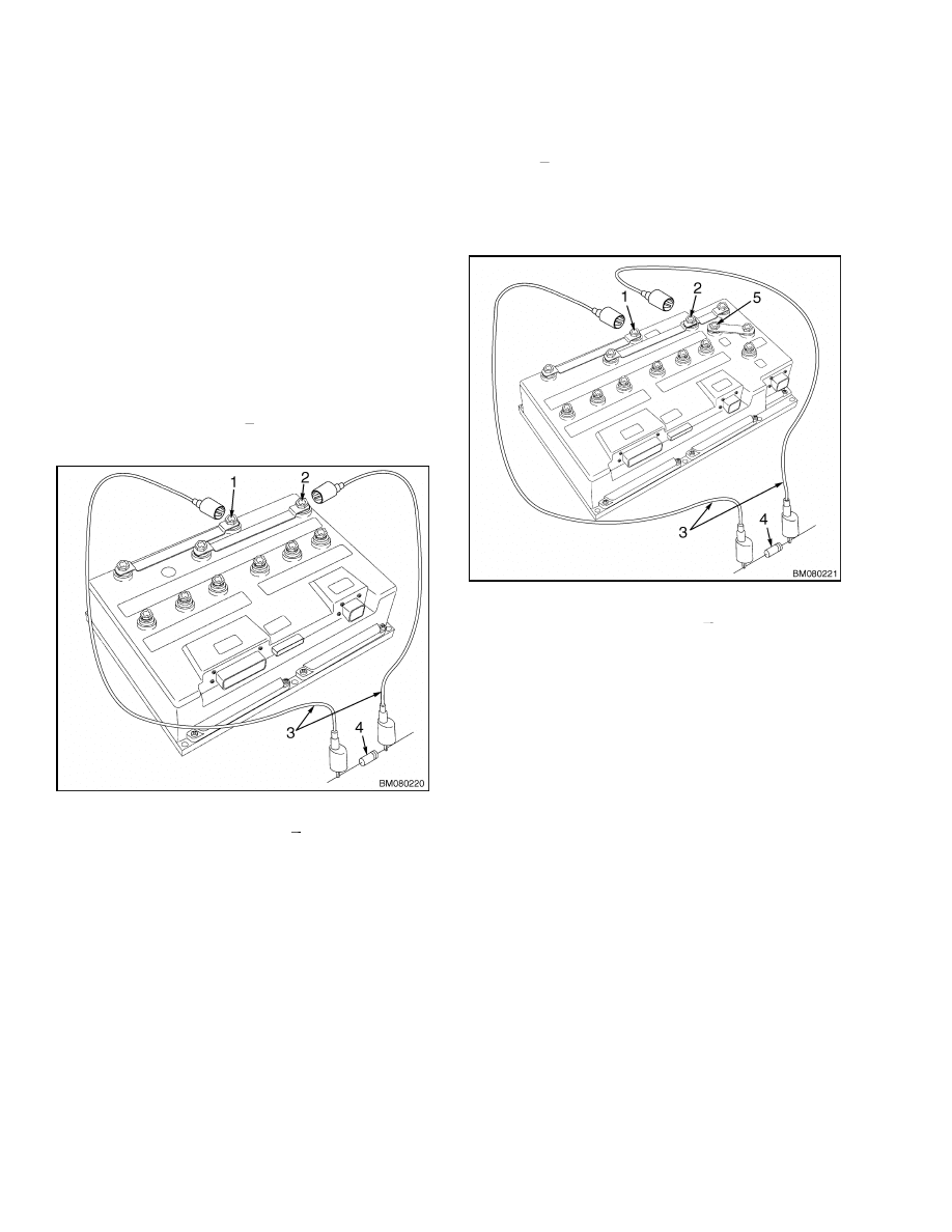
Discharge the capacitor in the controller by con-
necting a 200-ohm, 2-watt resistor across the
controller’s BT+ and B
terminals for 10 seconds
using insulated jumper wires. See Figure 2.
1.
POSITIVE CONNECTION (BT+)
2.
NEGATIVE CONNECTION (B )
3.
INSULATED JUMPER WIRES
4.
200-OHM, 2-WATT RESISTOR
Figure 2. Discharging the Capacitors
(Standard)
4.
On the premium controller, also connect the 200-
ohm, 2-watt resistor across the controller’s P+
and B
terminals for 10 seconds using insulated
jumper wires. See Figure 3.
5.
Remove the 200-ohm, 2-watt resistor before re-
connecting the battery.
1.
POSITIVE CONNECTION (BT+)
2.
NEGATIVE CONNECTION (B )
3.
INSULATED JUMPER WIRES
4.
200-OHM, 2-WATT RESISTOR
5.
POSITIVE CONNECTION (P+)
Figure 3. Discharging the Capacitors
(Optional)
2
1800 SRM 1076
Brake Pedal Assembly
Brake Pedal Assembly
REMOVE
It is not always necessary to remove the brake pedal
assembly to disassemble certain components. Parts
of the brake pedal assembly may be removed without
removing the assembly from the lift truck. The en-
tire removal procedure is outlined below. Evaluate
the required service to determine if the entire brake
assembly should be removed. Perform only the steps
necessary to complete the required service. For the
following procedures, refer to Figure 4.
1.
Turn the key switch to the OFF position and dis-
connect the battery.
2.
Remove floor mat and floor covers.
3.
Tag and disconnect brake switch wires and the
brake fluid sensor wiring harness.
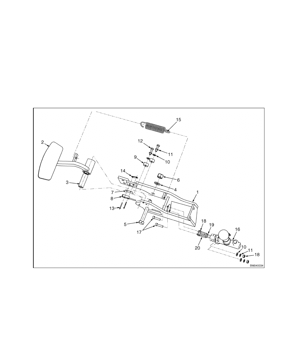
1.
BRACKET
2.
PEDAL
3.
BUSHING
4.
WASHER
5.
BOLT
6.
NUT
7.
INSULATOR
8.
BRAKE SWITCH
9.
PEDAL STOP
10. WASHER
11. LOCKWASHER
12. CAPSCREW
13. SCREW
14. NUTPLATE
15. SPRING
16. MASTER CYLINDER
17. SOCKET-HEAD CAPSCREWS
18. CLEVIS PIN
19. JAM NUT
20. CLEVIS
Figure 4. Brake Pedal Assembly
3

Master Cylinder
1800 SRM 1076
4.
Disconnect the brake supply line from the elbow
fitting on top of the master cylinder.
5.
Remove four capscrews and lockwashers secur-
ing bracket to frame.
6.
Lift brake pedal assembly from the lift truck.
DISASSEMBLE
For the following procedures, refer to Figure 4.
1.
Remove brake switch and insulator from bracket
by removing two screws (13) and nutplate if nec-
essary.
2.
Remove capscrews (12), lockwashers (11), and
washers (10) securing stops to bracket if neces-
sary.
3.
Remove master cylinder if necessary. See Mas-
ter Cylinder, Remove in this section.
4.
Remove brake pedal:
a. Remove pedal return spring.
b. Pull the cotter pin and remove clevis pin from
master cylinder if not already removed.
c.
Remove nut (6) and washer (4), and then
slide bolt (5) from assembly.
d. Lift pedal from assembly.
e.
Remove bushing from pedal if necessary.
ASSEMBLE
1.
Install master cylinder if removed. See Master
Cylinder, Remove in this section.
2.
Install brake pedal:
a. Install new bushing into pedal if removed.
b. Position pedal into bracket and align holes.
c.
Install bolt through bracket and pedal and
secure with bolt (5), washer (4), and nut (6).
d. Install master cylinder linkage to pedal us-
ing clevis pin and secure using cotter pin.
e.
Install pedal return spring.
CAUTION
Do not overtighten switch. Overtightening can
damage plastic casing.
3.
Install brake switch and insulator to bracket us-
ing two screws (13) and nutplate. Adjust switch
as necessary.
4.
Install stops to bracket using capscrews (12),
lockwashers (11), and washers (10).
INSTALL
1.
Place brake pedal assembly in position and align
the mounting holes.
2.
Install four capscrews and lockwashers securing
bracket to frame.
3.
Connect brake switch wires and the brake fluid
sensor wiring harness as removed.
4.
Connect the brake supply line to the elbow fitting
on top of the master cylinder.
5.
Bleed air from the brake system. See Master
Cylinder, Bleed the Brake System in this sec-
tion.
6.
Connect the battery and test for proper opera-
tion.
7.
Install the floor covers and the floor mat.
Master Cylinder
REMOVE
1.
Turn the key switch to the OFF position and dis-
connect the batteries.
2.
Remove the floor mat and floor plates.
3.
Disconnect the brake supply line from the elbow
fitting on top of the master cylinder.
4.
Pull the cotter pin from the clevis pin and remove
the clevis pin connecting the master cylinder to
the brake pedal.
5.
Remove two socket-head capscrews, washers,
lockwashers, and nuts securing master cylinder
to bracket.
4
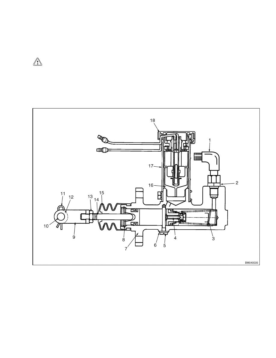
1800 SRM 1076
Master Cylinder
6.
Remove master cylinder from bracket. See Fig-
ure 5.
INSTALL
CAUTION
The brake system uses the same type hydraulic
oil as used in the hydraulic system. Use of auto-
motive or other unapproved fluids can damage
the brake system.
1.
Position master cylinder to bracket and align
mounting holes.
Install two socket-head capscrews, washers,
lockwashers, and nuts securing master cylinder
to bracket.
3.
Install the brake supply line to the elbow fitting
on top of the master cylinder.
4.
Attach the master cylinder to the brake pedal us-
ing the clevis pin and a cotter pin. Adjust linkage
if necessary. See Adjustments, Adjust Linkage.
5.
Bleed air from the brake system. See Adjust-
ments, Bleed the Brake System.
1.
ELBOW FITTING
2.
O-RING FITTING
3.
SPRING
4.
VALVE ROD
5.
STOP PIN
6.
O-RING AND GASKET
7.
CYLINDER HOUSING
8.
STOP PLATE
9.
CLEVIS
10. CLEVIS PIN
11. COTTER KEY
12. WASHER
13. JAM NUT
14. PUSH ROD
15. RUBBER BOOT
16. FILTER
17. RESERVOIR
18. INDICATOR ASSEMBLY
Figure 5. Master Cylinder
5

Brake Lines
1800 SRM 1076
ADJUSTMENTS
Bleed the Brake System
CAUTION
The brake system uses the same type hydraulic
oil as used in the hydraulic system. Use of auto-
motive or other unapproved fluids can damage
the brake system.
When the brake system is operating properly, the
brake pedal will have back pressure that will stop
the pedal before it can be pressed to the end of its
mechanical travel limit. A brake system that has
air present may have some back pressure but not
enough to stop the pedal before reaching its mechan-
ical travel limit. The pedal may feel soft and incon-
sistent (spongy) and must be bled before operating
the lift truck.
NOTE:
Bleeding air from the brake system requires
two technicians.
One technician must sit in the
seat and operate the brake pedal while the other
opens and closes the brake bleed valve located on
the transaxle housing.
To bleed air from the brake system:
1.
Remove the floor plates and check that the mas-
ter cylinder reservoir is full of hydraulic oil.
2.
One technician must sit in the seat and repeat-
edly press and release (pump) the brake pedal to
increase the back pressure. The brake pedal may
become harder to press as this occurs.
3.
When back pressure seems to be at the maxi-
mum, the technician must press and hold the
pedal as far as it will go.
4.
The second technician must slowly loosen the
bleed valve on one of the transaxle housings
between the wheel and the frame. Air and hy-
draulic oil should bubble from the valve until the
pedal is pressed to its mechanical travel limit.
5.
The pedal should be held in this position while
the valve is retightened.
6.
Repeat Step 2 through Step 5 until hydraulic oil
with no air (bubbles) flows from the valve. Check
the hydraulic oil level in the master cylinder ev-
ery cycle and fill reservoir as necessary.
7.
Perform Step 2 through Step 5 on the other
transaxle until all air has been bled from the
system.
Adjust Linkage
To adjust the master cylinder linkage:
1.
Loosen the jam nut on the plunger shaft.
2.
Remove the cotter pin from the clevis pin and
remove the clevis pin.
3.
Turn the plunger shaft until the hole in the clevis
aligns with the mounting hole in the brake pedal.
4.
Install the clevis pin through the clevis and
mounting hole in the brake pedal. Secure with
cotter pin.
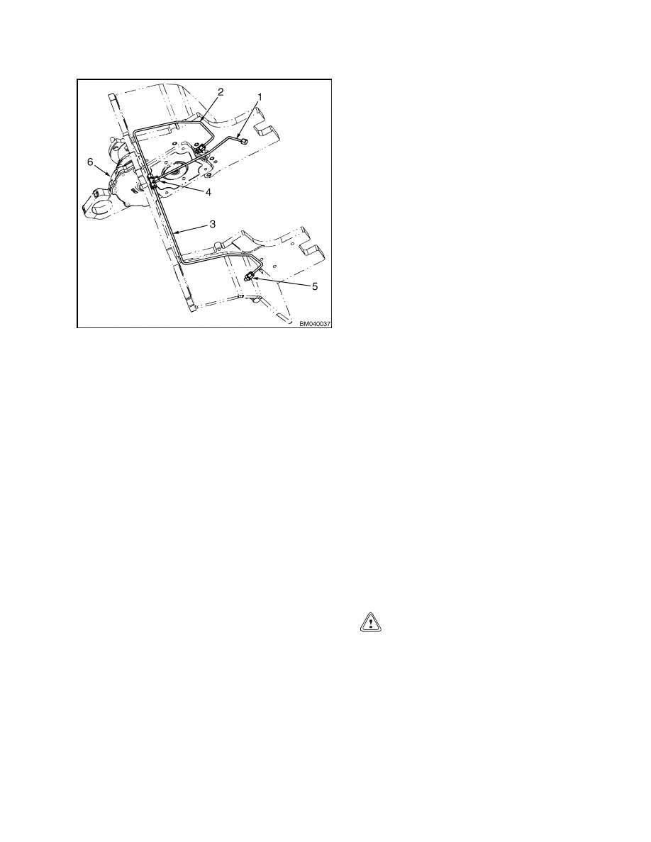
Brake Lines
WARNING
Do not try to find hydraulic leaks by putting
hands on pressurized components. Hydraulic
oil can be injected into the body, resulting in
serious injury.
Hydraulic pressure is transferred from the master
cylinder to the transaxles through brake lines. These
are metal tubes filled with hydraulic oil connected by
hydraulic fittings. Brake lines run below the floor
plates, from the master cylinder to a tee fitting lo-
cated near the front of the frame. They continue from
there as separate left hand (LH) and right hand (RH)
lines through the frame to a fitting on each transaxle.
The drive wheel may be removed to access this con-
nection. See Figure 6.
6
1800 SRM 1076
Parking Brake
Figure 6. Brake Lines
Legend for Figure 6
1.
MAIN LINE
2.
RH LINE
3.
LH LINE
4.
TEE FITTING
5.
FITTING
6.
TRANSAXLE
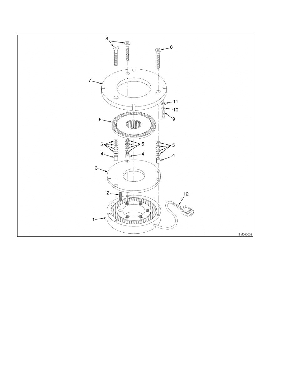
Parking Brake
The
parking
brake
consists
of
two
identical
spring-applied/electrically-released brakes mounted
directly to the drive motors. The controller breaks
the power supply to the brake coils, engaging the
parking brake when the truck is stopped. Pressing
the emergency disconnect will apply the parking
brake immediately in any mode of operation. The
parking brakes may be released for towing by con-
necting the two brake release connectors located
near the right front fender beside the brake diode
assembly on the wiring harness.
Connecting the
connectors energizes the brake coil, releasing the
friction disk.
The following procedures detail the
removal, disassembly, assembly, and installation
procedures for the parking brakes.
Refer to Fig-
ure 7.
REMOVE
1.
Raise and safety chain the mast to prevent unex-
pected movement while working under the mast.
See the section Periodic Maintenance 8000
SRM 1079 for instructions on properly safety
chaining the mast.
2.
Turn key switch to the OFF position and discon-
nect the battery.
3.
Block the wheels of the truck to prevent unex-
pected movement.
4.
Disconnect the parking brake wiring harness
near the parking brake assembly.
5.
Remove the four capscrews (9), lockwashers (10),
and washers (11) securing the brake assembly to
the drive motor.
6.
Slide brake assembly from the motor shaft.
DISASSEMBLE
1.
Remove the parking brake from the drive motor.
See Remove. Place on a clean workbench with
the mounting plate facing up.
Remove three countersunk, socket-head screws
from the mounting plate of the brake assembly.
CAUTION
Be sure to collect all of the spacers. Make a note
of orientation for proper assembly.
3.
Lift mounting plate from brake assembly and col-
lect spacers.
4.
Remove friction disc. Inspect disc for wear. Re-
place if necessary.
5.
Inspect mounting plate and pressure plate for ex-
cessive wear. Replace if necessary.
7
Parking Brake
1800 SRM 1076
1.
BRAKE COIL
2.
SPRINGS
3.
PRESSURE PLATE
4.
SPACERS
5.
SHIMS
6.
FRICTION DISK
7.
MOUNTING PLATE
8.
COUNTERSUNK SCREWS
9.
CAPSCREWS
10. LOCKWASHERS
11. WASHERS
12. WIRING HARNESS
Figure 7. Parking Brake
NOTE:
If only replacing the friction disc and/or
mounting plate, no more disassembly is required.
6.
Remove the pressure plate from the assembly.
Collect the three spacers.
7.
Remove and inspect the springs from the brake
coil. Replace ALL springs if any show damage.
8.
Replace brake coil if necessary.
8

1800 SRM 1076
Troubleshooting
ASSEMBLE
1.
Place brake coil on a clean workbench with the
spring holes facing up.
2.
Install springs into the spring holes in brake coil.
3.
Position pressure plate on top of the springs and
align holes with the brake coil mounting holes.
4.
Install new friction disk onto pressure plate with
splined hub side down.
5.
Install spacers into pressure plate and position
shims on top of spacers as removed.
6.
Carefully position mounting plate on top of as-
sembly with mounting holes aligned as not to dis-
turb the shims.
7.
Install three countersunk mounting screws
through mounting plate, shims, spacers, and
pressure plate into the brake coil.
INSTALL
1.
Position the brake assembly onto the drive mo-
tor shaft and secure to the motor housing using
four capscrews (9), lockwashers (10), and wash-
ers (11).
2.
Install brake wiring harness.
3.
Remove safety chains from the mast. See the sec-
tion Periodic Maintenance 8000 SRM 1079 for
instructions on properly removing safety chains
from the mast.
4.
Remove blocks from the wheels.
5.
Connect the battery. Sit in the seat and turn key
switch to the ON position. Listen for the parking
brakes to release. Check for proper operation.
Troubleshooting
PROBLEM
POSSIBLE CAUSE
PROCEDURE OR ACTION
Brake pedal is hard to push.
The linkage for the brake pedal
needs adjustment.
Adjust or replace linkage.
Internal transaxle damage.
Troubleshoot the transaxles.
Brake pedal travels too far.
Air is in the brake system.
Bleed air from system.
The linkage for the brake pedal is
wrong.
Adjust or replace linkage.
The brake system has a leak.
Tighten connections and monitor
closely.
Brakes make too much noise.
Internal transaxle damage.
Troubleshoot the transaxles.
Service brakes do not oper-
ate equally.
A brake line has a restriction.
Clean out brake line.
Parking brake is dragging.
Adjust or repair park brake.
Internal transaxle damage.
Troubleshoot the transaxles.
9

Troubleshooting
1800 SRM 1076
PROBLEM
POSSIBLE CAUSE
PROCEDURE OR ACTION
Service brakes do not re-
lease.
Damage to system from incorrect
brake fluid.
Remove and clean entire system,
then repair damage.
Parking brake is not releasing.
Troubleshoot parking brake.
Internal transaxle damage.
Troubleshoot the transaxles.
Parking brake will not re-
lease.
Key switch is in the OFF position.
Turn key switch to the ON position.
Battery is not connected or is dis-
charged.
Connect or clean battery connections.
Charge if necessary.
Wiring or controller malfunction(s).
Refer to wiring diagrams.
Excessive wear.
Adjust air gap between brake coil and
pressure plate to 0.30 to 0.46 mm
(0.012 to 0.018 in.)
by adjusting
shims or replacing worn components.
Brake coil is defective.
Check brake coil resistance. Resis-
tance should read 32.5 ohms ±10%.
Replace brake assembly or coil if nec-
essary.
Parking brake will not apply.
Brake override connector is in place.
Disconnect override connector and
connect to brake connector.
Air gap is too large.
Replace the brake assembly.
Internal
mechanical
damage
to
brake.
Repair or replace the brake assembly.
Parking brake does not hold
truck loaded to specification.
Oil or grease on the friction surfaces.
Clean the brake assembly.
Friction surfaces are worn out.
Repair the brake assembly.
Springs are too weak.
Repair the brake assembly.
10


TECHNICAL PUBLICATIONS
1800 SRM 1076
3/04 Printed in United Kingdom
Document Outline
- toc
Wyszukiwarka
Podobne podstrony:
1554628 1600SRM1075 (03 2004) UK EN
1554631 2000SRM1085 (03 2004) UK EN
897393 1800SRM0452 (02 2004) UK EN
1531815 1800SRM1040 (03 2005) UK EN
1564053 0600SRM1101 (03 2004) UK EN
1482623 1800SRM0803 (03 2000) UK EN
1554626 0100SRM1073 (06 2004) UK EN
1531821 1800SRM1037 (03 2005) UK EN
1554631 2000SRM1085 (03 2004) UK EN
1564283 1900SRM1107 (01 2004) UK EN
więcej podobnych podstron