FRAME
H6.00-7.00XL (H135-155XL) [F006, G006]
PART NO. 897104
100 SRM 322

SAFETY PRECAUTIONS
MAINTENANCE AND REPAIR
• When lifting parts or assemblies, make sure all slings, chains, or cables are correctly
fastened, and that the load being lifted is balanced. Make sure the crane, cables, and
chains have the capacity to support the weight of the load.
• Do not lift heavy parts by hand, use a lifting mechanism.
• Wear safety glasses.
• DISCONNECT THE BATTERY CONNECTOR before doing any maintenance or repair
on electric lift trucks. Disconnect the battery ground cable on internal combustion lift
trucks.
• Always use correct blocks to prevent the unit from rolling or falling. See HOW TO PUT
THE LIFT TRUCK ON BLOCKS in the Operating Manual or the Periodic Mainte-
nance section.
• Keep the unit clean and the working area clean and orderly.
• Use the correct tools for the job.
• Keep the tools clean and in good condition.
• Always use HYSTER APPROVED parts when making repairs. Replacement parts
must meet or exceed the specifications of the original equipment manufacturer.
• Make sure all nuts, bolts, snap rings, and other fastening devices are removed before
using force to remove parts.
• Always fasten a DO NOT OPERATE tag to the controls of the unit when making repairs,
or if the unit needs repairs.
• Be sure to follow the WARNING and CAUTION notes in the instructions.
• Gasoline, Liquid Petroleum Gas (LPG), Compressed Natural Gas (CNG), and Diesel fuel
are flammable. Be sure to follow the necessary safety precautions when handling these
fuels and when working on these fuel systems.
• Batteries generate flammable gas when they are being charged. Keep fire and sparks
away from the area. Make sure the area is well ventilated.
NOTE:
The following symbols and words indicate safety information in this
manual:
WARNING
Indicates a condition that can cause immediate death or injury!
CAUTION
Indicates a condition that can cause property damage!

Frame
Table of Contents
TABLE OF CONTENTS
General ...............................................................................................................................................................
Description .........................................................................................................................................................
Counterweight Repair .......................................................................................................................................
Remove ...........................................................................................................................................................
Install .............................................................................................................................................................
Hood Repair........................................................................................................................................................
Remove ...........................................................................................................................................................
Install .............................................................................................................................................................
Overhead Guard Repair ....................................................................................................................................
Remove ...........................................................................................................................................................
Install .............................................................................................................................................................
Operator Restraint System Repair ...................................................................................................................
Hydraulic Tank Repair ......................................................................................................................................
Remove ...........................................................................................................................................................
Inspect ............................................................................................................................................................
Small Leaks Repair .......................................................................................................................................
Large Leaks Repair .......................................................................................................................................
Clean ..............................................................................................................................................................
Steam Method............................................................................................................................................
Chemical Solution Method........................................................................................................................
Other Methods of Preparation for Repair ....................................................................................................
Install .............................................................................................................................................................
Fuel Tank Repair ...............................................................................................................................................
Remove ...........................................................................................................................................................
Repair .............................................................................................................................................................
Install .............................................................................................................................................................
Radiator Repair..................................................................................................................................................
Remove ...........................................................................................................................................................
Install .............................................................................................................................................................
Engine Repair ....................................................................................................................................................
Remove ...........................................................................................................................................................
Install .............................................................................................................................................................
Throttle Pedal Adjustment................................................................................................................................
Perkins 1104C-44(RE) Diesel Engine ...........................................................................................................
Safety Labels ......................................................................................................................................................
Cab Repair..........................................................................................................................................................
Cab, Replace...................................................................................................................................................
Window, Replace ............................................................................................................................................
Windshield Wipers and Heater .....................................................................................................................
This section is for the following models:
H6.00-7.00XL (H135-155XL) [F006, G006]
©2004 HYSTER COMPANY
i

"THE
QUALITY
KEEPERS"
HYSTER
APPROVED
PARTS
100 SRM 322
Description
General
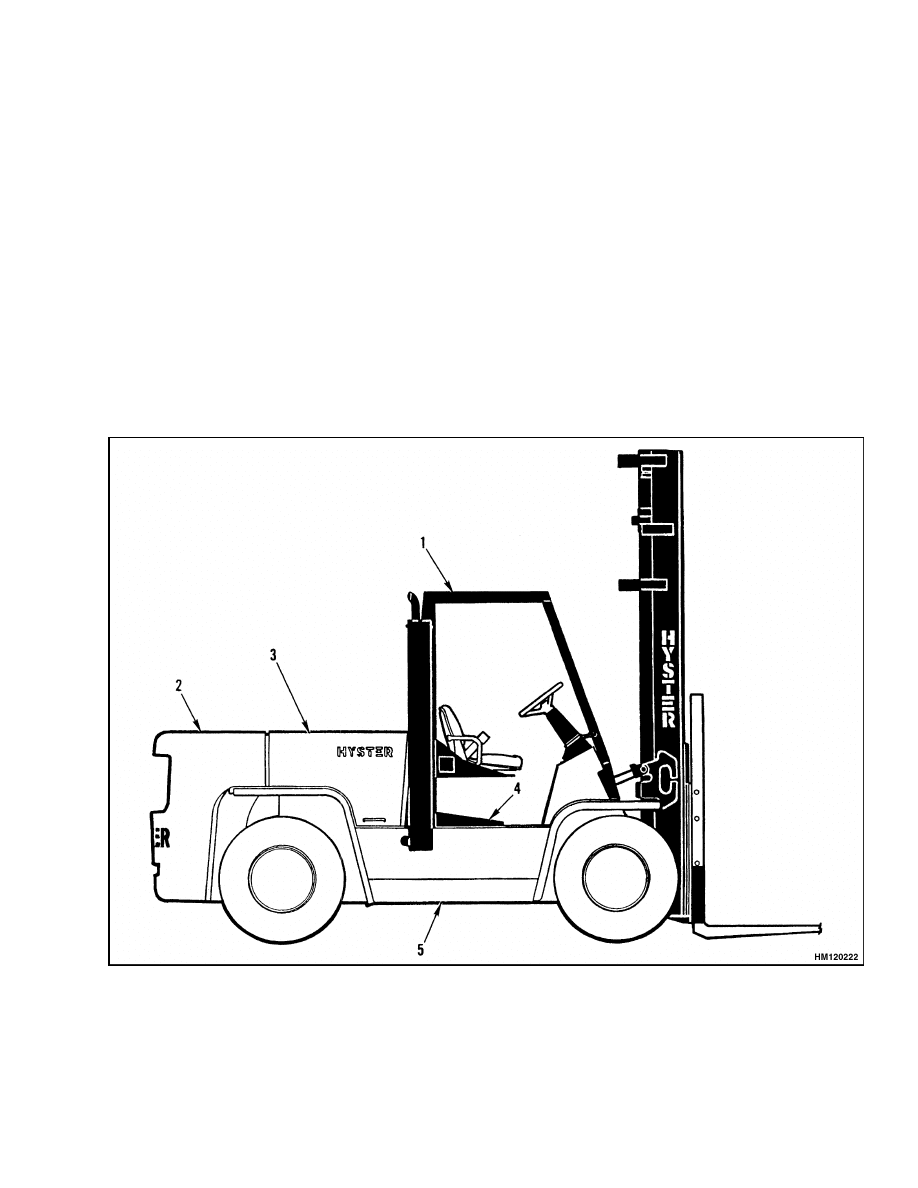
This section has the description of the frame and
some connected parts. See Figure 1. Procedures for
the removal and installation of the counterweight,
hood, overhead guard, and engine are under Coun-
terweight Repair, Hood Repair, Overhead Guard Re-
pair, and Engine Repair. Checks for the operator re-
straint system and procedures for the repair of tanks
and replacement of safety labels are included.
Description
The frame is one weldment and includes the hy-
draulic tank and the fuel tank for gasoline and
diesel fuel.
There is a counterweight for each capacity of lift
truck. The counterweights are similar, but are dif-
ferent weights.
An overhead guard is fastened to the frame of the lift
truck. The overhead guard has the mounts for the
seat plate and the hood.
The hood is connected at mounts on the cowl and the
frame.
1.
OVERHEAD GUARD
2.
COUNTERWEIGHT
3.
HOOD
4.
FLOOR PLATE
5.
FRAME
Figure 1. Frame and Connected Parts
1
Counterweight Repair
100 SRM 322
Counterweight Repair
REMOVE
WARNING
The lift truck must be put on blocks for some
types of maintenance and repair. The removal
of the following assemblies will cause large
changes in the center of gravity:
upright,
drive axle, engine and transmission, and coun-
terweight. When the lift truck is put on blocks,
put additional blocks in the following posi-
tions to maintain stability:
a. Before removing the upright and drive axle,
put blocks under the counterweight so the
lift truck cannot fall backward.
b. Before removing the counterweight, put
blocks under the upright assembly so the
lift truck cannot fall forward.
The surface must be solid, even, and level when
the lift truck is put on blocks. Make sure that
any blocks used to support the lift truck are
solid, one-piece units.
WARNING
Do not operate the lift truck if the capscrew for
the counterweight is not installed. When the
capscrew is removed, the counterweight can
fall from the lift truck.
1.
Remove the grille and the cover for the hydraulic
pump.
2.
Remove the bracket for the rear hood mount from
the frame. Put a block between the hood and the
radiator.
WARNING
Make sure any lifting devices have the correct
capacity for the parts being removed.
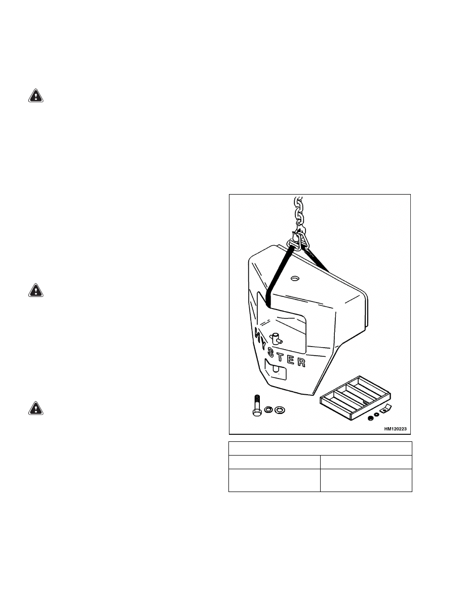
3.
Put a lifting strap through the hole in the coun-
terweight. Connect a lifting device to the strap.
Remove the bolt that holds the counterweight to
the frame. See Figure 2.
4.
Lift the counterweight from the frame. Put the
counterweight in a position so it has stability.
INSTALL
1.
Connect a strap and lifting device to the coun-
terweight. Lift the counterweight into position
on the frame. Make sure the counterweight is in
position on the mounts.
2.
Install the bolt for the counterweight. Install the
cover for the hydraulic pump. Install the grille.
3.
Install the bracket for the hood mount. Install
the capscrews for the hood mount. Adjust the
hood as described in the procedures for the hood.
Weight of Counterweights
H6.00XL (H135XL)
H7.00XL (H155XL)
2594 to 2654 kg
(5720 to 5852 lb)
3092 to 3162 kg
(6818 to 6972 lb)
Figure 2. Counterweight
2

100 SRM 322
Overhead Guard Repair
Hood Repair
REMOVE
Remove the hood (both sides) as an assembly. Re-
move the capscrews that hold the hood mount
bracket to the frame. Remove the capscrews that
hold the hood to the bracket on the overhead guard.
Lift the hood from the frame.
INSTALL
Install the hood assembly on the frame. Install the
capscrews that hold the brackets to the frame and
bracket on the overhead guard. If necessary, adjust
the hood as follows:
1.
Loosen the capscrews at the mounts for the hood
assembly. Put the hood assembly in a position
so the center of the hood is in the center of the
counterweight and overhead guard. Tighten the
capscrews.
2.
Adjust the mount (on the frame) and the hood
stops at the rear of the hood so the top of the
hood aligns with the counterweight. Make sure
the hood does not touch the counterweight.
3.
Adjust the other hood stops so they just touch the
sides of the hood when they are closed.
Overhead Guard Repair
REMOVE
WARNING
The lift truck must be put on blocks for some
types of maintenance and repair. The removal
of the following assemblies will cause large
changes in the center of gravity:
upright,
drive axle, engine and transmission, and coun-
terweight. When the lift truck is put on blocks,
put additional blocks in the following posi-
tions to maintain stability:
a. Before removing the upright and drive axle,
put blocks under the counterweight so the
lift truck cannot fall backward.
b. Before removing the counterweight, put
blocks under the upright assembly so the
lift truck cannot fall forward.
The surface must be solid, even, and level when
the lift truck is put on blocks. Make sure that
any blocks used to support the lift truck are
solid, one-piece units.
WARNING
Do not operate the lift truck without the over-
head guard correctly fastened to the lift truck.
Changes that are made by welding or by
drilling holes that are too big in the wrong lo-
cation can reduce the strength of the overhead
guard. See the instructions for Changes to the
Overhead Guard in the Periodic Maintenance
section included with this lift truck.
1.
Remove the hood as an assembly. Disconnect the
hose to the air cleaner. Disconnect the exhaust
system from the overhead guard leg. Remove the
capscrews that hold the brake reservoir to the
overhead guard. If a cab is installed, disconnect
the wiring harness for the cab. Lift the doors
from the cab. See Figure 3.
2.
Connect a lifting device to the top of the overhead
guard. Remove the capscrews (in the engine com-
partment) that hold the overhead guard to the
frame. Remove the capscrews that hold the over-
head guard to the cowl. Lift the overhead guard
from the lift truck.
INSTALL
1.
Connect a lifting device to the top of the overhead
guard. Put the overhead guard in position on the
lift truck. See Figure 3.
2.
Make sure the rubber bushings are in the mount
holes at the rear of the overhead guard. Install
the capscrews at the rear of the overhead guard.
Install the capscrews that hold the overhead
guard to the cowl and tighten them to 285 N•m
(210 lbf ft). Connect the wiring harness for the
cab. Install the doors for the cab.
3.
Connect the hose for the air cleaner. Connect the
exhaust system. Install the brake fluid reservoir.
3
Operator Restraint System Repair
100 SRM 322
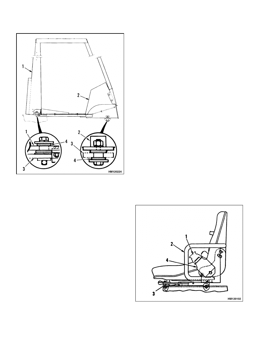
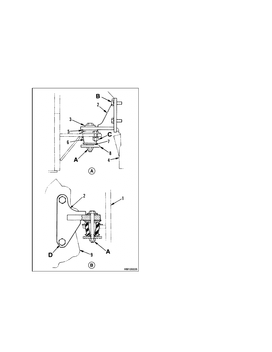
Figure 3. Overhead Guard and Cab Mounting
Legend for Figure 3
1.
OVERHEAD
GUARD
2.
COWL
3.
FRAME
4.
RUBBER BUSHING
Operator Restraint System Repair
The seat belt, hip restraint brackets, seat, and
mounting are all part of the operator restraint sys-
tem. Each item must be checked to make sure it is
attached securely, functions correctly, and is in good
condition.
The end of the seat belt must fasten correctly in the
latch. Make sure the seat belt pulls from the re-
tractor assembly and retracts smoothly. The seat
belt must be in good condition. A seat belt that is
damaged or worn will not give protection when it is
needed.
Make sure the seat rails are not loose. See Figure 4.
The seat rails must lock securely in position, but
move freely when unlocked. The seat rails must be
securely attached to the mounting surface.
Figure 4. Seat Check
4

100 SRM 322
Hydraulic Tank Repair
Legend for Figure 4
1.
SEAT BELT
2.
HIP RESTRAINT
3.
SEAT RAIL
4.
SEAT BELT RETRACTOR
Hydraulic Tank Repair
REMOVE
WARNING
The lift truck must be put on blocks for some
types of maintenance and repair. The removal
of the following assemblies will cause large
changes in the center of gravity: mast, drive
axle, engine and transmission, and the coun-
terweight. When the lift truck is put on blocks,
put additional blocks in the following posi-
tions to maintain stability:
a. Before removing the mast and drive axle,
put blocks under the counterweight so the
lift truck cannot fall backward.
b. Before removing the counterweight, put
blocks under the mast assembly so the lift
truck cannot fall forward.
The surface must be solid, even, and level when
the lift truck is put on blocks. Make sure that
any blocks used to support the lift truck are
solid, one piece units.
1.
Remove the engine and transmission. See En-
gine Repair.
2.
Remove the drain plug and drain the oil from the
tank. Disconnect the hydraulic lines at the tank
and put caps on the open lines.
3.
Remove the hooks that hold the tank to the
frame. Remove the hydraulic tank.
INSPECT
Make a visual inspection of all sides of the tank. In-
spect the welds for cracks and leakage. Check for
wet areas, accumulation of dirt, and loose or miss-
ing paint caused by leakage. Areas of the tank that
are not easily seen can be checked with an inspection
mirror and a light that is approved for locations with
flammable vapors.
SMALL LEAKS REPAIR
Use the following procedure to repair small leaks:
1.
Use steam to clean the area around the leak. Re-
move all paint and dirt around the leak.
WARNING
Do not use tools that can make sparks, heat, or
static electricity. The vapors in the tank can
cause an explosion.
2.
Apply Loctite
®
290 to the leak. Follow the in-
structions of the manufacturer.
LARGE LEAKS REPAIR
1.
Use one of the procedures described under Clean
to clean and prepare the tank for repairs.
2.
Use acceptable welding practices to repair the
tank.
See the American National Standards
Safety In Welding and Cutting AWS Z 49.1 -
1999.
CLEAN
WARNING
Special procedures must be followed when
large leaks or other repairs need welding or
cutting. All work must be done by authorized
personnel. If the tank is cleaned inside of a
building, make sure there is enough ventila-
tion. See the following manuals for additional
information:
• "Safe Practices for Welding and Cutting Con-
tainers that have Held Combustibles" by the
American Welding Society, F4.1 - 1999.
• "Safety in Welding and Cutting," American
National Standard, AWS Z 49.1 - 1999.
When cleaning the tank, do not use solutions that
make dangerous gases at normal temperatures or
when heated. Wear eye and face protection. Protect
the body from burns.
When cleaning with steam, use a hose with a mini-
mum diameter of 19 mm (0.75 in.). Control the pres-
sure of the steam by a valve installed at the nozzle of
5

Hydraulic Tank Repair
100 SRM 322
the hose. If a metal nozzle is used, it must be made of
a material that does not make sparks. Make an elec-
trical connection between the nozzle and the tank.
Connect a ground wire to the tank to prevent static
electricity.
Steam Method
Use the following procedure to clean the tank with
steam:
1.
Remove all the parts from the tank. Install the
drain plug.
2.
Fill the tank 1/4 full with a solution of water and
sodium bicarbonate or sodium carbonate. Mix
0.5 kg (1 lb) per 4 liter (1 gal) of water.
3.
Mix the solution in the tank using air pressure.
Make sure all the surfaces on the inside of the
tank are flushed with the solution. Drain the
tank.
4.
Put steam into the tank until the tank does not
have odors and the metal is hot. Steam vapors
must come out of all openings.
5.
Flush the inside of the tank with boiling water.
Make sure all loose material is removed from the
inside of the tank.
6.
Make an inspection of the inside of the tank. If it
is not clean, repeat Step 4 and Step 5 and make
another inspection. When making inspections,
use a light that is approved for locations with
flammable vapors.
7.
Put plugs in all the openings in the tank. Wait 15
minutes, then remove the inlet and outlet plugs.
Test a sample of the vapor with a special indi-
cator for gas vapors. If the amount of flammable
vapors is above the lower flammable limit, repeat
the cleaning procedures.
Chemical Solution Method
If the tank cannot be cleaned with steam, use the
following procedure:
1.
Mix a solution of water and trisodium phosphate
or a cleaning compound with an alkali base. Fol-
low the instructions given by the manufacturer.
WARNING
Compressed air can move particles so that they
cause injury to the user or to other personnel.
Make sure that the path of the compressed air
is away from all personnel.
Wear protective
goggles or a face shield to prevent injury to the
eyes.
2.
Fill the tank with the cleaning solution. Use com-
pressed air to mix the solution in the tank.
3.
Drain the tank. Flush the inside of the tank with
boiling water. Make sure all the cleaning com-
pound is removed.
4.
Make an inspection of the inside of the tank. If
the tank is not clean, repeat Step 1 to Step 3.
Make another inspection of the tank. When mak-
ing inspections, use a light that is approved for
locations with flammable vapors.
5.
Check the tank for flammable vapors using a
special indicator for gas vapors. If the amount
of flammable vapors is not below the lower
flammable limit, repeat the cleaning procedures.
OTHER METHODS OF PREPARATION FOR
REPAIR
If nitrogen gas or carbon dioxide gas is available, pre-
pare the tank for welding using these gases. See the
manual Safe Practices For Welding and Cutting Con-
tainers That Have Held Combustibles by the Ameri-
can Welding Society, F4.1 - 1999. If these gases are
not available, another method using water can be
used as follows:
1.
Fill the tank with water to just below the point
where the work will be done.
Make sure the
space above the level of the water has a vent.
2.
Use acceptable welding practices to repair the
tank.
See the American National Standard
"Safety In Welding And Cutting" AWS Z 49.1 -
1999.
INSTALL
1.
Put the tank in position in the frame and install
the hooks.
2.
Connect the hydraulic lines to the fittings on the
tank.
3.
Install the engine and transmission.
Fill the
tank with the correct hydraulic oil. Operate the
system and check for leaks and correct operation.
6

100 SRM 322
Radiator Repair
Fuel Tank Repair
REMOVE
WARNING
The lift truck must be put on blocks for some
types of maintenance and repair. The removal
of the following assemblies will cause large
changes in the center of gravity: mast, drive
axle, engine and transmission, and the coun-
terweight. When the lift truck is put on blocks,
put additional blocks in the following posi-
tions to maintain stability:
a. Before removing the mast and drive axle,
put blocks under the counterweight so the
lift truck cannot fall backward.
b. Before removing the counterweight, put
blocks under the mast assembly so the lift
truck cannot fall forward.
The surface must be solid, even, and level when
the lift truck is put on blocks. Make sure that
any blocks used to support the lift truck are
solid, one piece units.
1.
Remove the engine and transmission. See En-
gine Repair.
WARNING
Do not use tools that can make sparks, heat, or
static electricity. The vapors in the tank can
cause an explosion. Clean all fuel spills. Make
sure the fuel from the tank is put in a closed
container.
2.
Remove the drain plug and drain the fuel from
the tank. Disconnect the fuel lines at the tank
and put caps on the openings.
3.
Remove the filler neck from the fuel tank. Re-
move the hooks that hold the tank to the frame.
Remove the fuel tank.
REPAIR
Repair the fuel tank as described in the repair proce-
dures for the hydraulic tank.
INSTALL
1.
Put the tank in position in the frame. Install the
filler neck and the hooks.
2.
Install the engine and transmission. Connect the
fuel lines to the tank.
Radiator Repair
REMOVE
1.
Remove the hood as an assembly.
2.
Drain the coolant from the radiator. Disconnect
the radiator hoses. If equipped, disconnect the
lines from the powershift transmission. Put caps
on the open lines.
3.
Remove the screws that hold the fan shroud to
the radiator. Remove the nuts that hold the ra-
diator to the frame.
4.
Remove the radiator.
INSTALL
1.
Put the fan shroud in position over the fan. In-
stall the radiator to the mounts on the frame. In-
stall the fan shroud on the radiator.
2.
Connect the radiator hoses and lines for the pow-
ershift transmission.
3.
Install the hood. Fill the radiator with coolant,
then operate the engine and check for leaks.
7

Engine Repair
100 SRM 322
Engine Repair
REMOVE
WARNING
The lift truck must be put on blocks for some
types of maintenance and repair. The removal
of the following assemblies will cause large
changes in the center of gravity: mast, drive
axle, engine and transmission, and the coun-
terweight. When the lift truck is put on blocks,
put additional blocks in the following posi-
tions to maintain stability:
a. Before removing the mast and drive axle,
put blocks under the counterweight so the
lift truck cannot fall backward.
b. Before removing the counterweight, put
blocks under the mast assembly so the lift
truck cannot fall forward.
The surface must be solid, even, and level when
the lift truck is put on blocks. Make sure that
any blocks used to support the lift truck are
solid, one-piece units.
1.
Disconnect the cables at the battery.
2.
Remove the hood. Remove the air cleaner assem-
bly. Disconnect the brake fluid reservoir from
the bracket. If necessary, remove the overhead
guard. See Overhead Guard Repair.
3.
Drain the coolant from the cooling system. Re-
move the radiator. See Radiator Repair.
4.
Disconnect the drive shaft for the hydraulic
pump at the crankshaft pulley.
5.
Disconnect the exhaust system.
6.
Disconnect the hydraulic lines at the steering
pump. Put caps on the open lines.
7.
Disconnect fuel lines and the throttle linkage.
8.
Disconnect wires and wiring harnesses at the en-
gine.
9.
Connect a lifting device to the engine. Make sure
the lifting device has a capacity of at least 450 kg
(1000 lb) (engine only).
10. On units with a powershift transmission, remove
the capscrews that hold the torque converter to
the flywheel. Put blocks under the output end
of the transmission. Remove the capscrews that
connect the engine to the flywheel housing.
11. Remove the capscrews that hold the mount at the
fan end of the engine to the frame.
12. Carefully lift the engine from the frame. Make
sure all the connections have been removed.
Make sure the torque converter stays with the
transmission and does not fall.
INSTALL
1.
Connect a lifting device to the engine.
Make
sure the lifting device has a capacity of 450 kg
(1000 lb).
2.
Make sure the drive plate is installed on the
torque converter. Lubricate the pilot bushing in
the flywheel with multipurpose grease. Install
the engine in the frame. Make sure the torque
converter stays in the transmission. Fit the fly-
wheel on the pilot of the torque converter. Install
the capscrews that hold the flywheel housing to
the engine. Tighten the capscrews to 31 N•m
(23 lbf ft).
3.
Install the capscrews and washers for the engine
mount at the fan end of the engine. Install the
capscrews and adjust the mounts at the flywheel
end of the engine. Tighten the capscrews to the
correct torque values as shown on Figure 5.
4.
Install the capscrews that hold the drive plate
for the torque converter to the flywheel. Tighten
the capscrews to 44 N•m (32 lbf ft) on all units.
Remove the lifting device.
5.
Connect the wiring harness and wires at the en-
gine.
6.
Connect the throttle linkage and fuel lines at the
engine.
7.
Connect the pipe for the exhaust system.
8
100 SRM 322
Engine Repair
8.
Connect the drive shaft for the hydraulic pump.
9.
See Radiator Repair, and install the radiator.
Connect radiator hoses and cooling line for the
powershift transmission.
10. See Overhead Guard Repair, and install the over-
head guard. Install the brake fluid reservoir on
the bracket. Install the hood. Connect the cables
at the battery.
Figure 5. Engine Mounts
Legend for Figure 5
NOTE: A = 40 N•m (30 lbf ft) TORQUE
B = 56 N•m (41 lbf ft) TORQUE
C = 50 N•m (37 lbf ft) TORQUE
D = 165 N•m (122 lbf ft) TORQUE.
A. FAN END OF ENGINE (DIESEL SHOWN)
B. FLYWHEEL END OF ENGINE
1.
FRAME
2.
MOUNT BRACKET
3.
WASHER
4.
ENGINE
5.
OVERLOAD WASHER
6.
ENGINE MOUNT
7.
WASHER*
8.
REBOUND WASHER
9.
TORQUE CONVERTER OR CLUTCH HOUSING
*USE AS NECESSARY TO ALIGN U-JOINT TO
WITHIN 0.5 to 1.5 mm (0.02 to 0.06 in.) OF TRUE
VERTICAL ALIGNMENT
9
Throttle Pedal Adjustment
100 SRM 322
Throttle Pedal Adjustment
PERKINS 1104C-44(RE) DIESEL ENGINE
NOTE: The procedures below are for lift trucks
equipped with the Perkins 1104C-44(RE) Diesel
Engine. If your lift truck has either a gas or LPG
engine, see the section LPG Fuel System 900 SRM
348 for the procedures to adjust the throttle linkage.
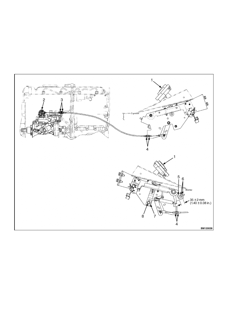
1.
Adjust the cable adjustment nuts to allow for a
3.0 mm (0.12 in.) maximum of free play on the
throttle cable length. See Figure 6. Secure cable
length by tightening cable locknuts.
2.
Set pedal stop to 35 ±2 mm (1.40 ±0.08 in.). Se-
cure in place with pedal stop jam nuts.
NOTE: THE MONOTROL PEDAL IS SHOWN. THE ADJUSTMENT PROCEDURES FOR THE ACCELERATOR
PEDAL ARE THE SAME.
1.
MONOTROL PEDAL
2.
DIESEL INJECTOR PUMP
3.
CABLE ADJUSTMENT NUTS
4.
CABLE LOCKNUTS
5.
PEDAL STOP JAM NUTS
6.
PEDAL STOP
7.
UP POSITION PEDAL STOP
8.
CAPSCREW
Figure 6. MONOTROL and Accelerator Pedal Adjustment
10
100 SRM 322
Safety Labels
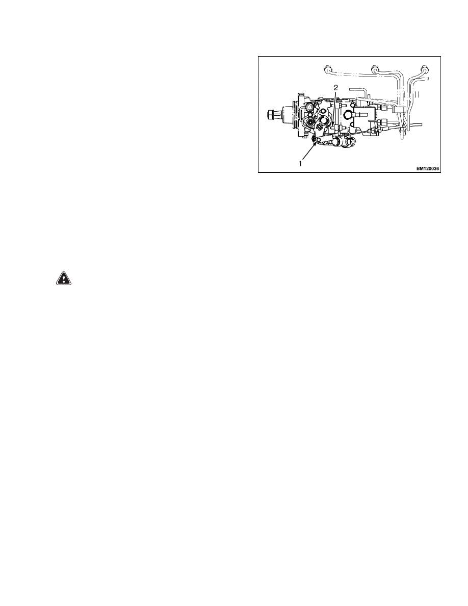
3.
With the pedal against the stop, adjust the throt-
tle cable to ensure that the diesel injector pump
is at full power (the injection pump lever is touch-
ing the lever stop in Figure 7).
4.
Release the throttle pedal and adjust the up posi-
tion pedal stop until the tension is removed from
the cable when the injection pump lever is re-
turned to the idle position. Tighten up position
pedal stop with capscrew. See Figure 6.
NOTE: DIESEL INJECTOR PUMP IS SHOWN IN THE
IDLE POSITION.
1.
INJECTION PUMP LEVER
2.
LEVER STOP
Figure 7. Diesel Injector Pump
Safety Labels
WARNING
Safety labels are installed on the lift truck to
give information about operation and possible
hazards. It is important that all safety labels
are installed on the lift truck and can be read.
DO NOT add to or modify the lift truck. Any
change to the lift truck, the tires, or its equip-
ment can change the lifting capacity. The lift
truck must be rated as equipped and the name-
plate must show the new capacity rating. Con-
tact your dealer for Hyster lift trucks for a re-
placement nameplate.
Cleaning solvents can be flammable and toxic
and cause skin irritation. When using cleaning
solvents, always follow the recommendations
of the manufacturer.
If a label must be replaced, use the following proce-
dure to install a new label:
1.
Make sure the surface is dry and has no oil or
grease. Do not use solvent on new paint. Clean
the surface of old paint with a cleaning solvent.
2.
Remove the paper from the back of the label. Do
not touch the adhesive surface.
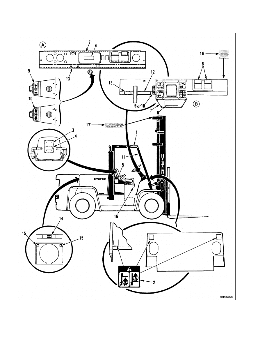
3.
Carefully hold the decal in the correct position
above the surface. See Figure 8. The label cannot
be moved after it touches the surface. Put the
label on the surface. Make sure all air is removed
from under the label and the corners and edges
are tight.
11
Safety Labels
100 SRM 322
Figure 8. Label Positions
12

100 SRM 322
Cab Repair
Legend for Figure 8
A. EARLY MODELS
B. LATE MODELS
1.
WARNING FOR SAFETY
2.
MAST SAFETY (2)
3.
CASE FOR OPERATING MANUAL
4.
REPLACE OPERATING MANUAL (NOT FOR
ENGLISH SPEAKING COUNTRIES)
5.
NO RIDERS (2)
6.
DEALER WARNING LABEL
7.
NAMEPLATE
8.
LABEL FOR CONTROL LEVERS
9.
LABEL FOR RANGE LEVER (POWERSHIFT
TRANSMISSION)
10. LABEL FOR DIRECTION CONTROL LEVER
11. OPERATOR RESTRAINT (FOR EQUIPPED
UNITS) OR TIPOVER WARNING (FOR OTHER
UNITS)
12. PARKING BRAKE WARNING
13. INSPECTION PLATE, UL
14. FAN WARNING
15. FAN WARNING
16. FLAMMABLE LP GAS
17. MAST WARNING LABEL
18. RADIAL TIRE WARNING LABEL
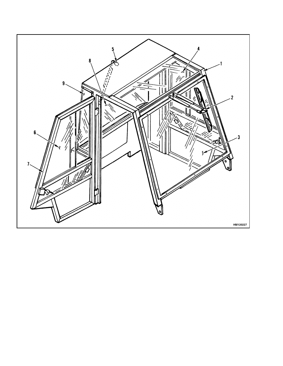
Cab Repair
Some lift trucks are equipped with a cab. See Fig-
ure 9. The cab has an overhead guard with doors
and windows. The cab has front and rear windshield
wipers and a heater with a fan. The heater is on a
mount on the instrument panel.
CAB, REPLACE
NOTE:
Disconnect all electric wires.
Remove any
other parts between the cab and the lift truck. Re-
move the cab assembly. Use a crane to lift the cab.
Each leg of the cab assembly is attached to the lift
truck frame with a bolt, washers, and rubber pads.
See Figure 3. If necessary, the cab can be replaced as
a complete unit.
WINDOW, REPLACE
The front, rear, and side windows and window frames
are replaced as single units. A window and frame are
not available as separate units. The top window has
no frame.
WARNING
All windows installed in the cab are made of
special material, not regular glass. New win-
dows must meet the material and thickness
specifications of the original windows.
See
Table 1 for the correct window materials.
1.
Remove the rivets or screws that hold the win-
dow frames to the cab assembly. Use a chisel
and a punch if necessary to completely remove
the rivets.
2.
Have a dealer for Hyster lift trucks or a qualified
supplier of glass, replace any damaged window
or frame parts. Make sure the material and the
thickness of the window parts are according to
the specifications in Table 1.
3.
Install the new window in the position on the cab.
Align the window frame with the opening in the
cab frame or door frame. Use a drill to make new
holes for the fasteners if new window frames are
used. Some windows are installed with an adhe-
sive/sealant (Hyster part no. 318352). Before ap-
plying the adhesive/sealant, clean the area with
window weld primer (Hyster part no. 365337).
WINDSHIELD WIPERS AND HEATER
WARNING
When the heater hoses must be replaced in the
cab, make sure to use heater hoses of the cor-
rect material and size. All hoses must conform
to SAE Specification 20R3 Class C or 20R3 Class
D-2.
Observe the previous WARNING when replacing
heater hoses in the cab.
13
Cab Repair
100 SRM 322
1.
CAB FRAME ASSEMBLY
2.
WIPER ASSEMBLY (FRONT)
3.
WINDSHIELD
4.
TOP WINDOW
5.
WIPER ASSEMBLY (REAR)
6.
DOOR WINDOW (RH)
7.
DOOR ASSEMBLY (RH)
8.
REAR WINDOW
9.
SIDE WINDOW
Figure 9. Cab
14

100 SRM 322
Cab Repair
Table 1. Material Specifications for Cab Windows
Thickness
Location of
Window
Hyster
Part No.
Material Specification
mm
in.
Front
1375978
Clear Laminated Safety Glass per ANSI Z26.1
AS1
5.9 to 7.5
0.23 to 0.30
Rear
1319365
Clear Laminated Tempered Safety Glass per
ANSI Z26.1 AS2
5.6 to 6.8
0.22 to 0.27
Side
1319364
Clear Laminated Tempered Safety Glass per
ANSI Z26.1 AS2
5.6 to 6.8
0.22 to 0.27
Doors
RH
1375982
Clear Tempered Safety Glass per ANSI Z26.1 AS2
5.6 to 6.2
0.22 to 0.24
LH
1375981
Clear Tempered Safety Glass per ANSI Z26.1 AS2
5.6 to 6.2
0.22 to 0.24
Top
1321868
Clear Lexan MR 5004 or Equivalent
6.0
0.24
15

NOTES
____________________________________________________________
____________________________________________________________
____________________________________________________________
____________________________________________________________
____________________________________________________________
____________________________________________________________
____________________________________________________________
____________________________________________________________
____________________________________________________________
____________________________________________________________
____________________________________________________________
____________________________________________________________
____________________________________________________________
____________________________________________________________
____________________________________________________________
____________________________________________________________
____________________________________________________________
____________________________________________________________
____________________________________________________________
____________________________________________________________
16


TECHNICAL PUBLICATIONS
100 SRM 322
5/04 (11/03)(3/97)(4/90)(5/86) Printed in United Kingdom
Document Outline
- toc
- tables
Wyszukiwarka
Podobne podstrony:
897390 0100SRM0449 (05 2004) UK EN
897506 4000SRM0521 (05 2004) UK EN
897067 1400SRM0285 (05 2004) UK EN
910460 1600SRM0258 (05 2004) UK EN
1566270 0100SRM1118 (08 2004) UK EN
1467764 8000SRM0738 (05 2004) UK EN
1554626 0100SRM1073 (06 2004) UK EN
897559 0100SRM0545 (06 2004) UK EN
1553986 8000SRM1083 (05 2004) UK EN
897455 0100SRM0486 (05 1992) UK EN
897506 4000SRM0521 (05 2004) UK EN
więcej podobnych podstron