STEERING SYSTEM
J1.6-2.0XMT (J30-40ZT) [J160]
PART NO. 1554628
1600 SRM 1075

SAFETY PRECAUTIONS
MAINTENANCE AND REPAIR
• When lifting parts or assemblies, make sure all slings, chains, or cables are correctly
fastened, and that the load being lifted is balanced. Make sure the crane, cables, and
chains have the capacity to support the weight of the load.
• Do not lift heavy parts by hand, use a lifting mechanism.
• Wear safety glasses.
• DISCONNECT THE BATTERY CONNECTOR before doing any maintenance or repair
on electric lift trucks.
• Disconnect the battery ground cable on internal combustion lift trucks.
• Always use correct blocks to prevent the unit from rolling or falling. See HOW TO PUT
THE LIFT TRUCK ON BLOCKS in the Operating Manual or the Periodic Mainte-
nance section.
• Keep the unit clean and the working area clean and orderly.
• Use the correct tools for the job.
• Keep the tools clean and in good condition.
• Always use HYSTER APPROVED parts when making repairs. Replacement parts
must meet or exceed the specifications of the original equipment manufacturer.
• Make sure all nuts, bolts, snap rings, and other fastening devices are removed before
using force to remove parts.
• Always fasten a DO NOT OPERATE tag to the controls of the unit when making repairs,
or if the unit needs repairs.
• Be sure to follow the WARNING and CAUTION notes in the instructions.
• Gasoline, Liquid Petroleum Gas (LPG), Compressed Natural Gas (CNG), and Diesel fuel
are flammable. Be sure to follow the necessary safety precautions when handling these
fuels and when working on these fuel systems.
• Batteries generate flammable gas when they are being charged. Keep fire and sparks
away from the area. Make sure the area is well ventilated.
NOTE:
The following symbols and words indicate safety information in this
manual:
WARNING
Indicates a condition that can cause immediate death or injury!
CAUTION
Indicates a condition that can cause property damage!

Steering System
Table of Contents
TABLE OF CONTENTS
Introduction........................................................................................................................................................
General ...........................................................................................................................................................
Discharging the Capacitors...........................................................................................................................
Description of Operation....................................................................................................................................
Steering Pressure Check ...................................................................................................................................
Operation Check ................................................................................................................................................
Steering Wheel and Column..............................................................................................................................
Steering Column Covers................................................................................................................................
Remove.......................................................................................................................................................
Install .........................................................................................................................................................
Steering Column Components ......................................................................................................................
Remove.......................................................................................................................................................
Install .........................................................................................................................................................
Steering Control Unit Assembly .......................................................................................................................
Power Steering Pump and Motor ......................................................................................................................
Description .....................................................................................................................................................
Remove ...........................................................................................................................................................
Install .............................................................................................................................................................
Disassemble ...................................................................................................................................................
Assemble ........................................................................................................................................................
Steering Actuator Components .........................................................................................................................
Steer Tire and Wheel Assembly....................................................................................................................
Remove.......................................................................................................................................................
Install .........................................................................................................................................................
Wheel Hub Assembly.....................................................................................................................................
Remove.......................................................................................................................................................
Install .........................................................................................................................................................
Steering Axle Assembly.................................................................................................................................
Remove.......................................................................................................................................................
Clean ..........................................................................................................................................................
Install .........................................................................................................................................................
Troubleshooting..................................................................................................................................................
This section is for the following models:
J1.6-2.0XMT (J30-40ZT) [J160]
©2004 HYSTER COMPANY
i

"THE
QUALITY
KEEPERS"
HYSTER
APPROVED
PARTS
1600 SRM 1075
Introduction
Introduction
GENERAL
This section contains the description and repair pro-
cedures for the steering system. Components cov-
ered are the steering wheel and column assembly,
steering control unit, pump and motor assembly, and
steering actuator. Some parts associated with the
steering system are not covered in this section be-
cause they are more closely associated with other sys-
tems. See the following list for information not in-
cluded in this section.
See the section Periodic Maintenance 8000
SRM 1079 for information on the regular sched-
uled maintenance.
See the section Electrical System 2200 SRM
1078 for information on wiring and power supply
to the steering pump motor.
See the section Hydraulic System 1900 SRM
1077 for information on the hydraulic tank and
system.
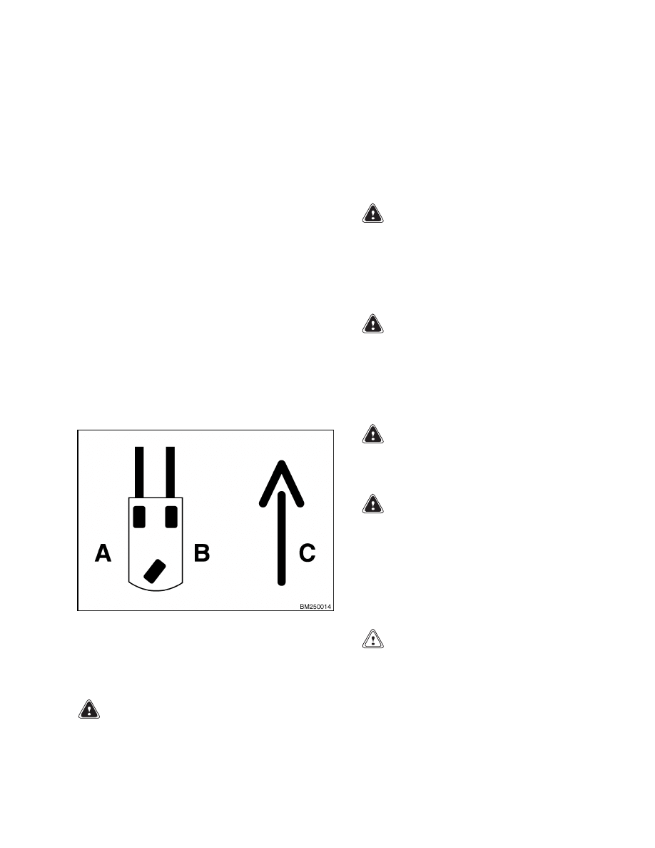
Throughout this section, forward will refer to travel
in the direction of the forks and left and right deter-
mined by an operator sitting in the seat facing for-
ward. See Figure 1.
A. LEFT SIDE
B. RIGHT SIDE
C. FORWARD
TRAVEL
Figure 1. Truck Orientation
DISCHARGING THE CAPACITORS
WARNING
Do not make repairs or adjustments unless you
have both authorization and training. Repairs
and adjustments that are not correct can cre-
ate dangerous operating conditions. Do not op-
erate a lift truck that needs repairs. Report
the need for repairs to your supervisor imme-
diately. If repair is necessary, attach a DO NOT
OPERATE tag to the steering wheel. Remove
the key from the key switch.
WARNING
Disconnect the battery before opening the
drive unit compartment cover or inspecting or
repairing the electrical system. If a tool causes
a short circuit, the high current flow from the
battery can cause personal injury or property
damage.
WARNING
Some checks and adjustments are done with
the battery connected.
Do not connect the
battery until the procedure tells you to do so.
Never have any metal on your fingers, arms,
or neck. Metal items can accidentally make an
electrical connection and cause injury.
WARNING
Before performing any tests or adjustments,
block the lift truck to prevent unexpected
movement.
WARNING
The capacitor in the transistor controller(s)
can hold an electrical charge after the battery
is disconnected. To prevent an electrical shock
and personal injury, discharge the capacitor(s)
before inspecting or repairing any component
in the drive unit compartment.
Wear safety
glasses.
Make certain that the battery has
been disconnected.
CAUTION
To avoid controller damage, always disconnect
the battery, discharge the capacitor(s), and
never put power to the controller while any
power wires are disconnected.
Never short
any controller terminal or motor terminal to
1
Introduction
1600 SRM 1075
the battery. Make sure to use proper proce-
dure when servicing the controller.
1.
Block load wheels to prevent lift truck from mov-
ing.
2.
Turn key switch to OFF position and disconnect
the battery.
WARNING
DO NOT short across the motor controller ter-
minals with a screwdriver or jumper wire.
NOTE:
Some lift trucks are equipped with a pre-
mium controller, which controls the hydraulic motor,
as well as the traction motors.
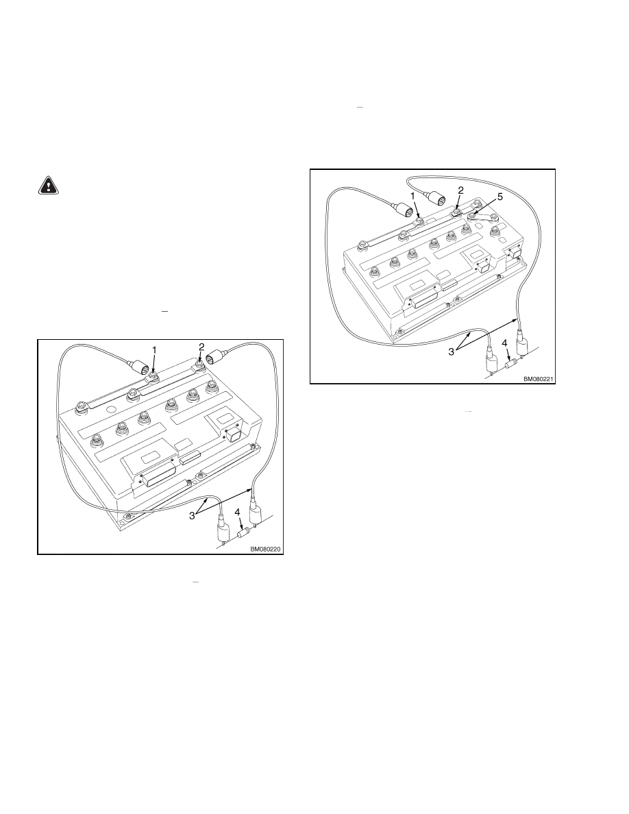
3.
Discharge the capacitor in the controller by con-
necting a 200-ohm, 2-watt resistor across the
controller’s BT+ and B
terminals for 10 seconds
using insulated jumper wires. See Figure 2.
1.
POSITIVE CONNECTION (BT+)
2.
NEGATIVE CONNECTION (B )
3.
INSULATED JUMPER WIRES
4.
200-OHM, 2-WATT RESISTOR
Figure 2. Discharging the Capacitors
(Standard)
4.
On the premium controller, also connect a 200-
ohm, 2-watt resistor across the controller’s P+
and B
terminals for 10 seconds using insulated
jumper wires. See Figure 3.
5.
Remove the 200-ohm, 2-watt resistor before re-
connecting the battery.
1.
POSITIVE CONNECTION (BT+)
2.
NEGATIVE CONNECTION (B )
3.
INSULATED JUMPER WIRES
4.
200-OHM, 2-WATT RESISTOR
5.
POSITIVE CONNECTION (P+)
Figure 3. Discharging the Capacitors
(Optional)
2

1600 SRM 1075
Steering Pressure Check
Description of Operation
Turning the steering wheel actuates three main
parts of the steering control unit:
• Spool for the control section
• Sleeve for the control section
• Rotor in the metering section
When the steering wheel is not moving, the spool
and sleeve are held in the neutral (center) position
by springs. During this time, oil flows freely through
the steering control unit. The oil does not flow to the
steering unit.
As the steering wheel is turned, the spool begins to
rotate. The springs try to move the sleeve to keep the
neutral position between the spool and sleeve. How-
ever, the force necessary to turn the rotor is greater
than the pressure of the springs. The springs bend,
letting the spool move a small amount within the
sleeve. The spool stops moving when it touches the
center pin. In this position, the holes in the sleeve
and the spool are aligned. Oil coming into the con-
trol unit flows to the metering section.
More rotation of the steering wheel causes the spool
to rotate the pin. This action causes the rotation of
the sleeve and the rotor in the metering section. The
oil then flows to one side of the steering unit. Hy-
draulic oil from the other side of the steering unit re-
turns through the control section of the steering con-
trol unit.
When the steering wheel stops moving, the metering
action in the metering section also stops. The neutral
position springs return the sleeve to the neutral po-
sition. When this action occurs, the pressure stays in
the steering cylinder to keep the steer wheels in po-
sition. Oil from the pump flows through the steering
control unit to the tank or other parts of the system.
To return the steering wheel to the straight position,
the steering wheel must be rotated in the opposite
direction. The steering control unit will operate as
described, but all parts will rotate in the opposite di-
rection.
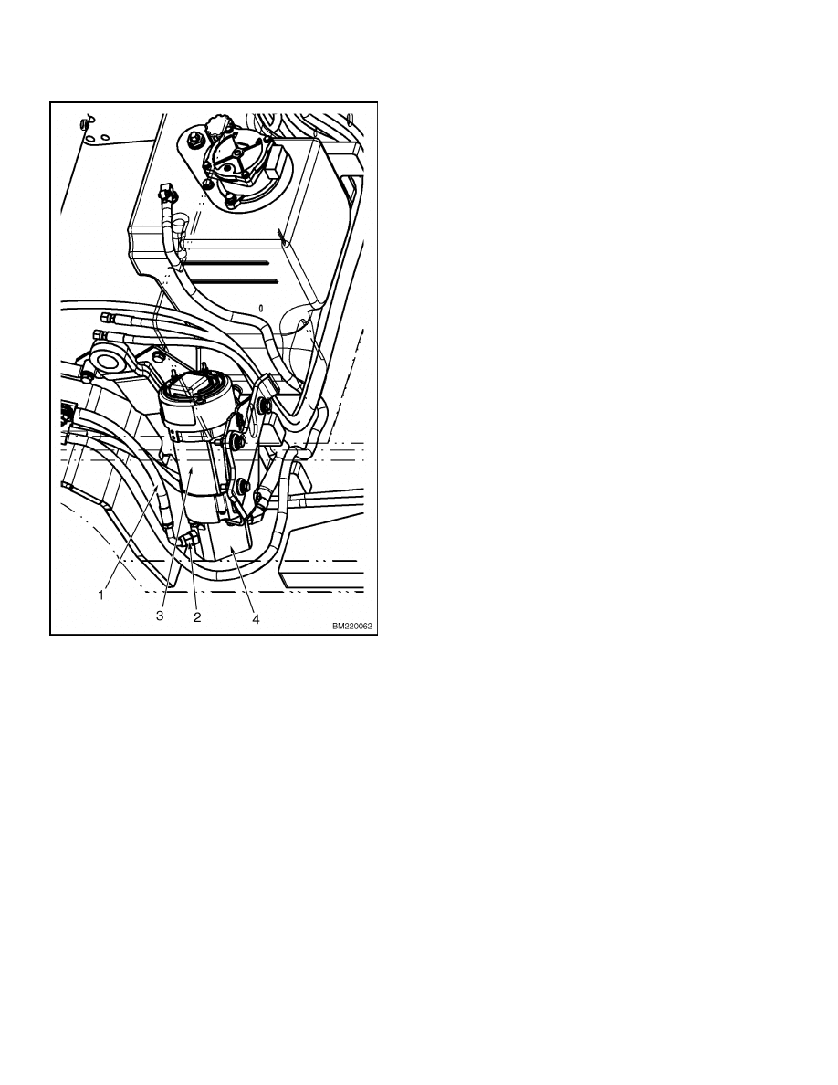
Steering Pressure Check
The steering system can be evaluated by checking the
system pressure. Using a hydraulic pressure gage,
tee into the steering pressure hose and check the sys-
tem pressures. See Figure 4.
For the following procedures, you will need a hy-
draulic pressure gage with a capacity of at least
100 bar (1450 psi) connected to a flared tee fitting
(male, number 6).
You will also need an exten-
sion hose [a hydraulic hose approximately 2 feet in
length with a 90 degree, flared swivel fitting (female,
number 6) on one end and a straight flared fitting
(female, number 6) for connecting to the tee fitting
on the other end].
NOTE:
The correct relief valve pressure is 75.8
±2.5 bar (1100 ±36 psi).
1.
Install a hydraulic pressure gauge between the
power steering pump and the steering control
unit. See Figure 4.
a. Turn the key switch to the OFF position and
disconnect the battery.
b. Remove floor mat and floor plates.
c.
Remove the steering pressure hose from the
pump pressure port fitting.
d. Install the 90 degree fitting end of the exten-
sion hose onto the pump pressure port fitting.
e.
Install the steering pressure hose and the ex-
tension hose to the tee fitting attached to the
hydraulic pressure gage.
2.
Connect the battery. Have a technician sit in the
seat and turn the key switch to the ON position.
3.
Have the technician operate the steering control
unit by rotating the steering wheel to its full left
or full right position. Check that maximum pres-
sure is 75.8 ±2.5 bar (1100 ±36 psi).
4.
If pressure is greater than 78.3 bar (1136 psi), re-
place steering control unit. See Steering Control
Unit Assembly.
3
Steering Pressure Check
1600 SRM 1075
1.
STEERING PRESSURE HOSE
2.
PUMP PRESSURE PORT FITTING
3.
STEERING PUMP MOTOR
4.
STEERING PUMP
Figure 4. Steering Pressure Check
5.
If pressure is less than 73.3 bar (1064 psi), the
steering pump may be at fault. Check the steer-
ing pump for proper hydraulic pressure:
a. Turn the key switch to the OFF position and
disconnect the battery.
b. Install a gate valve (open) between the steer-
ing pressure hose and the tee fitting.
c.
Connect the battery. Have a technician sit in
the seat and turn the key switch to the ON
position.
d. Have the technician operate the steering con-
trol unit by rotating the steering wheel to its
full left or full right position.
e.
SLOWLY close the gate valve to restrict the
flow of hydraulic oil until the pressure gage
rises to 73.3 bar (1064 psi) while the steering
wheel is in its full left or full right position.
f.
If the steering system pressure does not rise
above 73.3 bar (1064 psi), the pump is not
performing properly. Repair or replace the
steer pump. See Steering Control Unit As-
sembly.
6.
When pressure checks are complete:
a. Turn the key switch to the OFF position and
disconnect the battery.
b. Remove extension hose from pump pressure
port fitting.
c.
Remove steering pressure hose from tee. Re-
move gate valve if installed.
d. Install steering pressure hose to pump pres-
sure port fitting.
e.
Install floor plates and floor mat.
7.
Perform an operation check before returning to
service. See Operation Check.
4
1600 SRM 1075
Steering Wheel and Column
Operation Check
The purpose of this check is to make sure the steer-
ing trunnion turns the correct degrees of its rotation
(approximately 180 degrees). Put the lift truck on
blocks so the weight of the lift truck is removed from
the steering trunnion.
Operate the power steering system.
Rotate the
trunnion to its stop in one direction, then rotate the
trunnion to its stop in the other direction. Check
that the steering wheel turns the trunnion smoothly.
The face of the wheel should be approximately par-
allel to the frame plate at the back of the battery
compartment when the steering trunnion is rotated
fully in each direction to its stops.
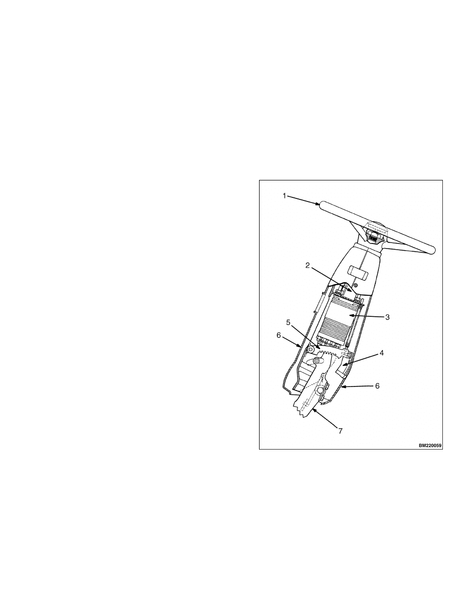
Steering Wheel and Column
This procedure is for the removal of all components
of the steering wheel and column assembly. See Fig-
ure 5. It may not be necessary to remove all compo-
nents for a repair procedure. Perform only the steps
necessary to complete the repair.
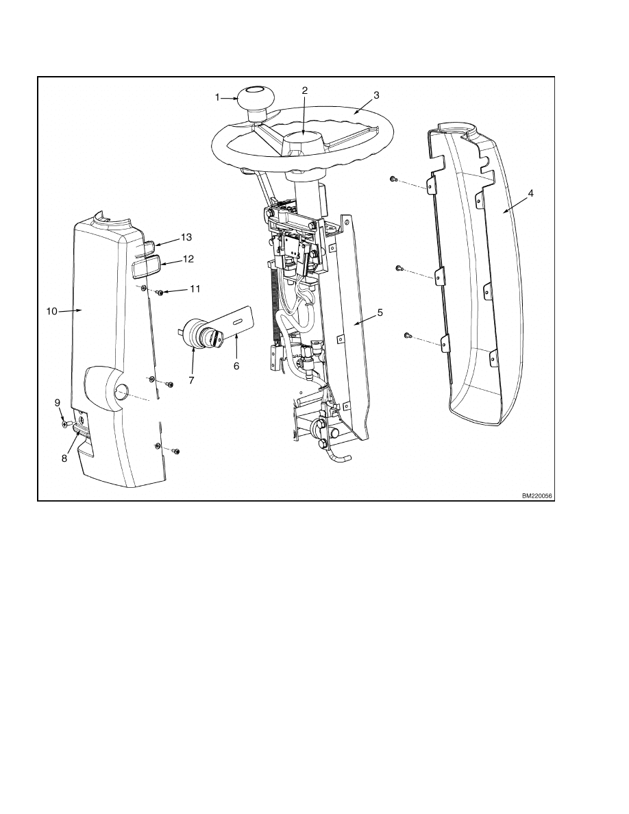
STEERING COLUMN COVERS
Remove
For the following procedures, refer to Figure 6.
1.
Turn the key switch to the OFF position. Discon-
nect the battery connector.
2.
Disassemble the covers by removing six screws
(11) securing covers together and two screws (9)
holding the latch release. Carefully separate the
covers. See Figure 6.
3.
Disconnect wiring harness from the key switch
and remove key switch from rear cover if neces-
sary.
Install
1.
Install key switch and static ground strap to
lower cover, if removed. Connect wiring harness
to key switch.
2.
Install the covers by assembling each half around
the steering column and installing six screws.
See Figure 6.
3.
Install latch release and secure using two screws
(9).
4.
Reconnect the battery connector and test for
proper operation.
1.
STEERING WHEEL
2.
STEERING SHAFT
3.
STEERING CONTROL UNIT
4.
LATCH RELEASE
5.
ADJUSTING LATCH MECHANISM
6.
COLUMN COVERS
7.
COLUMN BASE
Figure 5. Steering Wheel and Column
5
Steering Wheel and Column
1600 SRM 1075
1.
STEERING KNOB
2.
STEERING WHEEL CAP
3.
STEERING WHEEL
4.
UPPER COVER
5.
COLUMN BRACKET
6.
STATIC GROUND STRAP
7.
KEY SWITCH
8.
LATCH RELEASE
9.
SCREW
10. LOWER COVER
11. SCREW
12. PLUG
13. PLUG
Figure 6. Steering Column Covers
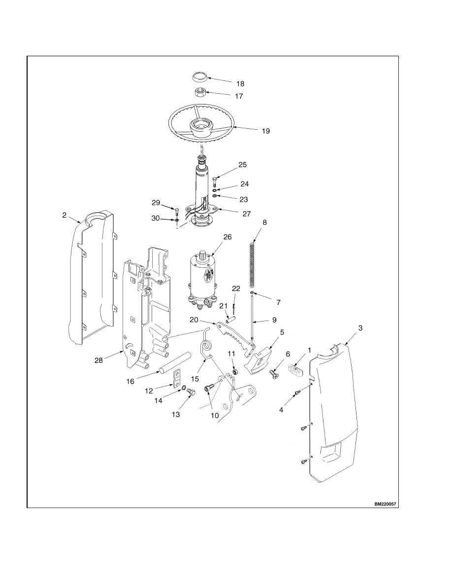
STEERING COLUMN COMPONENTS
Remove
See Figure 7 and Figure 8 for the following proce-
dures.
1.
Using a hammer and a punch, gently tap upward
around the edges of the steering wheel cap to re-
move from the steering wheel.
2.
Remove the steering lock nut and, using the heel
of your hand, bump upward on each side of the
steering wheel to remove.
3.
Tag and disconnect hoses from bottom of steering
control unit. Cap ports and plug hoses to mini-
mize leakage.
4.
Tag and disconnect wires and remove the horn
contacts and the encoder on the steering column.
6
1600 SRM 1075
Steering Wheel and Column
5.
Tag and disconnect wires and remove the direc-
tional switch plate and directional control lever
assembly if so equipped. See Figure 7.
6.
Remove the four capscrews (25), lockwashers
(24), and washers (23) securing steering shaft
and steering control unit assembly to column
bracket.
Remove assembly from steering col-
umn. See Figure 8.
NOTE:
Mark the steering control unit and the steer-
ing shaft for proper alignment during assembly.
7.
Separate steering shaft from steering control
unit by removing four capscrews (29) and lock-
washers (30) securing units together.
8.
Remove tilt limit capscrew (10) and lock nut (11).
WARNING
Tilt return spring is under tension. Be careful
when servicing tilt assembly components. Al-
ways wear eye protection.
9.
Remove steering column tilt adjustment linkage
if necessary.
a. Tilt the steering column to its upright posi-
tion.
b. Move the bracket spring to relieve tension
using a prybar.
c.
Compress and hold the tilt lock spring while
removing the spring guide shaft, tilt lock
spring, and cup washer.
d. Remove cotter pin and the lock pivot pin.
e.
Remove tilt lock bracket from steering col-
umn.
NOTE:
Support column bracket with a sling and
overhead lifting device or have an assistant hold the
bracket.
10. Release pivot shaft from retainer brackets by re-
moving capscrews (13) and washers (14) and re-
move column bracket from truck.
11. Remove pivot pin and bracket spring from col-
umn base.
1.
DIRECTIONAL CONTROL LEVER ASSEMBLY
2.
STEERING COLUMN
3.
DIRECTIONAL SWITCH PLATE
4.
ATTACHING HARDWARE
5.
ATTACHING HARDWARE
Figure 7. Directional Controls
7
Steering Wheel and Column
1600 SRM 1075
Figure 8. Steering Column
8

1600 SRM 1075
Steering Wheel and Column
Legend for Figure 8
1.
DIRECTIONAL LEVER GUIDE
2.
UPPER COVER
3.
LOWER COVER
4.
SCREW
5.
TILT LEVER
6.
TILT LEVER SCREWS
7.
CUP WASHER
8.
TILT LOCK SPRING
9.
SPRING GUIDE SHAFT
10. TILT LIMIT CAPSCREW
11. LOCK NUT
12. PIVOT PIN RETAINER
13. CAPSCREW
14. WASHER
15. BRACKET SPRING
16. PIVOT PIN
17. STEERING LOCK NUT
18. STEERING WHEEL CAP
19. STEERING WHEEL
20. TILT LOCK BRACKET
21. LOCK PIVOT PIN
22. COTTER PIN
23. WASHER
24. LOCKWASHER
25. CAPSCREW
26. STEERING CONTROL UNIT
27. STEERING SHAFT
28. COLUMN BRACKET
29. CAPSCREW
30. LOCKWASHER
Install
See Figure 8 for the following procedures.
1.
Install pivot pin (16) and bracket spring (15) to
column base. See Figure 8.
NOTE:
Support column bracket with a sling and
overhead lifting device or have an assistant hold the
bracket.
NOTE:
DO NOT set bracket spring tension at this
time.
2.
Secure pivot shaft to column bracket by in-
stalling pivot pin retainers (12) using capscrews
(13) and washers (14).
3.
Install steering column tilt adjustment linkage if
removed.
a. Position tilt lock bracket to column bracket
and install lock pivot pin (21) and cotter pin
(22).
b. Compress and hold the tilt lock spring while
installing the spring guide shaft, tilt lock
spring, and cup washer.
c.
Tilt the steering column to its upright posi-
tion.
d. Install tilt limit capscrew (10) and lock nut
(11).
4.
Set bracket spring tension at this time.
NOTE:
Align the steering control unit and the steer-
ing shaft as removed.
5.
Assemble steering shaft to steering control unit
using four capscrews (29) and lockwashers (30)
to secure together.
6.
Position steering shaft and steering control unit
assembly into steering column. Install four cap-
screws (25), lockwashers (24), and washers (23)
securing assembly to column bracket.
7.
Install directional control lever assembly and di-
rectional switch plate and wiring if so equipped.
See Figure 7.
8.
Remove caps and plugs from hoses and ports.
Connect hoses to bottom of steering control unit
as removed.
9.
Install steering wheel to steering shaft as re-
moved. Install the steering lock nut.
10. Install the horn contacts and the encoder on the
steering column. Connect wires as removed.
11. Install cap to the center of the steering wheel.
9
Power Steering Pump and Motor
1600 SRM 1075
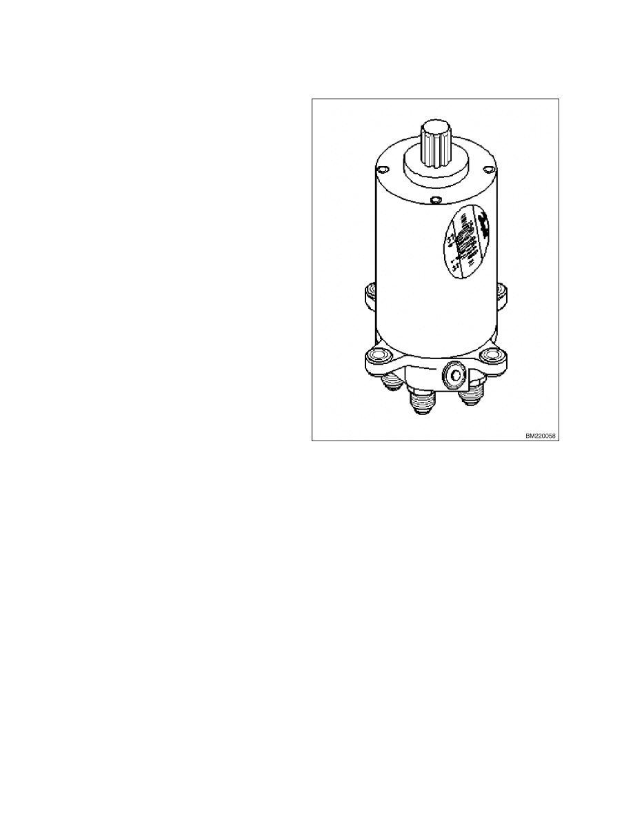
Steering Control Unit Assembly
The steering control unit is a metering device that
controls the flow of hydraulic oil to the steering ac-
tuator. See Figure 9. The steering pump and motor
sends pressurized hydraulic oil to the steering con-
trol unit where it is metered out to either side of the
steering actuator. The steering wheel is connected
to the steering control unit by the steering shaft and
controls the position of the steering control unit. The
unit is not serviceable and must be replaced if dam-
aged. Remove the unit from the steering column and
replace with a new unit if necessary. Refer to Steer-
ing Wheel and Column for removal and installation
procedures.
Figure 9. Steering Control Unit
Power Steering Pump and Motor
DESCRIPTION
The power steering pump and motor are located un-
der the floor plates on the left side of the truck. The
power steering pump is a single-section gear pump
that draws the hydraulic oil from the hydraulic
tank and directs the oil to the steering control unit
mounted in the steering column. The power steering
motor and pump operate when the key switch is ON
and the operator is on the seat (seat switch closed).
A timer stops the power steering motor 6 seconds
after the operator is off the seat (seat switch open)
and the key switch is still ON.
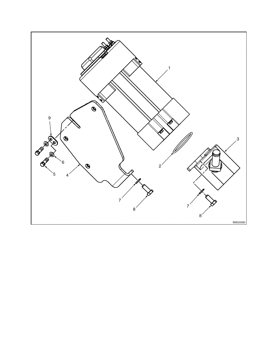
REMOVE
The power steering pump and motor must be re-
moved as a unit for servicing the pump. The power
steering pump and motor are mounted to the frame
with rubber isolator mounts. See Figure 10.
1.
Disconnect battery. Remove battery to gain ac-
cess to hex head bolts for mounting power steer-
ing pump and motor. Follow the instructions in
the section Periodic Maintenance 8000 SRM
1079 or the Operating Manual for battery re-
moval information.
2.
Remove floor mat and left side floor plate in the
operator compartment.
10
1600 SRM 1075
Power Steering Pump and Motor
1.
MOTOR
2.
O-RING
3.
PUMP
4.
MOUNTING PLATE
5.
CAPSCREW
6.
LOCKWASHER
7.
LOCKWASHER
8.
CAPSCREW
9.
SPACER
Figure 10. Pump and Motor Mount Figure
3.
Tag and disconnect electrical wires for identifica-
tion at assembly.
4.
Drain hydraulic tank.
See the section Hy-
draulic System 1900 SRM 1077.
5.
Disconnect suction line to power steering pump.
Disconnect discharge line from power steering
pump. Plug both hydraulic lines and pump ports
to prevent dirt from entering hydraulic system
and to prevent hydraulic oil from leaking from
system.
11
Power Steering Pump and Motor
1600 SRM 1075
WARNING
The power steering pump and motor are
heavy.
Be sure that all lifting devices (lifts,
cables, chains, slings, etc.) are suitable and of
adequate capacity to lift the power steering
pump and motor.
The power steering pump
and motor can weigh approximately 13.6 kg
(30 lb). The power steering motor has ceramic,
permanent magnets.
If the motor falls, the
magnets can be damaged.
6.
Remove three capscrews, washers, and bracket
retaining power steering pump and motor to lift
truck frame.
7.
Carefully lift power steering pump and motor out
of lift truck.
INSTALL
WARNING
The power steering pump and motor are
heavy.
Be sure that all lifting devices (lifts,
cables, chains, slings, etc.) are suitable and of
adequate capacity to lift the power steering
pump and motor.
The power steering pump
and motor can weigh approximately 13.6 kg
(30 lb). The power steering motor has ceramic
permanent magnets.
If the motor falls, the
magnets can be damaged.
1.
Carefully locate power steering pump and motor
in lift truck.
2.
Align power steering pump and motor and
brackets with mount holes in frame.
Install
capscrews, washers, and nuts to retain pump
and motor to lift truck frame. Tighten nuts to
25 N•m (18 lbf ft).
3.
Remove plugs from discharge port and dis-
charge line.
Install discharge line into pump
port.
Clean and inspect in-line strainer.
Re-
place in-line strainer if necessary. Install in-line
strainer in suction line. Install suction line on
suction side of pump.
4.
Refill hydraulic tank to the proper level.
5.
Install all disconnected electrical wires.
6.
Install floor plates.
7.
Install battery. Follow the instructions in the
section Periodic Maintenance 8000 SRM 1079
or the Operating Manual for battery installa-
tion information.
8.
Connect battery, turn key switch to the ON posi-
tion, and test for proper operation.
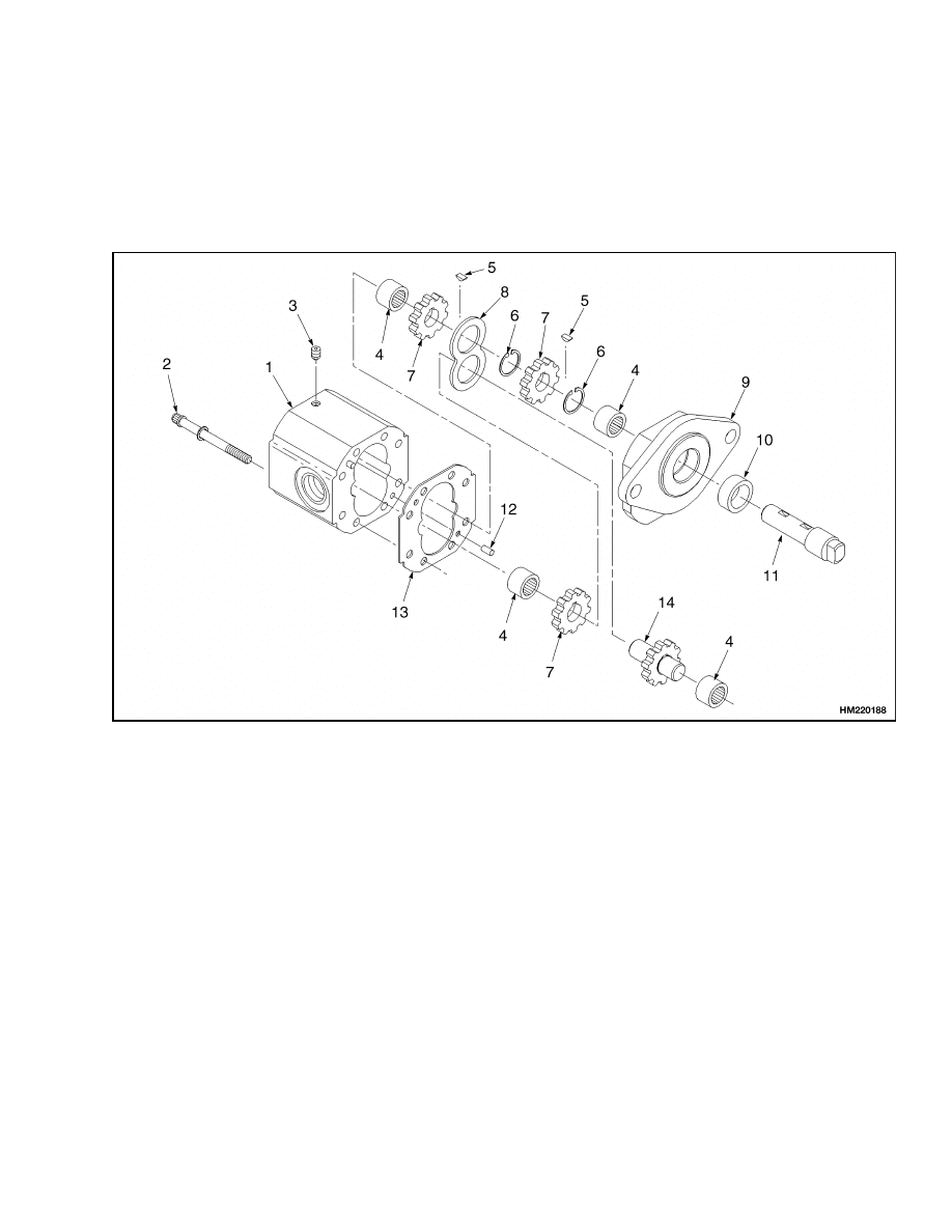
DISASSEMBLE
1.
Mark pump and motor to ensure proper align-
ment at assembly. Remove two capscrews and
washers retaining pump to motor.
Separate
pump from motor. See Figure 11.
2.
Remove eight capscrews and washers retaining
cover to housing. Carefully separate cover from
housing.
3.
Remove gears, drive shaft, keys, spacer, and idler
shaft and gear.
WARNING
Be careful when removing or installing snap
rings. These snap rings can come loose dur-
ing removal or installation with enough force
to cause an injury. Always use the correct snap
ring pliers and wear eye and face protection
during removal and installation.
4.
Remove snap rings and needle bearings.
5.
Clean and inspect needle bearings for damage.
Inspect gears, idler shaft and gear, and drive
shaft for erosion or damage. Replace all defec-
tive parts. Replace oil seal and joints.
ASSEMBLE
Lubricate all components with clean hydraulic oil be-
fore assembly.
WARNING
Be careful when removing or installing snap
rings. These snap rings can come loose dur-
ing removal or installation with enough force
to cause an injury. Always use the correct snap
ring pliers and wear eye and face protection
during removal and installation.
1.
Install needle bearings in pump halves. Install
snap rings to retain bearings.
12
1600 SRM 1075
Power Steering Pump and Motor
2.
Install spacer on shafts. Install remaining two
gears on shafts.
3.
Install oil seal in upper half of pump. Carefully
install drive shaft through oil seal and needle
bearing. Install keys on drive shaft.
4.
Install idler shaft and gear in needle bearing of
upper half of pump. Align and install gear on
drive shaft and key so it mates with idler gear.
5.
Ensure housing and cover are properly aligned
and install gasket. Install eight capscrews and
washers retaining housing and cover together.
1.
HOUSING
2.
SCREW
3.
PLUG
4.
NEEDLE BEARING
5.
KEY
6.
SNAP RING
7.
GEAR
8.
SPACER
9.
COVER
10. OIL SEAL
11. DRIVE SHAFT
12. GUIDE PIN
13. GASKET
14. IDLER SHAFT AND GEAR
Figure 11. Power Steering Pump
13
Steering Actuator Components
1600 SRM 1075
Steering Actuator Components
The steering actuator assembly has a horizon-
tal shaft and gear assembly (pinion) that extends
through the gear housing, which is mounted in the
bottom of the counterweight. The pinion is rotated
by the horizontal movement of a hydraulic-driven
gear rack. The power steering pump feeds hydraulic
oil to the steering control unit, which directs the oil
into either end of the gear housing. The housing acts
as a cylinder tube. Pistons, at each end, control the
movement of the gear rack.
STEER TIRE AND WHEEL ASSEMBLY
Remove
WARNING
Before attempting to remove the steer tire
and wheel assemblies from the steering axle,
put blocks under each side of the frame. The
blocks must prevent the lift truck from falling
and causing injury or damage. Do not place
jacking equipment under the counterweight.
NOTE:
Perform the following procedures for each
steer tire and wheel assembly.
1.
Turn steering wheel so steer tire and wheel as-
sembly to be removed is accessible. Turn key
switch to the OFF position and disconnect the
battery.
2.
Block the drive wheels to prevent unexpected
movement and apply parking brakes.
WARNING
Do not place jacking equipment under the
counterweight.
3.
Place the rear of the lift truck frame on blocks to
suspend the steer tires off the ground. See How
to Put Lift Truck on Blocks in either the Oper-
ating Manual or the section Periodic Mainte-
nance 8000 SRM 1079.
4.
Loosen lug nuts retaining steer tire and wheel
assembly.
5.
Remove lug nuts and wheel assembly from steer-
ing axle.
Install
WARNING
Lifting and carrying of tires is not recom-
mended because their weight could be in
excess of 45 kg (100 lb). Where applicable, use
a wheel or tire dolly to assist in the removal
and installation of the wheel. Follow the in-
structions in the section Periodic Maintenance
8000 SRM 1079 or the Operating Manual.
1.
Align wheel and tire assembly with studs and
install wheel and tire assembly on wheel hub.
2.
Install lug nuts on studs to retain wheel assem-
bly. Tighten nuts snugly.
3.
Lower lift truck to floor.
Tighten lug nuts to
170 N•m (125 lbf ft).
4.
Remove blocks from wheels. Connect the battery.
5.
After 2 to 5 hours of operation, check all wheel
nuts.
Tighten lug nuts in a cross pattern to
170 N•m (125 lbf ft). When nuts stay tight after
an 8-hour check, the interval for checking the
torque can be extended to 350 hours.
WHEEL HUB ASSEMBLY
Remove
NOTE:
The instructions are for one wheel hub assem-
bly. If necessary, perform the same operation for the
opposite side.
1.
Remove wheel and tire assembly. See Steer Tire
and Wheel Assembly, Remove.
2.
Remove hub cap. Straighten, remove, and dis-
card cotter pin. Remove nut, washer, spacer, and
hub assembly.
WARNING
Be careful when removing or installing snap
rings. These snap rings can come loose dur-
ing removal or installation with enough force
to cause an injury. Always use the correct snap
ring pliers and wear eye and face protection
during removal and installation.
3.
Remove and discard nilos sealing rings from hub.
Use a soft, metal drift to remove bearings.
14
1600 SRM 1075
Steering Actuator Components
4.
Inspect bearings for damage. Inspect axle shaft
for damage or corrosion. Inspect wheel studs for
damage. Replace all damaged components.
Install
1.
Prior to installation, pack bearings and new nilos
sealing rings with grease. See the section Peri-
odic Maintenance 8000 SRM 1079 or the Op-
erating Manual for the recommended grease.
WARNING
Be careful when removing or installing snap
rings. These snap rings can come loose dur-
ing removal or installation with enough force
to cause an injury. Always use the correct snap
ring pliers and wear eye and face protection
during removal and installation.
2.
Install snap rings in hub to retain bearings.
Make certain snap rings are seated in wheel
hub. Install both inner and outer wheel bearings
in hub. Install inner nilos sealing ring.
3.
Carefully install hub on axle so seal is not dam-
aged. Install outer nilos sealing ring.
4.
Install spacer and washer on axle. Install slotted
nut. Tighten nut to 47 N•m (35 lbf ft). Rotate
wheel while tightening nut. If necessary, back
off on the nut to align nut and hole in axle shaft.
5.
Install new cotter pin. Install hub cap.
6.
Install wheel assembly. See Steer Tire and Wheel
Assembly, Remove.
STEERING AXLE ASSEMBLY
Remove
NOTE:
The removal instructions listed are performed
with the counterweight, wheels, and tires installed.
1.
Disconnect battery connector. Block drive tires.
Position blocks between steer tires and steering
axle weldment to prevent tires and wheels from
rotating. Remove wheel assembly.
2.
Remove two capscrews that retain rear cover to
counterweight. Remove rear cover.
WARNING
The capacitors in the traction controllers can
hold an electrical charge after the battery is
disconnected. To prevent electrical shock and
injury, discharge the capacitors after discon-
necting the battery connector and before re-
pairing or replacing any component in the rear
compartment. Wear safety glasses. Make cer-
tain the battery has been disconnected. Dis-
charge the capacitors in the controllers by con-
necting a 200-ohm, 2-watt resistor across the
controller’s POS and NEG terminals (outer two
power cable terminals). DO NOT short across
the motor controller terminals with a screw-
driver or jumper wire. Remove the 200-ohm,
2-watt resistor before reconnecting the battery.
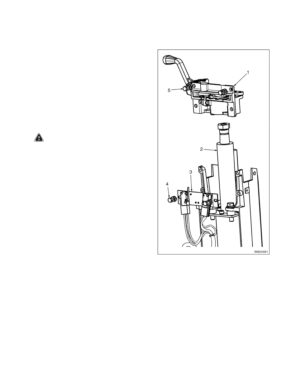
3.
Discharge controller capacitors.
4.
Unscrew cylinder from gear housing. Remove
O-ring from gear housing. See Figure 12.
5.
Remove piston from inside cylinder.
6.
Remove two piston guideways and compact seal
from piston.
7.
Remove four capscrews that fasten yoke assem-
bly and gear housing shaft assembly. Separate
shaft assembly from yoke assembly.
8.
Remove cap from end of wheel hub. Remove cot-
ter pin, nut, and u-disc.
9.
Remove assembled wheel hub from yoke shaft.
Remove bearings and wheel bolts if necessary.
10. Remove nilos ring from yoke shaft.
11. Remove nut, washer, shims, nilos ring, and bear-
ings from flange shaft.
15
Steering Actuator Components
1600 SRM 1075
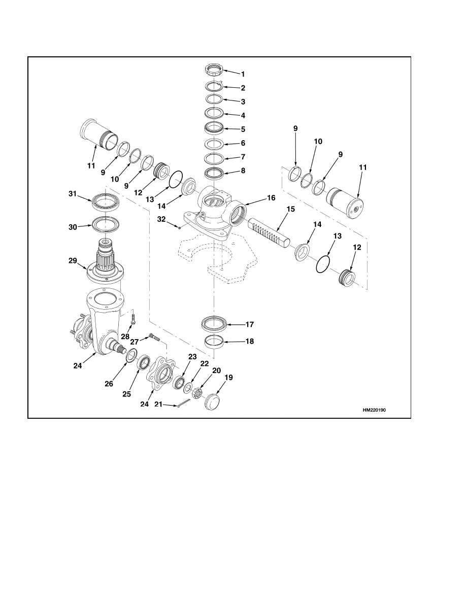
1.
NUT
2.
WASHER
3.
SHIM
4.
NILOS RING
5.
BEARING
6.
SHIM
7.
SAFETY RING
8.
SHAFT SEAL
9.
PISTON GUIDEWAY
10. COMPACT SEAL
11. CYLINDER
12. PISTON
13. O-RING
14. LINER
15. GEAR RACK
16. HOUSING
17. SHAFT SEAL
18. RACEWAY
19. CAP
20. NUT
21. COTTER PIN
22. U-DISC
23. BEARING
24. WHEEL HUB
25. BEARING
26. NILOS RING
27. WHEEL BOLT
28. CAPSCREW
29. FLANGE SHAFT
30. NILOS RING
31. BEARING
32. PLUG SCREW
Figure 12. Steering Axle Assembly
16

1600 SRM 1075
Steering Actuator Components
12. Remove flange shaft from gear housing.
13. Remove bearing and nilos ring from flange shaft.
14. Slide gear rack out of gear housing. Remove lin-
ers from each end of gear housing.
15. Remove safety ring, shaft seals, and bearing
raceway from top and bottom opening of gear
housing if necessary.
Clean
WARNING
Cleaning solvents can be flammable and toxic
and can cause skin irritation.
When using
cleaning solvents, always follow the solvent
manufacturer’s recommended safety precau-
tions and procedures.
1.
Clean all parts in solvent.
2.
Dry parts with compressed air. Do not dry parts
with a cloth.
3.
Make sure all surfaces are free of scratches and
sharp edges.
Install
WARNING
After installation, test for proper operation.
STAY CLEAR OF THE STEERING WHEEL
WHEN INITIALLY ENERGIZING THE STEER-
ING SYSTEM AFTER ASSEMBLY. If the control
unit and/or the hoses were not assembled cor-
rectly, the steering wheel can rotate with a
strong force. If this action occurs, disassem-
ble the control unit and correct the existing
problem.
NOTE:
Use new seals and O-rings during assembly.
Lubricate all parts with clean hydraulic oil.
1.
Install shaft seal and bearing raceway into bot-
tom of gear housing. See Figure 12.
2.
Install safety ring in groove at top of gear hous-
ing. Install shaft seal into top of gear housing.
3.
Install liners into each end of gear housing. In-
stall gear rack through both liners in gear hous-
ing, making sure middle groove of gear rack is
located in middle of gear housing.
4.
Fill nilos ring with grease and position ring over
flange shaft. Press bearing on flange shaft.
5.
Install flange shaft through gear housing. In-
stall selected shims, bearing, nilos ring, addi-
tional shims, washer, and nut over end of flange
shaft.
6.
Install five wheel bolts into each wheel hub.
Press bearings into each end of wheel hubs. Fill
nilos ring with grease and place it over yoke
shaft. Install assembled wheel hub over yoke
shaft. Fill inside area of wheel hub with grease.
7.
Install u-disc and nut over end of yoke shaft.
Tighten nut firmly and secure assembly in place
with cotter pin. Install cap over end of wheel hub.
8.
Assemble yoke assembly to gear housing with
shaft assembly. A pressed pin in yoke will help
to properly align the two assemblies. Fasten the
two assemblies together with four capscrews.
9.
Install two piston guideways and a compact seal
over piston. Install piston into cylinder and push
piston to end of cylinder.
10. Apply a thin layer of #2 multipurpose grease with
2 to 4% molybdenum disulfide to the inside of the
cylinder.
11. Apply a light film of hydraulic oil on cylinder and
O-ring. Install O-ring into gear housing on top of
liners. Screw cylinder into end of gear housing.
12. Operate unit several times. Install plug screw
into gear housing.
13. Connect battery connector. Remove blocks from
between tires and steer axle.
14. Install rear compartment cover. Lower lift truck
to floor and remove blocks from drive wheels.
Test operate lift truck before returning lift truck
to service.
17

Troubleshooting
1600 SRM 1075
Troubleshooting
PROBLEM
POSSIBLE CAUSE
PROCEDURE OR ACTION
The axle does not turn when
the steering wheel is turned.
The steering pump fuse is open.
Check the steering pump fuse and re-
place if open.
The hydraulic oil level is low or there
is no oil in the tank.
Check for leaks. Fill the hydraulic oil
to the correct level.
No oil flow from the steering control
unit to the rotary actuator.
Remove, clean, and install the steer-
ing control unit, hoses, and rotary ac-
tuator.
The sleeve and spool in the steering
control unit will not move.
Clean or repair steering control unit.
Hydraulic hoses damaged or connec-
tions are open.
Check for leaks. Tighten hose con-
nections; if leaks continue, replace
hoses.
The steering control unit may be
damaged.
Repair or replace steering control
unit.
The electric motor for the steering
pump needs repair.
Repair or replace electric steering
motor.
Air in the steering hydraulic system.
Exercise the system until all air is
removed by the system.
Steering pump does not send oil to
the steering system.
Inspect the fuse; replace if open.
Suction
inlet
strainer
may
be
clogged.
Clean strainer.
The axle rotates in the wrong
direction from the direction
of the steering wheel.
The hydraulic hoses are connected
incorrectly at the rotary actuator.
Reconnect hydraulic hoses correctly.
The hydraulic hoses are connected
incorrectly at the steering control
unit.
Reconnect hydraulic hoses correctly.
If the steering control unit was disas-
sembled, check the rotor for correct
alignment.
Disassemble steering control unit
and align rotor correctly.
18

1600 SRM 1075
Troubleshooting
PROBLEM
POSSIBLE CAUSE
PROCEDURE OR ACTION
The axle continues to turn
after the steering wheel has
stopped turning.
A centering spring is broken in the
steering control unit.
Repair or replace steering control
unit.
There is damage to the sleeve or the
spool of the steering control unit.
Repair or replace steering control
unit.
Check for dirt in the hydraulic sys-
tem and the steering control unit.
Drain hydraulic oil completely and
replace with new hydraulic oil and a
new hydraulic oil filter.
The power steering pump
makes noise that is not nor-
mal.
There is air entering the power steer-
ing pump.
Check for air entering the pump
through the inlet port or the seals
between the pump and the motor.
The bearings in the electric motor
or the power steering pump need
repair.
Replace bearings in steering pump
motor.
Dirty inlet strainer.
Clean
inlet
strainer
using
an
oil-based solvent.
Slow or difficult steering.
The hydraulic oil level is low, or there
is no oil in the tank.
Refill hydraulic oil in tank.
No oil flow from the steering control
unit to the rotary actuator.
Remove, clean, and install the steer-
ing control unit, hoses, and rotary ac-
tuator.
Steering gearbox seals leaking.
Replace seals.
The sleeve and spool in the steering
control unit are binding.
Clean or replace steering control
unit.
Low hydraulic oil pressure.
Check pump for correct operation.
The steering control unit damaged.
Repair or replace the steering control
unit.
On-demand module defective.
Replace module.
19

NOTES
____________________________________________________________
____________________________________________________________
____________________________________________________________
____________________________________________________________
____________________________________________________________
____________________________________________________________
____________________________________________________________
____________________________________________________________
____________________________________________________________
____________________________________________________________
____________________________________________________________
____________________________________________________________
____________________________________________________________
____________________________________________________________
____________________________________________________________
____________________________________________________________
____________________________________________________________
____________________________________________________________
____________________________________________________________
____________________________________________________________
20


TECHNICAL PUBLICATIONS
1600 SRM 1075
3/04 Printed in United Kingdom
Document Outline
- toc
Wyszukiwarka
Podobne podstrony:
1554629 1800SRM1076 (03 2004) UK EN
1554631 2000SRM1085 (03 2004) UK EN
897953 1600SRM0639 (03 2005) UK EN
897986 1600SRM0658 (03 1997) UK EN
910460 1600SRM0258 (05 2004) UK EN
1453608 1600SRM0687 (03 2002) UK EN
1564053 0600SRM1101 (03 2004) UK EN
897983 1600SRM0655 (03 2002) UK EN
1482617 1600SRM0797 (03 2000) UK EN
1554626 0100SRM1073 (06 2004) UK EN
1482620 1600SRM0796 (03 2000) UK EN(1)
897881 1600SRM0619 (06 2004) UK EN
897545 1600SRM0532 (10 2004) UK EN
1554631 2000SRM1085 (03 2004) UK EN
897953 1600SRM0639 (03 2005) UK EN
więcej podobnych podstron