HYDRAULIC SYSTEM
J1.6-2.0XMT (J30-40ZT) [J160]
PART NO. 1554630
1900 SRM 1077

SAFETY PRECAUTIONS
MAINTENANCE AND REPAIR
• When lifting parts or assemblies, make sure all slings, chains, or cables are correctly
fastened, and that the load being lifted is balanced. Make sure the crane, cables, and
chains have the capacity to support the weight of the load.
• Do not lift heavy parts by hand, use a lifting mechanism.
• Wear safety glasses.
• DISCONNECT THE BATTERY CONNECTOR before doing any maintenance or repair
on electric lift trucks. Disconnect the battery ground cable on internal combustion lift
trucks.
• Always use correct blocks to prevent the unit from rolling or falling. See HOW TO PUT
THE LIFT TRUCK ON BLOCKS in the Operating Manual or the Periodic Mainte-
nance section.
• Keep the unit clean and the working area clean and orderly.
• Use the correct tools for the job.
• Keep the tools clean and in good condition.
• Always use HYSTER APPROVED parts when making repairs. Replacement parts
must meet or exceed the specifications of the original equipment manufacturer.
• Make sure all nuts, bolts, snap rings, and other fastening devices are removed before
using force to remove parts.
• Always fasten a DO NOT OPERATE tag to the controls of the unit when making repairs,
or if the unit needs repairs.
• Be sure to follow the WARNING and CAUTION notes in the instructions.
• Gasoline, Liquid Petroleum Gas (LPG), Compressed Natural Gas (CNG), and Diesel fuel
are flammable. Be sure to follow the necessary safety precautions when handling these
fuels and when working on these fuel systems.
• Batteries generate flammable gas when they are being charged. Keep fire and sparks
away from the area. Make sure the area is well ventilated.
NOTE: The following symbols and words indicate safety information in this
manual:
WARNING
Indicates a condition that can cause immediate death or injury!
CAUTION
Indicates a condition that can cause property damage!

Hydraulic System
Table of Contents
TABLE OF CONTENTS
Introduction........................................................................................................................................................
General ...........................................................................................................................................................
Discharging the Capacitors...........................................................................................................................
Hydraulic System...............................................................................................................................................
Hydraulic Oil .................................................................................................................................................
Hydraulic Lines .............................................................................................................................................
Cleaning .........................................................................................................................................................
Sound Level....................................................................................................................................................
Maintenance ..................................................................................................................................................
Hydraulic Oil Filter, Change ....................................................................................................................
Hydraulic Oil Strainer, Check ..................................................................................................................
Hydraulic Oil, Change ..............................................................................................................................
Hydraulic Tank Assembly .................................................................................................................................
Remove ...........................................................................................................................................................
Clean ..............................................................................................................................................................
Trisodium Phosphate Method...................................................................................................................
Install .............................................................................................................................................................
Lift Pump and Motor .........................................................................................................................................
Remove ...........................................................................................................................................................
Disassemble ...................................................................................................................................................
Assemble ........................................................................................................................................................
Install .............................................................................................................................................................
Lift Pump............................................................................................................................................................
Disassemble ...................................................................................................................................................
Assemble ........................................................................................................................................................
This section is for the following models:
J1.6-2.0XMT (J30-40ZT) [J160]
©2004 HYSTER COMPANY
i

"THE
QUALITY
KEEPERS"
HYSTER
APPROVED
PARTS
1900 SRM 1077
Introduction
Introduction
GENERAL
This section contains the description and repair pro-
cedures for the hydraulic system. Components cov-
ered include the hydraulic tank, lift pump, filter as-
sembly, and hoses. Some parts associated with the
hydraulic system are not covered in this section be-
cause they are more closely associated with other sys-
tems. See the following list for information not in-
cluded in this section.
• See the section Electrical System 2200 SRM
1078 for information on the lift truck electrical
systems.
• See the section Steering System 1600 SRM 1075
for information on steering system components and
functions.
• See the section AC Motor Controllers/Display
Panel, Description, Checks, Adjustments,
and Troubleshooting 2200 SRM 1087 for infor-
mation on power delivery to the traction motor
(and lift pump motor on transistor hydraulic mod-
els).
• See the section Electro-Hydraulic Control
Valve 2000 SRM 1086 for information on the elec-
tro-hydraulic control valve, valve controller, and
hydraulic control switches.
• See the section HUSCO™ Main Control Valve
2000 SRM 1085 for information on the manually
controlled hydraulic valve.
• See the section Periodic Maintenance 8000 SRM
1079 for information on regularly scheduled main-
tenance procedures.
• See the section Mast, Repairs 4000 SRM 522 for
information on lift cylinders and mast systems.
• See the section Capacities and Specifications
8000 SRM 1080 for proper torque values, fluid
capacities, pressure settings, and other specifica-
tions.
• See the section Tilt Cylinders 2100 SRM 103 for
information on tilt cylinders and tilt hydraulic sys-
tems.
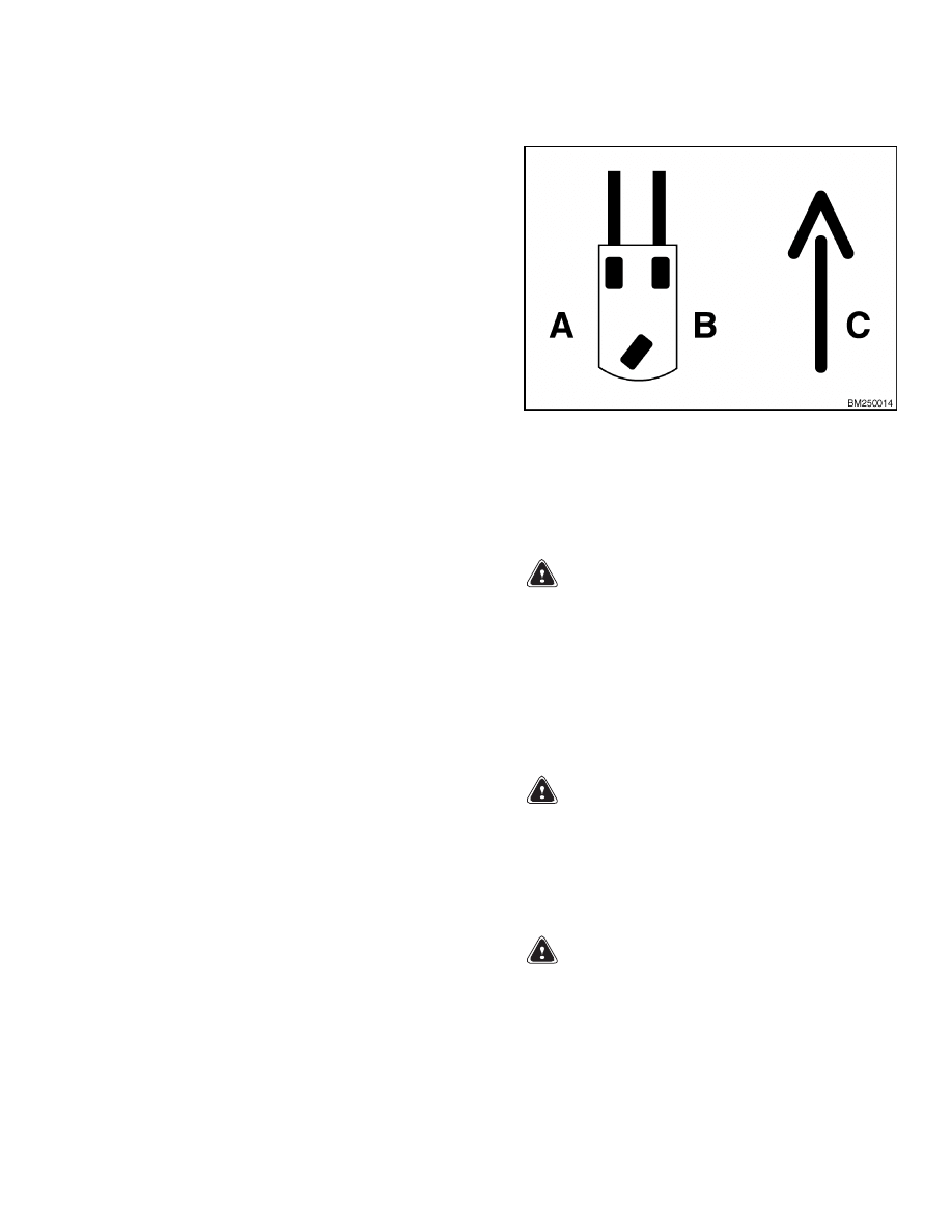
Throughout this section, forward will refer to travel
in the direction of the forks and left and right deter-
mined by an operator sitting in the seat facing for-
ward. See Figure 1.
A. LEFT SIDE
B. RIGHT SIDE
C. FORWARD TRAVEL
Figure 1. Truck Orientation
DISCHARGING THE CAPACITORS
WARNING
Do not make repairs or adjustments unless you
are properly trained and have been authorized
to do so. Repairs and adjustments that are not
correct can create dangerous operating condi-
tions. Do not operate a lift truck that needs re-
pairs. Report the need for repairs to your su-
pervisor immediately. If repair is necessary, at-
tach a DO NOT OPERATE tag to the steering
wheel and remove the key from the key switch.
WARNING
Disconnect the battery before opening the elec-
trical compartment cover and/or inspecting or
repairing the electrical system. If a tool causes
a short circuit, the high current flow from the
battery can cause personal injury or property
damage.
WARNING
Some checks and adjustments are performed
with the battery connected.
Do not connect
the battery until the procedure tells you to do
so. Never have any metallic objects, such as
jewelry, on your fingers, arms, or neck. Metal
items can accidentally make an electrical con-
nection and cause injury.
1
Introduction
1900 SRM 1077
WARNING
Block the lift truck tires to prevent unexpected
movement before performing any tests or ad-
justments.
WARNING
The capacitor(s) in the transistor controller
can hold an electrical charge after the battery
is disconnected. To prevent an electrical shock
and personal injury, discharge the capacitor(s)
before inspecting or repairing any component
in the electrical compartment.
Wear safety
glasses.
Make certain that the battery has
been disconnected.
CAUTION
To avoid controller damage, always disconnect
the battery, discharge the capacitor(s), and
never apply power to the controller while any
power wires are disconnected.
Never short
any controller terminal or motor terminal to
the battery. Make sure to follow proper proce-
dure when servicing the controller.
1.
Turn key switch to OFF position and disconnect
the battery.
2.
Block load wheels to prevent lift truck from mov-
ing.
WARNING
DO NOT short across the motor controller ter-
minals with a screwdriver or jumper wire.
NOTE: Some lift trucks are equipped with a pre-
mium controller, which controls the hydraulic motor,
as well as the traction motors.
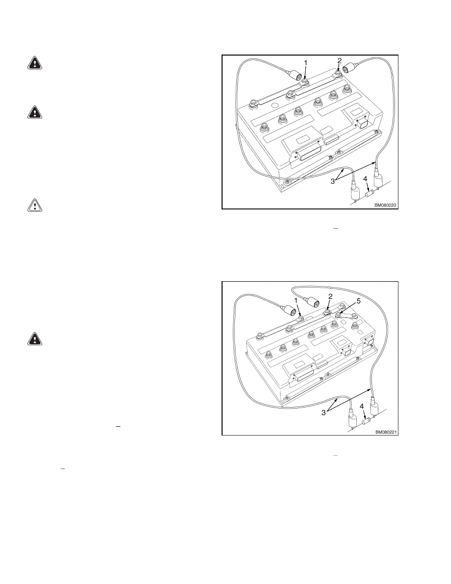
3.
Discharge the capacitor in the controller by con-
necting a 200-ohm, 2-watt resistor across the
controller’s BT+ and B
terminals for 10 seconds
using insulated jumper wires. See Figure 2.
4.
On the premium controller, also connect the 200-
ohm, 2-watt resistor across the controller’s P+
and B
terminals for 10 seconds using insulated
jumper wires. See Figure 3.
5.
Remove the 200-ohm, 2-watt resistor before re-
connecting the battery.
1.
POSITIVE CONNECTION (BT+)
2.
NEGATIVE CONNECTION (B )
3.
INSULATED JUMPER WIRES
4.
200-OHM, 2-WATT RESISTOR
Figure 2. Discharging the Capacitors
(Standard)
1.
POSITIVE CONNECTION (BT+)
2.
NEGATIVE CONNECTION (B )
3.
INSULATED JUMPER WIRES
4.
200-OHM, 2-WATT RESISTOR
5.
POSITIVE CONNECTION (P+)
Figure 3. Discharging the Capacitors
(Premium)
2

1900 SRM 1077
Hydraulic System
Hydraulic System
HYDRAULIC OIL
The hydraulic oil in the system performs the dual
function of power transmission and lubrication. Us-
ing the proper oil is essential to system operation.
See the section Capacities and Specifications
8000 SRM 1080 for the recommended hydraulic oil
specifications and quantities.
The hydraulic oil level should be checked first when
troubleshooting hydraulic system problems. Low oil
levels may cause it to appear that a problem exists
with the battery or hydraulic components.
HYDRAULIC LINES
All hydraulic hoses and tubes must be thoroughly
cleaned before installation.
When making repairs, use the least number of fit-
tings and connections to minimize flow resistance
and the possibility of leakage.
CLEANING
Take precautionary measures to ensure that the hy-
draulic system remains clean.
1.
Clean the reservoir and pump area before servic-
ing to prevent contaminants from entering the
hydraulic system.
2.
Clean (flush) the entire system when a failure is
encountered to make sure all paint, metal chips,
welding shot, and debris are removed.
3.
Filter each change of oil to prevent the introduc-
tion of contaminants into the system.
4.
Provide continuous protection from airborne con-
tamination by keeping the breather cap clean
and serviceable.
SOUND LEVEL
Hydraulic system noise may be caused by both im-
properly selected oil and loose or damaged system
components.
• Cavitation - Can be caused by high fluid viscosity,
cold fluid temperatures, or a restriction in the in-
let screen or inlet tubing. At startup, low temper-
atures can cause pump noises due to cavitation.
• Aerated hydraulic oil - Results in system noise that
is similar to cavitation. Aerated oil is caused by
the ingestion of air through the joints of the in-
let lines and high-velocity discharge lines. Aera-
tion can also be caused by oil discharging above the
fluid level in the hydraulic reservoir. Aerated hy-
draulic oil occurs when air does not have sufficient
time to escape from the fluid while in the reservoir
before recycling through the system.
MAINTENANCE
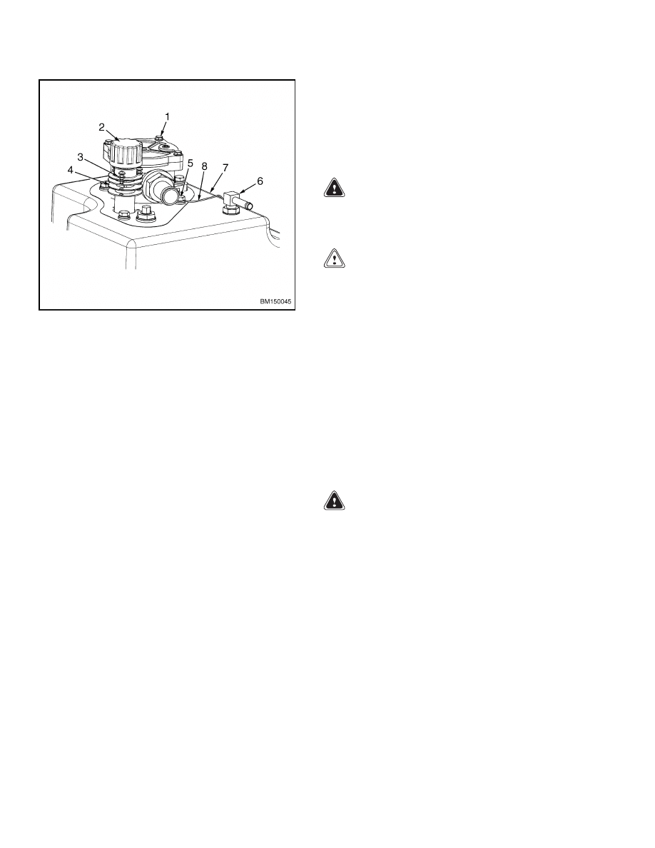
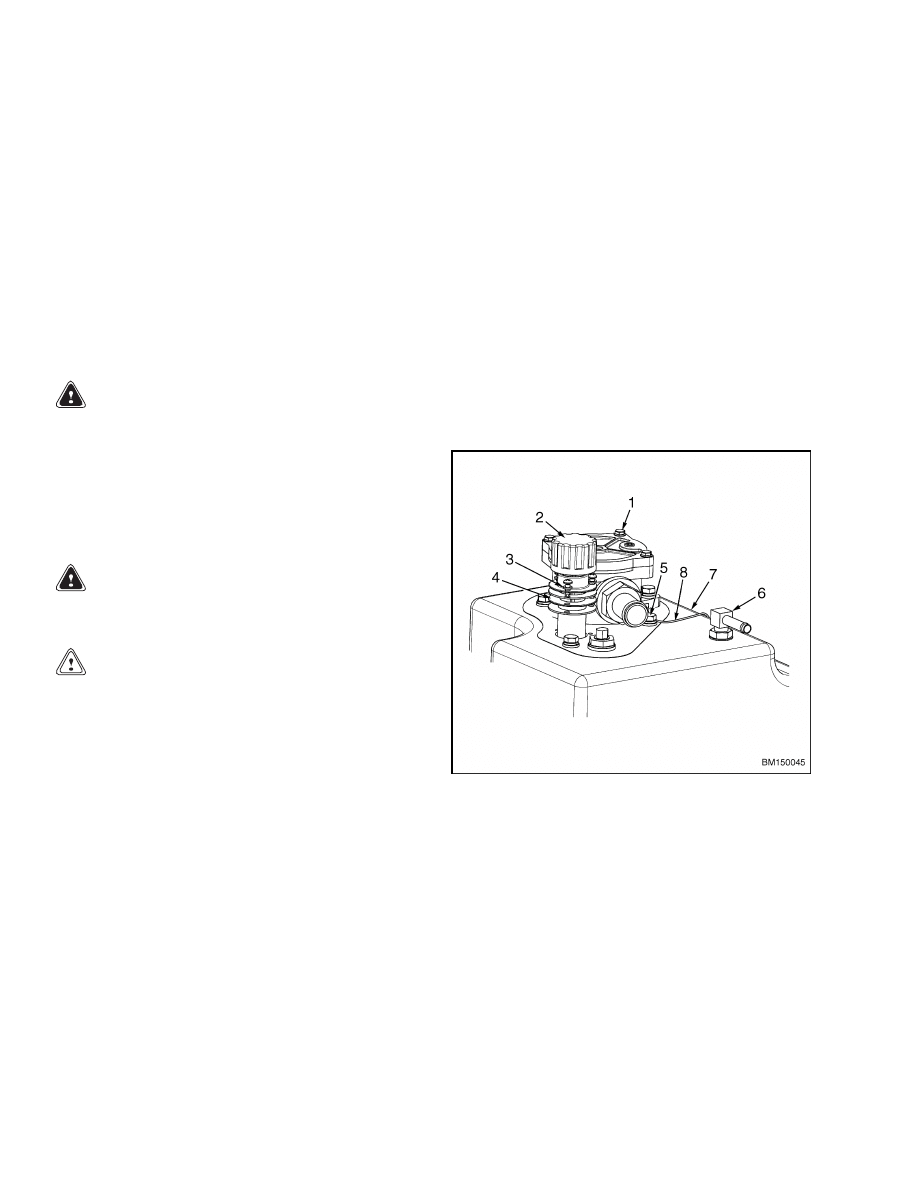
Hydraulic Oil Filter, Change
Replace the filter element after the first 50 hours of
service and every 2000 hours or yearly thereafter.
See Figure 4.
1.
Loosen the four capscrews (1) securing cover to
the hydraulic oil filter housing located on top of
the hydraulic oil tank.
2.
Press down on the cover while removing the cap-
screws to depress the element retainer spring.
3.
Remove the cover and spring from housing.
Check O-ring seal on the cover for cracks or
deterioration. Replace if damaged.
4.
Remove element from housing and replace with
a new element.
5.
Install the cover and spring to the housing using
four capscrews. Press the cover down onto the
housing while installing the capscrews. Torque
capscrews to 6 N•m (53 lbf in).
6.
Clean the breather cap/dipstick and check the oil
level. Add oil if necessary. See Figure 4.
3
Hydraulic System
1900 SRM 1077
1.
CAPSCREW
2.
BREATHER CAP/DIPSTICK
3.
SCREW AND LOCKWASHER
4.
STRAINER ASSEMBLY
5.
CAPSCREW, LOCKWASHER, AND WASHER
6.
STEERING RETURN
7.
HYDRAULIC TANK
8.
GROUND WIRE
Figure 4. Hydraulic Tank Assembly
Hydraulic Oil Strainer, Check
Remove the breather cap/dipstick from the top of the
hydraulic tank. Visually inspect the hydraulic oil
strainer located inside the fill hole. The screen must
be kept clean in order to strain the new oil added to
the system. If dirt, trash, rust, or sludge is present,
clean the strainer. If the strainer cannot be cleaned
or is broken, it should be replaced. See Figure 4.
1.
Remove the breather cap/dipstick.
2.
Remove the three screws and lockwashers (3) re-
taining the strainer assembly to the hydraulic
tank.
3.
Remove the strainer assembly from the tank.
4.
Clean or replace the strainer. Check the gaskets
for damage. Replace if necessary.
5.
Install the housing and strainer assembly to the
tank.
6.
Install the three screws and lockwashers (3) re-
taining the hydraulic oil strainer and gaskets to
the hydraulic tank.
7.
Install the breather cap/dipstick.
Hydraulic Oil, Change
WARNING
The hydraulic oil is hot at normal operating
temperatures. Be careful when draining the
oil.
CAUTION
Disposal of lubricants and fluids must meet lo-
cal environmental regulations.
The hydraulic oil should be changed every 2000
hours or yearly. Refer to Periodic Maintenance
8000 SRM 1079 for hydraulic service intervals and
procedures. When the hydraulic system components
such as the pump or steering control unit have been
damaged or the oil has otherwise been contaminated,
the hydraulic system should be drained, repaired,
flushed, and refilled with new hydraulic oil.
1.
Put the lift truck on a level surface and lower the
mast.
2.
Turn the key switch to the OFF position and dis-
connect the battery.
WARNING
Use one piece, solid hardwood blocks to sup-
port the lift truck. Make sure the lift truck is
stable and secure before performing service.
3.
Position the lift truck on blocks approximately
305 mm (12 in.)
off the floor.
See Periodic
Maintenance 8000 SRM 1079, How to Put Lift
Truck on Blocks.
4.
Remove the floormat and floor plates.
5.
Remove the breather cap/dipstick to allow faster
draining.
4
1900 SRM 1077
Hydraulic System
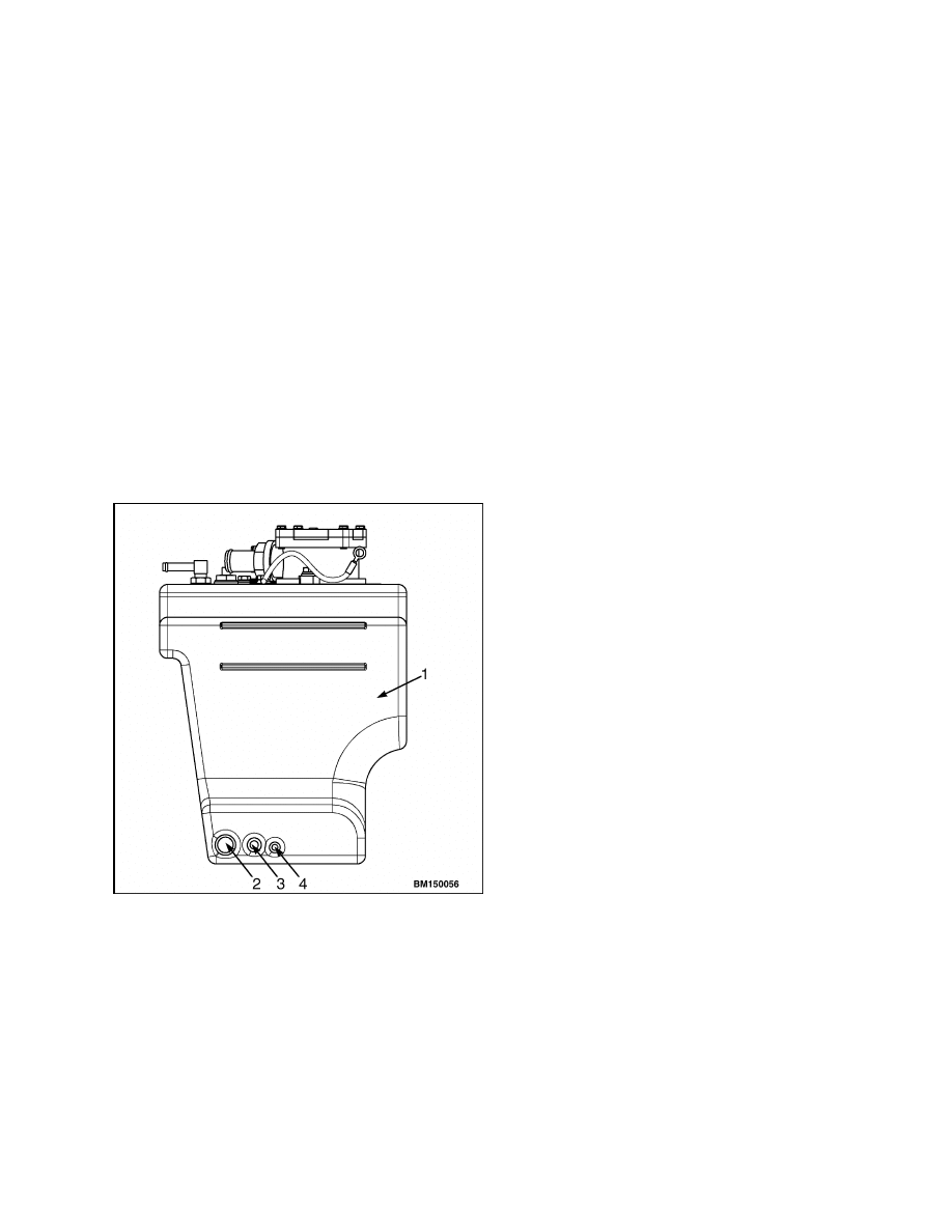
NOTE: Three hydraulic hoses attach to the bottom of
the hydraulic tank: the larger, lift pump supply hose,
the steering supply hose and the drain hose. The
drain hose exits the tank furthest from the larger,
lift pump supply hose and is coiled up and attached
to the lift supply hose using a wire tie. See Figure 5.
6.
Access the drain hose:
a. Reach under the bottom of the lift truck and
locate the access hole in the bottom of the lift
truck frame.
b. Reach into the hole and find the drain hose.
Using wire cutters, clip the wire tie retain-
ing the drain hose to the larger pump supply
hose and pull it through the access hole.
c.
Position the hose to drain into a container
suitable to collect the used hydraulic oil with
a minimum capacity of 19 liter (5 gal).
1.
HYDRAULIC TANK
2.
LIFT PUMP SUPPLY HOSE
3.
STEERING SUPPLY HOSE
4.
DRAIN HOSE
Figure 5. Hydraulic Tank Hoses
7.
Remove the hose clamp and drain plug from the
end of the drain hose to drain the hydraulic oil.
8.
When the oil has drained, reinstall the drain plug
into the hose and secure with hose clamp.
9.
Coil the drain hose and place it back inside the
access hole as removed.
Secure to larger hy-
draulic supply hose using a new wire tie.
10. Fill the hydraulic tank to the proper level
with new hydraulic oil. DO NOT overfill the
hydraulic tank. Refer to Capacities and Spec-
ifications 8000 SRM 1080 proper hydraulic oil
quantities and specifications.
NOTE: Check the hydraulic oil level by wiping the
dipstick clean and install the breather cap/dipstick
onto the tank. Remove again and check the oil level
on the dipstick.
11. Install the breather cap/dipstick.
12. Connect the battery connector and turn the key
switch to the ON position.
13. Operate the lift pump for 1 to 2 minutes to purge
air from the hydraulic system, then recheck the
hydraulic oil level.
14. Install the floormat and floor plates.
15. Lower the lift truck from blocks. See Periodic
Maintenance 8000 SRM 1079, How to Put Lift
Truck on Blocks.
16. Test for proper operation before returning to ser-
vice.
5
Hydraulic Tank Assembly
1900 SRM 1077
Hydraulic Tank Assembly
REMOVE
1.
Lower the forks completely and tilt the mast com-
pletely forward.
2.
Turn the key switch to the OFF position and dis-
connect the battery. Block the drive tires to pre-
vent unexpected movement.
3.
Remove the battery from the lift truck to improve
access to the lift pump.
4.
Remove the floormat and the floor plates.
WARNING
Use one piece, solid hardwood blocks to sup-
port the lift truck. Make sure the lift truck is
stable and secure before perfoming service.
5.
Position the lift truck on blocks approximately
305 mm (12 in.)
off the floor.
See Periodic
Maintenance 8000 SRM 1079, How to Put Lift
Truck on Blocks.
WARNING
Hydraulic oil is hot at normal operating tem-
peratures.
CAUTION
Disposal of lubricants and fluids must meet lo-
cal environmental regulations.
NOTE: Position a drip pan under the lift truck to
catch hydraulic oil spilled during the removal proce-
dures.
6.
Drain the hydraulic oil from the tank. Refer to
Hydraulic Oil, Change, in this section.
7.
Remove the hydraulic valve cover (manual valve
only).
8.
Remove the accelerator/brake pedal assembly
from the lift truck. Remove the brake line be-
tween the master cylinder and the tee fitting.
Cap the fittings on the master cylinder and the
tee fitting to prevent contamination.
9.
Tag and disconnect the steering return hose, the
tank return hose, and ground wire from the top
of the tank. See Figure 6.
Tag and disconnect the steering supply hose from the
steering pump and the lift pump supply hose from
the bottom of the lift pump through the access hole
in the battery compartment. See Figure 5.
10. Attach a sling and an overhead lifting device to
the tank. Tighten the lifting device to support
the weight of the tank.
11. Remove the hydraulic tank from the lift truck.
12. Remove hoses from the bottom of the tank if nec-
essary.
1.
CAPSCREW
2.
BREATHER CAP/DIPSTICK
3.
SCREW AND LOCKWASHER
4.
STRAINER ASSEMBLY
5.
CAPSCREW, LOCKWASHER, AND WASHER
6.
STEERING RETURN
7.
HYDRAULIC TANK
8.
GROUND WIRE
Figure 6. Hydraulic Tank Assembly
6

1900 SRM 1077
Hydraulic Tank Assembly
CLEAN
When cleaning the tank, do not use solutions that
produce dangerous gases at normal temperatures or
when heated. Wear eye and face protection and pro-
tective clothing to prevent burns.
When cleaning with pressurized water, use a hose
with a minimum diameter of 19 mm (0.75 in.). Con-
trol the pressure of the water using a valve installed
at the nozzle of the hose. If a metal nozzle is used,
it must be made of a non-sparking material. Main-
tain an electrical connection between the nozzle and
tank. Connect a ground wire to the tank to prevent
buildup of static electricity.
Trisodium Phosphate Method
If the tank cannot be cleaned with pressurized water,
use the following procedure:
1.
Mix a solution of water and trisodium phosphate
or a cleaning compound with an alkali base. Al-
ways follow the cleaner manufacturer’s recom-
mendations.
2.
Fill the tank with cleaning solution. Use com-
pressed air to mix the solution in the tank.
3.
Drain the tank.
4.
Flush the inside of tank with hot (boiling) water.
Make sure all cleaning compound and all loose
material is removed from inside of tank.
5.
Inspect the inside of tank using a light approved
for locations with flammable vapors.
6.
If the tank is not clean, repeat Step 1 through
Step 4 until tank is clean.
INSTALL
1.
Install hoses to the bottom of the tank, if re-
moved.
2.
Attach a sling and an overhead lifting device to
the tank. Position the tank into the lift truck.
3.
Install the steering supply hose to the steering
pump and, install the lift pump supply hose to
the lift pump inlet.
4.
Connect the steering return hose, the tank re-
turn hose, and ground wire to the top of the tank.
See Figure 6.
5.
Install the accelerator/brake pedal assembly to
the lift truck. Remove caps and install the brake
line between the master cylinder and the tee fit-
ting. Bleed air from the brake system.
6.
Fill the hydraulic tank to the proper level with
hydraulic oil.
Check the oil level using the
breather cap/dipstick.
DO NOT OVERFILL.
Install the breather cap/dipstick to the tank.
NOTE: Check the hydraulic oil level by wiping the
dipstick clean and installing the breather cap/dip-
stick onto the tank. Remove again and check the oil
level on the dipstick.
7.
Remove the drip tray from under the truck. Dis-
pose of waste oils properly.
8.
Purge air from the hydraulic system and check
for leaks.
a. Install the battery to the lift truck.
b. Connect the battery. Turn the key switch to
the ON position while seated in the seat.
c.
Raise and lower the mast several times.
Then completely lower the mast and tilt
forward until the forks touch the ground.
d. Turn the key switch to the OFF position and
disconnect the battery.
e.
Check for leaks around hose connections.
f.
Check the oil level using the breather cap/
dipstick. Add hydraulic oil to the proper level
if necessary.
9.
Install hydraulic valve cover (manual valve
only).
10. Install floor plates and floormat.
11. Remove blocks from the drive tires, connect the
battery, and test for proper operation before re-
turning lift truck to service.
7
Lift Pump and Motor
1900 SRM 1077
Lift Pump and Motor
REMOVE
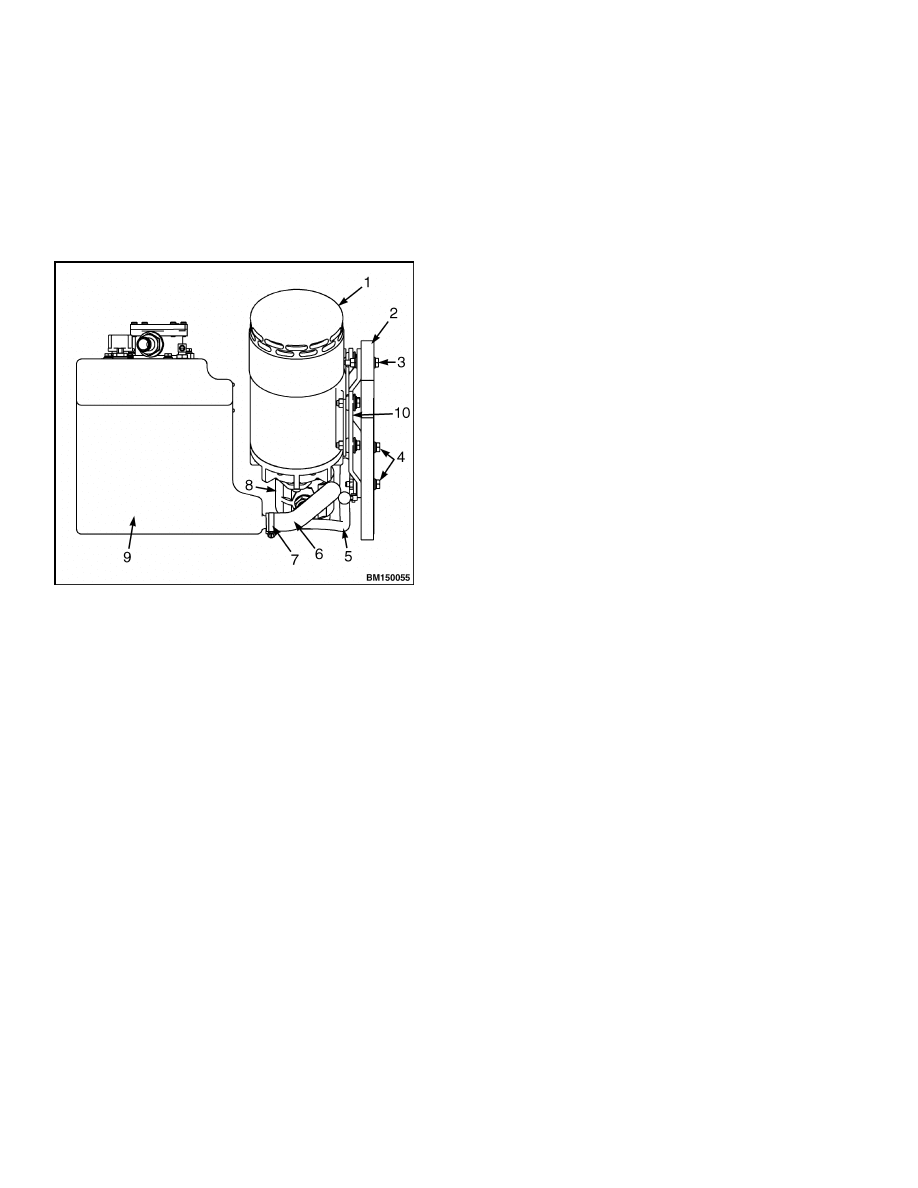
For the following procedures, refer to Figure 7.
1.
Lower the forks completely and tilt the mast com-
pletely forward.
1.
LIFT PUMP MOTOR
2.
FRAME
3.
TOP CAPSCREW
4.
LOWER SPACER STUD ASSEMBLIES
5.
DRAIN HOSE
6.
LIFT PUMP SUPPLY HOSE
7.
HOSE CLAMP
8.
LIFT PUMP
9.
HYDRAULIC TANK
10. MOUNTING PLATE
Figure 7. Lift Pump, Motor Assembly, and
Hydraulic Tank
2.
Turn the key switch to the OFF position and dis-
connect the battery. Block the drive tires to pre-
vent unexpected movement.
3.
Remove the battery from the lift truck to allow
access to the lift pump hydraulic lines.
4.
Remove the cover from the control valve.
5.
Remove the floormat and the floor plates.
6.
Position a drip pan under the lift truck to catch
hydraulic oil spilled during the removal proce-
dures.
7.
Drain the hydraulic oil from the tank. See Hy-
draulic Oil, Change, in this section.
8.
Tag and disconnect all electrical wires and hy-
draulic hoses from the lift pump and motor as-
sembly.
9.
Attach a sling and an overhead lifting device to
the lift pump and motor assembly. Tighten the
lifting device just enough to support the weight of
the assembly while removing the attaching hard-
ware.
10. Remove the top capscrew and washers retaining
the mounting plate of the lift pump and motor
assembly to the to the lift truck frame.
11. Lift the assembly off the lower spacer stud as-
semblies and from the truck using the overhead
lifting device.
12. Remove the lower spacer stud assemblies from
the frame if necessary.
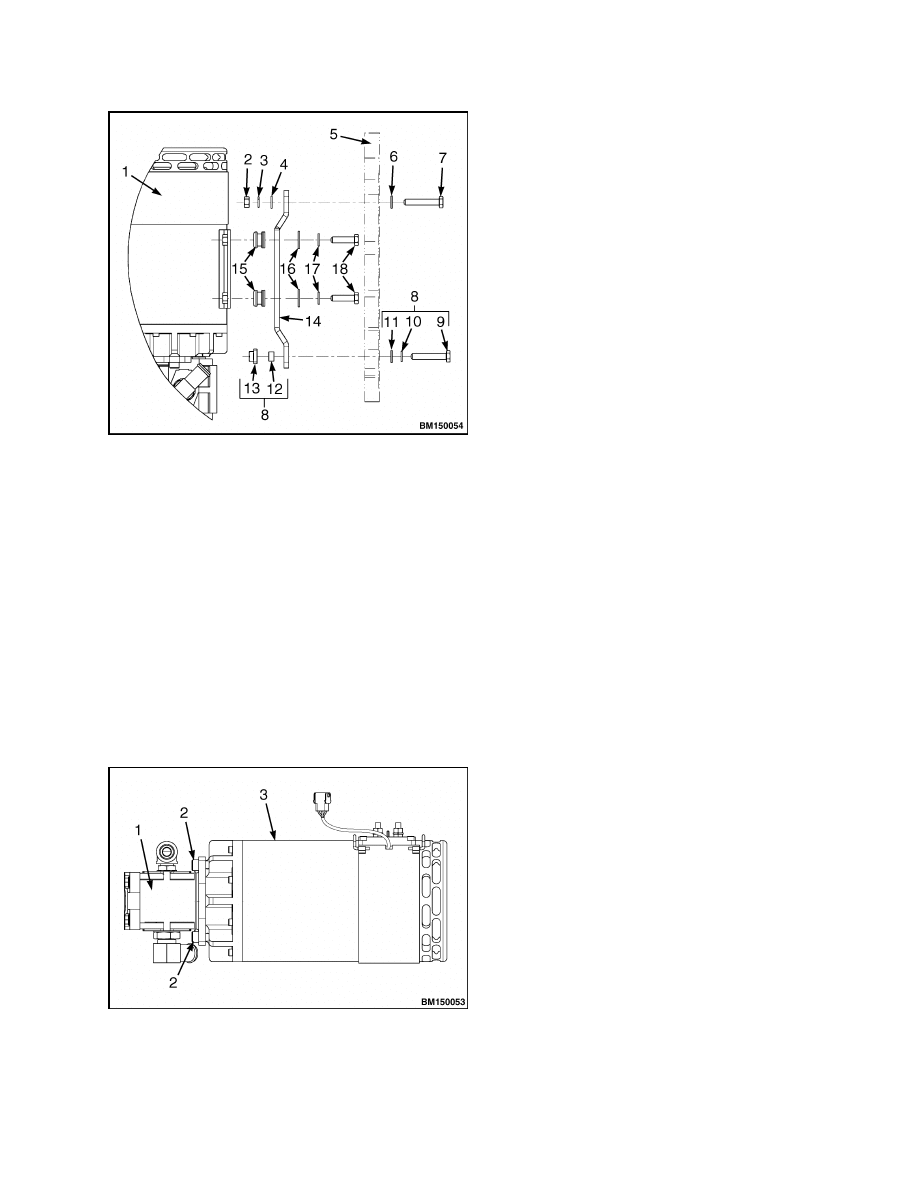
DISASSEMBLE
1.
Remove the capscrews and washers retaining the
mounting bracket to the lift pump and motor as-
sembly. See Figure 8.
2.
Remove the socket-head screws securing lift
pump to motor. See Figure 9.
3.
Separate lift pump from motor.
ASSEMBLE
1.
Slide pump onto motor shaft and align holes in
both housings.
2.
Install socket-head capscrews securing lift pump
to motor. Torque to 61 N•m (45 lbf ft). See Fig-
ure 9.
3.
Check the conditions of the isolator bushings.
Replace if necessary.
4.
Position the mounting bracket to the lift pump
and motor assembly and install the capscrews
and washers retaining the mounting bracket to
the lift pump and motor assembly. See Figure 8.
8
1900 SRM 1077
Lift Pump and Motor
1.
LIFT PUMP AND MOTOR ASSEMBLY
2.
NUT
3.
LOCKWASHER
4.
WASHER
5.
FRAME
6.
WASHER
7.
TOP CAPSCREW
8.
LOWER SPACER STUD ASSEMBLIES
9.
LOWER CAPSCREWS
10. LOCKWASHER
11. WASHER
12. SPACER
13. NUTPLATE
14. MOUNTING BRACKET
15. ISOLATOR BUSHINGS
16. WASHER
17. LOCKWASHER
18. CAPSCREWS
Figure 8. Mounting Bracket
Figure 9. Lift Pump and Motor Assembly
Legend for Figure 9
1.
LIFT PUMP
2.
SOCKET-HEAD SCREWS
3.
LIFT PUMP MOTOR
INSTALL
For the following procedures, refer to Figure 8.
1.
Install the lower spacer stud assemblies to the
frame if removed. Torque to 48 N•m (35 lbf ft).
2.
Position the lift pump and motor assembly into
the truck using the overhead lifting device. Slide
the mounting plate slots onto the lower spacer
studs.
3.
Install top capscrew, washers, and nut securing
mounting plate to frame.
Torque to 48 N•m
(35 lbf ft). Remove sling and lifting device.
4.
Connect electrical wiring and hydraulic hoses to
the assembly as removed.
5.
Fill the hydraulic tank to the proper level with
hydraulic oil.
Check the oil level using the
breather cap/dipstick. DO NOT OVERFILL.
6.
Purge air from the hydraulic system and check
for leaks:
a. Install the battery into the lift truck.
b. Connect the battery. Turn the key switch to
the ON position while sitting in the seat.
c.
Raise and lower the mast several times.
Then completely lower the mast and tilt
forward until the forks touch the ground.
d. Turn the key switch to the OFF position and
disconnect the battery.
e.
Visually inspect the hydraulic system for
leaks.
f.
Check the oil level again and fill to the proper
level, if necessary.
7.
Remove the drip tray from under the truck. Dis-
pose of waste oils properly.
9

Lift Pump
1900 SRM 1077
8.
Install floor plates and floormat.
9.
Install cover to the hydraulic valve.
10. Remove blocks from the drive tires, connect the
battery, and test for proper operation before re-
turning to service.
Lift Pump
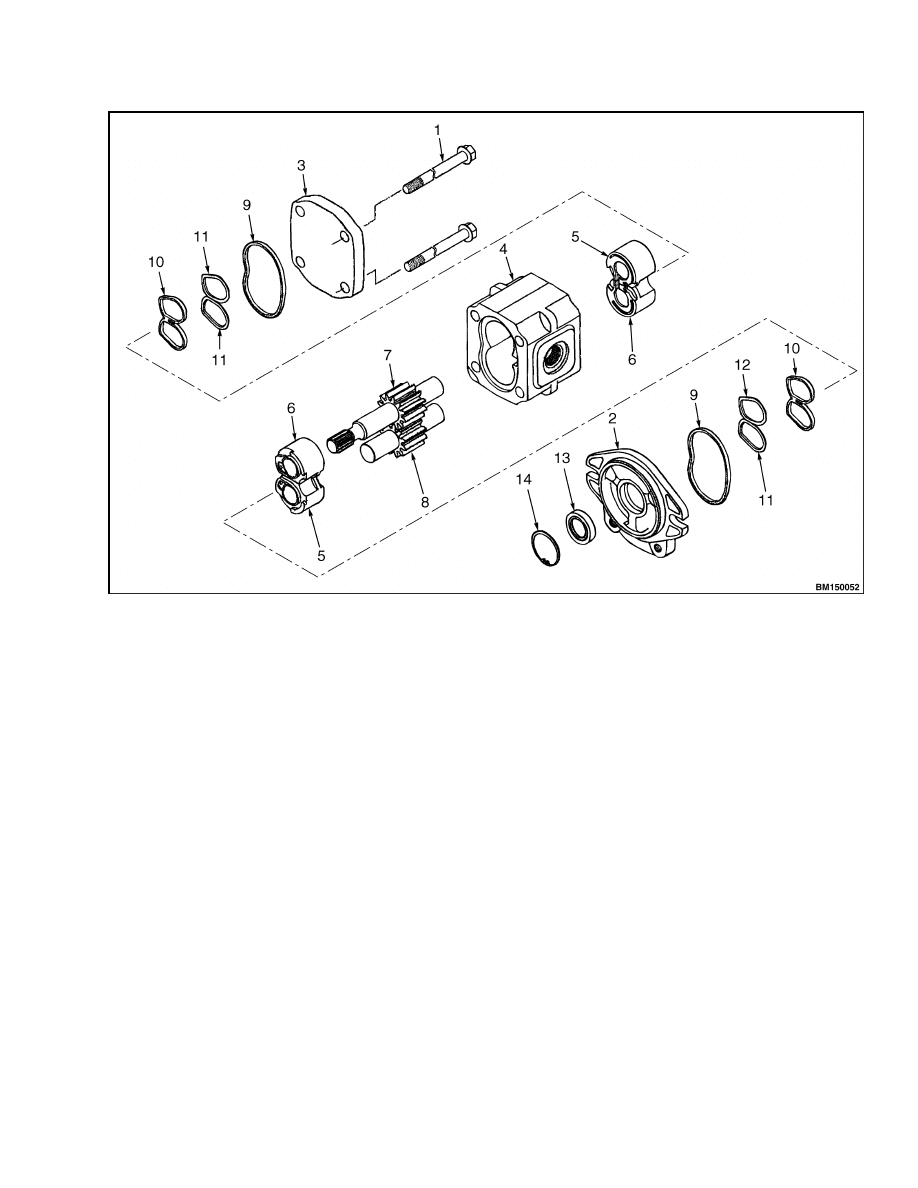
DISASSEMBLE
The lift pump must be removed from the lift truck
to disassemble. Check each component for signs of
wear. See Lift Pump and Motor for removal instruc-
tions. Place the pump on a clean workbench for dis-
assembly. Refer to Figure 10.
1.
Remove the lift pump and motor assembly from
the lift truck and remove the lift pump from the
motor. See Lift Pump and Motor.
NOTE: Make note of the orientation of the hydraulic
fittings to assist during assembly.
2.
Remove hydraulic fittings from pump assembly
if necessary.
3.
Remove capscrews securing the cover and the
mounting flange to the pump housing. Remove
the cover and mounting flange and collect the
seals (9).
4.
Remove the bushings (5, 6) from each end of the
pump housing. Remove seals (10) and rings (11)
from the bushings.
5.
Remove the gears (7, 8) from the pump housing.
6.
Inspect the bushings, gears, and the inside of the
pump housing for wear. Any component with no-
ticeable wear must be replaced. Check that the
gear shaft fits snugly in the bushings and is not
worn.
CAUTION
Be careful not to damage the flange when re-
moving the oil seal.
7.
Remove the snap ring from the mounting flange.
Drive the oil seal from the flange using a hammer
and a punch. See Figure 10.
ASSEMBLE
Thoroughly clean parts to be reused and assemble in
a clean environment.
CAUTION
Be careful not to damage the flange when in-
stalling the oil seal.
1.
Using a press, install the oil seal (13) into the
mounting flange (2). Install the snap ring (14).
2.
Install the gears (7, 8) to the pump housing.
3.
Install the seals (10) and rings (11) into the bush-
ings. Install the bushings (5, 6) to each end of the
pump housing onto the gear shafts.
4.
Install the seals (9) and position the cover and
mounting flange to the pump housing.
5.
Install four capscrews securing pump assembly
together and torque to 58 N•m (43 lbf ft).
6.
Install hydraulic fitting to the pump assembly, if
removed. Check O-rings for damage and replace
as necessary. Make certain that the hydraulic
fittings are oriented in the proper position for
installation of the hydraulic lines. Tighten fit-
tings to compress O-rings and seal the connec-
tions. DO NOT torque beyond 80 N•m (59 lbf ft).
10
1900 SRM 1077
Lift Pump
1.
SCREW
2.
MOUNTING FLANGE
3.
COVER
4.
PUMP HOUSING
5.
BUSHING
6.
BUSHING
7.
GEAR
8.
GEAR
9.
SEAL
10. SEAL
11. RING
12. RING
13. OIL SEAL
14. SNAP RING
Figure 10. Lift Pump Assembly
11

NOTES
____________________________________________________________
____________________________________________________________
____________________________________________________________
____________________________________________________________
____________________________________________________________
____________________________________________________________
____________________________________________________________
____________________________________________________________
____________________________________________________________
____________________________________________________________
____________________________________________________________
____________________________________________________________
____________________________________________________________
____________________________________________________________
____________________________________________________________
____________________________________________________________
____________________________________________________________
____________________________________________________________
____________________________________________________________
____________________________________________________________
12


TECHNICAL PUBLICATIONS
1900 SRM 1077
6/04 Printed in United Kingdom
Document Outline
- toc
Wyszukiwarka
Podobne podstrony:
1554635 8000SRM1079 (06 2004) UK EN
1554632 2000SRM1086 (06 2004) UK EN
897494 1900SRM0513 (06 2004) UK EN
1554635 8000SRM1079 (06 2004) UK EN
1554631 2000SRM1085 (03 2004) UK EN
1564283 1900SRM1107 (01 2004) UK EN
1565454 8000SRM1113 (06 2004) UK EN
1470232 1900SRM0783 (01 2004) UK EN
1554636 8000SRM1080 (11 2004) UK EN
1466217 1900SRM0743 (06 2005) UK EN
1554626 0100SRM1073 (06 2004) UK EN
897559 0100SRM0545 (06 2004) UK EN
897880 1400SRM0618 (06 2004) UK EN
897881 1600SRM0619 (06 2004) UK EN
1554631 2000SRM1085 (03 2004) UK EN
więcej podobnych podstron