FRAME
H40.00-52.00XM-16CH
(H1050, 1150HD-CH) [E117]
PART NO. 1566270
100 SRM 1118
SAFETY PRECAUTIONS
MAINTENANCE AND REPAIR
• When lifting parts or assemblies, make sure all slings, chains, or cables are correctly
fastened, and that the load being lifted is balanced. Make sure the crane, cables, and
chains have the capacity to support the weight of the load.
• Do not lift heavy parts by hand, use a lifting mechanism.
• Wear safety glasses.
• DISCONNECT THE BATTERY CONNECTOR before doing any maintenance or repair
on electric lift trucks. Disconnect the battery ground cable on internal combustion lift
trucks.
• Always use correct blocks to prevent the unit from rolling or falling. See HOW TO PUT
THE LIFT TRUCK ON BLOCKS in the Operating Manual or the Periodic Mainte-
nance section.
• Keep the unit clean and the working area clean and orderly.
• Use the correct tools for the job.
• Keep the tools clean and in good condition.
• Always use HYSTER APPROVED parts when making repairs. Replacement parts
must meet or exceed the specifications of the original equipment manufacturer.
• Make sure all nuts, bolts, snap rings, and other fastening devices are removed before
using force to remove parts.
• Always fasten a DO NOT OPERATE tag to the controls of the unit when making repairs,
or if the unit needs repairs.
• Be sure to follow the WARNING and CAUTION notes in the instructions.
• Gasoline, Liquid Petroleum Gas (LPG), Compressed Natural Gas (CNG), and Diesel fuel
are flammable. Be sure to follow the necessary safety precautions when handling these
fuels and when working on these fuel systems.
• Batteries generate flammable gas when they are being charged. Keep fire and sparks
away from the area. Make sure the area is well ventilated.
NOTE: The following symbols and words indicate safety information in this
manual:
WARNING
Indicates a condition that can cause immediate death or injury!
CAUTION
Indicates a condition that can cause property damage!

Frame
Table of Contents
TABLE OF CONTENTS
General ...............................................................................................................................................................
Description .........................................................................................................................................................
Counterweight Repair .......................................................................................................................................
Main Counterweight (Cast)...........................................................................................................................
Cover ..........................................................................................................................................................
Remove ..................................................................................................................................................
Install.....................................................................................................................................................
Counterweight ...........................................................................................................................................
Remove ..................................................................................................................................................
Install.....................................................................................................................................................
Rear Counterweight (Cast) ...........................................................................................................................
Remove.......................................................................................................................................................
Install .........................................................................................................................................................
Main Counterweight (Fabricated) ................................................................................................................
Remove.......................................................................................................................................................
Install .........................................................................................................................................................
Covers .................................................................................................................................................................
Remove ...........................................................................................................................................................
Install .............................................................................................................................................................
Floor Plates, Handrails, and Steps ...................................................................................................................
Hydraulic Tank Repair ......................................................................................................................................
Remove ...........................................................................................................................................................
Repair .............................................................................................................................................................
Small Leaks ...............................................................................................................................................
Large Leaks ...............................................................................................................................................
Clean ..............................................................................................................................................................
Steam Method............................................................................................................................................
Chemical Solution Method........................................................................................................................
Other Methods of Preparation for Repair ....................................................................................................
Install .............................................................................................................................................................
Suction Filters and Inspection Cover ...........................................................................................................
Remove.......................................................................................................................................................
Clean and Inspect......................................................................................................................................
Install .........................................................................................................................................................
Fuel Tank Repair ...............................................................................................................................................
Remove ...........................................................................................................................................................
Repair .............................................................................................................................................................
Install .............................................................................................................................................................
Engine Repair ....................................................................................................................................................
Remove ...........................................................................................................................................................
Install .............................................................................................................................................................
Label Replacement.............................................................................................................................................
This section is for the following models:
H40.00-52.00XM-16CH (H1050, 1150HD-CH) [E117]
©2004 HYSTER COMPANY
i

"THE
QUALITY
KEEPERS"
HYSTER
APPROVED
PARTS
100 SRM 1118
Description
General
This section has the description and repair proce-
dures for the lift truck frame and connected parts.
Included in this section are the frame, counter-
weight, covers, floor plates, handrails and steps,
hydraulic tank, and fuel tank.
The instructions
for removal and installation of the engine are also
included in this section.
Description
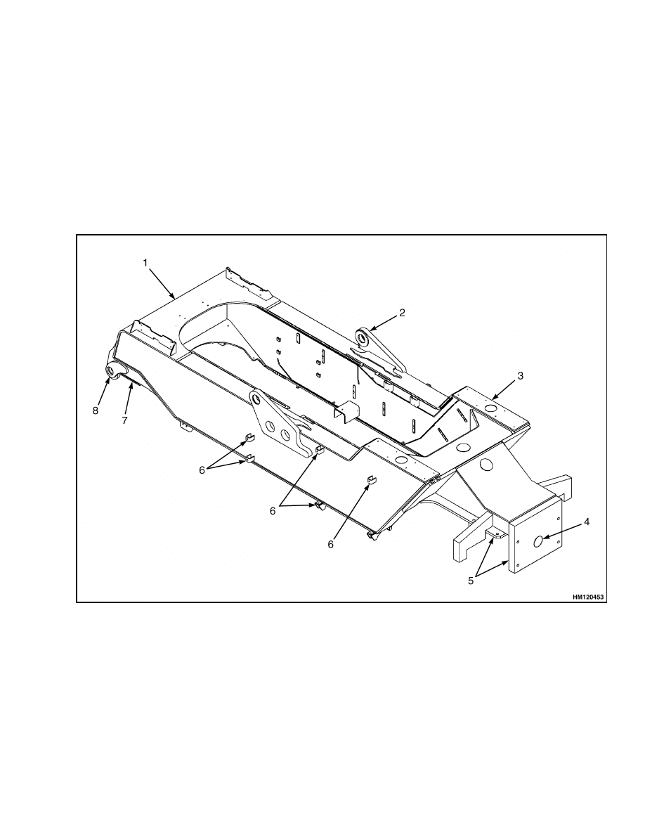
The frame is a one-piece weldment and has mounts
for the main counterweight, engine, transmission,
axles, hydraulic and fuel tanks, operator’s compart-
ment, and other parts. See Figure 1.
1.
MAIN FRAME
2.
TILT CYLINDERS MOUNT
3.
CAB SUPPORT MOUNT
4.
STEER AXLE MOUNT
5.
MAIN COUNTERWEIGHT MOUNT
6.
FUEL/HYDRAULIC TANK MOUNT
7.
DRIVE AXLE MOUNT
8.
MAST MOUNT
Figure 1. Frame
1
Counterweight Repair
100 SRM 1118
Counterweight Repair
MAIN COUNTERWEIGHT (CAST)
Cover
Remove
WARNING
The counterweight cover is a part of the lift
truck counterweight system and is very heavy.
Verify any lifting devices have the capacity to
lift 14,000 kg (30,865 lb).
1.
Place truck on solid, level surface.
2.
Lower the mast completely.
3.
Shut down the engine.
4.
Apply parking brake.
5.
Switch OFF the battery disconnect switch.
6.
Disconnect the two electrical cables on the com-
bination light assembly.
7.
Remove the two combination light assemblies
from the counterweight cover.
8.
Remove the four bolts attached to the fenders
and the two bolts attached on the main counter-
weight.
9.
Install lifting eyes and fasten a chain or cable.
10. Carefully lift the counterweight cover away from
the main counterweight and frame.
11. Lower the counterweight cover to the floor.
Install
1.
Install lifting eyes and fasten a chain or cable.
2.
Raise the counterweight cover and position above
the main counterweight.
3.
Align the holes of the counterweight cover with
the lifting points.
4.
Install the two bolts to the main counterweight.
5.
Tighten the two bolts to 1500 N•m (1106 lbf ft).
6.
Install the four bolts to the fenders.
7.
Install the two combination light assemblies.
8.
Connect the two electrical cables to the combina-
tion light assemblies.
9.
Switch ON the battery disconnect switch.
10. Verify all lights are functioning correctly.
Counterweight
Remove
WARNING
The main counterweight is very heavy. Verify
that the lifting devices and lift truck have the
capacity to lift 14,000 kg (30,865 lb).
Verify no one is under or gets under the main
counterweight being moved.
1.
Place truck on solid, level surface.
2.
Lower the mast completely.
3.
Shut down the engine.
4.
Apply the parking brake.
5.
Put forks of another lift truck under the main
counterweight.
6.
Remove cover. See Cover, Remove.
7.
Attach a lifting device to the four lift points of the
main counterweight.
8.
Remove the six tie rods that hold the main coun-
terweight to the frame.
WARNING
Never lift the counterweight straight up. This
will cause damage to the frame and may cause
personnel injury.
9.
Raise and move backward the main counter-
weight slowly at the same time.
10. Lower the main counterweight to the floor.
2
100 SRM 1118
Counterweight Repair
Install
1.
Put the forks of a lift under the counterweight.
2.
Attach a lifting device to the four lift points of the
main counterweight. See Figure 2.
3.
Install the counterweight on the frame by align-
ing the flange over the frame member.
4.
Install the tie rods, washers, and nuts. Tighten
the top tie rods to 700 N•m (516 lbf ft). Tighten
the rear tie rods to 1500 N•m (1106 lbf ft).
1.
MAIN COUNTERWEIGHT TIE RODS (6)
2.
MAIN COUNTERWEIGHT
3.
REAR COUNTERWEIGHT TIE RODS (4)
4.
REAR COUNTERWEIGHT
Figure 2. Counterweights
3
Counterweight Repair
100 SRM 1118
REAR COUNTERWEIGHT (CAST)
Remove
WARNING
The rear counterweight is part of the lift truck
counterweight system and is very heavy. Ver-
ify any lifting devices have the capacity to lift
7000 kg (15,432 lb).
1.
Place truck on solid, level surface.
2.
Lower the mast completely.
3.
Shut down the engine.
4.
Apply parking brake.
5.
Attach a lifting device to the two lift points of the
rear counterweight.
6.
Operate the lifting device just enough to give sup-
port to the rear counterweight.
7.
Remove the four tie rods that hold the rear coun-
terweight to the main counterweight.
8.
Carefully lift the rear counterweight away from
the main counterweight and lower to the floor.
Install
1.
Attach a lifting device to the two lift points of the
rear counterweight.
2.
Raise the rear counterweight to the lift truck.
3.
Align the dowels of the rear counterweight with
the holes in the main counterweight. Do not dis-
connect the chain sling.
4.
Install the tie rods, washers, and nuts. Tighten
the rear tie rods to 1500 N•m (1110 lbf ft).
MAIN COUNTERWEIGHT (FABRICATED)
Remove
WARNING
The counterweight is a part of the lift truck
counterweight system and is very heavy. Ver-
ify any lifting devices have the capacity to lift
14,000 kg (30,865 lb).
Verify no personnel is under or gets under the
counterweight when being moved.
1.
Place truck on solid, level surface.
2.
Lower the mast completely.
3.
Shut down the engine.
4.
Apply parking brake.
5.
Put forks of another lift truck under the counter-
weight.
6.
Attach a lifting device to the four lift points of the
counterweight.
7.
Remove the eight tie rods that hold the counter-
weight to the frame.
WARNING
Never lift the counterweight straight up. This
will cause damage to the frame and may cause
personnel injury.
8.
Raise and move backward the main counter-
weight slowly at the same time.
9.
Lower the main counterweight to the floor.
Install
1.
Put the forks of a lift truck under the counter-
weight.
2.
Attach a lifting device to the four lift points of the
counterweight.
3.
Install the counterweight on the frame by align-
ing the flange over the frame member.
4.
Install the tie rods, washers, and nuts. Tighten
the top tie rods to 700 N•m (516 lbf ft). Tighten
the rear tie rods to 1500 N•m (1106 lbf ft).
4
100 SRM 1118
Covers
Covers
REMOVE
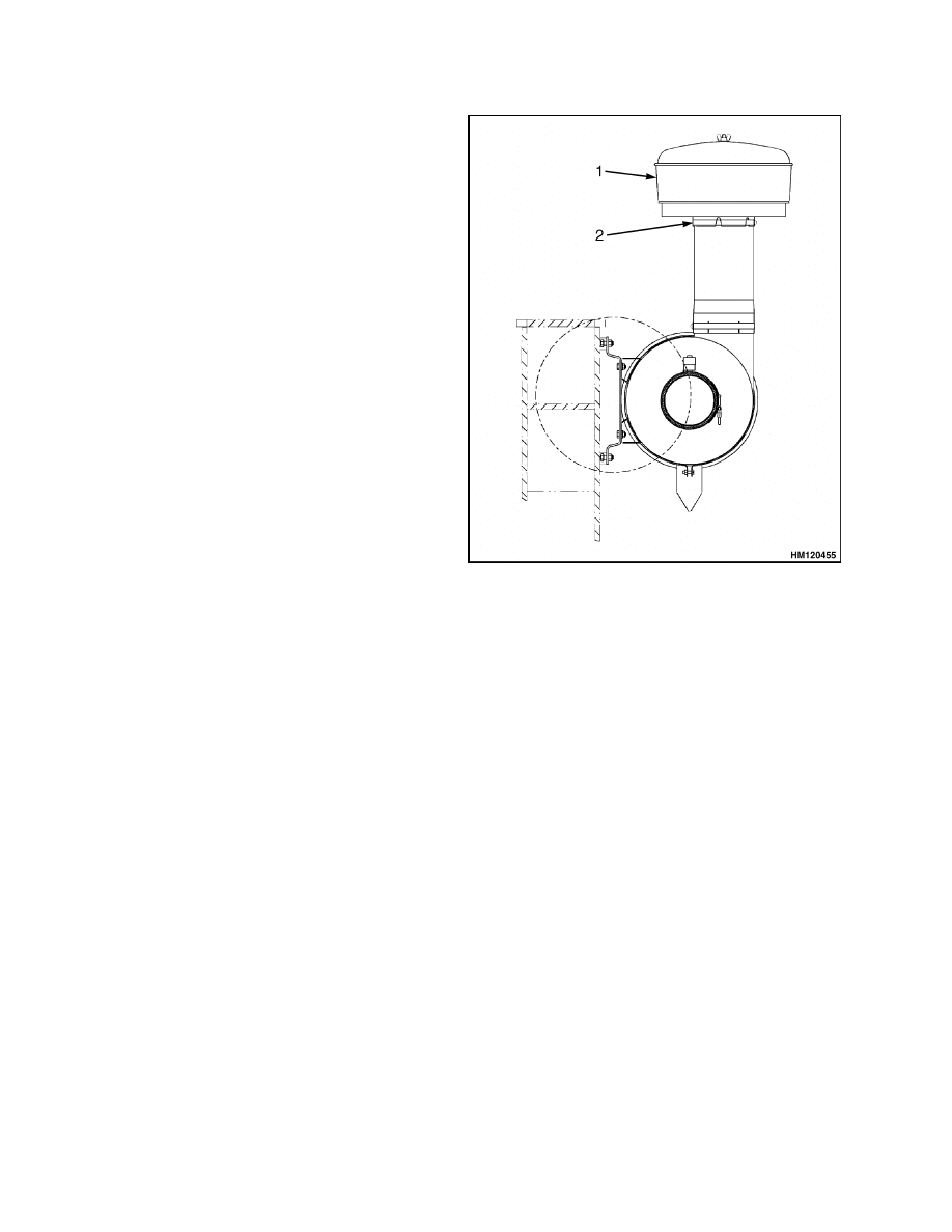
NOTE: The covers can be removed easily from the
frame using a lock/unlock system.
1.
Unlock the cover. See Figure 3.
NOTE: If necessary, remove the pre cleaner. See Fig-
ure 4.
2.
Remove the cover.
1.
PRE-CLEANER
2.
COVERS
Figure 3. Covers
5
Covers
100 SRM 1118
INSTALL
NOTE: If necessary, install the pre-cleaner. See Fig-
ure 4.
1.
Install the cover. See Figure 3.
2.
Lock the cover.
1.
PRECLEANER
2.
CLAMP
Figure 4. Precleaner
6
100 SRM 1118
Floor Plates, Handrails, and Steps
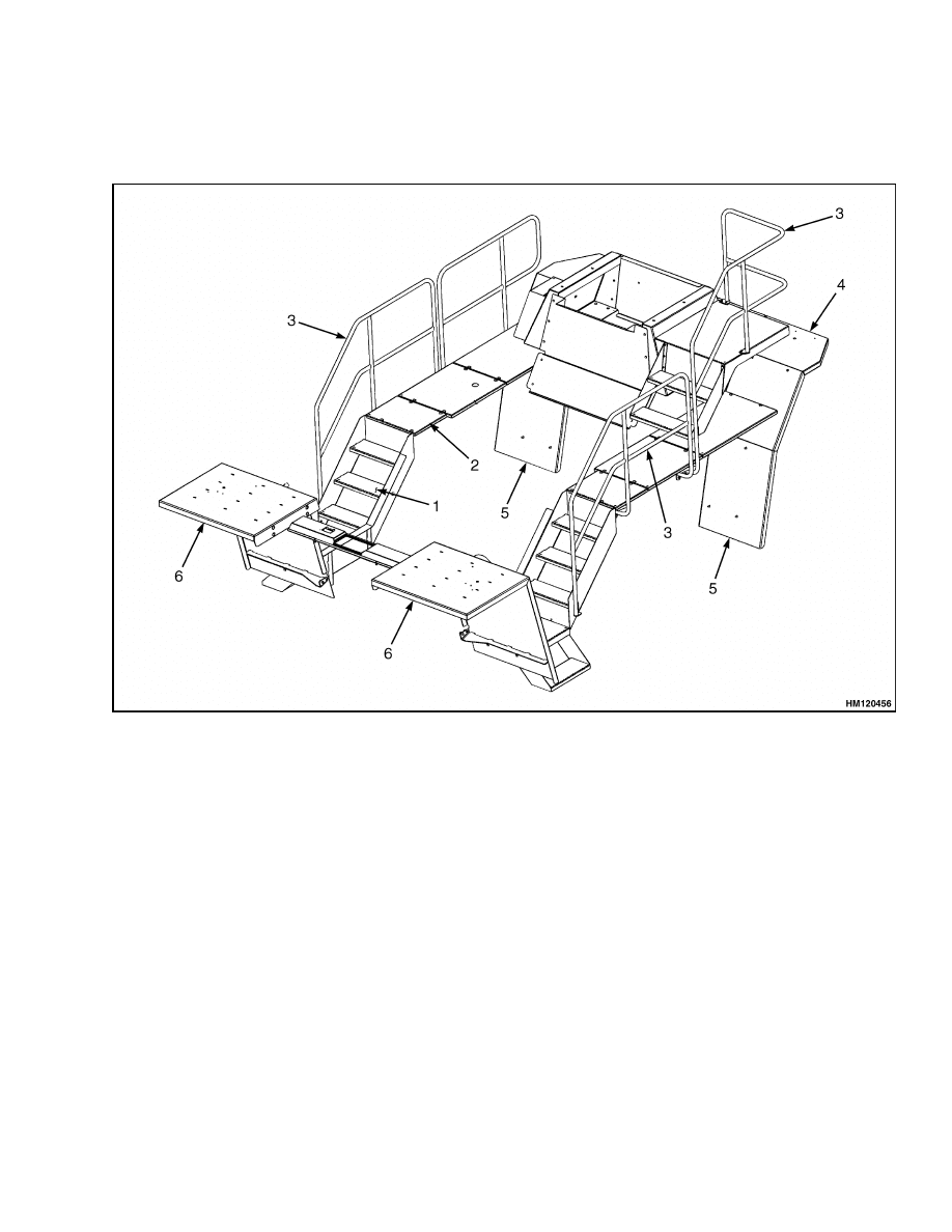
Floor Plates, Handrails, and Steps
The floor plates, handrails, and steps can be removed from the frame for access to components. See Figure 5.
1.
STEPS
2.
FLOOR PLATES
3.
HANDRAILS
4.
COVER
5.
REAR FENDER
6.
FRONT FENDER
Figure 5. Floor Plates, Handrails, and Steps
7
Hydraulic Tank Repair
100 SRM 1118
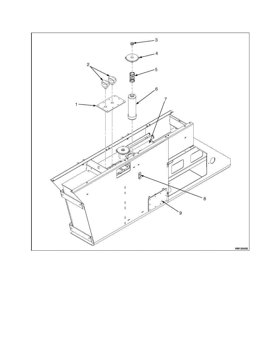
Hydraulic Tank Repair
The hydraulic tank is installed on the right side of
the frame. See Figure 6.
REMOVE
WARNING
The hydraulic oil tank contains 700 liter
(185 gal) of hydraulic oil. Drain the oil from
the tank before removing the hydraulic tank.
Failure to drain the tank could result in an oil
spill.
After use of the hydraulic system, the hy-
draulic oil is very hot.
Do not begin any
maintenance procedures until the hydraulic
oil has cooled. Monitor the temperature of the
hydraulic oil by observing the temperature
gauge on the outside of the hydraulic tank.
1.
Place truck on solid, level surface.
2.
Lower the mast completely.
3.
Shut down the engine.
4.
Apply the brake.
5.
Close shutoff valves on bottom of hydraulic tank.
6.
Disconnect the hoses at the shutoff valves.
7.
Put caps in the open holes of the valves.
8.
Use a pan to catch the oil that is in the hydraulic
lines.
9.
Remove the drain plug at the bottom of the tank
to drain the oil into clean barrels.
10. Disconnect the hydraulic lines at the bottom of
the hydraulic tank.
11. Disconnect the hydraulic return lines at the up-
per front of the hydraulic tank.
12. Use a pan to catch the oil that is in the hydraulic
lines.
13. Put tags on the lines for identification.
14. Put caps on the open lines and fittings.
CAUTION
These lift trucks have a 24-volt electrical
system (two 12-volt batteries in series).
The
higher voltage can cause an electrical shock.
Always move battery disconnect switch to
disconnected position (pointer to left) before
working on electrical system.
For trucks with ECM (engine control module),
battery disconnect should only be performed
after switching OFF ignition for 30 seconds.
15. Disconnect all electrical connectors from the hy-
draulic tank and tag connectors to aid in the in-
stallation.
WARNING
Batteries are very heavy and should not be
lifted without assistance or personnel injury
may occur.
16. Disconnect the cables from the batteries, and re-
move the batteries through the access door.
17. Remove handrails, walkway covers, and lower
step from the hydraulic tank.
18. Remove rear fender.
19. Attach a lifting device to the hydraulic tank at
the two lifting eyes.
20. Create tension on the chains.
21. Position the lifting device so hydraulic tank will
be moved a little toward the frame.
22. Remove the six capscrews holding hydraulic tank
to the frame.
WARNING
The hydraulic tank weighs 600 kg (1323 lb).
Verify the lifting device has the rated capacity
to remove the hydraulic tank.
CAUTION
Verify the hydraulic hose and electrical cables
are not damaged during the removal of the hy-
draulic tank.
23. Carefully lift the hydraulic tank from the lift
truck frame.
8
100 SRM 1118
Hydraulic Tank Repair
1.
COVER
2.
BREATHER
3.
PLUG
4.
COVER AND GASKET
5.
SPRING
6.
FILTER
7.
HYDRAULIC TANK
8.
INDICATOR
9.
INSPECTION COVER
Figure 6. Hydraulic Tank Assembly
9

Hydraulic Tank Repair
100 SRM 1118
REPAIR
Small Leaks
NOTE: See the section Steam Method for prepara-
tions for leak repairs.
WARNING
Do not use tools that can make sparks, heat, or
static electricity. The vapors in the tank can
cause an explosion.
1.
Use steam to clean the area around the leak. Re-
move all paint and dirt around the leak.
2.
Apply Loctite 290
®
to the leak. Follow the in-
structions of the manufacturer.
Large Leaks
NOTE: See the section Steam Method for prepara-
tions for leak repairs.
1.
Use acceptable welding practices to repair the
tank.
See the American National Standard
Safety in Welding and Cutting AWS Z 49.1 -
1999.
CLEAN
WARNING
The power connect to the ECM (electronic con-
trol module) must be disconnected before weld-
ing on the vehicle. This is accomplished by dis-
connecting the 50-pin OEM interface connec-
tor. Ground for the welder must be located as
near as possible to the welding location. Never
attach the welder ground clamp to the ECM.
Special procedures must be followed when
large leaks or other repairs need welding or
cutting. All work must be done by authorized
personnel. If the tank is cleaned inside of a
building, make sure there is enough ventila-
tion. See the following manuals for additional
information:
• "Safe Practices for Welding and Cutting Con-
tainers That Have Held Combustibles" by the
American Welding Society, F4.1 - 1999.
• "Safety In Welding and Cutting," American
National Standard, AWS Z 49.1 - 1999.
When cleaning the tank, do not use solutions that
make dangerous gases at normal temperatures or
when heated. Wear device for the protection of the
eyes. Protect the body from burns.
When cleaning with steam, use a hose with a mini-
mum diameter of 19 mm (0.75 in.). Control the pres-
sure of the steam by a valve installed at the nozzle of
the hose. If a metal nozzle is used, it must be made of
a material that does not make sparks. Make an elec-
trical connection between the nozzle and the tank.
Connect a ground wire to the tank to prevent static
electricity.
Steam Method
1.
Remove all the parts from the hydraulic tank,
except inspection cover.
2.
Install the drain plug.
3.
Fill the tank 1/4 full with a solution of water and
sodium bicarbonate or sodium carbonate. Mix
0.5 kg (1 lb) per 4 liter (1 gal) of water.
4.
Mix the solution in the tank using compressed
air. Verify all the surfaces on the inside of the
tank are flushed with the solution.
5.
Drain the tank.
6.
Put steam into the tank until the tank does not
have odors and the metal is hot. Steam vapors
must come from all the openings.
7.
Flush the inside of the tank with boiling water.
Verify all the loose material is removed from the
inside of the tank.
8.
Make an inspection of the inside of the tank. If
it is not clean, repeat Step 6 and Step 7 and
make another inspection. When making inspec-
tions, use light that is approved for locations with
flammable vapors.
9.
Put plugs in all the openings in the tank. Wait 15
minutes; then remove the inlet and outlet plugs.
Test a sample of the vapor with a special indi-
cator for gas vapors. If the amount of flammable
vapors is above the lower flammable limit, repeat
the cleaning procedures.
10
100 SRM 1118
Hydraulic Tank Repair
Chemical Solution Method
NOTE: If the tank cannot be cleaned with steam, use
the following procedure:
1.
Mix a solution of water and trisodium phosphate
or a cleaning compound with an alkali base. Fol-
low the instructions given by the manufacturer.
2.
Fill the tank with the cleaning solution. Use com-
pressed air to mix the solution in the tank.
3.
Drain the tank. Flush the inside of the tank with
hot (boiling) water. Make sure all the cleaning
compound is removed.
4.
Make an inspection of the inside of the tank. If
the tank is not clean, repeat Step 1, Step 2, and
Step 3. Make another inspection of the tank.
When making inspections, use a light that is ap-
proved for locations with flammable vapors.
5.
Check the tank for flammable vapors using a
special indicator for gas vapors. If the amount
of flammable vapors is not below the lower
flammable limit, repeat the cleaning procedures.
OTHER METHODS OF PREPARATION FOR
REPAIR
If nitrogen gas or carbon dioxide gas is available, pre-
pare the tank for welding using these gases. See the
manual Safe Practices for Welding and Cutting Con-
tainers That Have Held Combustibles by the Ameri-
can Welding Society, F4.1 - 1999. If these gases are
not available, another method using water can be
used as follows:
1.
Fill the tank with water to just below the point
where the work will be done.
Make sure the
space above the level of the water has a vent.
2.
Use acceptable welding practices to repair the
tank.
See the American National Standard
Safety In Welding and Cutting AWS Z 49.1 -
1999.
INSTALL
WARNING
The hydraulic oil tank contains 700 liter
(185 gal) of hydraulic oil. Drain the oil from
the tank before removing the hydraulic tank.
Failure to drain the tank could result in an oil
spill.
1.
Attach a lifting device to the hydraulic tank at
the two tank mounts.
2.
Raise the hydraulic tank and put the hydraulic
tank in position on the frame.
3.
Install the six capscrews that hold the hydraulic
tank to the frame.
4.
Install lower step, walkway covers, and handrail
onto hydraulic tank.
5.
Install rear fender onto hydraulic tank
6.
Connect all electrical connectors as tagged dur-
ing removal.
WARNING
Batteries are very heavy and should not be
lifted without assistance or personnel injury
may occur.
7.
Install the batteries through the access door, and
connect the cables to the batteries.
8.
Connect the hydraulic return lines located at the
upper front of the hydraulic tank.
9.
Connect the hydraulic lines at the bottom of the
hydraulic tank.
WARNING
Before filling the hydraulic tank with hy-
draulic oil, replace the seal rings and gasket to
avoid oil leakage. See Figure 7.
10. Fill the hydraulic tank to the correct level with
the oil specified in the Maintenance Schedule ta-
ble in the section Periodic Maintenance 8000
SRM 1154.
CAUTION
Never start the engine with closed shutoff
valves. Open the shutoff valves before starting
the engine to prevent damage to hydraulic
components.
11. Start the engine and operate the hydraulic sys-
tem. Verify all functions work correctly.
11
Hydraulic Tank Repair
100 SRM 1118
WARNING
Do not try to locate hydraulic leaks by putting
hands on pressurized hydraulic components.
Hydraulic oil can be injected into the body and
cause personnel injury.
12. Check for leaks.
13. Bleed the system.
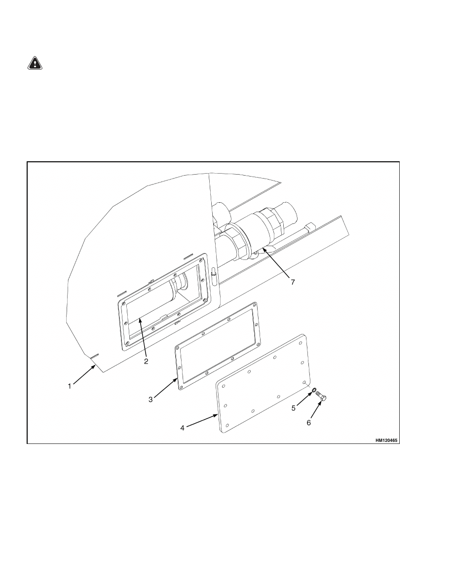
SUCTION FILTERS AND INSPECTION
COVER
Remove
NOTE: To drain hydraulic oil from the tank, see Re-
move, Step 9.
1.
Drain hydraulic oil from the hydraulic tank.
2.
Remove the bolts of the inspection cover. See Fig-
ure 7.
1.
HYDRAULIC TANK
2.
SUCTION FILTER
3.
GASKET
4.
INSPECTION COVER
5.
SEAL RING (10)
6.
BOLT (10)
7.
SHUTOFF VALVES
Figure 7. Suction Filters and Inspection Cover
12
100 SRM 1118
Fuel Tank Repair
3.
Remove seal rings.
4.
Remove inspection cover.
NOTE: Remove suction filters by turning counter-
clockwise.
5.
Remove suction filters.
Clean and Inspect
NOTE: Verify seal rings are in good condition. Re-
place, if necessary.
1.
Clean seal rings.
NOTE: Verify gasket is in good condition. Replace, if
necessary.
2.
Clean gasket.
NOTE: If condition of the suction filters is in doubt,
replace suction filters.
3.
Inspect suction filters.
Install
NOTE: Only use seal rings specified by your lift truck
dealer. Using seal rings or washers other than spec-
ified will lead to hydraulic oil leakage.
NOTE: Install suction filters by turning clockwise.
1.
Install suction filters.
2.
Install gasket and inspection cover using seal
rings and bolts.
3.
Tighten bolts to 51 N•m (38 lbf ft).
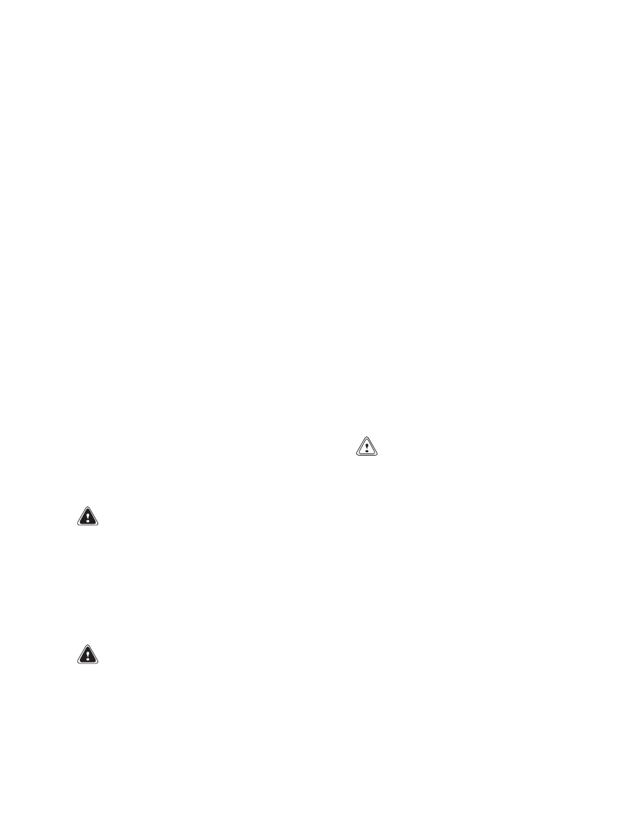
Fuel Tank Repair
The fuel tank is installed on the left-hand frame
channel. See Figure 8.
REMOVE
1.
Place truck on solid, level surface.
2.
Lower the mast completely.
3.
Shut down the engine.
4.
Apply the parking brake.
WARNING
When removing the fuel tank, do not use tools
that can make sparks, heat, or static electricity.
The vapors in the tank can cause an explosion
and personnel injury may occur.
5.
Put a drain pan under the fuel tank.
6.
Remove drain plug to drain the fuel from the
tank.
WARNING
If the fuel is drained from the fuel tank, put the
fuel in a can or barrel that has a sealed cap to
prevent contamination.
7.
Disconnect the fuel lines at the tank.
8.
Remove handrails, walkway covers, and steps
from the fuel tank.
9.
Remove rear fender.
CAUTION
These lift trucks have a 24-volt electrical
system (two 12-volt batteries in series).
The
higher voltage can cause an electrical shock.
Always move battery disconnect switch to
disconnected position (pointer to left) before
working on electrical system.
10. Disconnect all electrical connectors from the fuel
tank and tag connectors to aid in the installation.
11. Attach a lifting device to the fuel tank at the two
tank mounts.
12. Create tension on the chains.
13. Position the lifting device so fuel tank will be
moved a little toward the frame.
14. Remove the six capscrews that hold fuel tank to
the frame.
13
Fuel Tank Repair
100 SRM 1118
1.
FUEL TANK
2.
FUEL GAUGE SENDER
3.
COVER
4.
FILLER CAP
5.
DRAIN PLUG
Figure 8. Fuel Tank Assembly
14
100 SRM 1118
Engine Repair
WARNING
The fuel tank weighs 600 kg (1323 lb). Verify
the lifting device has the rated capacity to lift
the fuel tank.
15. Carefully lift the fuel tank from the lift truck
frame.
REPAIR
WARNING
Do not use tools that can make sparks, heat, or
static electricity. The vapors in the tank can
cause an explosion.
Repair the fuel tank as described in the repair proce-
dures for the hydraulic tank.
INSTALL
1.
Attach a lifting device to the fuel tank at the two
tank mounts.
WARNING
The fuel tank weighs 600 kg (1323 lb). Verify
the lifting device has the rated capacity to lift
the fuel tank.
2.
Raise fuel tank and put in position on the frame.
3.
Install the six capscrews that hold fuel tank to
the frame. Tighten to 51 N•m (38 lbf ft).
4.
Install the steps, walkway covers, and handrails
to the fuel tank.
5.
Install rear fender to the fuel tank.
6.
Connect all electrical connectors as tagged dur-
ing removal.
7.
Connect fuel lines to the tank.
8.
Fill fuel tank to correct level with fuel specified
in the Maintenance Schedule of the section Pe-
riodic Maintenance 8000 SRM 1154.
9.
Start engine.
10. Check for leaks.
Engine Repair
REMOVE
CAUTION
Battery disconnect should only be performed
at least 30 seconds after switching OFF igni-
tion.
Remove the engine as follows:
1.
Place truck on solid, level surface.
2.
Lower the mast completely.
3.
Shut down the engine.
4.
Apply parking brake.
CAUTION
Remove the ground cable first.
5.
Disconnect the cables at the battery.
WARNING
Verify the lifting device has the rated capacity
of 2500 kg (5512 lb).
6.
Attach a lifting device and sling to the hood pan-
els.
NOTE: Do not remove the hood panel located above
the air cleaner.
7.
Remove the hood panels.
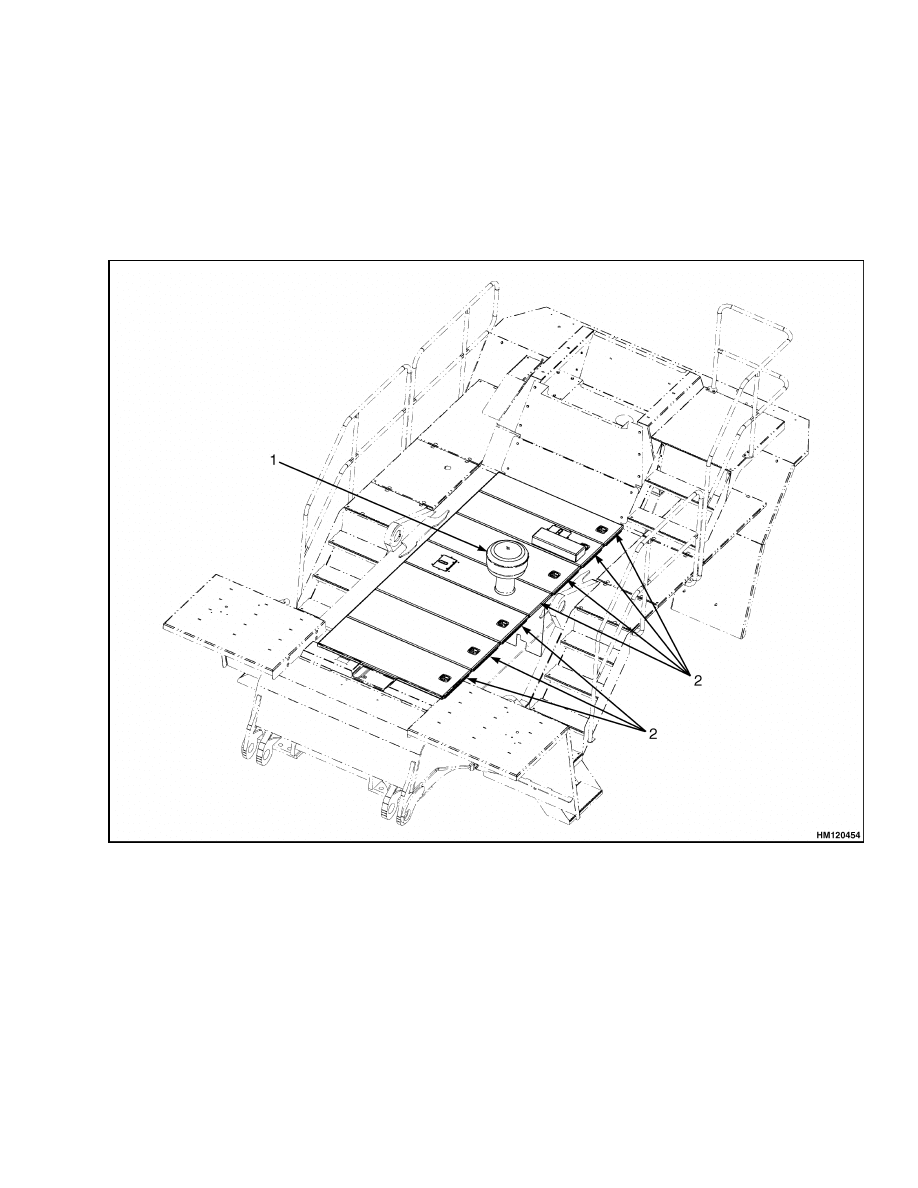
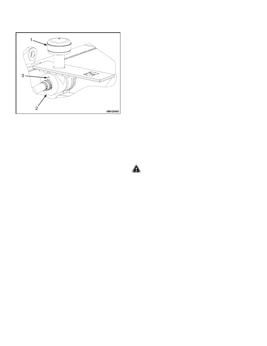
8.
Remove the precleaner and pipe from the air
cleaner. See Figure 9.
9.
Remove the hood panel located above the air
cleaner.
10. Remove the rubber elbow between the engine
and air cleaner.
15
Engine Repair
100 SRM 1118
1.
PRECLEANER
2.
AIR CLEANER
3.
ELECTRONIC RESTRICTION INDICATOR
Figure 9. Engine Air Cleaner
11. Remove the air cleaner.
12. Drain the coolant from the cooling system.
NOTE: Do not disconnect the cooling lines from the
radiator.
13. Disconnect the cooling lines from the engine.
14. Remove the capscrews to the fan through the in-
spection cover.
15. Remove the fan.
16. Close shutoff valves on the bottom of the hy-
draulic tank.
NOTE: Use a pan to catch the oil in the hydraulic
lines.
17. Disconnect the hydraulic lines at the pumps.
18. Put tags on the lines for identification.
19. Put caps on open lines and fittings.
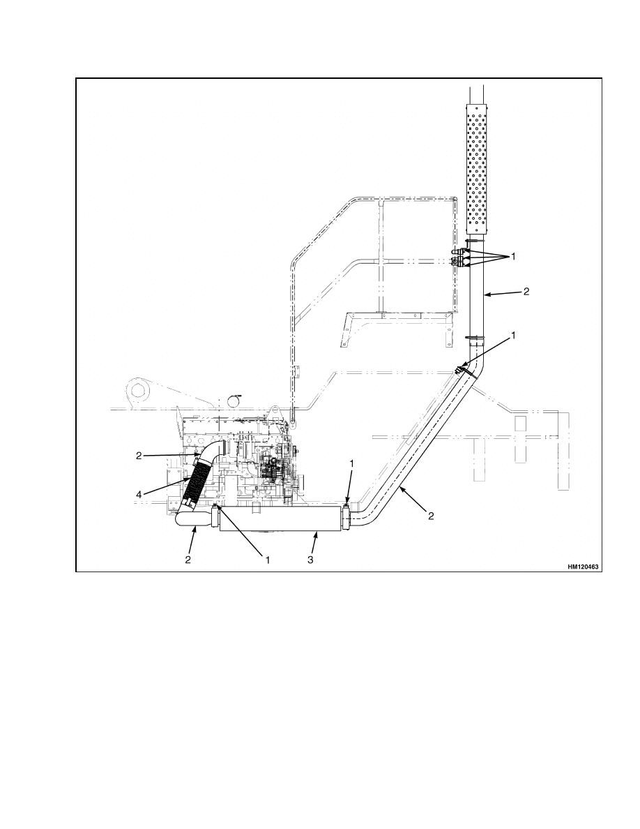
20. Disconnect the flexible tube, attached to the en-
gine, from the exhaust pipe. See Figure 10.
21. Disconnect fuel lines at the fuel filter.
22. Disconnect electric wires and wiring harnesses
from the engine.
23. Disconnect the starter cable from the starter.
24. Disconnect the electrical wires from the trans-
mission.
25. Disconnect the cooling lines from the transmis-
sion.
26. Remove the U-joint from the transmission.
27. Disconnect hydraulic lines from the transmission
to the hydraulic filter.
28. Put caps on the hydraulic lines.
29. Disconnect the charge air cooler lines from the
charge air cooler core on the radiator.
30. Disconnect the lines from the expansion tank.
31. Disconnect the drive shaft from the transmis-
sion.
WARNING
Verify the lifting device has the rated capacity
of at least 2500 kg (5512 lb) or personnel injury
may occur.
32. Connect a lifting device to the engine and trans-
mission.
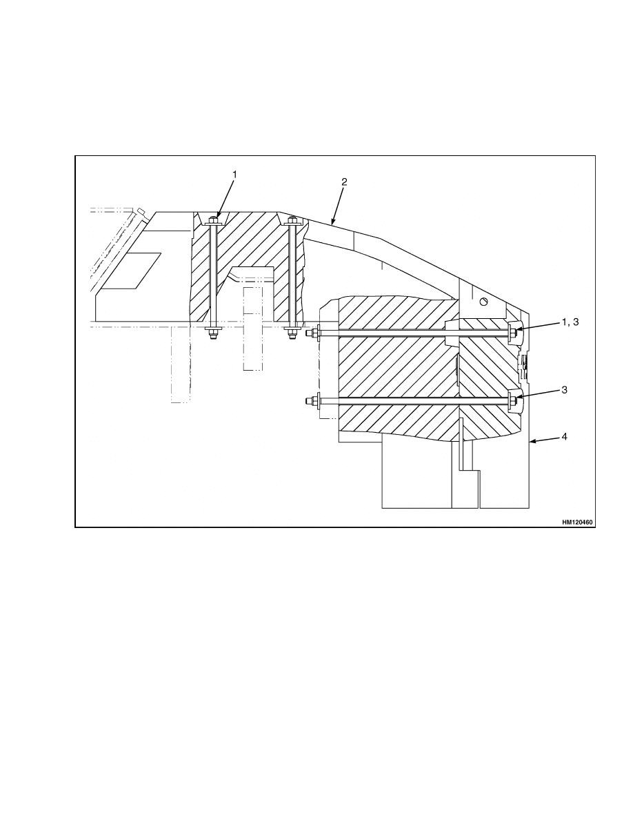
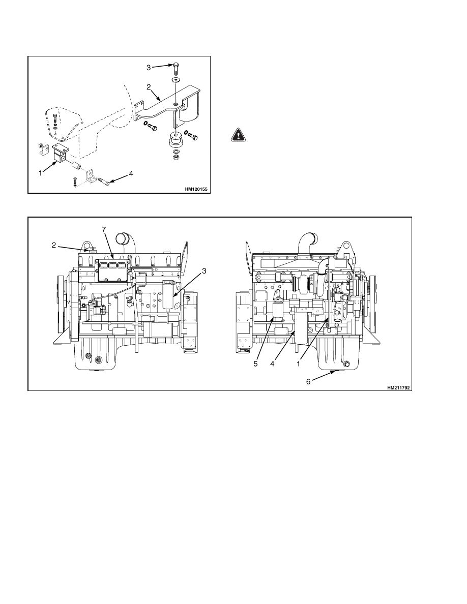
33. Remove the engine mount capscrews that hold
the engine mount at the fan end of the engine.
See Figure 11.
34. Remove the front mount capscrews that hold the
two front mount brackets to the engine. See Fig-
ure 11.
35. Carefully lift the engine and transmission as-
sembly from the frame. See Figure 12. Verify
all the connections to the engine or transmission
have been removed.
16
100 SRM 1118
Engine Repair
1.
LOCK NUT
2.
EXHAUST TUBE
3.
MUFFLER
4.
FLEX TUBE
Figure 10. Exhaust System
17
Engine Repair
100 SRM 1118
Figure 11. Engine Mounts
Legend for Figure 11
1.
REAR MOUNT (FAN END OF ENGINE)
2.
FRONT MOUNT
3.
FRONT MOUNT CAPSCREW
4.
ENGINE MOUNT CAPSCREW
INSTALL
WARNING
Verify the lifting device has the rated capacity
of at least 2500 kg (5512 lb).
1.
Connect a lifting device to the engine and trans-
mission.
2.
Install the engine and transmission assembly in
the frame.
1.
DIPSTICK
2.
ENGINE OIL FILL CAP
3.
FUEL FILTER
4.
OIL FILTER
5.
COOLANT FILTER
6.
ENGINE OIL DRAIN PLUG
7.
ECM
Figure 12. Engine Assembly
3.
Install and tighten the nuts and bolts for the en-
gine mounts.
4.
Connect the U-joint to the torque converter.
5.
Tighten the bolts for the universal joint to
68 N•m (50 lbf ft).
6.
Connect the lines to the expansion tank.
7.
Connect the charge air cooler lines to the charge
air cooler core on the radiator.
8.
Connect hydraulic lines from the transmission to
the hydraulic filter.
9.
Connect the cooling lines to the transmission.
10. Connect the electric wires to the transmission.
18
100 SRM 1118
Label Replacement
11. Connect the starter cable to the starter.
12. Connect electric wires and wire harnesses to the
engine.
13. Install the fuel lines between the fuel filter on the
engine assembly and fuel tank and water separa-
tor.
14. Connect the flexible tube, attached to the engine,
from the exhaust pipe using a new pipe clamp.
15. Connect the hydraulic lines to the hydraulic
pumps.
CAUTION
Never start the engine with closed shutoff
valves. Open the shutoff valves before starting
the engine to prevent damage to hydraulic
components.
16. Open the valves on the hydraulic tank.
17. Mount the fan to the engine.
18. Install the capscrews to the fan through the in-
spection cover.
19. Install the air cleaner.
20. Connect the rubber elbow between the engine
and air cleaner.
21. Connect the cooling lines to the engine.
22. Fill cooling system with coolant.
23. Connect the drive shaft to the transmission.
24. Check all oil levels.
CAUTION
Install the power cable first or lift truck dam-
age may occur.
25. Connect the cables to the battery.
26. Install the hood panel above the air cleaner.
27. Install the precleaner and pipe from the air
cleaner.
28. Start the engine and check for leaks and correct
operation.
WARNING
Verify the lifting device has the rated capacity
of 5512 kg (2500 lb).
29. Attach a lifting device and sling to the hood pan-
els.
30. Install the hood panels.
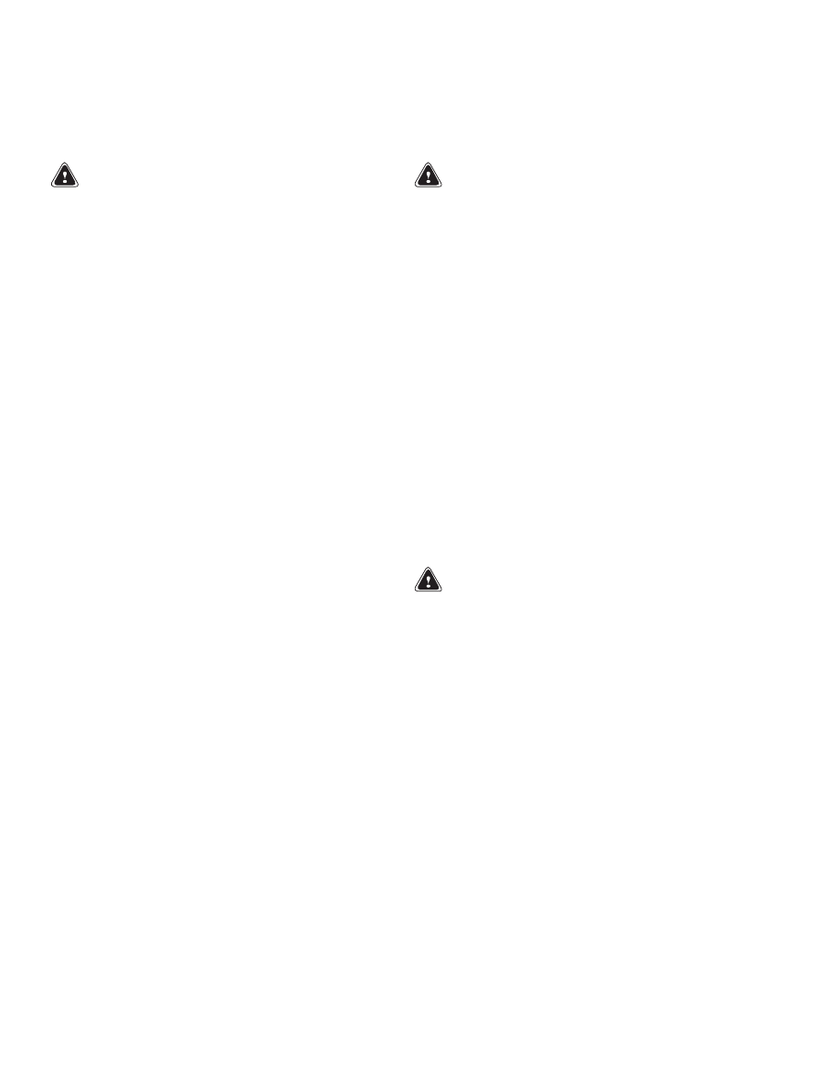
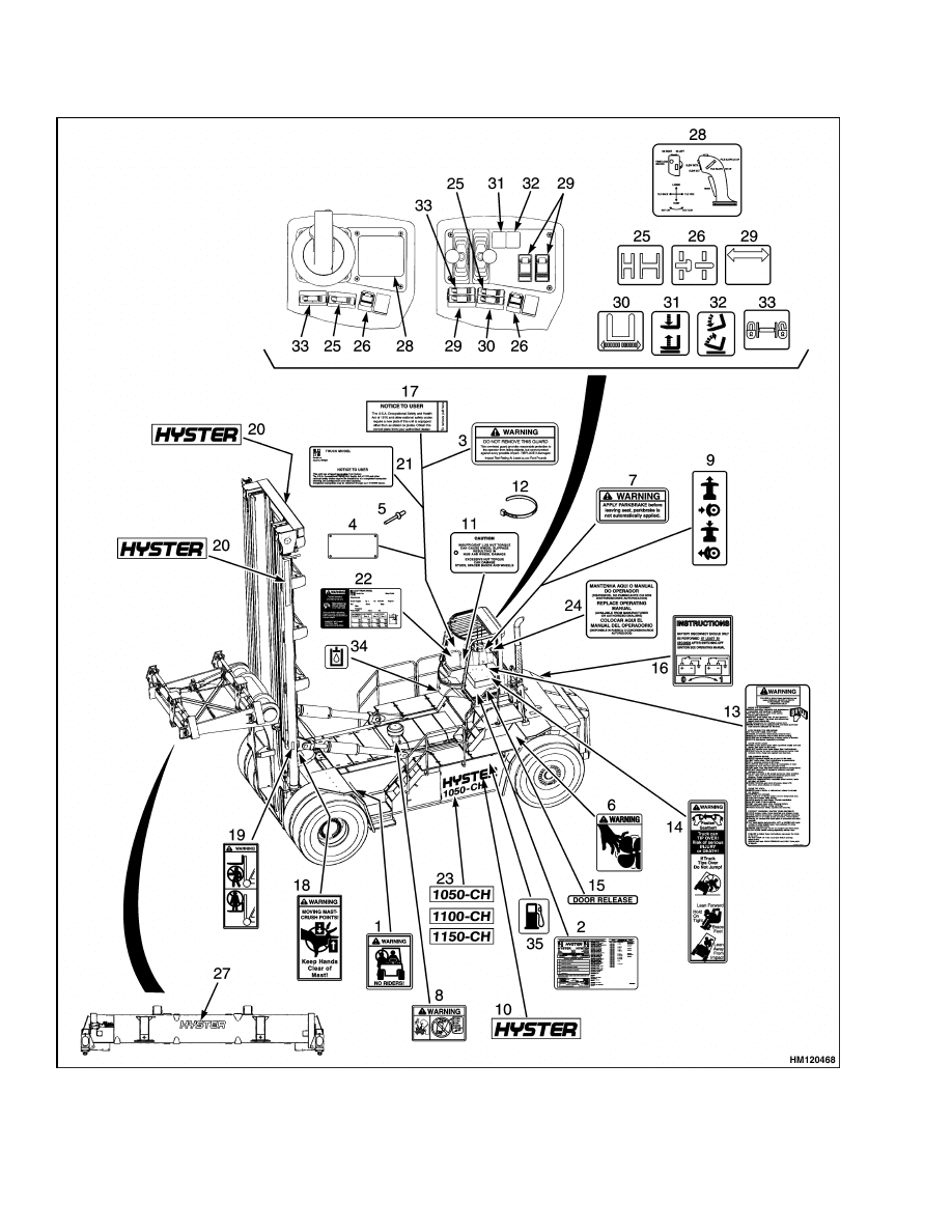
Label Replacement
WARNING
If labels that have warnings or cautions are
damaged, they must be replaced.
See Fig-
ure 13.
If a mast of a different size or an accessory carriage
is installed, the capacity rating can change. Changes
in the size or number of drive tires will change the ca-
pacity rating. See a dealer for Hyster lift trucks for a
replacement nameplate. The nameplate information
is a safety item and must be correct.
1.
Make sure the surface is dry and has no oil or
grease. Do not use solvent on new paint. Clean
the surface of old paint using a cleaning solvent.
2.
Remove the paper from the back of the label. Do
not touch the adhesive surface.
Carefully hold the label in the correct position
above the surface. The label cannot be moved
after it touches the surface. Put the label on the
surface. Make sure all air is removed from under
the label and the corners and edges are tight.
NOTE: If the labels or information plates are miss-
ing or damaged, they must be replaced.
19
Label Replacement
100 SRM 1118
Figure 13. Label Positions
20

100 SRM 1118
Label Replacement
Legend for Figure 13
1.
NO RIDERS LABEL
2.
US PATENTS AND TRADEMARKS LABEL
3.
OVERHEAD GUARD LABEL
4.
NAMEPLATE COVER
5.
PLASTIC RIVET
6.
FAN WARNING LABEL
7.
PARK BRAKE WARNING LABEL
8.
ETHER WARNING LABEL
9.
PARK BRAKE LABEL
10. HYSTER LABEL
11. WHEEL LUG LABEL
12. STRAP CLAMP
13. OPERATOR WARNING LABEL
14. OPERATOR RESTRAINT LABEL
15. DOOR RELEASE LABEL
16. BATTERY DISCONNECT LABEL
17. NOTICE TO USER LABEL
18. MAST WARNING LABEL
19. MAST WARNING LABEL
20. HYSTER MAST LABEL
21. NAMEPLATE (INCOMPLETE)
22. NAMEPLATE
23. MODEL LABEL
24. OPERATOR MANUAL LABEL
25. EXTEND AND RETRACT LABEL
26. TWIST LOCK/UNLOCK LABEL
27. HYSTER CONTAINER HANDLER LABEL
28. JOYSTICK LABEL
29. POWER PILE SLOPE SWITCH LABEL
30. SIDESHIFT SWITCH LABEL
31. HOIST LABEL
32. TILT LABEL
33. HYDRAULIC STOP SWITCH LABEL
34. HYDRAULIC OIL FILL LABEL
35. FUEL FILL LABEL
21

NOTES
____________________________________________________________
____________________________________________________________
____________________________________________________________
____________________________________________________________
____________________________________________________________
____________________________________________________________
____________________________________________________________
____________________________________________________________
____________________________________________________________
____________________________________________________________
____________________________________________________________
____________________________________________________________
____________________________________________________________
____________________________________________________________
____________________________________________________________
____________________________________________________________
____________________________________________________________
____________________________________________________________
____________________________________________________________
____________________________________________________________
22


TECHNICAL PUBLICATIONS
100 SRM 1118
8/04 (7/04) Printed in United Kingdom
Document Outline
- toc
Wyszukiwarka
Podobne podstrony:
910030 1400SRM0047 (08 2004) UK EN
910110 2200SRM0143 (08 2004) UK EN
1578950 2200SRM1119 (08 2004) UK EN
897390 0100SRM0449 (05 2004) UK EN
1554626 0100SRM1073 (06 2004) UK EN
1565181 2000SRM1108 (08 2004) UK EN
897559 0100SRM0545 (06 2004) UK EN
1565183 2200SRM1110 (08 2004) UK EN
897104 0100SRM0322 (05 2004) UK EN
więcej podobnych podstron