FRAME
H1.50-1.75XM (S/H25-35XM)
[C010, D001, D010, E001];
H2.00XMS (S/H40XMS)
[C010, D001, D010, E001]
PART NO. 897559
100 SRM 545

SAFETY PRECAUTIONS
MAINTENANCE AND REPAIR
• When lifting parts or assemblies, make sure all slings, chains, or cables are correctly
fastened, and that the load being lifted is balanced. Make sure the crane, cables, and
chains have the capacity to support the weight of the load.
• Do not lift heavy parts by hand, use a lifting mechanism.
• Wear safety glasses.
• DISCONNECT THE BATTERY CONNECTOR before doing any maintenance or repair
on electric lift trucks. Disconnect the battery ground cable on internal combustion lift
trucks.
• Always use correct blocks to prevent the unit from rolling or falling. See HOW TO PUT
THE LIFT TRUCK ON BLOCKS in the Operating Manual or the Periodic Mainte-
nance section.
• Keep the unit clean and the working area clean and orderly.
• Use the correct tools for the job.
• Keep the tools clean and in good condition.
• Always use HYSTER APPROVED parts when making repairs. Replacement parts
must meet or exceed the specifications of the original equipment manufacturer.
• Make sure all nuts, bolts, snap rings, and other fastening devices are removed before
using force to remove parts.
• Always fasten a DO NOT OPERATE tag to the controls of the unit when making repairs,
or if the unit needs repairs.
• Be sure to follow the WARNING and CAUTION notes in the instructions.
• Gasoline, Liquid Petroleum Gas (LPG), Compressed Natural Gas (CNG), and Diesel fuel
are flammable. Be sure to follow the necessary safety precautions when handling these
fuels and when working on these fuel systems.
• Batteries generate flammable gas when they are being charged. Keep fire and sparks
away from the area. Make sure the area is well ventilated.
NOTE: The following symbols and words indicate safety information in this
manual:
WARNING
Indicates a condition that can cause immediate death or injury!
CAUTION
Indicates a condition that can cause property damage!
Frame
Table of Contents
TABLE OF CONTENTS
General ...............................................................................................................................................................
Description .........................................................................................................................................................
Operator Module Repair ....................................................................................................................................
Remove ...........................................................................................................................................................
Install .............................................................................................................................................................
Hood and Side Covers Repair............................................................................................................................
Remove ...........................................................................................................................................................
Install .............................................................................................................................................................
Overhead Guard Repair ....................................................................................................................................
Remove and Install........................................................................................................................................
LED Backup and Brake Lights, Replace......................................................................................................
Remove.......................................................................................................................................................
Install .........................................................................................................................................................
Counterweight Repair .......................................................................................................................................
Remove ...........................................................................................................................................................
Install .............................................................................................................................................................
Exhaust System Repair .....................................................................................................................................
Muffler, Replace .............................................................................................................................................
Radiator and Cooling System Repair................................................................................................................
Remove ...........................................................................................................................................................
Install .............................................................................................................................................................
Operator Restraint System Repair ...................................................................................................................
Engine Repair ....................................................................................................................................................
Remove (Engine Only)...................................................................................................................................
Remove (Engine and Transmission) .............................................................................................................
Install (Engine Only) .....................................................................................................................................
Install (Engine and Transmission) ...............................................................................................................
Fuel and Hydraulic Tanks Repair.....................................................................................................................
Clean ..............................................................................................................................................................
Steam Method of Cleaning........................................................................................................................
Chemical Solution Method of Cleaning....................................................................................................
Inspect ............................................................................................................................................................
Repair .............................................................................................................................................................
Small Leaks ...............................................................................................................................................
Large Leaks ...............................................................................................................................................
Safety Labels ......................................................................................................................................................
This section is for the following models:
H1.50-1.75XM (S/H25-35XM) [C010, D001, D010, E001];
H2.00XMS (S/H40XMS) [C010, D001, D010, E001]
©2004 HYSTER COMPANY
i

"THE
QUALITY
KEEPERS"
HYSTER
APPROVED
PARTS

100 SRM 545
Operator Module Repair
General
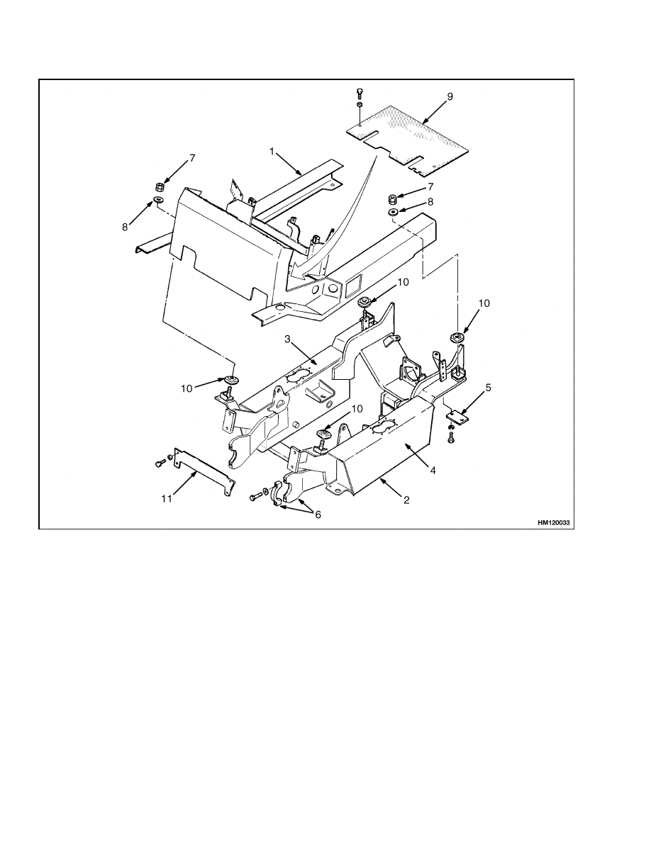
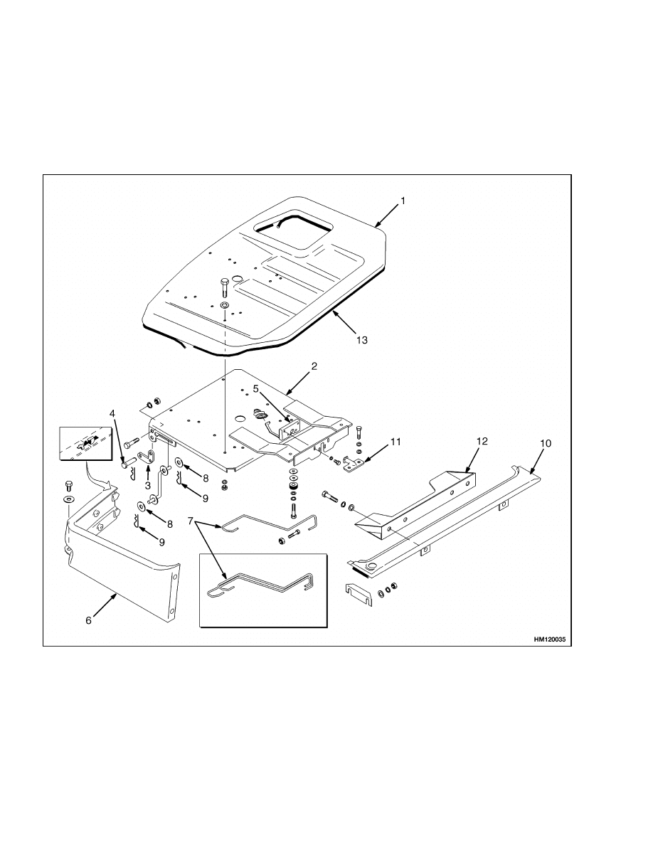
This section has the description of the frame and
some connected parts. See Figure 1. Procedures for
the removal and installation of the counterweight,
hood, overhead guard, and engine (including the
transmission) are under Counterweight Repair,
Hood and Side Covers Repair, Overhead Guard
Repair, and Engine Repair. Checks for the operator
restraint system, repair procedures for the tanks,
and replacement procedures for the safety labels are
also included.
Description
The frame is one weldment and includes the hy-
draulic tank and the fuel tank for gasoline or diesel
fuel. Diesel fuel is not used on the S25-35XM or
S40XMS.
There is a counterweight for each capacity of lift
truck. The counterweights are similar, but are dif-
ferent weights. The muffler is fastened to the frame
inside the counterweight.
An operator module is installed on the frame with
rubber mounts. The overhead guard, steering con-
trols, hydraulic control valve, instrument panel,
hood, and seat are installed on the operator module.
The hood is connected to the operator module with
hinges.
Two torsion springs assist in raising the
hood.
A support rod holds the hood in the open
position.
The floor plates and side covers can be
removed for access to the engine, transmission, and
other components.
Operator Module Repair
REMOVE
WARNING
The lift truck must be put on blocks for some
types of maintenance and repair. The removal
of the following assemblies will cause large
changes in the center of gravity: mast, drive
axle, engine, transmission, and the counter-
weight. When the lift truck is put on blocks,
put additional blocks in the following posi-
tions to maintain stability:
• Before removing the mast and drive axle, put
blocks under the counterweight so the lift
truck cannot fall backward.
• Before removing the counterweight,
put
blocks under the mast assembly so the lift
truck cannot fall forward.
The surface must be solid, even, and level when
the lift truck is put on blocks. Make sure that
any blocks used to support the lift truck are
solid, one-piece units. See the Operating Man-
ual or the section Periodic Maintenance 8000
SRM 531 or Periodic Maintenance 8000 SRM
959
1.
Remove hood and side covers.
2.
Remove three capscrews that hold hydraulic con-
trol valve to mounting bracket.
3.
Remove steering housing and instrument cluster
from cowl. Remove capscrews that hold parking
brake lever to cowl.
NOTE: The module is supported by two different
types of rubber mounts. Mark the mounts for proper
installation.
4.
Remove nuts at mounts for operator module.
5.
Connect lifting device to overhead guard. Over-
head guard and module weigh approximately
385 kg (850 lb). Lift operator module from frame.
See Figure 1.
1
Operator Module Repair
100 SRM 545
1.
OPERATOR MODULE
2.
FRAME
3.
HYDRAULIC TANK
4.
FUEL TANK
5.
STEERING AXLE MOUNT
6.
DRIVE AXLE MOUNT
7.
LOCK NUT ASSEMBLY
8.
WASHER
9.
FLOOR PLATE
10. RUBBER MOUNT
11. PLATE
Figure 1. Frame and Operator Module
INSTALL
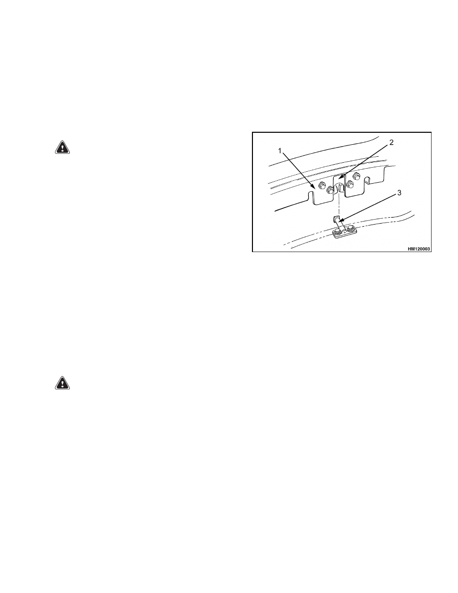
1.
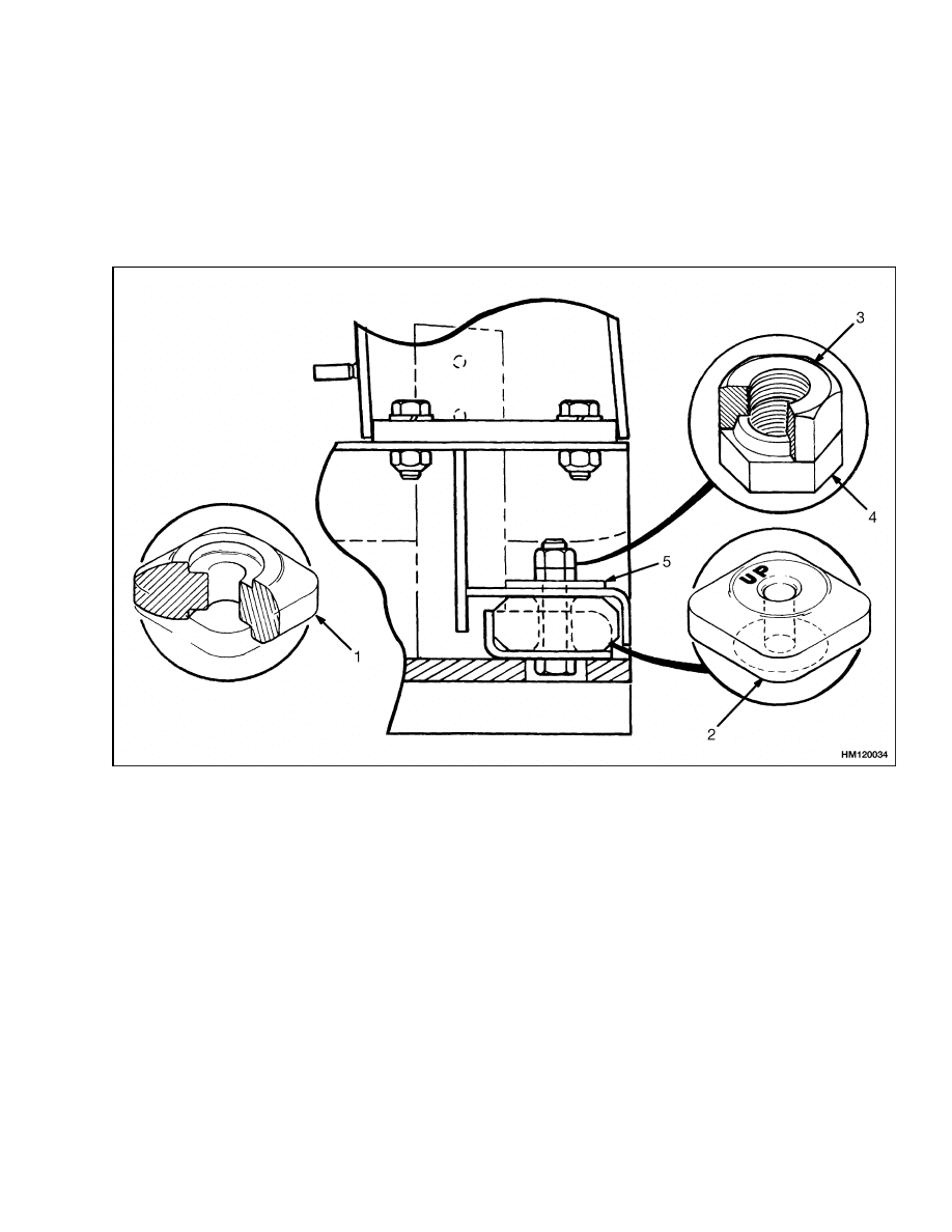
Make sure rubber mounts are properly installed
in frame. See Figure 1. Three mounts with UP
on one side are installed at left rear, left front,
and right front positions of module. Make sure
UP faces upward. See Figure 2. One mount, that
does not have any marking, is installed at right
rear position of module.
2.
Connect lifting device to overhead guard. Over-
head guard and module weigh approximately
385 kg (850 lb). Lift operator module onto frame.
2
100 SRM 545
Operator Module Repair
3.
Install large flat washers and lock nuts. Use fol-
lowing procedure to tighten lock nuts:
a. Tighten bottom lock nut until it just touches
flat washer. Do not compress rubber mount.
b. While holding bottom nut, tighten top nut to
36 N•m (27 lbf ft).
4.
Install hydraulic control valve.
5.
Install hood and side covers.
6.
Install steering controls and parking brake lever.
7.
Install floor plates.
1.
RIGHT REAR RUBBER MOUNT
2.
LEFT REAR AND FRONT RUBBER MOUNT
3.
TOP LOCK NUT
4.
BOTTOM LOCK NUT
5.
WASHER
Figure 2. Module Mounts
3
Hood and Side Covers Repair
100 SRM 545
Hood and Side Covers Repair
REMOVE
NOTE: The combined weight of the hood and seat is
approximately 45 kg (100 lb). Have a helper or use a
lifting device to remove the hood and seat.
1.
Raise hood and hold hood so it does not fall. Dis-
connect torsion springs and support rod at hood.
See Figure 3.
NOTE: ON LATER MODELS, HINGE IS NOT A SERVICEABLE PART. IT IS WELDED ONTO SEAT PAN.
1.
HOOD
2.
SEAT PAN
3.
HINGE
4.
PIVOT PIN
5.
HOOD LATCH
6.
SIDE COVER
7.
TORSION SPRING
8.
WASHER
9.
PIN
10. COVER
11. LATCH STRIKER
12. BRACKET
13. SEAL
Figure 3. Hood and Side Covers
4
100 SRM 545
Overhead Guard Repair
2.
Remove rod end pins and pivot pins from hood
hinges. Remove hood.
INSTALL
1.
Install hood in position on lift truck. See Fig-
ure 3. Install pivot pins and rod end pins at hood
hinges. Connect torsion springs and support rod
to hood.
WARNING
The hood, the hood latch, and the latch striker
must be correctly adjusted for the operator re-
straint system to function correctly.
2.
Adjust hood latch as follows:
a. Install hood latch in lowest slot position on
frame of hood. Tighten capscrews so hood
latch can still move when hood is closed.
b. Install latch striker. Check that latch striker
is in center of jaws of hood latch when hood
closes.
c.
Carefully close hood to fully closed position.
Hood latch has two positions. Hood is fully
closed after two clicks of latch.
d. Push hood down until it just touches rubber
bumpers. Make sure latch striker is still in
center of hood latch. Open hood and tighten
capscrews for latch.
e.
Check operation of hood latch. See Figure 4.
Have operator sit in seat. Make sure hood is
fully closed (two clicks). Also check that hood
touches rubber bumpers. If necessary, repeat
Step d.
1.
HOOD FRAME
2.
HOOD LATCH
3.
LATCH STRIKER
Figure 4. Hood Latch Check
Overhead Guard Repair
REMOVE AND INSTALL
WARNING
Do not operate the lift truck without the over-
head guard correctly fastened to the lift truck.
Changes that are made by welding, or by
drilling holes that are too big or in the wrong
location, can reduce the strength of the over-
head guard. See the instructions for Changes
to the Overhead Guard in the section Periodic
Maintenance 8000 SRM 531 or Periodic Main-
tenance 8000 SRM 959.
NOTE: The air inlet for the gasoline/LPG air filter is
installed on the left-hand leg of the overhead guard.
The air inlet for the diesel air filter is installed on the
right-hand leg of the overhead guard. Make sure the
grille is installed with the louvers pointed downward.
1.
Connect crane or lifting device to overhead guard
for removal or installation.
2.
Disconnect air intake at overhead guard leg.
Disconnect any wires between frame and over-
head guard.
When overhead guard is lifted
from frame, make sure electric wires are moved
through holes in frame so they are not damaged.
3.
Remove two bolts at each front corner and two
bolts and lock nuts at each rear corner of over-
head guard. During installation, tighten bolts to
65 N•m (48 lbf ft).
5
Counterweight Repair
100 SRM 545
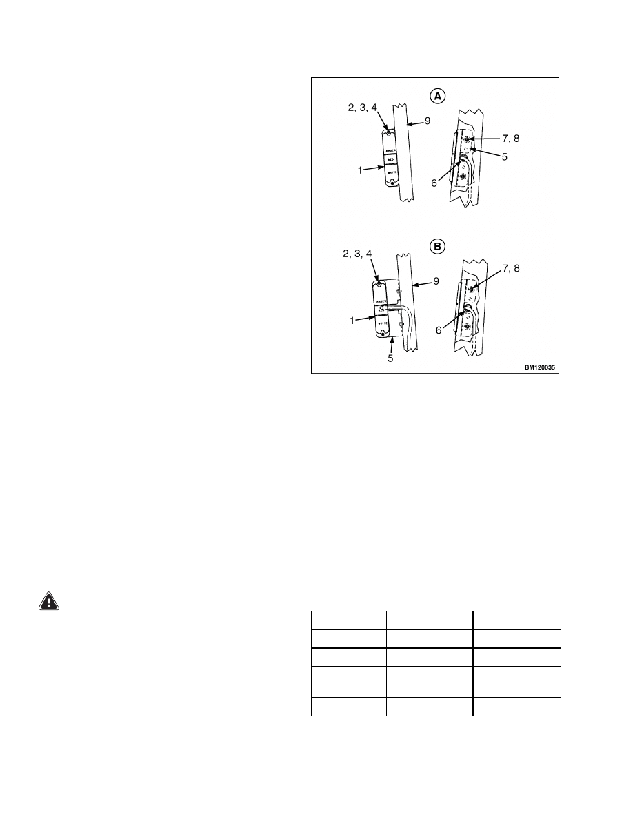
LED BACKUP AND BRAKE LIGHTS,
REPLACE
NOTE: Newer models of lift trucks are equipped
with LED (Light Emitting Diode) backup and brake
tail lights. These light assemblies are non-repairable
and must be replaced as a complete unit. See the
Parts Manual for replacement LED lights.
Remove
1.
Disconnect negative terminal of battery and re-
move the key.
2.
Disconnect the LED light from the chassis light
harness.
3.
Remove LED light assembly and harness from
mounting bracket. See Figure 5.
4.
If the LED mounting bracket must be removed
from the overhead guard leg, remove the plug,
screw and bracket from the overhead guard leg.
Install
1.
If the mounting bracket was removed, install it
onto the overhead guard leg. Insert the plug and
screw to attach mounting bracket to overhead
guard leg. See Figure 5.
2.
Install the LED light assembly and harness on
the mounting bracket.
3.
Connect the LED light to the chassis light har-
ness.
4.
Connect negative terminal of battery and close
the hood.
A. LED ASSEMBLY WITH STANDARD EXHAUST
B. LED ASSEMBLY WITH OVERHEAD EXHAUST
1.
LED LIGHT
2.
SCREW
3.
WASHER
4.
LOCKNUT
5.
MOUNTING BRACKET
6.
GROMMET
7.
PLUG
8.
SCREW
9.
OVERHEAD GUARD LEG
Figure 5. LED Backup and Brake Lights
Assembly
Counterweight Repair
WARNING
The counterweight is heavy. Make sure the eye-
bolt and lifting devices have enough capacity
to lift the weight. The approximate weights of
the counterweight castings are shown in Ta-
ble 1.
Do not operate the lift truck if the capscrews
for the counterweight are not installed. When
the capscrews are removed, the counterweight
can fall from the lift truck.
Table 1. Weight of Counterweights
Model
kg
lb
H25XM
668 to 682
1473 to 1504
S25XM
634 to 646
1398 to 1424
H1.50XM
(H30XM)
824 to 840
1817 to 1852
S30XM
807 to 823
1779 to 1814
6
100 SRM 545
Counterweight Repair
Table 1. Weight of Counterweights (Continued)
Model
kg
lb
H1.75XM
(H35XM)
997 to 1017
2198 to 2242
S35XM
990 to 1010
2183 to 2227
H2.00XMS
(H40XMS)
1167 to 1191
2573 to 2626
S40XMS
1179 to 1203
2599 to 2652
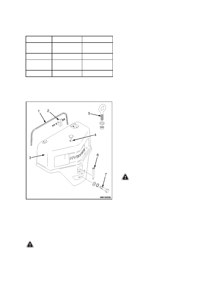
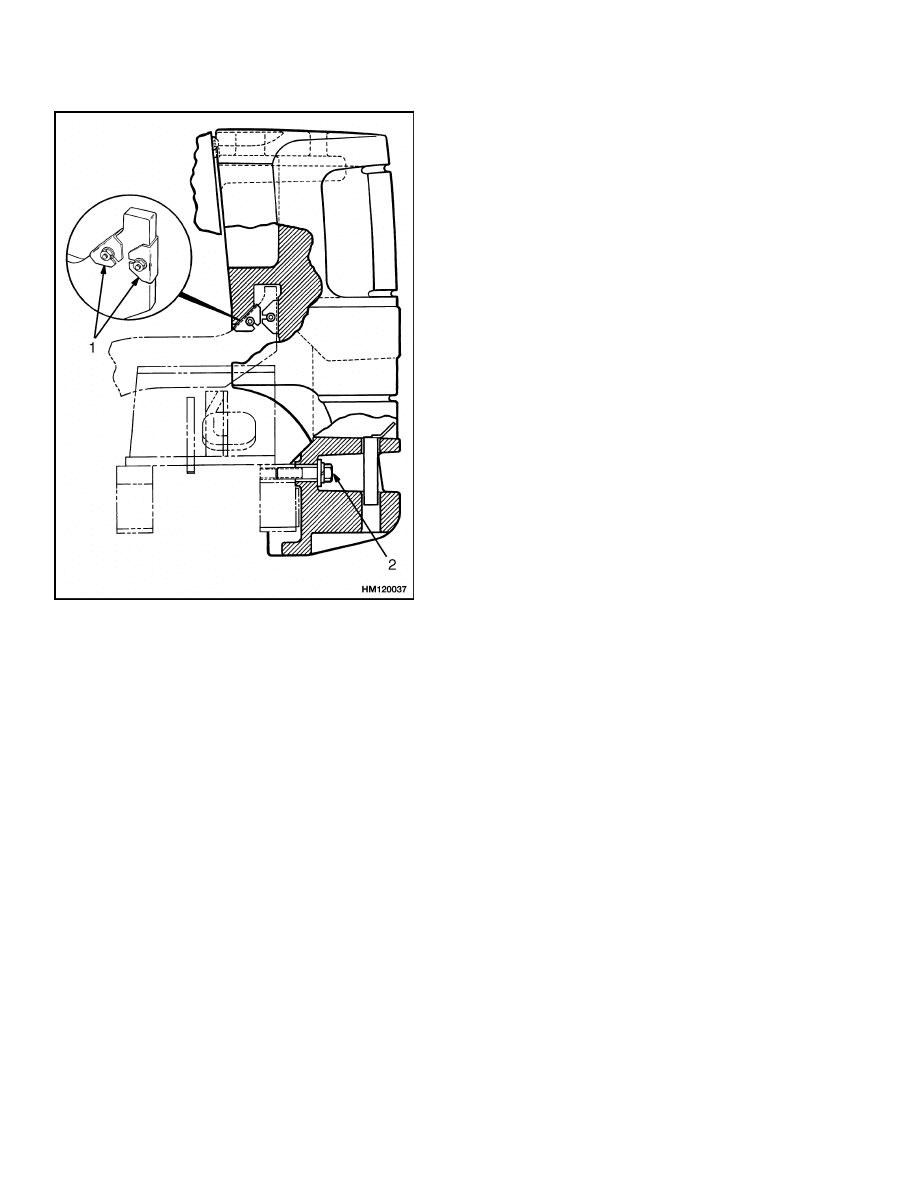
The counterweight is held in position on the frame by
two hooks that are part of the frame. Two M24 × 3
capscrews hold the counterweight to the lower part
of the frame. See Figure 6 and Figure 7.
1.
SEAL
2.
SPACER
3.
COUNTERWEIGHT
4.
HOLE FOR
EYEBOLT
5.
EYEBOLT
6.
TOW PIN
7.
CAPSCREW
Figure 6. Counterweight
REMOVE
WARNING
LPG can cause an explosion.
Do not cause
sparks or permit flammable material near the
LPG system. LPG fuel systems can be discon-
nected indoors only if the lift truck is at least
8 m (26 ft) from any open flame, motor vehicles,
electrical equipment, or ignition source.
Close the shutoff valve on the LPG tank before
any part of the engine fuel system is discon-
nected. Run the engine until the fuel in the sys-
tem is used and the engine stops.
If the engine will not run, close the shutoff
valve on the LPG tank. Loosen the fitting on
the supply hose from the LPG tank where it
enters the filter unit. Permit the pressure in
the fuel system to decrease slowly. Fuel leav-
ing the fitting is cold. Use a cloth to protect
your hands from the cold fitting.
NOTE: LPG tanks can be removed and replaced in-
doors only if the lift truck is at least 8 m (26 ft) from
any flame or ignition source.
1.
If lift truck has LPG fuel system, remove LPG
tank and bracket so that counterweight can be
removed.
Use following procedure to remove
LPG tank:
a. Move lift truck to area where tanks are
changed.
b. Turn shutoff valve clockwise until valve is
completely closed.
c.
Run engine until it stops, then turn ignition
switch to OFF position.
WARNING
Fuel leaving the fitting is cold. Use a cloth to
protect your hands from the cold fitting.
If engine will not run, close shutoff valve on
LPG tank.
Loosen fitting on supply hose
from LPG tank where it enters filter unit.
Allow pressure in fuel system to decrease
slowly.
d. Disconnect quick-disconnect fitting.
e.
Release LPG tank latch and remove tank
from bracket.
2.
If overhead exhaust is installed, remove it as
shown in Figure 8 and Figure 9.
7
Exhaust System Repair
100 SRM 545
1.
SPACER
2.
CAPSCREW
Figure 7. Counterweight Installation
3.
Install lifting eye in lifting hole of counterweight.
See Figure 6. Connect crane to lifting eye and
raise crane until it holds some weight of coun-
terweight. Remove capscrew that holds counter-
weight to frame. Use crane to lift counterweight
from lift truck. Put counterweight on floor so it
is stable and will not fall over.
INSTALL
1.
Install spacers on mounts. See Figure 7. When
counterweight is installed, make sure hooks on
frame fully engage counterweight so it is aligned
with frame. Use spacers to obtain a gap of 7.5
to 10.5 mm (0.30 to 0.41 in.) between counter-
weight and overhead guard leg. Tighten M24 × 3
capscrews to 555 N•m (409 lbf ft).
2.
If lift truck has LPG fuel system, install bracket
for LPG tank. Use following procedure to install
LPG tank:
a. Before LPG tank is installed on lift truck,
make sure tank has fuel in it. Check oper-
ation of fuel gauge. Look at fuel gauge and
move tank. If gauge needle does not move,
new tank must be installed.
b. Put tank in tank bracket. Make sure tank is
aligned with alignment pin.
c.
Close latch.
d. Connect quick-disconnect fitting to shutoff
valve on tank.
Use your hand to tighten
fitting.
Do not open shutoff valve until
quick-disconnect fitting is completely tight-
ened. Turn shutoff valve counterclockwise to
open valve.
e.
Inspect fuel system for leaks when shutoff
valve is open. Strong odor or frost on surface
of tank, valves, or fittings indicates leakage.
3.
If lift truck has overhead exhaust, install it as
shown in Figure 8 and Figure 9.
Exhaust System Repair
The muffler is installed inside the cavity of the coun-
terweight. A short exhaust pipe sends the exhaust
gases out of the lift truck through the grille in the
counterweight.
The lift truck may have an overhead exhaust system.
The exhaust pipe is fastened to the top of the coun-
terweight.
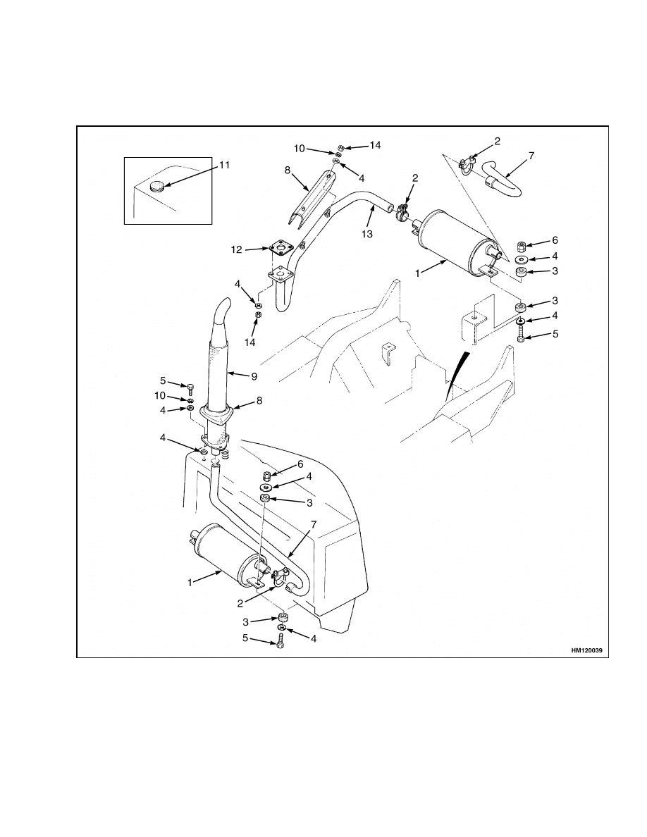
MUFFLER, REPLACE
The counterweight must be removed to replace the
muffler. When replacing parts of the exhaust system,
see Figure 8, Figure 9, or Figure 10. When connect-
ing the exhaust pipe to the engine, do the following:
• On units with gasoline or LPG engine, tighten ex-
haust pipe nuts to 16 to 23 N•m (12 to 17 lbf ft).
8
100 SRM 545
Exhaust System Repair
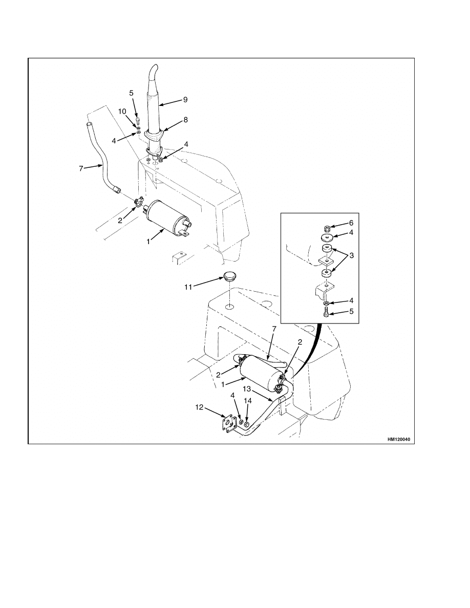
• On units with diesel engine, tighten exhaust pipe
nuts to 32 to 47 N•m (24 to 35 lbf ft).
• On units with overhead exhaust, tighten capscrews
that hold vertical pipe to counterweight to 15 to
18 N•m (11 to 13 lbf ft). Install cover.
1.
MUFFLER
2.
CLAMP
3.
RUBBER CUSHION
4.
WASHER
5.
CAPSCREW
6.
LOCK NUT ASSEMBLY
7.
TAILPIPE
8.
COVER
9.
VERTICAL PIPE
10. LOCKWASHER
11. RUBBER CAP
12. GASKET
13. EXHAUST PIPE
14. NUT
Figure 8. Gas and LPG Exhaust System
9
Exhaust System Repair
100 SRM 545
NOTE: S25-35XM AND S40XMS USE COUNTERWEIGHT EXHAUST ONLY.
1.
MUFFLER
2.
CLAMP
3.
RUBBER CUSHION
4.
WASHER
5.
CAPSCREW
6.
LOCK NUT ASSEMBLY
7.
TAILPIPE
8.
COVER
9.
VERTICAL PIPE
10. LOCKWASHER
11. RUBBER CAP
12. GASKET
13. EXHAUST PIPE
14. NUT
Figure 9. Diesel Exhaust System
10
100 SRM 545
Exhaust System Repair
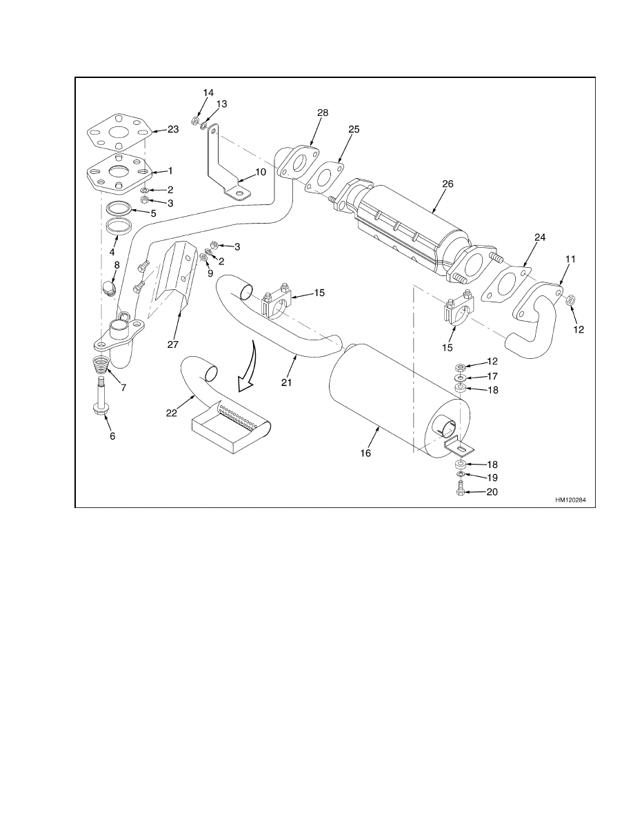
1.
ADAPTER
2.
LOCKWASHER
3.
NUT
4.
SPACER
5.
SEAL
6.
CAPSCREW
7.
SPRING
8.
PLUG (RAW GAS CHECK PORT)
9.
WASHER
10. BRACKET
11. EXHAUST PIPE
12. NUT
13. WASHER
14. NUT
15. CLAMP
16. MUFFLER
17. RUBBER WASHER
18. CUSHION
19. WASHER
20. CAPSCREW
21. TAILPIPE
22. TAILPIPE (LPS)
23. GASKET
24. GASKET
25. GASKET
26. CATALYTIC CONVERTER
27. COVER
28. EXHAUST PIPE
Figure 10. Low-Emissions Exhaust System (LPG)
11
Radiator and Cooling System Repair
100 SRM 545
Radiator and Cooling System Repair
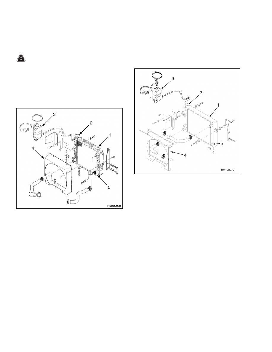
REMOVE
WARNING
DO NOT remove the radiator cap while it is hot.
Hot coolant and steam can cause burns. Make
sure the label is on the radiator cap. See Fig-
ure 11.
1.
Open drain valve and drain coolant from radi-
ator. Remove bottom radiator hose and drain
coolant from engine. See Figure 11 or Figure 12.
1.
RADIATOR
2.
RADIATOR CAP
3.
AUXILIARY COOLANT RESERVOIR
4.
SHROUD
5.
DRAIN VALVE
Figure 11. Cooling System (Earlier Models)
2.
Remove capscrews that fasten fan to hub. Re-
move capscrews that hold fan shroud to radiator.
Remove both fan and fan shroud.
3.
Disconnect top coolant hose at radiator. Discon-
nect lines to oil cooler inside of radiator. Put caps
on open lines and ports. Remove capscrews that
hold radiator to frame. Remove radiator.
1.
RADIATOR
2.
RADIATOR CAP
3.
AUXILIARY COOLANT RESERVOIR
4.
SHROUD
5.
DRAIN VALVE
Figure 12. Cooling System (Later Models)
INSTALL
1.
Install radiator. Install fan and fan shroud in
position on radiator. Install capscrews that hold
fan shroud. Install capscrews that fasten fan to
hub.
2.
Connect upper coolant hoses at radiator. Connect
lines for transmission oil to oil cooler in radiator.
12
100 SRM 545
Operator Restraint System Repair
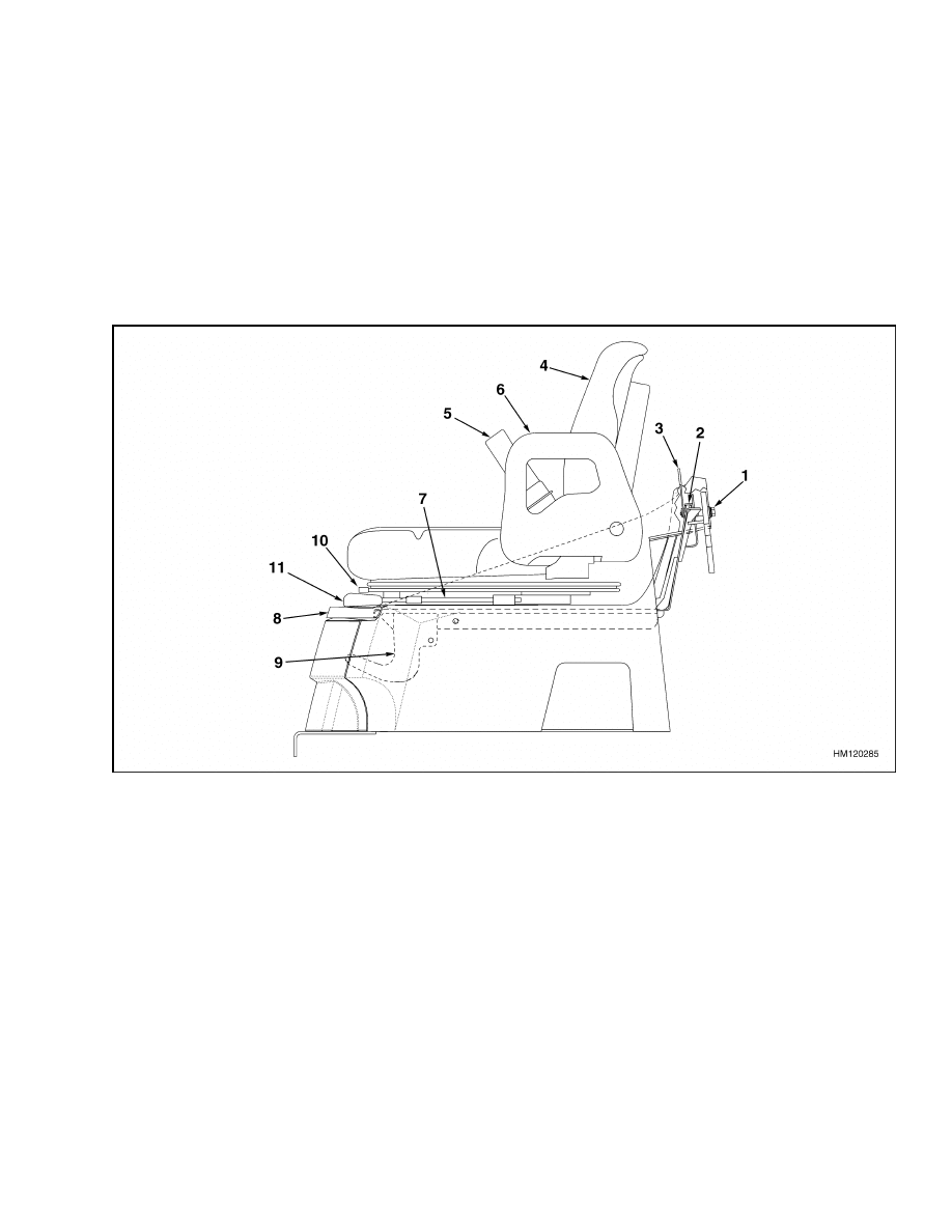
Operator Restraint System Repair
The seat belt, hip restraint, seat and mount, hood,
and latch are all part of the operator restraint sys-
tem. Each item must be checked to make sure it is
fastened correctly, functions correctly, and is in good
condition. See Figure 13.
The end of the seat belt must fasten correctly in the
latch. Make sure the seat belt pulls from the re-
tractor assembly and retracts smoothly. The seat
belt must be in good condition. A seat belt that is
damaged or worn will not give protection when it is
needed. If the seat belt cannot be pulled from the re-
tractor assembly, replace the seat belt assembly.
Adjust the hood, the hood latch, and the latch striker
when any of the parts of the operator restraint sys-
tem are installed or replaced. See Hood and Side
Covers Repair for the adjustment procedures.
1.
LATCH STRIKER
2.
HOOD LATCH
3.
LATCH LEVER
4.
SEAT
5.
SEAT BELT LATCH
6.
HIP RESTRAINT
7.
SEAT RAIL
8.
HOOD
9.
HINGE
10. SUPPORT ROD
11. COVER
Figure 13. Hood and Seat Check
13
Engine Repair
100 SRM 545
Engine Repair
WARNING
Always disconnect the cables at the battery be-
fore you make repairs to the engine. Discon-
nect the cable at the negative terminal first.
The engine can be removed with or without the trans-
mission.
REMOVE (ENGINE ONLY)
1.
Remove floor plates. Remove hood and side cov-
ers. Remove air filter and battery. Remove radi-
ator.
2.
Disconnect throttle linkage. Disconnect exhaust
system.
3.
Disconnect wires and wiring harnesses at en-
gine. Disconnect and plug fuel lines at engine.
4.
Disconnect pump drive at engine.
WARNING
The engine is heavy. Make sure that any lifting
device has enough capacity to lift the engine.
The engine can weigh approximately 340 kg
(750 lb).
5.
Connect lifting device to engine. Put block under
transmission housing for support.
6.
Remove capscrews that hold torque converter
housing to flywheel housing. Remove capscrews
that hold drive plate to torque converter.
7.
Remove nuts and bolts from engine mounts. Use
lifting device to carefully move engine away from
torque converter. Make sure all hoses, wires, and
cables are disconnected from engine, then lift en-
gine from frame.
REMOVE (ENGINE AND TRANSMISSION)
1.
Perform Step 1 through Step 4 in Remove (En-
gine Only) procedure.
2.
Disconnect oil cooler lines at transmission. Plug
oil cooler hoses and put caps on fittings.
3.
Disconnect all wires and harnesses from trans-
mission.
4.
Drain differential housing. Remove axle shafts.
WARNING
The engine and transmission are heavy. Make
sure that any lifting device has enough capac-
ity to lift the engine. The engine and transmis-
sion can weigh approximately 680 kg (1500 lb).
5.
Connect lifting device to engine. Remove nuts
and bolts from engine mounts.
Remove cap-
screws that hold transmission to differential
housing. Use lifting device to carefully lift en-
gine and transmission from frame.
INSTALL (ENGINE ONLY)
WARNING
The engine is heavy. Make sure that any lifting
device has enough capacity to lift the engine.
The engine can weigh approximately 340 kg
(750 lb).
1.
Make sure torque converter is installed in trans-
mission and drive plate is on flywheel. Connect
lifting device to engine. Lift engine into frame.
Carefully align drive plate with transmission.
See the section Single-Speed Powershift
Transmission, Description, Operation, and
Repairs 1300 SRM 543.
2.
Make sure pilot on torque converter is in hole in
flywheel. Install capscrews that hold torque con-
verter housing to flywheel housing. Install cap-
screws that hold drive plate to torque converter.
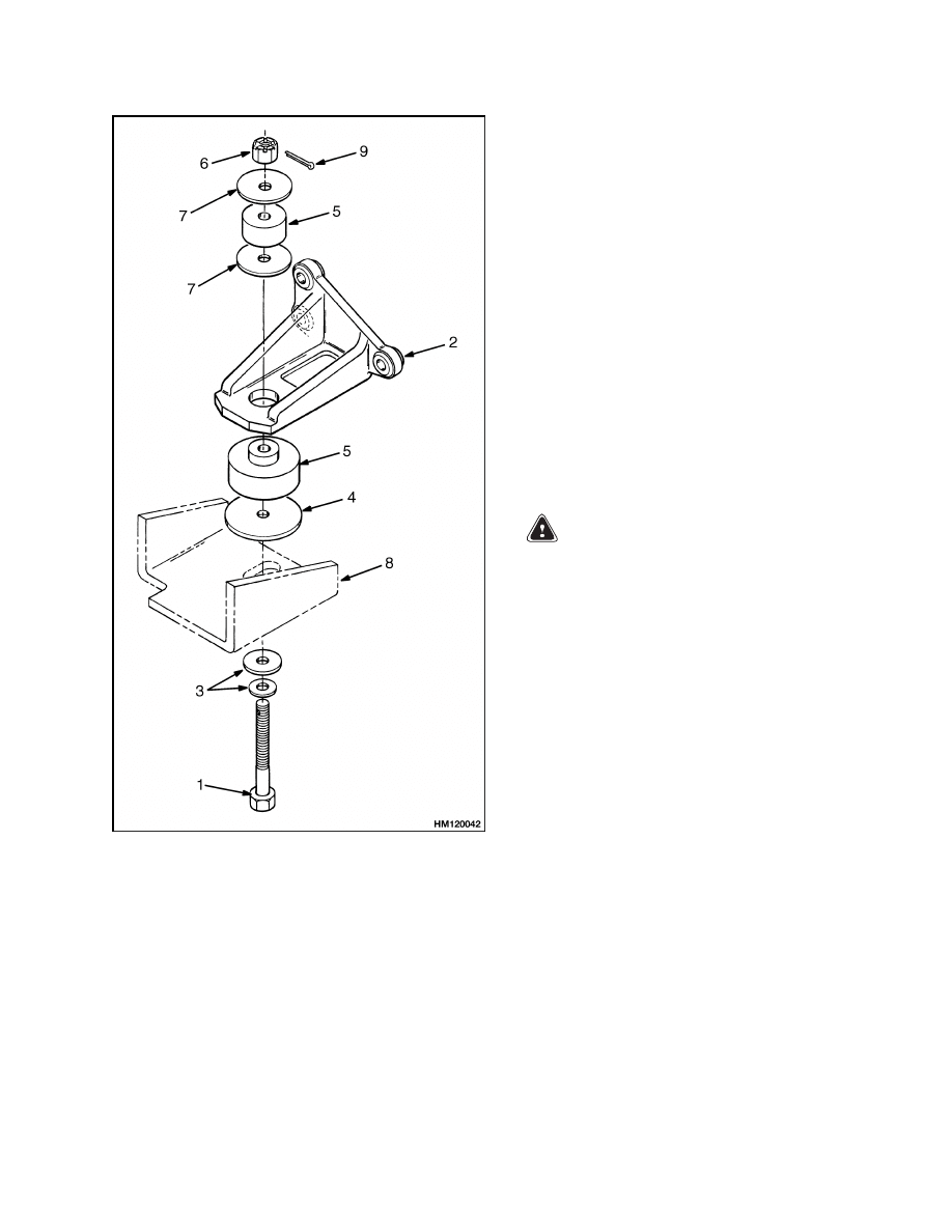
3.
Install and tighten nuts and bolts for engine
mounts. Install parts as shown in Figure 14.
14
100 SRM 545
Engine Repair
1.
BOLT
2.
ENGINE MOUNT
3.
FLAT WASHER
4.
SPACER
5.
RUBBER MOUNT
6.
NUT
7.
CUSHION
WASHER
8.
FRAME MOUNT
9.
PIN
Figure 14. Engine Mounts
4.
Install radiator and connect coolant hoses and
lines from the transmission.
5.
Connect wires and wiring harnesses at engine.
Connect fuel lines at engine.
6.
Connect throttle linkage. Connect exhaust sys-
tem. Install air filter assembly.
7.
Install battery. Install side covers and hood.
8.
Connect pump drive shaft. Tighten capscrews to
21 to 25 N•m (15 to 18 lbf ft).
9.
Check all fluid levels as described in Periodic
Maintenance section for your lift truck.
INSTALL (ENGINE AND TRANSMISSION)
1.
Put lift truck on blocks so you have access under
the lift truck. See procedure in Periodic Main-
tenance section for your lift truck.
WARNING
The engine and transmission are heavy. Make
sure that any lifting device has enough capac-
ity to lift the weight. The engine and transmis-
sion can weigh approximately 680 kg (1500 lb).
2.
Connect lifting device to engine. Lift engine and
transmission into frame.
Install transmission
into differential. Install capscrews that attach
transmission to differential housing.
3.
Install and tighten nuts and bolts for engine
mounts. Install parts as shown in Figure 14.
4.
Connect cooler lines, wires, and harnesses.
5.
Perform Step 4 through Step 9 in Install (Engine
Only) procedure.
15

Fuel and Hydraulic Tanks Repair
100 SRM 545
Fuel and Hydraulic Tanks Repair
CLEAN
Steam Method of Cleaning
When cleaning with steam, use a hose with a mini-
mum diameter of 19 mm (0.75 in.). Control the pres-
sure of the steam by a valve installed at the nozzle of
the hose. If a metal nozzle is used, it must be made of
a material that does not make sparks. Make an elec-
trical connection between the nozzle and the tank.
Connect a ground wire to the tank to prevent static
electricity.
1.
Remove all parts from tank. Install drain plug.
2.
Fill tank 1/4 full with solution of water and
sodium bicarbonate or sodium carbonate. Mix
0.5 kg (1 lb) per 4 liter (1 gal) of water.
WARNING
Compressed air can move particles so that they
cause injury to the user or to other personnel.
Make sure that the path of the compressed air
is away from all personnel.
Wear protective
goggles or a face shield to prevent injury to the
eyes.
3.
Use compressed air to mix solution in tank.
Make sure all surfaces on inside of tank are
flushed with solution, then drain tank.
4.
Put steam into tank until tank does not have
odors and metal is hot. Steam vapors must come
from all openings.
5.
Flush inside of tank with boiling water. Make
sure all loose material is removed from inside of
tank.
6.
Inspect inside of tank. If it is not clean, repeat
Step 4 and Step 5 and make another inspection.
When making inspections, use light that is ap-
proved for locations with flammable vapors.
7.
Put plugs in all openings in tank. Wait 15 min-
utes, then remove inlet and outlet plugs. Use
special indicator for gas vapors to check tank
for flammable vapors. If amount of flammable
vapors is above lower flammable limit, repeat
cleaning procedure.
Chemical Solution Method of Cleaning
WARNING
When cleaning the tank, do not use solutions
that make dangerous gases at normal temper-
atures or when heated. Wear eye and face pro-
tection. Protect the body from burns.
1.
Mix solution of water and trisodium phosphate
or cleaning compound with alkali base. Follow
manufacturer’s instructions.
WARNING
Compressed air can move particles so that they
cause injury to the user or to other personnel.
Make sure that the path of the compressed air
is away from all personnel.
Wear protective
goggles or a face shield to prevent injury to the
eyes.
2.
Fill tank with cleaning solution. Use compressed
air to mix solution in tank.
3.
Drain tank. Flush inside of tank with boiling
water. Make sure all cleaning compound is re-
moved.
4.
Inspect inside of tank. If tank is not clean, repeat
Step 1 through Step 3. Make another inspection
of tank. When making inspections, use light that
is approved for locations with flammable vapors.
5.
Use special indicator for gas vapors to check tank
for flammable vapors. If amount of flammable
vapors is above lower flammable limit, repeat
cleaning procedure.
INSPECT
WARNING
Do not use tools that can make sparks, heat, or
static electricity. The vapors in the tank can
cause an explosion.
Make a visual inspection of all sides of the tank. In-
spect the welds for cracks and leakage. Check for
wet areas, accumulation of dirt, and loose or miss-
ing paint caused by leakage. Areas of the tank that
are not easily seen can be checked with an inspection
mirror and a light that is approved for locations with
flammable vapors.
16
100 SRM 545
Safety Labels
REPAIR
Small Leaks
1.
Use steam to clean area around leak. Remove all
paint and dirt around leak.
2.
Apply Loctite
®
290 to leak.
Follow manufac-
turer’s instructions.
Large Leaks
WARNING
Special procedures must be followed when
large leaks or other repairs need welding or
cutting. All work must be done by authorized
personnel. If the tank is cleaned inside of a
building, make sure there is enough ventila-
tion. See the following manuals for additional
information:
• Safe Practices for Welding and Cutting Con-
tainers That Have Held Combustibles by the
American Welding Society, F4.1 - 1999.
• Safety in Welding and Cutting, American Na-
tional Standard, AWS Z 49.1 - 1999.
1.
Use cleaning procedure to clean and prepare
tank for repairs.
2.
If nitrogen gas or carbon dioxide gas is available,
prepare tank for welding using these gases. If
these gases are not available, fill tank with wa-
ter to just below point where work will be done.
Make sure space above water level has vent.
3.
Contact your dealer for Hyster lift trucks for
welding instructions.
Use acceptable welding
practices to repair tank.
Safety Labels
WARNING
Safety labels are installed on the lift truck to
give information about operation and possible
hazards. It is important that all safety labels
are installed on the lift truck and can be read.
DO NOT add to or modify the lift truck. Any
change to the lift truck, the tires, or its equip-
ment can change the lifting capacity. The lift
truck must be rated as equipped and the name-
plate must show the new capacity rating. Con-
tact your dealer for Hyster lift trucks for a re-
placement nameplate.
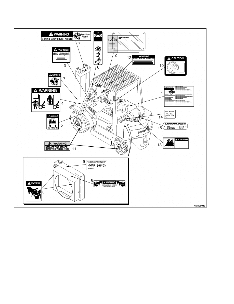
If a label must be replaced, use the following proce-
dure to install a new label: See Figure 15 and Fig-
ure 16.
WARNING
Cleaning solvents can be flammable and toxic
and can cause skin irritation.
When using
cleaning solvents, always follow the recom-
mendations of the manufacturer.
1.
Make sure surface is dry and has no oil or grease.
Do not use solvent on new paint. Clean surface
of old paint with cleaning solvent.
2.
Remove paper from back of label. Do not touch
adhesive surface.
3.
Carefully hold label in correct position above sur-
face. (Label cannot be moved after it touches sur-
face.) Put label on surface. Make sure all air is
removed from under label and corners and edges
are tight.
17
Safety Labels
100 SRM 545
NOTE: SEE THE PARTS MANUAL FOR PART NUMBERS OF LABELS.
1.
WARNING, OPERATION
2.
NAMEPLATE
3.
WARNING FOR PARKING BRAKE
4.
NO ONE ON OR UNDER FORKS
5.
NO RIDERS
6.
TIPOVER WARNING
7.
MAST WARNING
8.
FAN WARNING
9.
ANTIFREEZE REQUIREMENT
10. ETHER WARNING (NOT USED ON ALL UNITS)
11. TWO-PIECE WHEEL WARNING
12. OVERHEAD GUARD WARNING
13. FLAMMABLE LPG (NOT USED ON ALL UNITS)
14. LPG NAMEPLATE (NOT USED ON ALL UNITS)
15. LPG IDENTIFIER (NOT USED ON ALL UNITS)
Figure 15. Label Positions for H1.50-1.75XM, H2.00XMS (H25-35XM, H40XMS)
18
100 SRM 545
Safety Labels
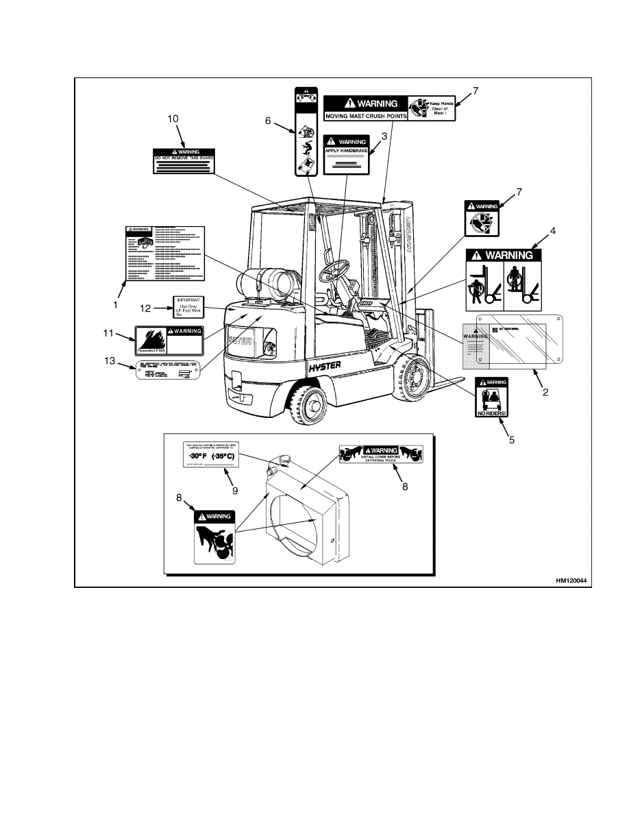
NOTE: SEE THE PARTS MANUAL FOR PART NUMBERS OF LABELS.
1.
OPERATION WARNING
2.
NAMEPLATE
3.
WARNING FOR PARKING BRAKE
4.
NO ONE ON OR UNDER FORKS
5.
NO RIDERS
6.
TIPOVER WARNING
7.
MAST WARNING
8.
FAN WARNING
9.
ANTIFREEZE REQUIREMENT
10. OVERHEAD GUARD WARNING
11. FLAMMABLE LPG (NOT USED ON ALL UNITS)
12. LPG NAMEPLATE (NOT USED ON ALL UNITS)
13. LPG IDENTIFIER (NOT USED ON ALL UNITS)
Figure 16. Label Positions for S25-35XM, S40XMS
19

NOTES
____________________________________________________________
____________________________________________________________
____________________________________________________________
____________________________________________________________
____________________________________________________________
____________________________________________________________
____________________________________________________________
____________________________________________________________
____________________________________________________________
____________________________________________________________
____________________________________________________________
____________________________________________________________
____________________________________________________________
____________________________________________________________
____________________________________________________________
____________________________________________________________
____________________________________________________________
____________________________________________________________
____________________________________________________________
____________________________________________________________
20


TECHNICAL PUBLICATIONS
100 SRM 545
6/04 (2/01)(11/94)(9/93) Printed in United Kingdom
Document Outline
- toc
- Frame
- Safety Precautions Maintenance and Repair
- General
- Description
- Operator Module Repair
- Hood and Side Covers Repair
- Overhead Guard Repair
- Counterweight Repair
- Exhaust System Repair
- Radiator and Cooling System Repair
- Operator Restraint System Repair
- Engine Repair
- Fuel and Hydraulic Tanks Repair
- Safety Labels
- tables
Wyszukiwarka
Podobne podstrony:
1554626 0100SRM1073 (06 2004) UK EN
1554635 8000SRM1079 (06 2004) UK EN
1565454 8000SRM1113 (06 2004) UK EN
1554632 2000SRM1086 (06 2004) UK EN
1566270 0100SRM1118 (08 2004) UK EN
897494 1900SRM0513 (06 2004) UK EN
897390 0100SRM0449 (05 2004) UK EN
1554630 1900SRM1077 (06 2004) UK EN
897880 1400SRM0618 (06 2004) UK EN
897881 1600SRM0619 (06 2004) UK EN
897104 0100SRM0322 (05 2004) UK EN
1554635 8000SRM1079 (06 2004) UK EN
więcej podobnych podstron