ELECTRO-HYDRAULIC
CONTROL VALVE
J1.6-2.0XMT (J30-40ZT) [J160]
PART NO. 1554632
2000 SRM 1086

SAFETY PRECAUTIONS
MAINTENANCE AND REPAIR
• When lifting parts or assemblies, make sure all slings, chains, or cables are correctly
fastened, and that the load being lifted is balanced. Make sure the crane, cables, and
chains have the capacity to support the weight of the load.
• Do not lift heavy parts by hand, use a lifting mechanism.
• Wear safety glasses.
• DISCONNECT THE BATTERY CONNECTOR before doing any maintenance or repair
on electric lift trucks. Disconnect the battery ground cable on internal combustion lift
trucks.
• Always use correct blocks to prevent the unit from rolling or falling. See HOW TO PUT
THE LIFT TRUCK ON BLOCKS in the Operating Manual or the Periodic Mainte-
nance section.
• Keep the unit clean and the working area clean and orderly.
• Use the correct tools for the job.
• Keep the tools clean and in good condition.
• Always use HYSTER APPROVED parts when making repairs. Replacement parts
must meet or exceed the specifications of the original equipment manufacturer.
• Make sure all nuts, bolts, snap rings, and other fastening devices are removed before
using force to remove parts.
• Always fasten a DO NOT OPERATE tag to the controls of the unit when making repairs,
or if the unit needs repairs.
• Be sure to follow the WARNING and CAUTION notes in the instructions.
• Gasoline, Liquid Petroleum Gas (LPG), Compressed Natural Gas (CNG), and Diesel fuel
are flammable. Be sure to follow the necessary safety precautions when handling these
fuels and when working on these fuel systems.
• Batteries generate flammable gas when they are being charged. Keep fire and sparks
away from the area. Make sure the area is well ventilated.
NOTE: The following symbols and words indicate safety information in this
manual:
WARNING
Indicates a condition that can cause immediate death or injury!
CAUTION
Indicates a condition that can cause property damage!
Electro-Hydraulic Control Valve
Table of Contents
TABLE OF CONTENTS
General ...............................................................................................................................................................
Description .........................................................................................................................................................
Electro-Hydraulic Control System................................................................................................................
Electro-Hydraulic Control Valve...................................................................................................................
Valve Driver Module......................................................................................................................................
Manual Lowering Valve ................................................................................................................................
Hydraulic Lever Console ...............................................................................................................................
Electro-Hydraulic Control Valve .......................................................................................................................
Remove ...........................................................................................................................................................
Disassemble ...................................................................................................................................................
Clean and Inspect ..........................................................................................................................................
Assemble ........................................................................................................................................................
Lift Valve Section ......................................................................................................................................
Tilt/Auxiliary Valve Sections ....................................................................................................................
Valve Spool Coils .......................................................................................................................................
Fittings.......................................................................................................................................................
Install .............................................................................................................................................................
Check and Adjust...........................................................................................................................................
Tilt Counterbalance Valve ........................................................................................................................
Main Relief Valve ......................................................................................................................................
Auxiliary Relief Valve ...............................................................................................................................
Valve Driver Module ..........................................................................................................................................
Remove ...........................................................................................................................................................
Install .............................................................................................................................................................
Hydraulic Lever Console ...................................................................................................................................
Remove ...........................................................................................................................................................
Disassemble ...................................................................................................................................................
Covers ........................................................................................................................................................
Hydraulic Control Lever ...........................................................................................................................
Main PC Board ..........................................................................................................................................
Assemble ........................................................................................................................................................
Main PC Board ..........................................................................................................................................
Hydraulic Control Lever ...........................................................................................................................
Covers ........................................................................................................................................................
Install .............................................................................................................................................................
Troubleshooting..................................................................................................................................................
Troubleshooting Chart...................................................................................................................................
This section is for the following models:
J1.6-2.0XMT (J30-40ZT) [J160]
©2004 HYSTER COMPANY
i

"THE
QUALITY
KEEPERS"
HYSTER
APPROVED
PARTS
2000 SRM 1086
Description
General
This section contains the description, repair, and
troubleshooting procedures for the electro-hydraulic
control valve. This section contains information on
the control valve, lever console, and the valve driver
module. These components comprise the electro-hy-
draulic control system. This section does not contain
information on the hydraulic pump motor controller,
hydraulic pump, or hydraulic pump motor.
See
the section Electrical System 2200 SRM 1078 for
information on the Pump Controller. See the section
Hydraulic System 1900 SRM 1077 for information
on the hydraulic pump and motor.
See the sec-
tion Diagrams 8000 SRM 1081 for information on
wiring.
Description
ELECTRO-HYDRAULIC CONTROL
SYSTEM
The electro-hydraulic control system consists of the
control valve, lever console, valve driver module, hy-
draulic pump and motor, and pump motor controller.
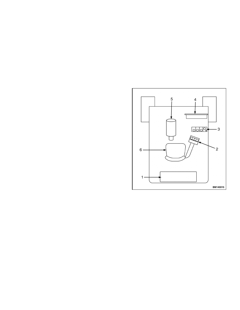
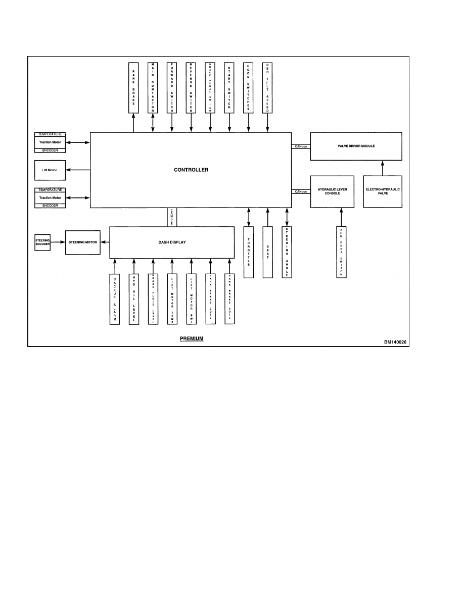
See Figure 1. The lever console, valve driver mod-
ule, and pump motor controller communicate with
each other via the CANbus communication system on
the lift truck. This allows the lever console to send
signals to the valve driver module over a small ca-
ble. Signals from the levers are received by the valve
driver module and are then sent to the electro-hy-
draulic valve solenoid coils to open or close the valve
spools. The lever signal is also received by the slave
controller in the traction control through the CAN-
bus. The slave controller uses these signals to turn
on the pump motor. Pump speed is variable up to the
maximum speed preset in the pump motor controller
for the required hydraulic function. See Figure 2.
1.
TRACTION/PUMP MOTOR CONTROLLER
2.
LEVER CONSOLE
3.
ELECTRO-HYDRAULIC CONTROL VALVE
4.
VALVE DRIVER MODULE
5.
PUMP AND MOTOR ASSEMBLY
6.
SEAT
Figure 1. Component Location
1
Description
2000 SRM 1086
Figure 2. Logic Diagram - Electro-Hydraulic Controls
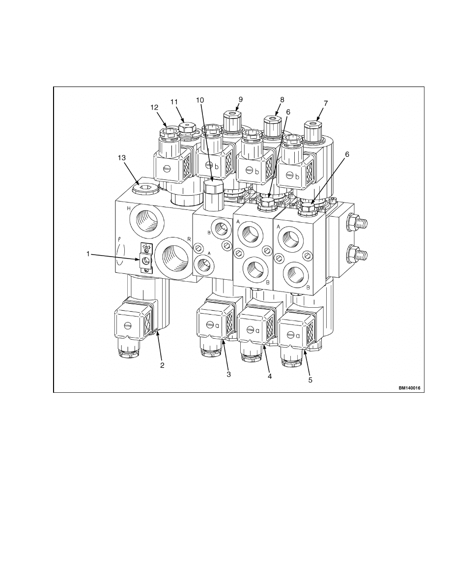
ELECTRO-HYDRAULIC CONTROL VALVE
The electro-hydraulic control valve is modular in de-
sign. Control valve sections are stacked together to
assemble the control valve assembly. Control valve
sections may be combined to provide a two-, three-,
or four-spool valve. See Figure 3 and Figure 4.
The basic valve consists of a lift section and a tilt
section. Additional sections are added to the valve
to provide auxiliary hydraulic functions.
The lift section contains a lift proportional control
cartridge, lower proportional control cartridge, relief
valve, manual lowering valve, and a load check valve.
The tilt section contains a spring-centered spool, two
solenoid coils, a counterbalance valve, and a pressure
compensating valve.
The auxiliary control sections contain a spring-cen-
tered spool, two solenoid coils, a pressure compen-
sating valve, and two crossover relief valves.
The valve is fully proportional. This means the valve
spools move in proportion to the amount of movement
of the correct hydraulic lever. A small movement of
the hydraulic lever will result in a small movement
of the valve spool. The movement of the valve spool
will allow pressurized oil from the hydraulic pump
to flow to a hydraulic function. Further movement of
the hydraulic lever will result in an increased flow of
hydraulic oil through the valve.
2
2000 SRM 1086
Description
The valve spool movement is controlled by the
amount of electrical current sent to the solenoid coil
attached to the spool. Varying the current to the
valve spool determines the movement of the spool.
Moving the spool further from the center position
increases the flow of hydraulic oil through the valve.
1.
MANUAL LOWERING VALVE
2.
LIFT CONTROL (WORK PORT H)
3.
TILT CONTROL (WORK PORT A)
4.
AUXILIARY CONTROL #1 (WORK PORT A)
5.
AUXILIARY CONTROL #2 (WORK PORT A)
6.
AUXILIARY RELIEF VALVE
7.
AUXILIARY CONTROL #2 (WORK PORT B)
8.
AUXILIARY CONTROL #1 (WORK PORT B)
9.
TILT CONTROL (WORK PORT B)
10. COUNTERBALANCE VALVE
11. LOWER CONTROL (WORK PORT R)
12. MAIN RELIEF VALVE
13. LOAD CHECK
Figure 3. Electro-Hydraulic Control Valve
3
Description
2000 SRM 1086
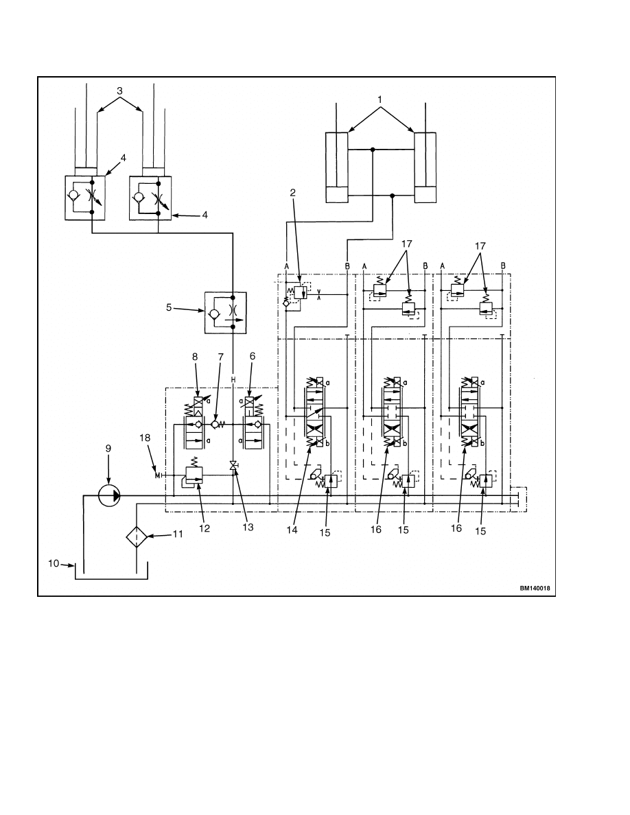
1.
TILT CYLINDERS
2.
TILT COUNTERBALANCE VALVE
3.
LIFT CYLINDERS
4.
LOWERING CONTROL (INTERNAL)
5.
LOWERING CONTROL (EXTERNAL)
6.
LOWER PROPORTIONAL CARTRIDGE
7.
LOAD CHECK VALVE
8.
LIFT PROPORTIONAL CARTRIDGE
9.
HYDRAULIC PUMP
10. HYDRAULIC TANK
11. FILTER
12. MAIN RELIEF VALVE
13. MANUAL LOWERING VALVE
14. TILT SPOOL
15. PRESSURE COMPENSATING VALVE
16. AUXILIARY SPOOL
17. CROSSOVER RELIEF VALVE
18. SUPPLY PRESSURE GAGE PORT
Figure 4. Control Valve Schematic
4
2000 SRM 1086
Electro-Hydraulic Control Valve
VALVE DRIVER MODULE
The valve driver module is a solid-state logic device
that receives signals from the control lever console
over the CANbus and sends signals to the electro-
hydraulic valve.
MANUAL LOWERING VALVE
CAUTION
Turn the manual lowering valve counterclock-
wise to the closed position before placing the
lift truck into service.
The mast may be lowered using the manual lowering
valve located on the Lift/Lower section of the main
control valve. See Figure 3. Turn the lowering valve
screw clockwise into the valve housing to open the
lowering valve to lower the mast.
HYDRAULIC LEVER CONSOLE
The hydraulic lever console is mounted on the
right-hand armrest of the seat. The console contains
the levers needed to control the hydraulic functions
supplied with the lift truck. The levers are paddle
shaped and can be moved in the forward or back-
ward direction.
Lever location and operation are
consistent with the requirements of ANSI B56.1
and are identical in operation to the levers supplied
with the standard manual control valve. Each lever
has a Hall Effect sensor that produces the output
signal to a microprocessor in the lever module. The
microprocessor converts the signals so they can be
sent over the CANbus to the valve driver module
and the slave controller in the traction control.
Each individual control lever produces an electrical
signal that is proportional to the amount of lever
movement - the greater the movement of the lever,
the greater the output signal from the lever. Power
to the lever console is 12 volts supplied from the valve
driver module.
Electro-Hydraulic Control Valve
REMOVE
WARNING
Before making any repairs to the control valve,
tilt the forks until they are parallel with the
floor. Lower the mast until the forks rest on
the floor.
This action will prevent the mast
from lowering suddenly when the hydraulic
lines are disconnected.
WARNING
Put blocks on both sides (front and back) of the
drive tires.
1.
Turn the key to the ON position.
2.
To relieve hydraulic pressure from the lift circuit,
hold the lower lever in the forward position to
completely lower the forks.
3.
To relieve hydraulic pressure in the tilt circuit,
hold the tilt lever in the forward position to com-
pletely tilt the forks forward.
4.
Turn the key switch to the OFF position.
5.
Release the locking mechanism retaining the
hood and raise the hood.
WARNING
The battery is heavy and should be removed
carefully to avoid causing damage or injury.
Use care to avoid injury. Do NOT put hands,
arms, feet, or legs between the battery and a
solid object.
6.
Disconnect the battery and separate the connec-
tor halves. Remove the battery to gain access
to the mounting capscrews for the control valve.
Follow the instructions in the section Periodic
Maintenance 8000 SRM 1079 for battery re-
moval information.
7.
Remove the floor plates to gain access to the con-
trol valve.
5
Electro-Hydraulic Control Valve
2000 SRM 1086
WARNING
Hydraulic oil is hot after system operation and
can cause burns. Do not disconnect any hy-
draulic lines until the oil in the system is cool.
NOTE: Removal of the control valve may result in the
spillage of hydraulic oil as lines are removed. Place
an appropriate container under the lift truck in the
area of the control valve to catch any spillage.
8.
Disconnect all electrical connections from the
valve solenoids.
Remove the screw from the
front of the solenoid coil connectors and pull the
connector away from the coil. Tag all wires to
assist with reassembly of the control valve.
9.
Mark and disconnect the hydraulic hoses at the
fittings on the control valve. Drain any excess
hydraulic oil into a suitable container. Install
plugs in the hydraulic lines to prevent leaking
and to prevent dirt from entering the system.
WARNING
The electro-hydraulic valve assembly is heavy.
Be sure all lifting devices (hoists, chains,
slings, etc.) are suitable and of adequate ca-
pacity to lift the control valve. The hydraulic
control valve can weigh 11.4 to 13.6 kg (25 to
30 lb) without any attachments.
10. Locate and remove the top valve retainer clamp.
Carefully lift the control valve out of the two
bottom valve retainers and remove from the lift
truck.
11. Move the control valve to a workbench for disas-
sembly. Clean the exterior of the control valve
before attempting repairs.
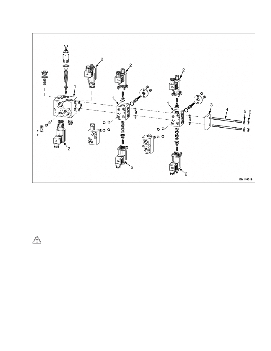
DISASSEMBLE
Disassemble the main control valve as necessary for
repairs. Most repairs to the main control valve are
for the replacement of O-rings and seals to stop leaks.
The passages in the spools and valve body are small
and can need cleaning if the hydraulic oil becomes
dirty. Normally, a section must be replaced if the
spool or valve section is damaged. See Figure 5 for
the following disassembly procedures.
1.
Remove the valve assembly from the valve
mounting plate.
2.
Remove the fittings from the control valve. In-
spect fittings for damage and replace any dam-
aged fittings.
3.
The entire control valve may be disassembled by
removing the nuts, washers, and end plate from
the valve assembly.
4.
The main control valve sections may be sepa-
rated, as required to service individual compo-
nents, by sliding them off the two valve mounting
studs attached to the lift valve section. The sec-
tions are connected by O-rings, which are held in
place by the next valve body section.
5.
Valve section coils may be removed by removing
the retaining ring, washer, and O-ring at the top
of the valve spool. Slide the coil off the valve.
Note the orientation of the coil and the connector
for reassembly.
6.
Remove the valve spools by removing the four
socket head capscrews retaining the spool end
cap to the valve body. Remove the end cap and
slide the spool from the valve body.
CLEAN AND INSPECT
WARNING
Cleaning solvents can be flammable and toxic
and can cause skin irritation.
When using
cleaning solvents, always follow the solvent
manufacturer’s recommended safety proce-
dures.
1.
Clean only the metallic parts of the control valve
with solvent. Do not get solvent in the electrical
connectors or other plastic parts.
2.
Check the spools and bores for wear or damage.
If a spool or the bores have damage, the control
valve section must be replaced. Make sure the
spools move freely in the section bores.
3.
Inspect check valves and relief valves for dam-
age. Replace the parts as necessary.
4.
Check all O-ring mounting seats for nicks or
burrs. Replace any section that has a damaged
O-ring seat.
6
2000 SRM 1086
Electro-Hydraulic Control Valve
1.
MAIN VALVE SECTIONS
2.
VALVE SECTION COILS
3.
END PLATE
4.
VALVE MOUNTING STUDS
5.
WASHER
6.
NUT
Figure 5. Control Valve Assembly
ASSEMBLE
See Figure 5 for the following assembly procedures.
CAUTION
Before installing the parts into the valve body,
make sure all parts are clean. Replace all seals
and O-rings.
Lubricate moving parts with clean hydraulic oil dur-
ing assembly of the control valve.
Lift Valve Section
Install the lift and lower cartridges into the lift
valve section body. Torque the cartridges to 40 N•m
(29.5 lbf ft).
Tilt/Auxiliary Valve Sections
1.
Carefully slide the valve spool into the valve
body.
Install the spool end cap and torque
the four socket head capscrews to 4.7 N•m
(41.60 lbf in).
2.
Install new O-ring seals between the sections.
3.
Slide the section onto the two valve mounting
studs attached to the lift section.
4.
Assemble the tilt section next to the lift section
with the “B” port at the bottom of the valve.
5.
Assemble the auxiliary sections with the “A” port
at the bottom of the valve.
6.
Install the end plate, washers, and nuts. Torque
the nuts to 23 N•m (16.96 lbf ft).
7
Electro-Hydraulic Control Valve
2000 SRM 1086
Valve Spool Coils
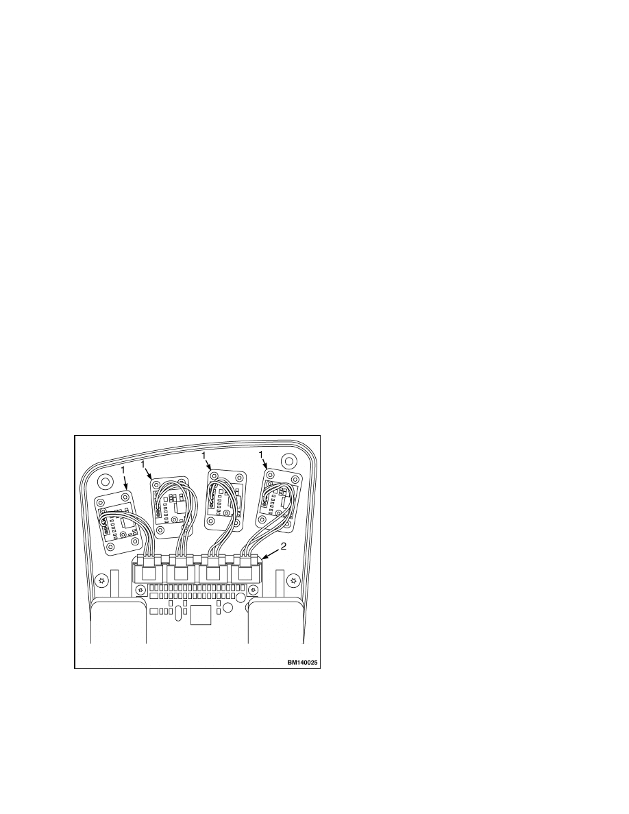
1.
Install coils on spool end caps.
2.
The coil connections should be oriented toward
the front of the valve and to the top or the bottom
of the valve as shown in Figure 6.
3.
Install the O-rings, washers, and retaining rings
to retain the coil to the spool end cap.
Fittings
Install fittings into the valve assembly. See Figure 6.
Figure 6. Fitting Orientation
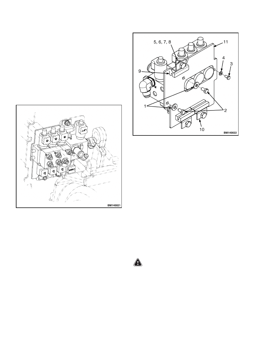
INSTALL
1.
Install the valve assembly onto the valve mount-
ing plate. See Figure 7. Install the capscrews
and washers through the back of the mounting
plate into the valve.
Torque capscrews (2) to
19 N•m (14 lbf ft). Torque capscrew (3) to 8 N•m
(6 lbf ft).
2.
Install the valve and mounting plate into the
truck frame. Set the mounting plate into the
two bottom isolators attached to the frame. In-
stall the top isolator and mounting hardware.
See Figure 7. Torque the mounting hardware to
38 N•m (28 lbf ft).
1.
WASHER
2.
CAPSCREW
3.
CAPSCREW
4.
WASHER
5.
CAPSCREW
6.
WASHER
7.
WASHER
8.
NUT
9.
ISOLATOR
10. BRACKET
11. MOUNTING PLATE
Figure 7. Control Valve Mounting
3.
Install the pressure line from the hydraulic
pump.
4.
Install hoses to auxiliary and tilt sections in the
order they were removed.
5.
Install the return line between the valve and the
hydraulic tank.
6.
Install the pressure line to the mast.
7.
Install all wiring connections to the valve.
8.
Check hydraulic fluid in the hydraulic tank and
replenish if needed.
WARNING
The battery is heavy and should be installed
carefully to avoid causing damage or injury.
Use care to avoid injury. Do NOT put hands,
arms, feet, or legs between the battery and a
solid object.
9.
Install battery.
10. Connect battery to the truck.
8
2000 SRM 1086
Valve Driver Module
11. Turn the key to the ON position.
12. Operate the lift truck through all hydraulic func-
tions and check for correct operation. Ensure all
hydraulic functions operate in the correct direc-
tion according to the hydraulic function label on
the control lever. If the direction is incorrect, re-
verse the hydraulic hoses at the correct valve sec-
tion.
13. Check for leaks.
14. Remove drip pan used during the repair.
15. Remove all blocks from the lift truck wheels.
CHECK AND ADJUST
Tilt Counterbalance Valve
1.
Tilt the mast to the full back position with a load
on the forks.
2.
Disable the hydraulic motor so the motor cannot
run.
NOTE: If after completing Step 3 the mast does not
begin to drift forward, the counterbalance valve is
working properly. If after completing Step 3 the mast
begins to drift forward, the counterbalance valve is
not working properly.
3.
Press the tilt lever forward to open the tilt valve.
The tilt counterbalance valve is non-adjustable with
a setting of 20.7 ±0.5 MPa (3000 ±75 psi).
Main Relief Valve
1.
Install a 25 MPa (3600 psi) pressure gauge to
the supply pressure gauge port on the side of the
electro-hydraulic valve. See Figure 4.
2.
Loosen the lock nut at the base of the adjustment
screw.
3.
Move the adjustment screw in or out of the valve
to adjust the relief pressure.
4.
The pressure should be set at 17.9 MPa
(2600 psi).
5.
Lock the adjustment screw in place with the lock
nut.
Auxiliary Relief Valve
The auxiliary relief valves are non-adjustable with a
setting of 13.8 ±0.5 MPa (2000 ±75 psi).
Valve Driver Module
There are no serviceable parts within the valve
driver module. If there is an internal fault within
the valve driver module, the module must be re-
placed.
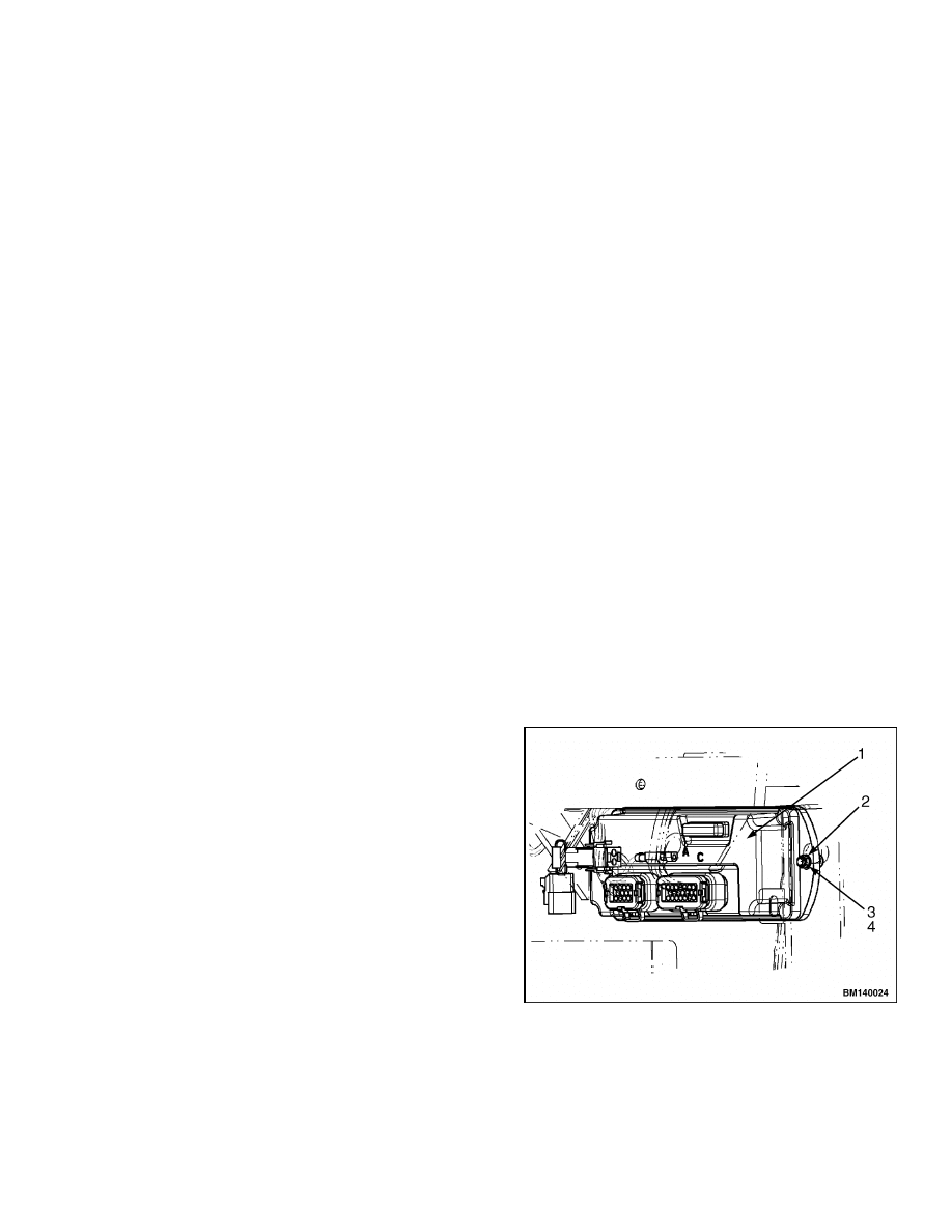
REMOVE
The valve driver module is located on the front cowl
underneath the dash panel on the right hand side of
the lift truck.
1.
Unplug the two connectors from the main har-
ness and tag them for later installation.
2.
Remove the capscrews, lockwashers, and nuts
holding the valve driver module to the front cowl.
See Figure 8.
3.
Remove the valve driver module from the lift
truck.
1.
VALVE DRIVER
MODULE
2.
CAPSCREW
3.
LOCKWASHER
4.
NUT
Figure 8. Valve Driver Module
9
Hydraulic Lever Console
2000 SRM 1086
INSTALL
1.
Locate the mounting holes for the valve driver
module on the front cowl.
2.
Install the valve driver module using the cap-
screws, lockwashers, and nuts as shown in Fig-
ure 8.
Hydraulic Lever Console
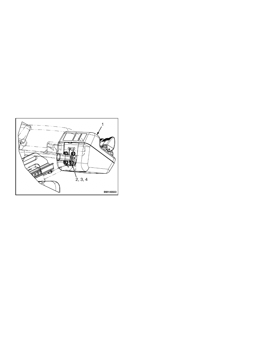
REMOVE
1.
Push down on the latch on the right-hand side of
the arm rest housing the lever module and raise
the arm rest.
2.
Locate and disconnect the electrical connector at
the back of the lever module. See Figure 9. Tag
the connector for later installation.
1.
LEVER MODULE
2.
NUT
3.
WASHER
4.
LOCKWASHER
Figure 9. Lever Module Mounting
3.
Remove the four nuts, washers, and lockwashers
from the back of the lever module. See Figure 9.
Take care when removing that the lever module
does not fall when the capscrews are removed.
4.
Remove the lever module from the lift truck.
DISASSEMBLE
Covers
1.
Remove the four screws from the bottom of the
lever console assembly.
2.
Separate the two halves of the console cover.
3.
Place the assembly upside down on the bench.
Hydraulic Control Lever
NOTE: The individual hydraulic lever assemblies can
be removed from the lever console assembly without
removing the console mounting plate or the main PC
board.
1.
Disconnect the lever wiring connector from the
main PC board. Press the locking tab next to
the wiring coming from the levers to release the
connector from the PC board.
2.
Remove the four screws retaining the lever as-
sembly to the upper cover.
3.
Remove the two screws holding the lever PC
board to the lever assembly.
Main PC Board
1.
Clip the wire tie holding the lever harness to the
lever mounting plate.
2.
Remove the two screws holding the console
mounting plate to the upper cover.
3.
Disconnect the lever wiring connectors from the
main PC board. Press the locking tab next to
the wiring coming from the levers to release the
connector from the PC board.
4.
Remove the console mounting plate.
5.
Remove the four screws retaining the main PC
board to the upper cover.
10
2000 SRM 1086
Hydraulic Lever Console
ASSEMBLE
Main PC Board
1.
Install the main PC board to the upper cover us-
ing the four PC board mounting screws.
2.
Insert the PC board wiring harness through the
opening in the console mounting plate.
3.
Install the mounting plate to the upper cover us-
ing the two mounting screws. Wire-tie the har-
ness using the wire-tie connection on the mount-
ing plate.
4.
Install the lever assembly wiring connectors to
the main PC board. Insert the connector into
the main PC board until the connector lock is
engaged.
Hydraulic Control Lever
1.
Insert the lever PC board into the lever and in-
stall the two mounting screws.
2.
Ensure the sealing ring is properly installed in
the lever assembly. Install the lever assembly to
the upper cover with the four mounting screws.
Ensure the wiring on the lever PC board is on the
left hand side as shown in Figure 10.
Figure 10. Lever Assembly PC Board
Installation
Legend for Figure 10
1.
LEVER PC BOARD
2.
MAIN PC BOARD
NOTE: Installing the lever assembly incorrectly will
result in incorrect operation of the function operated
by the lever.
3.
Install the lever assembly wiring connector to the
main PC board. Insert the connector into the
main PC board until the connector lock is en-
gaged.
Covers
Install the lower cover to the upper cover using the
four mounting screws.
INSTALL
1.
Place the lever console assembly on the end of the
right-hand arm rest. See Figure 9.
2.
Install the washers, lockwashers, and nuts.
3.
Connect the connector from the seat wiring har-
ness.
4.
Connect the battery.
5.
Turn the key to the ON position.
6.
Activate all levers and ensure all hydraulic func-
tions operate correctly.
11

Troubleshooting
2000 SRM 1086
Troubleshooting
When a fault occurs in the electrical circuits of the
electro-hydraulic controls, an error code will be
displayed on the dash display.
See the listing of
error codes below. See the section AC Motor Con-
trollers/Display Panel, Description, Checks,
Adjustments, and Troubleshooting 2200 SRM
1087 for operation of the dash display and a com-
plete explanation of the electro-hydraulic error codes
used to troubleshoot the electro-hydraulic controls
system.
Table 1. Error Codes
Code 42
Lift control temperature too high.
Code 270
Error in lift hydraulic lever.
Code 91
Lift motor temperature too high.
Code 271
Error in tilt hydraulic lever.
Code 95
Lift motor brushes worn.
Code 272
Error in sideshift hydraulic lever.
Code 128
Lift motor armature current too
high.
Code 273
Error in 4th function hydraulic
lever.
Code 201
Arm rest switch not closed.
Code 276
Lift driver is shorted in valve driver
module.
Code 202
Hydraulic oil low.
Code 277
4th function driver is shorted in
valve driver module.
Code 208
Incorrect lift motor start.
Code 279
Tilt driver is shorted in valve driver
module.
Code 242
Master controller CAN error with
hydraulic lever console.
Code 280
Sideshift driver is shorted in valve
driver module.
Code 243
Master controller CAN error with
valve driver module.
Code 282
Load hold driver is shorted in valve
driver module.
Code 247
Valve driver module CAN error with
dash display.
Code 283
One of the valve coils is shorted.
Code 260
Incorrect voltage at the motor.
TROUBLESHOOTING CHART
PROBLEM
POSSIBLE CAUSE
PROCEDURE OR ACTION
Slow or no movement of
cylinders.
Air is in hydraulic system.
Remove air from hydraulic system.
Hydraulic pump is worn or damaged.
Repair or replace hydraulic pump.
See the section Hydraulic System
1900 SRM 1077 for repair proce-
dures.
Restriction in hydraulic lines.
Repair hydraulic lines.
12

2000 SRM 1086
Troubleshooting
PROBLEM
POSSIBLE CAUSE
PROCEDURE OR ACTION
Slow or no movement of
cylinders. (Cont.)
Cylinder seals are damaged.
Repair cylinder.
See the section
Tilt Cylinders 2100 SRM 103 for
tilt cylinder repair. See the section
Mast, Repairs 4000 SRM 522 for
lift cylinder repair.
Load is greater than capacity.
Reduce the load.
Pressure relief valve(s) is not ad-
justed correctly or is damaged.
Repair or adjust relief valve(s). See
Main Relief Valve.
Large leaks between spool and bore.
Replace valve section.
Incorrect
operation
of
solenoid
valves.
Check display for fault code. See the
section AC Motor Controllers/Dis-
play Panel, Description, Checks,
Adjustments, and Troubleshoot-
ing 2200 SRM 1087 for fault code in-
formation.
Manual lowering valve is open.
Close manual lowering valve on Lift/
Lower section of main control valve.
Pump motor fails to turn on.
Failure of function lever.
Check display for fault code. See the
section AC Motor Controllers/Dis-
play Panel, Description, Checks,
Adjustments, and Troubleshoot-
ing 2200 SRM 1087 for fault code in-
formation.
Failure of pump motor controller.
Check display for fault code. See the
section AC Motor Controllers/Dis-
play Panel, Description, Checks,
Adjustments, and Troubleshoot-
ing 2200 SRM 1087 for fault code in-
formation.
Failure of valve driver module.
Check display for fault code. See the
section AC Motor Controllers/Dis-
play Panel, Description, Checks,
Adjustments, and Troubleshoot-
ing 2200 SRM 1087 for fault code in-
formation.
Failure of CANbus.
Check display for fault code. See the
section AC Motor Controllers/Dis-
play Panel, Description, Checks,
Adjustments, and Troubleshoot-
ing 2200 SRM 1087 for fault code in-
formation.
13

Troubleshooting
2000 SRM 1086
PROBLEM
POSSIBLE CAUSE
PROCEDURE OR ACTION
Pump motor fails to turn on.
(Cont.)
Failure of pump motor.
Check display for fault code. See the
section AC Motor Controllers/Dis-
play Panel, Description, Checks,
Adjustments, and Troubleshoot-
ing 2200 SRM 1087 for fault code in-
formation.
Oil leaks at end of spool.
Seal for spool is damaged.
Replace the seal.
Spool is damaged.
Replace the spool.
Valve body is damaged.
Replace the valve section.
Tilt cylinders extend when
tilt spool is in the neutral
position.
Cylinder has leaks.
Repair or replace cylinder.
Leakage between the tilt spool and
bore.
Replace the valve section.
Hydraulic lines are leaking.
Repair or tighten lines.
Lift
cylinder(s)
retracts
when lift spool is in the
neutral position.
Load hold check valve is damaged.
Inspect check valve for contamina-
tion or damage.
Clean or replace
check valve.
Cylinder seals have leaks.
Repair lift cylinder.
Hydraulic lines have leaks.
Repair or tighten lines.
Leakage between lift spool and bore.
Replace the valve section.
No function operation.
Failure of function lever.
Check display for fault code. See the
section AC Motor Controllers/Dis-
play Panel, Description, Checks,
Adjustments, and Troubleshoot-
ing 2200 SRM 1087 for fault code in-
formation.
Failure of function spool solenoid
coil.
Check display for fault code. See the
section AC Motor Controllers/Dis-
play Panel, Description, Checks,
Adjustments, and Troubleshoot-
ing 2200 SRM 1087 for fault code in-
formation.
14

2000 SRM 1086
Troubleshooting
PROBLEM
POSSIBLE CAUSE
PROCEDURE OR ACTION
No
function
operation.
(Cont.)
Failure of valve driver module.
Check display for fault code. See the
section AC Motor Controllers/Dis-
play Panel, Description, Checks,
Adjustments, and Troubleshoot-
ing 2200 SRM 1087 for fault code in-
formation.
Failure of CANbus.
Check display for fault code. See the
section AC Motor Controllers/Dis-
play Panel, Description, Checks,
Adjustments, and Troubleshoot-
ing 2200 SRM 1087 for fault code in-
formation.
Failure of pump motor.
Check display for fault code. See the
section AC Motor Controllers/Dis-
play Panel, Description, Checks,
Adjustments, and Troubleshoot-
ing 2200 SRM 1087 for fault code
information.
See the section Hy-
draulic System 1900 SRM 1077 for
repair procedures.
Failure of pump motor controller.
Check display for fault code. See the
section AC Motor Controllers/Dis-
play Panel, Description, Checks,
Adjustments, and Troubleshoot-
ing 2200 SRM 1087 for fault code in-
formation.
No or low flow from pump.
Worn pump.
Repair or replace pump. See the sec-
tion Hydraulic System 1900 SRM
1077 for repair procedures.
Incorrect relief valve setting.
Set relief valve to correct pressure
setting. See Main Relief Valve.
15

NOTES
____________________________________________________________
____________________________________________________________
____________________________________________________________
____________________________________________________________
____________________________________________________________
____________________________________________________________
____________________________________________________________
____________________________________________________________
____________________________________________________________
____________________________________________________________
____________________________________________________________
____________________________________________________________
____________________________________________________________
____________________________________________________________
____________________________________________________________
____________________________________________________________
____________________________________________________________
____________________________________________________________
____________________________________________________________
____________________________________________________________
16


TECHNICAL PUBLICATIONS
2000 SRM 1086
6/04 Printed in United Kingdom
Document Outline
- toc
- tables
Wyszukiwarka
Podobne podstrony:
1554631 2000SRM1085 (03 2004) UK EN
1554635 8000SRM1079 (06 2004) UK EN
1554630 1900SRM1077 (06 2004) UK EN
1554631 2000SRM1085 (03 2004) UK EN
1554635 8000SRM1079 (06 2004) UK EN
1565454 8000SRM1113 (06 2004) UK EN
1554636 8000SRM1080 (11 2004) UK EN
897494 1900SRM0513 (06 2004) UK EN
1554626 0100SRM1073 (06 2004) UK EN
1565181 2000SRM1108 (08 2004) UK EN
897559 0100SRM0545 (06 2004) UK EN
897880 1400SRM0618 (06 2004) UK EN
897881 1600SRM0619 (06 2004) UK EN
więcej podobnych podstron