HYDRAULIC SYSTEM
S2.00-3.20XM (S40-65XM) [D187];
H2.00-3.20XM (H40-65XM) [D177];
H2.00-3.20XM (H45-65XM) [H177]
PART NO. 897494
1900 SRM 513
SAFETY PRECAUTIONS
MAINTENANCE AND REPAIR
• When lifting parts or assemblies, make sure all slings, chains, or cables are correctly
fastened, and that the load being lifted is balanced. Make sure the crane, cables, and
chains have the capacity to support the weight of the load.
• Do not lift heavy parts by hand, use a lifting mechanism.
• Wear safety glasses.
• DISCONNECT THE BATTERY CONNECTOR before doing any maintenance or repair
on electric lift trucks. Disconnect the battery ground cable on internal combustion lift
trucks.
• Always use correct blocks to prevent the unit from rolling or falling. See HOW TO PUT
THE LIFT TRUCK ON BLOCKS in the Operating Manual or the Periodic Mainte-
nance section.
• Keep the unit clean and the working area clean and orderly.
• Use the correct tools for the job.
• Keep the tools clean and in good condition.
• Always use HYSTER APPROVED parts when making repairs. Replacement parts
must meet or exceed the specifications of the original equipment manufacturer.
• Make sure all nuts, bolts, snap rings, and other fastening devices are removed before
using force to remove parts.
• Always fasten a DO NOT OPERATE tag to the controls of the unit when making repairs,
or if the unit needs repairs.
• Be sure to follow the WARNING and CAUTION notes in the instructions.
• Gasoline, Liquid Petroleum Gas (LPG), Compressed Natural Gas (CNG), and Diesel fuel
are flammable. Be sure to follow the necessary safety precautions when handling these
fuels and when working on these fuel systems.
• Batteries generate flammable gas when they are being charged. Keep fire and sparks
away from the area. Make sure the area is well ventilated.
NOTE: The following symbols and words indicate safety information in this
manual:
WARNING
Indicates a condition that can cause immediate death or injury!
CAUTION
Indicates a condition that can cause property damage!
Hydraulic System
Table of Contents
TABLE OF CONTENTS
General ...............................................................................................................................................................
Description .........................................................................................................................................................
Hydraulic System ..........................................................................................................................................
Gear Pump Assembly ....................................................................................................................................
Flow Control Valve ........................................................................................................................................
Relief Valve ....................................................................................................................................................
Operation............................................................................................................................................................
Hydraulic System ..........................................................................................................................................
Gear Pump .....................................................................................................................................................
Flow Control Valve ........................................................................................................................................
Relief Valve ....................................................................................................................................................
Gear Pump Assembly Repair ............................................................................................................................
Remove and Disassemble ..............................................................................................................................
Assemble and Install .....................................................................................................................................
Steering Relief Pressure Check and Adjustment.............................................................................................
Gear Pump Flow Check .....................................................................................................................................
Troubleshooting..................................................................................................................................................
This section is for the following models:
S2.00-3.20XM (S40-65XM) [D187];
H2.00-3.20XM (H40-65XM) [D177];
H2.00-3.20XM (H45-65XM) [H177]
©2004 HYSTER COMPANY
i

"THE
QUALITY
KEEPERS"
HYSTER
APPROVED
PARTS

1900 SRM 513
Description
General
This section has a description of the hydraulic sys-
tem and the gear pump assembly. Procedures for the
repair of the gear pump assembly are also in this sec-
tion. Repair information for the parts of the steering
system are in the sections Steering Axle 1600 SRM
316 and Steering Housing and Control Unit 1600
SRM 512. Information on the control valve is in the
section Main Control Valve 2000 SRM 516. Infor-
mation for pump drive assembly is in Single-Speed
Powershift Transmission, Troubleshooting and
Repair 1300 SRM 501. The Steering Relief Pressure
Check and Adjustment, Gear Pump Flow Check, and
Troubleshooting for the gear pump assembly are at
the end of this section.
Description
HYDRAULIC SYSTEM
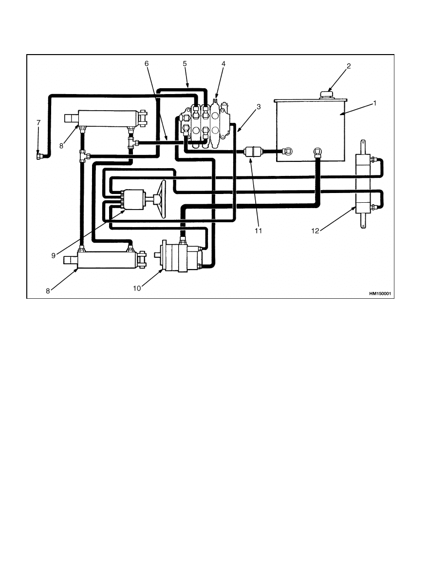
The hydraulic system has the following parts: hy-
draulic tank, gear pump assembly, steering control
unit, main control valve, lift cylinders, tilt cylinders,
steering cylinder, oil filter, and breather. See Fig-
ure 1 and Figure 2. The steering system and the lift
and tilt system are separate circuits of the hydraulic
system. Both circuits use a common hydraulic tank
and gear pump. A breather at the top of the tank lets
air into the hydraulic tank.
GEAR PUMP ASSEMBLY
The gear pump assembly includes the gear pump, a
flow control valve, and a relief valve. See Figure 3,
and Figure 4. The gear pump can have either one or
two sets of gears. The pump with two sets of gears
reduces hydraulic noise. The flow control valve and a
relief valve are in the end housing of the pump. The
inlet is in the side of the pump body. The pump out-
let connects directly to the end housing and the flow
control valve. The flow control valve has the out-
let for the primary flow and the outlet for the sec-
ondary flow. The primary flow is for the steering cir-
cuit. Flow from the relief valve goes to the pump inlet
through an internal passage. Seals prevent leaks be-
tween sections to outside of the pump.
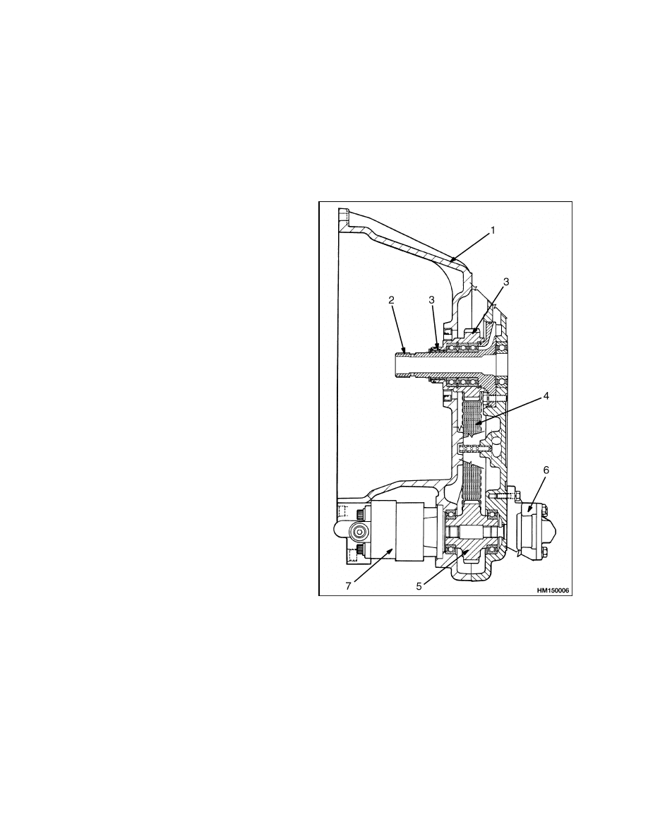
The gear pump is driven by a chain drive arrange-
ment in the transmission. The drive sprocket for the
pump drive is connected by splines to the hub of the
torque converter. The drive sprocket, in turn, drives
the chain, the pump sprocket, and the gear pump.
See Figure 7.
FLOW CONTROL VALVE
The flow control valve makes sure the steering sys-
tem has a constant supply of oil. The flow control
valve has a spring, a plunger with an orifice, and
two plugs with O-rings. See Figure 5. The spring
keeps the plunger in the correct position. Oil pres-
sure can move the plunger and compress the spring.
The plugs keep the plunger and spring in the bore
and also keep the oil in the correct chamber. O-rings
are used on the plugs and the plunger.
RELIEF VALVE
The relief valve for the steering system is in a bore
in the end housing of the gear pump. See Figure 5.
The relief valve prevents the oil pressure in the steer-
ing system from increasing above specifications. The
relief valve has the following parts: a relief valve
housing, a poppet, a spring, an adjuster, a lock nut,
and O-rings. The position of the adjuster and the
amount of compression of the spring determine the
relief pressure. When the adjustment is correct, the
lock nut will hold the adjuster in the correct location
and the O-ring will seal the adjuster against the re-
lief valve housing.
1
Description
1900 SRM 513
1.
HYDRAULIC TANK
2.
BREATHER
3.
RETURN LINE
4.
MAIN CONTROL VALVE
5.
TILT BACKWARD LINE
6.
TILT FORWARD LINE
7.
TO LIFT CYLINDERS
8.
TILT CYLINDER
9.
STEERING CONTROL UNIT
10. HYDRAULIC PUMP
11. FILTER
12. STEERING CYLINDER
Figure 1. Hydraulic System
2
1900 SRM 513
Description
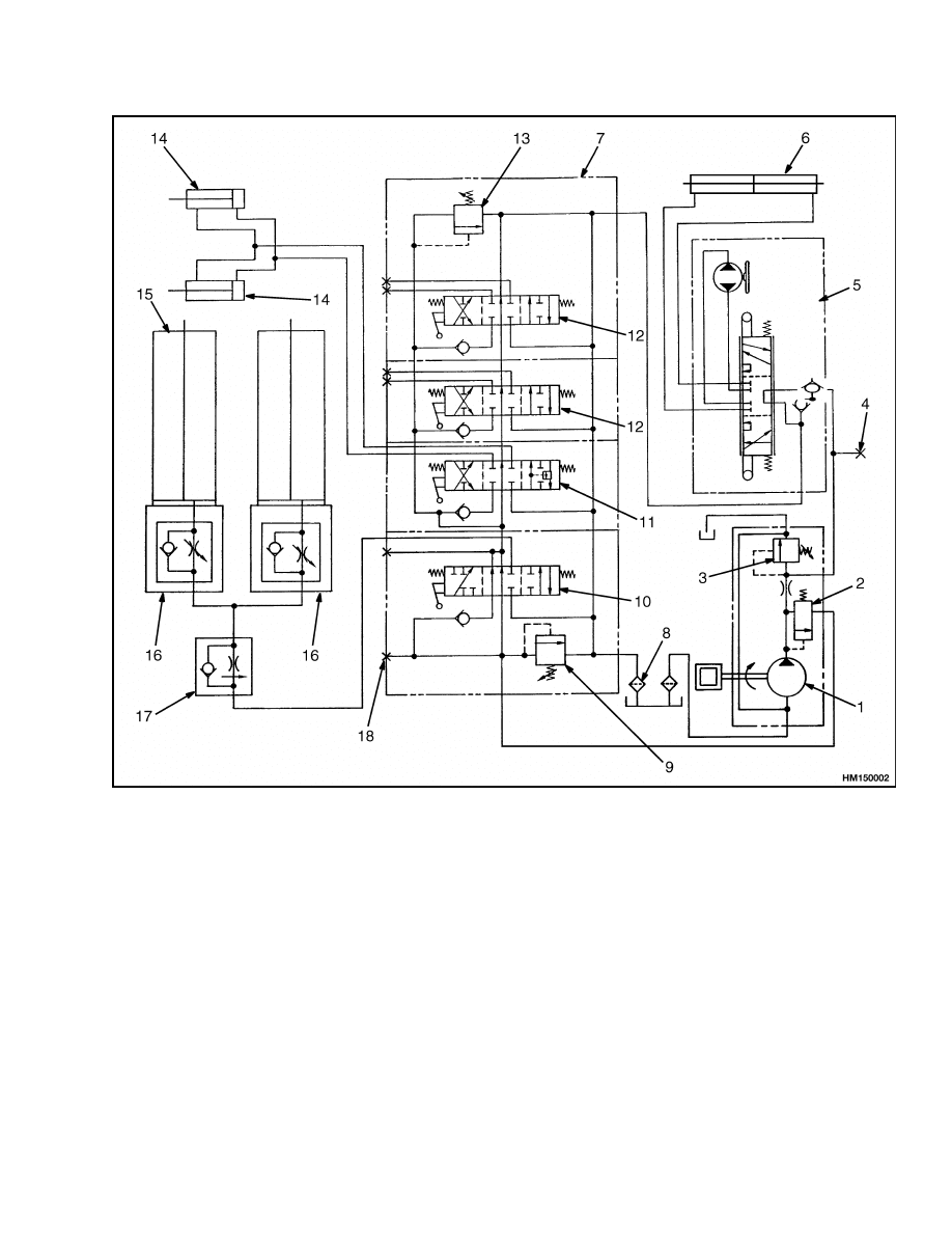
1.
HYDRAULIC PUMP
2.
FLOW CONTROL VALVE
3.
RELIEF VALVE (STEERING SYSTEM)
4.
CHECK PORT (STEERING SYSTEM)
5.
STEERING CONTROL UNIT
6.
STEERING CYLINDER
7.
MAIN CONTROL VALVE
8.
FILTER
9.
RELIEF VALVE (LIFT CIRCUIT)
10. LIFT/LOWER SPOOL
11. TILT SPOOL
12. AUXILIARY FUNCTION SPOOL
13. RELIEF VALVE (TILT AND AUXILIARY CIRCUITS)
14. TILT CYLINDER
15. LIFT CYLINDER
16. LOWERING CONTROL VALVE (INTERNAL)
17. LOWERING CONTROL VALVE (EXTERNAL)
18. CHECK PORT (LIFT AND TILT CIRCUITS)
Figure 2. Hydraulic System Schematic
3
Description
1900 SRM 513
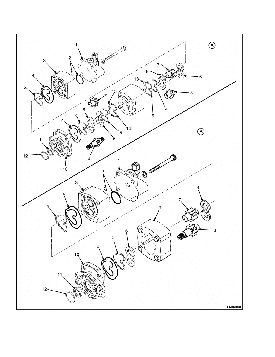
Figure 3. Gear Pump Assembly (Older Models)
4

1900 SRM 513
Description
Legend for Figure 3
A. DUAL GEAR SET HYDRAULIC PUMP
B. SINGLE GEAR SET HYDRAULIC PUMP
1.
VALVE HOUSING
2.
O-RING
3.
END HOUSING
4.
HOUSING SEAL
5.
BACKUP SEAL
6.
PRESSURE PLATE
7.
DRIVEN GEAR
8.
DRIVE GEAR
9.
GEAR HOUSING
10. FLANGE END HOUSING
11. SEAL
12. SNAP RING
13. ISOLATOR
14. PRESSURE PLATE SEAL
5
Description
1900 SRM 513
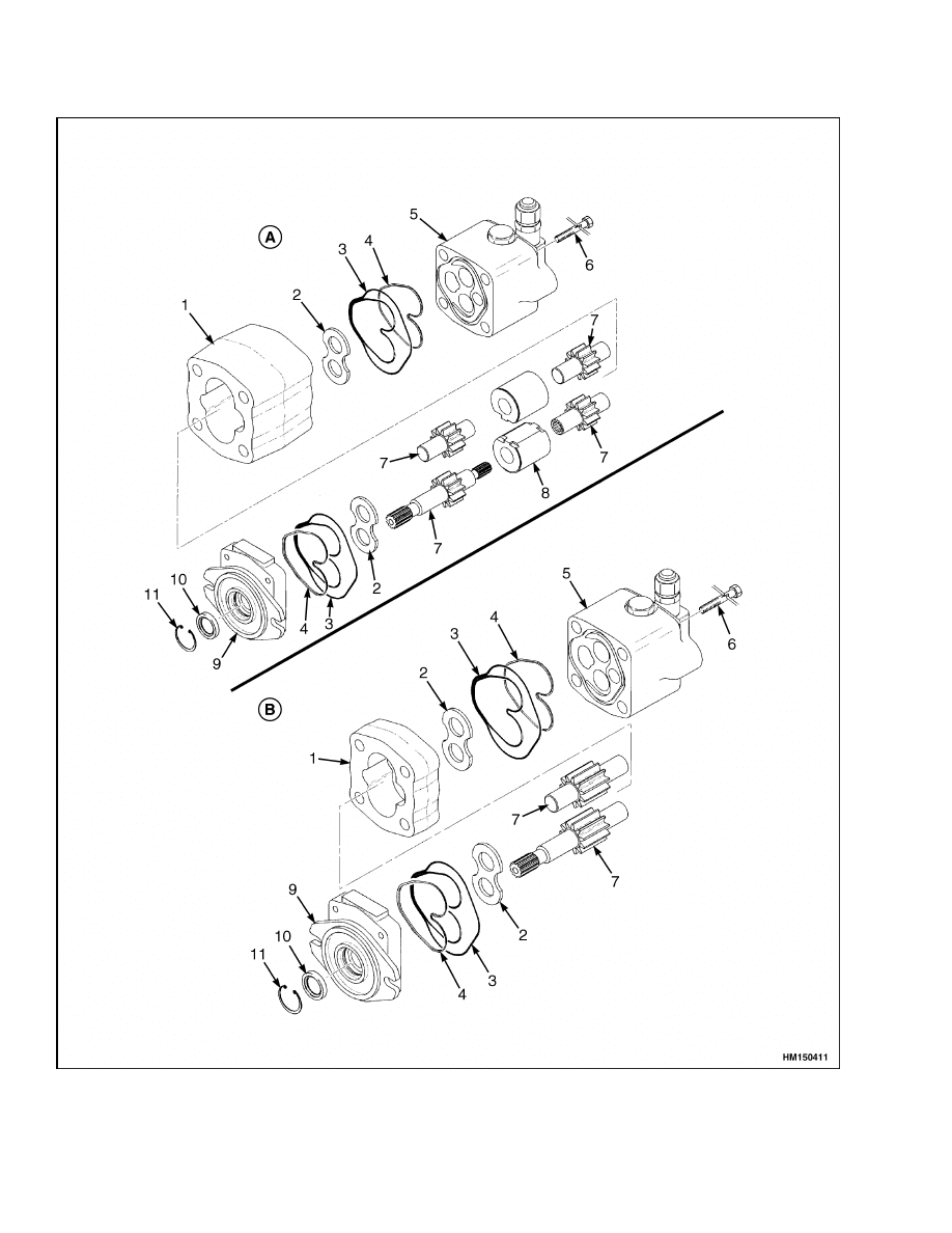
Figure 4. Gear Pump Assembly (Newer Models)
6
1900 SRM 513
Description
Legend for Figure 4
A. DUAL GEAR SET HYDRAULIC PUMP
B. SINGLE GEAR SET HYDRAULIC PUMP
1.
HYDRAULIC PUMP BODY
2.
PLATE
3.
PLATE SEAL
4.
BACKUP RING
5.
BODY ASSEMBLY
6.
SCREW
7.
GEAR SET
8.
BUSH
9.
FLANGE
10. OIL SEAL
11. SNAP RING
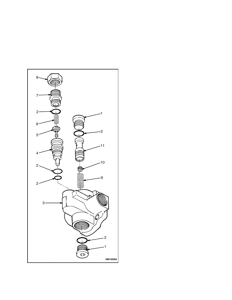
Figure 5. Flow Control Valve and Relief Valve
Parts
Legend for Figure 5
1.
PLUG
2.
O-RING
3.
HOUSING, VALVE
END
4.
HOUSING, RELIEF
VALVE
5.
POPPET, RELIEF
VALVE
6.
RELIEF SPRING
7.
ADJUSTER
8.
LOCK NUT
9.
REGULATOR
SPRING
10. ORIFICE
11. REGULATOR
PLUNGER
7

Operation
1900 SRM 513
Operation
HYDRAULIC SYSTEM
The gear pump sends oil flow to the steering system
and the lift and tilt system. The gear pump receives
oil from the hydraulic tank through a screen at the
outlet of the tank. See Figure 1 and Figure 2. The
oil from the pump flows directly to the flow control
valve. The flow control valve supplies a constant sup-
ply of oil to the steering system. This quantity of oil
flow is controlled by the steering control unit to op-
erate the steering cylinder. The relief valve on the
gear pump assembly limits the pressure in the steer-
ing system.
The secondary flow from the pump goes to the main
control valve. This valve controls the flow of oil to the
lift, tilt, and any auxiliary functions. A relief valve
in the main control valve limits the pressure in the
hydraulic system. Test ports permit checking the re-
lief pressures of each system. The location of the test
ports is shown in Figure 1 and Figure 2. The oil re-
turning from the main control valve flows through a
filter in the return line to the hydraulic tank.
GEAR PUMP
The two gears in the pump have their teeth engaged
in the center of the pump body. See Figure 3, and Fig-
ure 4. The gears have close tolerances between them-
selves and the pump body. When the input shaft is
turned, the drive gear turns the driven gear. The tol-
erances and seals make tight chambers between the
gear teeth. When the teeth of each gear move apart
at the inlet port, they make a vacuum. Oil from the
tank enters the inlet port and is moved by the gear
chambers around the circumference. Passages oppo-
site the inlet connect the gear chambers for outlet oil
flow to the flow control valve. Oil at the inlet flows
through bores and passages in the bushings to both
sides of each bushing. Oil lubricates the bushings
and the gear surface of each bushing. Other bores
and passages in the bushings let the outlet oil go to
the sides of the bushings away from the gears. The
passages also let this outlet oil flow to the side of the
inlet circumference of each bushing. The pressure on
each bushing is kept equal by the passages and the
oil.
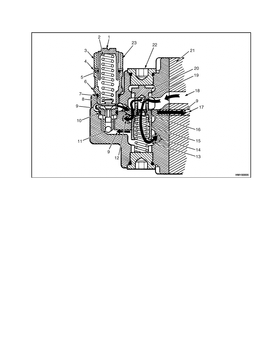
FLOW CONTROL VALVE
The oil at the outlet of the gear pump enters the valve
chamber near the center of the plunger. See Figure 6.
The oil flows through the orifice in the plunger to
the steering system port. This oil also flows to the
relief valve. If the oil flow at the pump outlet is more
than the primary flow for the steering system, the
plunger will move. This plunger movement connects
part of the oil flow to the lift and tilt system port. The
plunger will also move back and decrease or stop the
flow of oil to the lift and tilt system if the pump flow
decreases. The plunger keeps moving to make sure
the steering system always has a constant supply of
oil.
RELIEF VALVE
The pressure in the steering system is sensed at the
relief valve. See Figure 6. If the pressure increases to
the relief valve setting, the poppet in the relief valve
will move against the spring (2). When the poppet
moves off the seat, oil flows through an internal pas-
sage that directs the oil flow to the pump inlet to de-
crease the pressure. The decrease in pressure lets
the spring return the poppet back to the seat.
8
1900 SRM 513
Operation
1.
ADJUSTER
2.
RELIEF SPRING
3.
LOCK NUT
4.
BACKUP RING
5.
O-RING
6.
HOUSING, RELIEF VALVE
7.
O-RING
8.
POPPET
9.
FLOW, RELIEF PRESSURE
10. O-RING
11. CHECK BALL
12. PORT TO LIFT SYSTEM
13. PRIMARY FLOW
14. PORT TO STEERING SYSTEM
15. REGULATOR SPRING
16. ORIFICE
17. INTERNAL PASSAGE FOR RELIEF PRESSURE
TO PUMP INLET
18. PORT, PUMP OUTLET/VALVE INLET
19. SECONDARY FLOW
20. REGULATOR PLUNGER
21. PUMP HOUSING
22. FLOW CONTROL VALVE, REGULATOR
SECTION
23. RELIEF VALVE
Figure 6. Flow Control Valve and Relief Valve Operation
9
Gear Pump Assembly Repair
1900 SRM 513
Gear Pump Assembly Repair
REMOVE AND DISASSEMBLE
NOTE: Worn or damaged seals are the most common
cause of pump damage. The pump bushings, gears,
and shafts also wear. They must be checked during
disassembly. Do not make any repairs to the parts.
To prevent more failures, always replace parts that
are worn or damaged. If several main parts need
replacing, replace the complete group.
1.
If necessary, put a drain pan under the hydraulic
tank. Disconnect the return line at the bottom
of the tank. Drain the oil from the tank. The
drain pan must have capacity of approximately
30 liter (8 gal). See Figure 3, Figure 4, Figure 5,
and Figure 7.
2.
Put a drain pan under the pump assembly. Put
tags on the hydraulic lines for correct connections
during installation. Remove all hydraulic lines
connected to the pump assembly. Put caps on all
the fittings and ports.
3.
Hold the pump assembly to keep it from falling.
Remove the two capscrews and the washers that
fasten the pump to the transmission housing.
Remove the pump assembly.
4.
Put the pump body in a vise. Do not damage the
inlet port. Put an alignment mark on the valve
end housing and the pump body.
5.
Remove the capscrews that hold the pump to-
gether. Remove the flange end housing. Remove
the valve housing. Do not let the seals and gears
fall.
6.
Make a note of the position of the seals. Carefully
remove the oil seals, pressure plates, bushings
(on newer models), and gears from the housings.
Remove the snap ring and shaft seal from the
flange end housing.
7.
Check the parts for wear and damage.
NOTE: If the lock nut is not removed from the ad-
juster, the relief valve setting will not change.
8.
Remove the plugs and O-rings at each end of the
flow control valve. Remove the regulator plunger
and spring. See Figure 5.
9.
Remove the lock nut from the adjuster. Remove
the adjuster and parts of the relief valve. Remove
the relief valve housing. See Figure 5.
1.
HOUSING
2.
STATOR
3.
DRIVE SPROCKET
4.
CHAIN
5.
PUMP SPROCKET
6.
TRANSMISSION
PUMP
7.
HYDRAULIC
SYSTEM PUMP
Figure 7. Pump Drive Arrangement
10

1900 SRM 513
Steering Relief Pressure Check and Adjustment
ASSEMBLE AND INSTALL
1.
Put oil on all parts of the pump and valves. Use
the hydraulic oil shown in the Periodic Main-
tenance section. Make sure to keep the parts
clean. See Figure 3, Figure 4, Figure 5, and Fig-
ure 7.
2.
Install the bottom plug and O-ring for the regu-
lator plunger. See Figure 5. Install the orifice in
the regulator plunger. Install the spring and reg-
ulator plunger in the housing. Install the O-ring
and plug at the top of the housing.
3.
Install the O-rings on the relief valve housing.
See Figure 5. Install the relief valve housing in
the valve end housing. Install the relief valve
poppet and spring. Install the O-ring, adjuster,
and lock nut. Do not tighten the adjuster or lock
nut until the setting is adjusted as described in
Steering Relief Pressure Check and Adjustment.
4.
Use new seals and install the pressure plates,
bushings (on newer models), and gears. Make
sure to install the pressure plates as removed
during disassembly. See the notes made during
disassembly. Make sure all seals are complete
and in the correct positions.
5.
Make sure the dowels are installed in the end
that has the drive shaft and on the side that has
the inlet. Install a new oil seal in the flange end
housing. Put tape on the drive shaft splines and
carefully install the flange end housing. Do not
move the pressure plates. Make sure the seals
do not move out of the correct position.
6.
Carefully install the valve end housing on the
pump body using the four capscrews and lock-
washers. Make sure the pressure plates do not
move and that the seals stay in the correct posi-
tion. Make sure the marks made during disas-
sembly are aligned. Tighten the capscrews to 46
to 49 N•m (34 to 36 lbf ft).
7.
Put a liquid gasket material on the pump flange.
Hold the pump in the correct position on the en-
gine. Install the capscrews and washers that fas-
ten the pump to the transmission housing.
8.
Connect the hydraulic lines as shown by the tags.
Do not tighten the inlet fitting. Fill the tank
using the hydraulic oil shown in the Periodic
Maintenance section. Let some of the oil run
out around the pump inlet fitting. Tighten the
fittings. This procedure will make sure the pump
has oil for first operation.
9.
Adjust the steering relief setting as described in
Steering Relief Pressure Check and Adjustment.
Steering Relief Pressure Check and Adjustment
NOTE: Adjust the relief pressure for the lift and tilt
system as described in the section for the Main Con-
trol Valve Main Control Valve 2000 SRM 516.
1.
Connect a tachometer to the engine. See Figure 1
and Figure 6.
2.
Connect a gate valve and pressure gauge to the
test port located at the tee fitting. The tee fitting
is on the inlet line near the steering control unit.
3.
Operate the engine at 700 rpm. Operate the hy-
draulic system until the oil temperature is 55 to
65 C (130 to 150 F). Turn the steering wheel to
the stop and hold it in that position.
4.
Check the gauge. The correct pressure is 10.6 to
11.7 MPa (1540 to 1700 psi).
5.
If the pressure is less than the specifications,
loosen the lock nut and turn the adjuster for the
relief valve clockwise. See Figure 6. If the pres-
sure is higher than the specification, turn the ad-
juster counterclockwise. After the setting is cor-
rect, hold the adjuster and tighten the lock nut.
6.
Remove the pressure gauge, gate valve, and
tachometer. Install the test port cap.
11

Troubleshooting
1900 SRM 513
Gear Pump Flow Check
NOTE: Make sure the hydraulic oil is at operating
temperature of 35 to 65 C (100 to 150 F).
1.
Install a flow meter in the outlet line of the gear
pump. Follow the manufacturer’s recommended
procedure for operation.
2.
Check the output of the gear pump. The cor-
rect rate for the priority flow is 10.0 liter/min
(2.64 gal/min).
Troubleshooting
PROBLEM
POSSIBLE CAUSE
PROCEDURE OR ACTION
The pump makes too much
noise.
The oil level is low or there is no oil
in the tank.
Check oil level and fill as required.
Check for leaks.
The suction screen has a restriction.
Clean or install new screen.
The inlet fitting is loose.
Tighten fitting.
Install new hoses.
remove air from system.
The bearings or gears have damage.
Repair or install new pump.
The capscrews that hold the pump
together are loose.
Tighten
capscrews
to
specified
torque.
The pump is loose at the transmis-
sion.
Tighten
capscrews
to
specified
torque.
The output of the pump is
less than specifications.
The shafts or gears have damage.
Repair or install new pump.
The seals or gaskets have leaks.
Replace seals.
The fittings at the pump have leaks.
Tighten fitting.
Install new hoses.
remove air from system.
The capscrews that hold the pump
together are loose.
Tighten
capscrews
to
specified
torque.
The flow control valve is damaged.
Replace the flow control valve.
The relief valve is not adjusted cor-
rectly.
Adjust relief valve.
12

1900 SRM 513
Troubleshooting
PROBLEM
POSSIBLE CAUSE
PROCEDURE OR ACTION
The pump has leaks.
The fittings on the pump are loose or
damaged.
Tighten fitting.
Install new hoses.
remove air from system.
The capscrews that hold the pump
together are loose.
Tighten
capscrews
to
specified
torque.
The seals in the pump are damaged.
Replace seals.
The pressure for the steer-
ing system is below specifi-
cations.
The relief valve is not adjusted cor-
rectly.
Adjust relief valve.
The relief valve is damaged.
Replace relief valve.
The pump is worn.
Repair or replace pump.
The flow for the steering sys-
tem is below specifications.
The flow control valve is damaged.
Repair or replace flow control valve.
The relief valve is not adjusted cor-
rectly.
Adjust relief valve.
13

NOTES
____________________________________________________________
____________________________________________________________
____________________________________________________________
____________________________________________________________
____________________________________________________________
____________________________________________________________
____________________________________________________________
____________________________________________________________
____________________________________________________________
____________________________________________________________
____________________________________________________________
____________________________________________________________
____________________________________________________________
____________________________________________________________
____________________________________________________________
____________________________________________________________
____________________________________________________________
____________________________________________________________
____________________________________________________________
____________________________________________________________
14


TECHNICAL PUBLICATIONS
1900 SRM 513
6/04 (12/95)(4/93) Printed in United Kingdom
Document Outline
- toc
Wyszukiwarka
Podobne podstrony:
1554630 1900SRM1077 (06 2004) UK EN
1564283 1900SRM1107 (01 2004) UK EN
1554635 8000SRM1079 (06 2004) UK EN
1565454 8000SRM1113 (06 2004) UK EN
1470232 1900SRM0783 (01 2004) UK EN
1554632 2000SRM1086 (06 2004) UK EN
1466217 1900SRM0743 (06 2005) UK EN
1554626 0100SRM1073 (06 2004) UK EN
897559 0100SRM0545 (06 2004) UK EN
897880 1400SRM0618 (06 2004) UK EN
897881 1600SRM0619 (06 2004) UK EN
1564283 1900SRM1107 (01 2004) UK EN
1554635 8000SRM1079 (06 2004) UK EN
więcej podobnych podstron