INSTRUMENT PANEL
INDICATORS AND
SENDERS
H14.00-18.00XM-12 (H360-450H, EC5-6) [A214];
S6.00-7.00XL (S135-155XL, S155XLS) [B024, C024];
E3.50-5.50XL (E70-120XL) [C098];
S3.50-5.50XL (S70-120XL) [D004];
H13.00-16.00XL (H300-360, H330-360XL-EC) [D019];
H36.00-H48.00E (H800-1050E) [D117];
H8.00-12.00XL (H165-280XL) [E007];
H20.00-H32.00F (H440-700F, FS) [E008];
H6.00-7.00XL (H135-155XL) [F006, G006];
PART NO. 910110
2200 SRM 143

SAFETY PRECAUTIONS
MAINTENANCE AND REPAIR
• When lifting parts or assemblies, make sure all slings, chains, or cables are correctly
fastened, and that the load being lifted is balanced. Make sure the crane, cables, and
chains have the capacity to support the weight of the load.
• Do not lift heavy parts by hand, use a lifting mechanism.
• Wear safety glasses.
• DISCONNECT THE BATTERY CONNECTOR before doing any maintenance or repair
on electric lift trucks.
• Disconnect the battery ground cable on internal combustion lift trucks.
• Always use correct blocks to prevent the unit from rolling or falling. See HOW TO PUT
THE LIFT TRUCK ON BLOCKS in the Operating Manual or the Periodic Mainte-
nance section.
• Keep the unit clean and the working area clean and orderly.
• Use the correct tools for the job.
• Keep the tools clean and in good condition.
• Always use HYSTER APPROVED parts when making repairs. Replacement parts
must meet or exceed the specifications of the original equipment manufacturer.
• Make sure all nuts, bolts, snap rings, and other fastening devices are removed before
using force to remove parts.
• Always fasten a DO NOT OPERATE tag to the controls of the unit when making repairs,
or if the unit needs repairs.
• Be sure to follow the WARNING and CAUTION notes in the instructions.
• Gasoline, Liquid Petroleum Gas (LPG), Compressed Natural Gas (CNG), and Diesel fuel
are flammable. Be sure to follow the necessary safety precautions when handling these
fuels and when working on these fuel systems.
• Batteries generate flammable gas when they are being charged. Keep fire and sparks
away from the area. Make sure the area is well ventilated.
NOTE: The following symbols and words indicate safety information in this
manual:
WARNING
Indicates a condition that can cause immediate death or injury!
CAUTION
Indicates a condition that can cause property damage!

Instrument Panel Indicators and Senders
Table of Contents
TABLE OF CONTENTS
General ...............................................................................................................................................................
Description .........................................................................................................................................................
Steering Column Gauges, Meters, and Indicators.......................................................................................
LED Display Panel ........................................................................................................................................
Battery Discharge Indicators....................................................................................................................
Brush Wear Indicators ..............................................................................................................................
Motor Temperature Indicators .................................................................................................................
LX Series Display Panel................................................................................................................................
Hourmeter Functions ................................................................................................................................
Battery Indicator Function .......................................................................................................................
Status Code Function................................................................................................................................
ZX Series Display Panels ..............................................................................................................................
Display Panel.............................................................................................................................................
Basic Display Panels .................................................................................................................................
Performance Display .................................................................................................................................
Brush Wear Indicators ..............................................................................................................................
Adjustments - General.......................................................................................................................................
Replacement - General Information .................................................................................................................
Meter Replacement ............................................................................................................................................
Sender Replacement ..........................................................................................................................................
Fuel Level Sender ..........................................................................................................................................
Pressure and Temperature Sender ...............................................................................................................
ITW Display Panel Replacement ......................................................................................................................
Remove ...........................................................................................................................................................
Column Mount Display Panel (EV-100/200ZX Motor Controllers) Replacement ..........................................
Remove ...........................................................................................................................................................
Display Panel Assembly, Replace .................................................................................................................
Indicator LEDs ..............................................................................................................................................
Battery Indicators..........................................................................................................................................
Digital Display (Performance Display Panel Only) .....................................................................................
Status Code or Performance Level Switches and Indicator LEDs (Performance Display Panel
Only) ...............................................................................................................................................................
Basic Display Panel, Replace Parts ..............................................................................................................
Performance Display Panel, Replace Parts..................................................................................................
Dash Mount Display Panel (EV100/200ZX Motor Controllers) Replacement ................................................
Remove and Replace......................................................................................................................................
Specifications......................................................................................................................................................
Meter Specifications ......................................................................................................................................
Sender Specifications ....................................................................................................................................
Troubleshooting..................................................................................................................................................
©2004 HYSTER COMPANY
i

Table of Contents
Instrument Panel Indicators and Senders
TABLE OF CONTENTS (Continued)
This section is for the following models:
H14.00-18.00XM-12 (H360-450H, EC5-6) [A214];
S6.00-7.00XL (S135-155XL, S155XLS) [B024, C024];
E3.50-5.50XL (E70-120XL) [C098];
S3.50-5.50XL (S70-120XL) [D004];
H13.00-16.00XL (H300-360, H330-360XL-EC) [D019];
H36.00-H48.00E (H800-1050E) [D117];
H8.00-12.00XL (H165-280XL) [E007];
H20.00-H32.00F (H440-700F, FS) [E008];
H6.00-7.00XL (H135-155XL) [F006, G006];
ii
2200 SRM 143
General
General
NOTE: Battery indicator meters, used on electric lift
trucks, are described in the SRM section Battery In-
dicators 2260 SRM 138.
The gauges and meters provide information to the op-
erator on the condition of various systems. Gauges
may be either direct reading (mechanical) or indi-
rect (electrical). Unlike mechanical gauges, electri-
cal gauges have electrical meter-movements, light
emitting diode (LED) or digital displays inside the
case. These meters, receive an electrical signal from
a sender unit, usually in the engine or transmission
case. The indicators of electric lift trucks receive an
electrical signal from a sensor (motor temperature)
or a control board. This section only describes the
electrical "gauges", meters, senders and instrument
panel displays. "Gauges" will be referred to as me-
ters.
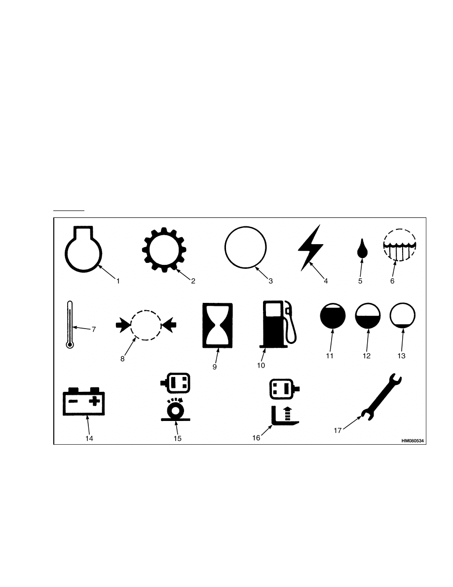
The meters and displays are used to provide oper-
ator information on the status of many systems in-
cluding: (1) engine coolant temperature, (2) engine
or transmission oil pressure or temperature, (3) fuel
level, (4) battery current (ammeter), battery voltage
(voltmeter), battery or state of charge (battery indi-
cators), (5) motor temperature, (6) motor brush wear,
(7) traction system status and (8) elapsed time. See
Figure 1, Figure 2, Figure 4, Figure 5, Figure 6, Fig-
ure 7, Figure 9 and Figure 10. However, every truck
or piece of equipment is not equipped with each one
of these meters.
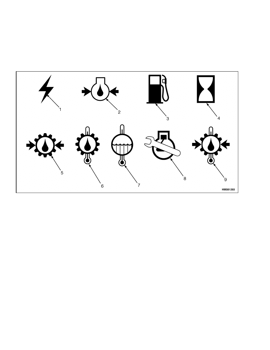
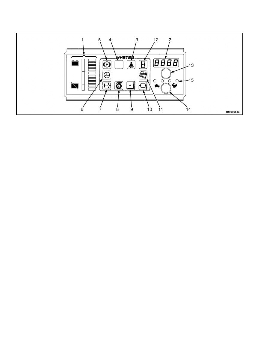
1.
ENGINE
2.
TRANSMISSION
3.
GENERATOR OR AMMETER
4.
CURRENT
5.
OIL
6.
WATER
7.
TEMPERATURE
8.
PRESSURE
9.
HOURS
10. FUEL
11. FUEL LEVEL - FULL
12. FUEL LEVEL - 1/2
13. FUEL LEVEL - EMPTY
14. BATTERY
15. BRUSH WEAR TRACTION
MOTOR
16. BRUSH WEAR LIFT MOTOR
17. MAINTENANCE
Figure 1. International Meter Face Symbols
1

Description
2200 SRM 143
Description
Many meters have meter-movements that move an
indicating needle attached to a shaft (or pin). The
shaft rotates to swing the needle when current flows
through the movement. The movement operates on
the same principle (electromagnetic) that rotates
a motor shaft. However, shaft rotation of a meter
is limited to much less than even one full revolu-
tion.
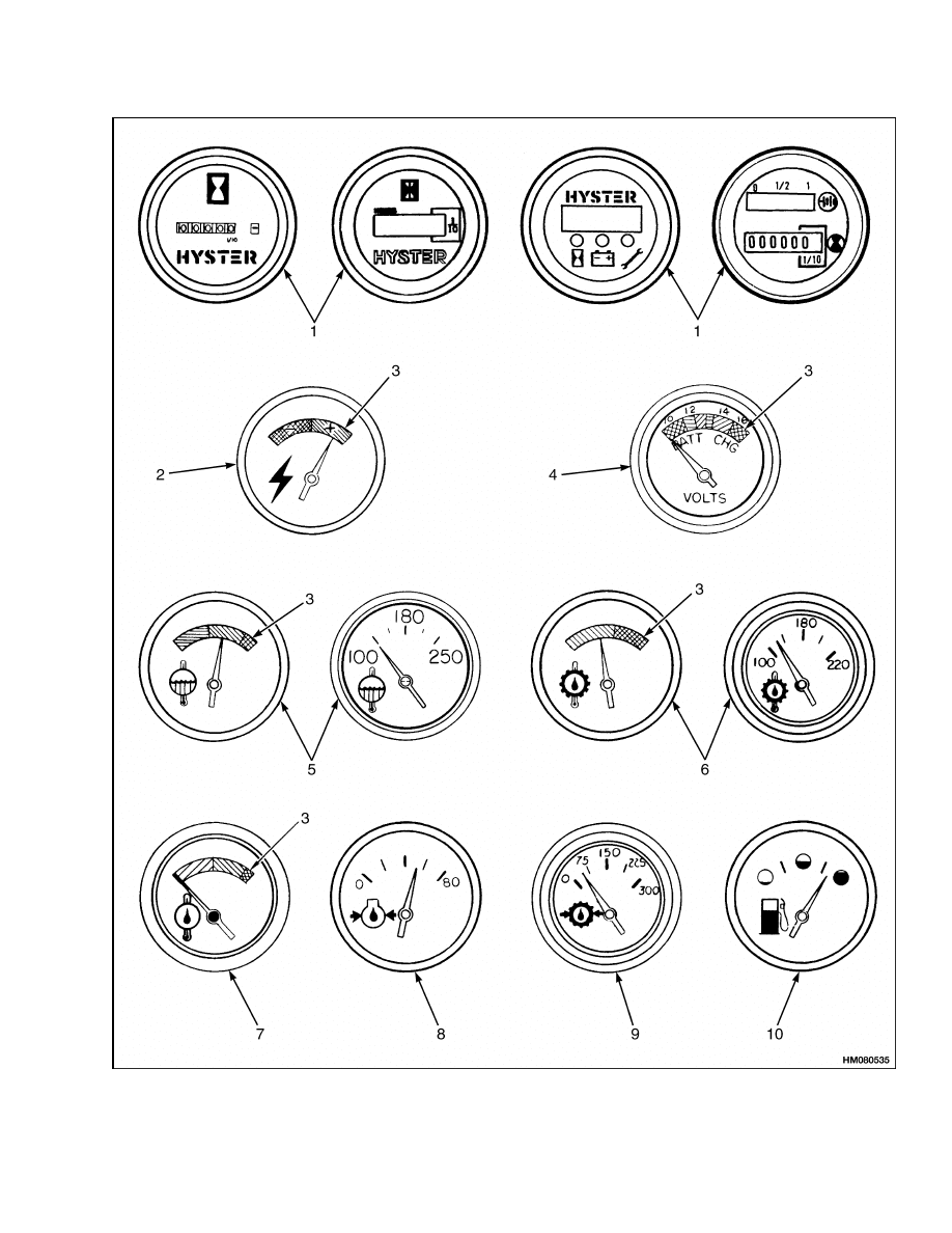
The amount of rotation or deflection of the
needle is directly related to the amount of current
flow through the meter-movement. Meter faces (or
scales) are calibrated to indicate a range of values
that are converted from a directly proportional cur-
rent flow through the sender.
See Figure 1 and
Figure 2 for some typical examples of meter faces
with various calibrations.
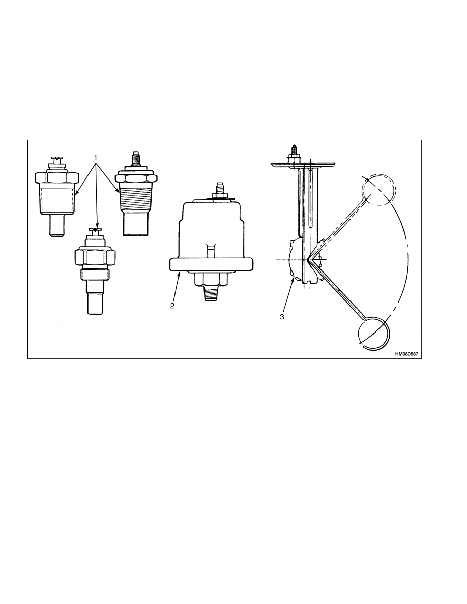
Meters such as ammeters, voltmeters and some
hourmeters, are able to convert this proportional
current within the meter case. Many other meters
and displays require a separate sender. See Figure 2.
Senders convert a specific pressure, temperature or
fluid level into a current flow that is directly related
to a given voltage (electrical system voltage) applied.
See Figure 3.
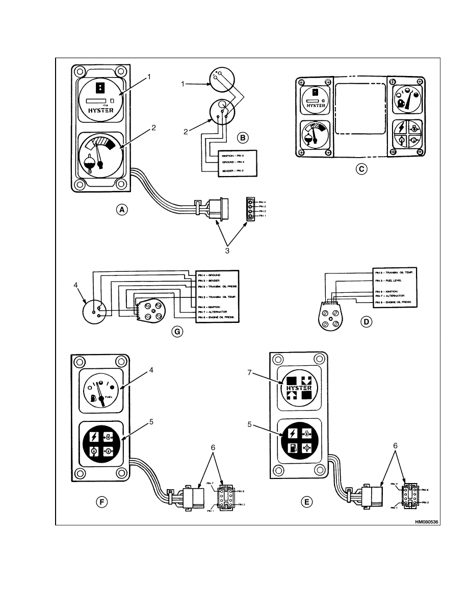
STEERING COLUMN GAUGES, METERS,
AND INDICATORS
Some lift trucks use a cluster of gauges, meters, and
indicator lights at the base of the steering column.
See Figure 4. The left side includes an hourmeter
and engine coolant temperature gauge. For diesel
and gasoline units, the right side has a fuel level
gauge. Below the fuel level gauge is a four function
indicator that has separate warning indicators for
the alternator, engine and transmission oil pressure,
and transmission oil temperature. For LPG units,
the fuel gauge is replaced by a bezel with the Hyster
emblem. The indicator with the gasoline pump sym-
bol will now indicate low LPG tank pressure. How-
ever, the optional pressure switch must be installed
in the LPG system. The indictor for oil pressure and
temperature (oil clutch units or powershift transmis-
sions) are combined in a two-function warning light
in the lower right position.
LED DISPLAY PANEL
Some lift trucks have a Light Emitting Diode (LED)
warning display on the instrument panel.
See
Figure 7, Figure 9, and Figure 10. The following
paragraphs describe how the circuit for each func-
tion operates and how to check its operation. The
LED warning display must be replaced as a complete
unit. The sensors for the LED warning display can
be replaced as separate parts.
Battery Discharge Indicators
NOTE: See the SRM section Battery Indicators
2260 SRM 138 for a more complete description of the
operation and the adjustment and repair procedures.
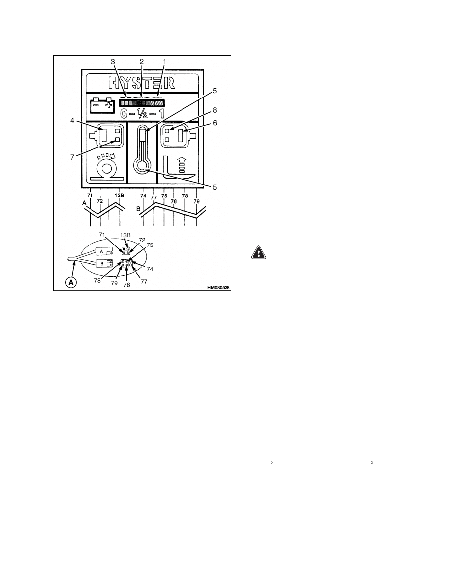
Earlier units without the LX control card have a
battery discharge indicator that is a scale with a
series of 10 LED’s of different colors. See (1, 2, and
3 of Figure 7. The LED’s illuminate in a sequence
(green, yellow, red) to indicate the discharge of the
battery as the battery voltage decreases during op-
eration. No more than two LED’s are illuminated at
one time. When the battery is fully charged, the two
green LED’s at the end of the scale are illuminated.
When the battery discharges during operation, the
illumination sequence moves to the left. The color
changes from green to yellow to red. When the bat-
tery is discharged to the red section of the battery
discharge indicator, the last two red LED’s begin to
flash just before the "lift interrupt" is enabled. When
the last two red LED’s are illuminated continuously,
the controller for the battery discharge indicator
stops the power to the hydraulic pump. This action
prevents the lift truck from lifting. Enough battery
power is normally available to move the lift truck
to a battery charger or to a place where a charged
battery can be installed.
2
2200 SRM 143
Description
Figure 2. Typical Meter Faces for Lift Trucks With Engines
3
Description
2200 SRM 143
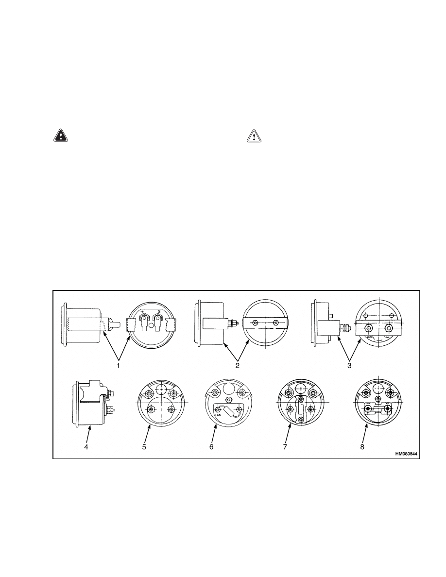
Legend for Figure 2
NOTE: METER FACE NUMBERS, INCREMENTS, AND COLORED BANDS CAN BE DIFFERENT THAN SHOWN.
1.
HOURMETER (ENGINE POWERED OR
ELECTRIC LIFT TRUCKS)
2.
AMMETER
3.
COLORED BANDS
4.
VOLTMETER
5.
ENGINE COOLANT TEMPERATURE
6.
TRANSMISSION OIL TEMPERATURE
7.
HYDRAULIC OIL TEMPERATURE
8.
ENGINE OIL PRESSURE
9.
TRANSMISSION OIL PRESSURE
10. FUEL LEVEL
1.
FLUID TEMPERATURE SENDERS
2.
FLUID PRESSURE SENDER
3.
FUEL LEVEL SENDER
Figure 3. Typical Senders for Lift Trucks With Engines
4
2200 SRM 143
Description
Figure 4. Typical Meters on Steering Column Assembly for Lift Trucks With Engines
5

Description
2200 SRM 143
Legend for Figure 4
A. LEFT HAND - ALL UNITS
B. WIRING DIAGRAM
C. GAUGES ON STEERING COLUMN
D. WIRING DIAGRAM
E. RIGHT HAND - LPG POWERED UNITS
F.
RIGHT HAND - DIESEL AND GASOLINE
POWERED UNITS
G. WIRING DIAGRAM
1.
HOURMETER
2.
ENGINE COOLANT TEMPERATURE GAUGE
3.
4-PIN CONNECTOR
4.
FUEL LEVEL GAUGE
5.
INDICATOR LIGHTS
6.
8-PIN CONNECTOR
7.
COVER WITH LOGO
6
2200 SRM 143
Description
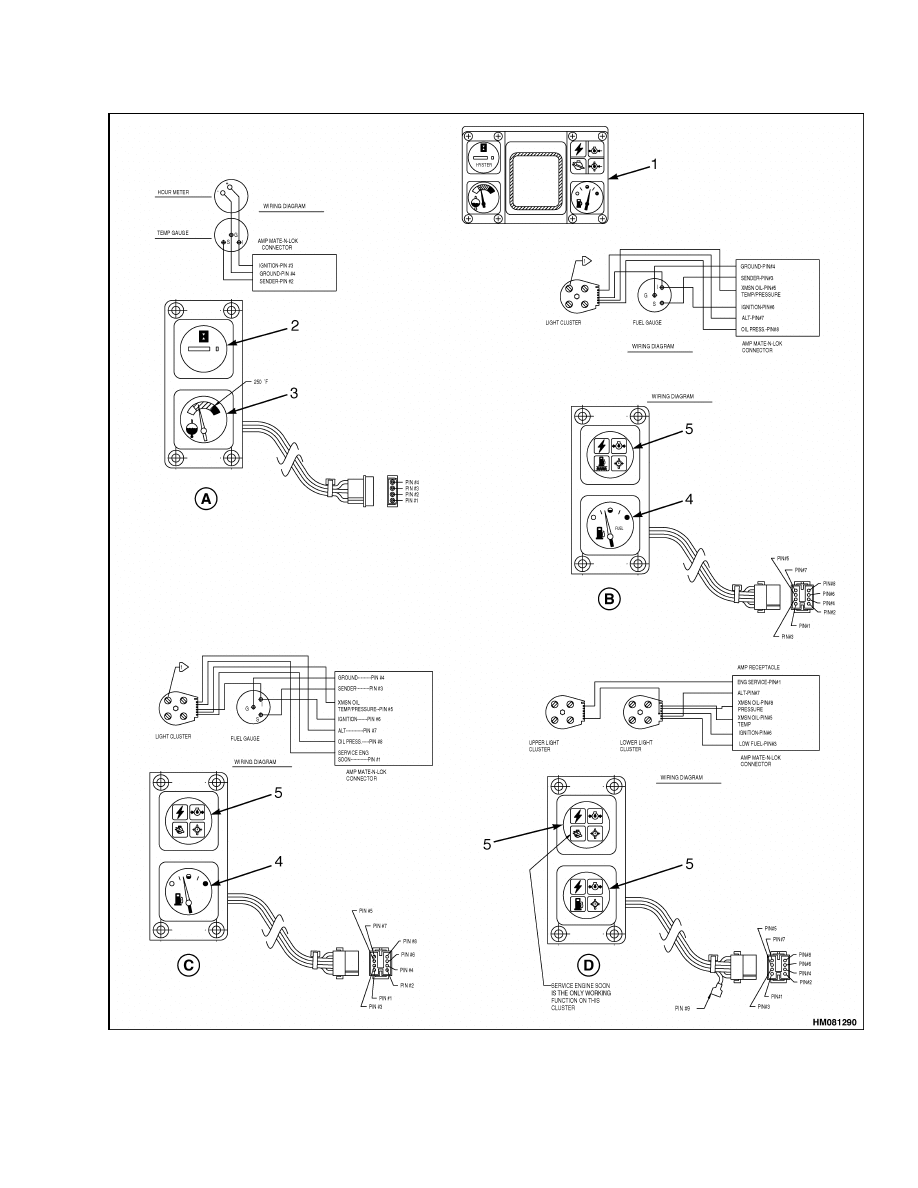
Figure 5. Steering Column Meters for H/S6.00-7.00XL (H/S135-155XL, S155XLS) (C024) (G006)
7
Description
2200 SRM 143
Legend for Figure 5
A. LEFT HAND - ALL UNITS
B. RIGHT HAND - DIESEL POWERED UNITS
C. RIGHT HAND GASOLINE POWERED UNITS
D. RIGHT HAND - LPG POWERED UNITS
1.
INSTRUMENT CLUSTER
2.
HOURMETER
3.
ENGINE COOLANT TEMPERATURE GAUGE
4.
FUEL LEVEL GAUGE
5.
INDICATOR LIGHTS
1.
ALTERNATOR INDICATOR
2.
ENGINE OIL PRESSURE
3.
FUEL LEVEL
4.
HOUR METER
5.
TRANSMISSION OIL PRESSURE
6.
TRANSMISSION OIL TEMPERATURE
7.
COOLANT TEMPERATURE
8.
CHECK ENGINE INDICATOR
Figure 6. Meter Face Symbols for H/S6.00-7.00XL (H/S135-155XL, S155XLS) (C024) (G006)
8
2200 SRM 143
Description
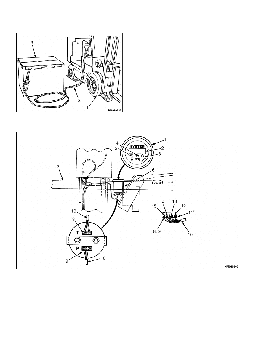
A. TO DISPLAY PANEL
1.
BATTERY INDICATOR LED, GREEN (3)
2.
BATTERY INDICATOR LED, YELLOW (4)
3.
BATTERY INDICATOR LED, RED (3)
4.
TEMPERATURE ALARM, TRACTION MOTOR
5.
TEMPERATURE ALARM, (ILLUMINATES WITH
4 OR 6)
6.
TEMPERATURE ALARM, HYDRAULIC MOTOR
7.
BRUSH WEAR INDICATORS, TRACTION
MOTOR
8.
BRUSH WEAR INDICATORS, HYDRAULIC
MOTOR
13. B - BATTERY POSITIVE
71. BATTERY NEGATIVE
72. BATTERY INDICATOR
74. TRACTION MOTOR TEMP.
75. TRACTION BRUSH WEAR
76. TRACTION BRUSH WEAR
77. PUMP MOTOR TEMP.
78. PUMP BRUSH WEAR
79. PUMP BRUSH WEAR
Figure 7. LED Display Panel (Some Earlier
Electric Lift Trucks)
Brush Wear Indicators
The brush wear indicators illuminate when the mo-
tor brushes must be replaced. The earlier units have
two indicators for the traction motor and two for the
pump motor. See Figure 7. The later display unit
has one indicator for each motor. See Figure 9 and
Figure 10. The sensor wires for the brush wear indi-
cators are an insert in the brush material when the
brush is made. The sensor wires are insulated from
the brush material. When the brush wears within
approximately 0.060 inch of the brush lead, the insu-
lation between the sensor wire and the brush mate-
rial is destroyed. The connection between the brush
and the sensor wire causes the indicator to illumi-
nate.
The operation of the brush wear indicators can be
checked during periodic maintenance. The battery
must be removed from the lift truck for access to the
motors. See Figure 8.
WARNING
Lift truck movement can cause an injury or
damage. Raise the drive wheels from the floor
to prevent lift truck movement. Use the cor-
rect procedure in the Operating Manual or the
section Periodic Maintenance of the Service
Manual to raise the drive wheels.
Use a jumper cable so that the battery can be con-
nected and still have motor access. Disconnect the
sensor wires, one at a time, from the outside of the
motor case. Touch the end of the sensor wire to bat-
tery negative. The LED indicator will illuminate if
the circuit is operating correctly. The motor brushes
must be replaced when they are worn. If equipped
with brush wear indicators, the condition of the com-
mutator and the motor brushes must still be checked
during periodic maintenance.
Motor Temperature Indicators
The traction motor and the hydraulic pump motor
have thermal switches inside the motors. See Fig-
ure 7 and Figure 9. When the temperature increases
to 300 F for Prestolite motors or 338 F for GE motors,
the thermal switch closes and the LED (ZX or earlier
units) on the instrument panel display illuminates.
This temperature is set by the manufacturer of the
motor and is below the temperature where the insu-
lation in the motor will have reduced life.
9
Description
2200 SRM 143
Figure 8. Connect Battery So Motor Can be
Operated
Legend for Figure 8
Connect the battery so that the motor can be
operated. The battery must be removed for access to
the motor. Use a jumper cable to connect the battery
to the lift truck. Raise the drive wheels. See "How
to Raise Drive Wheels" in the section Periodic
Maintenance for your lift truck or the Operating
Manual for your lift truck.
1.
RAISE DRIVE
WHEELS
2.
JUMPER
3.
BATTERY
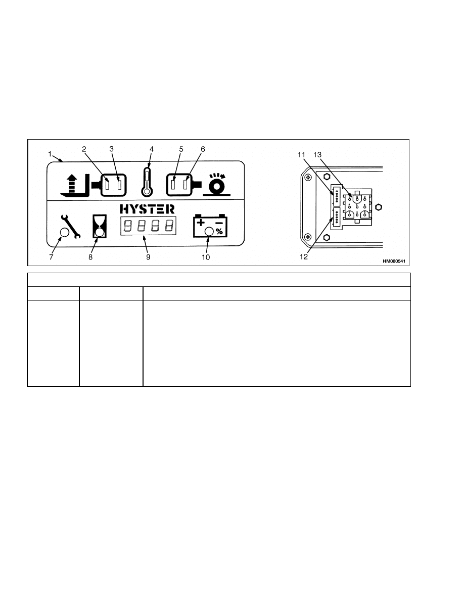
Figure 9. GE Instrument Panel Display and Plug Connector E40-60XL
10

2200 SRM 143
Description
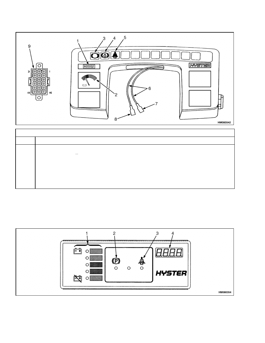
Legend for Figure 9
1.
DISPLAY UNIT
2.
FOUR DIGIT DISPLAY
3.
FUNCTION INDICATOR, STATUS CODE (GREEN
LED)
4.
FUNCTION INDICATOR, BATTERY (GREEN LED)
5.
FUNCTION INDICATOR, HOURMETER (GREEN
LED)
6.
MOUNT FOR DISPLAY UNIT
7.
INSTRUMENT PANEL
8.
CONNECTOR FOR MOTOR CONTROLLER,
TRACTION
9.
CONNECTOR FOR MOTOR CONTROLLER,
LIFT PUMP
10. TO CONTROL CARD PLUG Y
11. RED*
12. WHITE
13. GREEN
14. BARE
15. GREEN
*TRACTION CARD PLUG ONLY
WARNING
Lift truck movement can cause an injury or
damage. Raise the drive wheels from the floor
to prevent lift truck movement. Use the cor-
rect procedure in the Operating Manual or the
section Periodic Maintenance of the Service
Manual to raise the drive wheels.
The operation of the motor temperature indicators
can be checked during periodic maintenance. The
battery must be removed from the lift truck for access
to the motors. See Figure 8.
Use a jumper cable so that the battery can be con-
nected and still have motor access. Disconnect the
sensor wires from the outside of the motor case.
Touch the ends of the sensor wires together. The
LED indicator will illuminate if the circuit is oper-
ating correctly. The thermal switch can be replaced
if it has a malfunction. However, the motor must be
disassembled to replace the thermal switch.
LX SERIES DISPLAY PANEL
WARNING
Some adjustments can cause the lift truck to
operate differently than normal. This different
operation of the truck can result in personal
injury or damage. Do NOT try to make adjust-
ments for the instrument panel display with-
out using the procedures in the section EV-100/
200 LX Series Diagnostic Motor Controller and
Handset 2200 SRM 460.
There are two instrument panel displays used on
some electric lift trucks that have the EV-100/200
"LX" series control cards.
Both instrument panel
displays are shown in Figure 9 and Figure 10. These
instrument panel displays are optional on some
electric lift trucks with the EV-100 or EV-200 LX
series motor controller.
The early unit has a four digit display and three LED
function indicators. The indicators show which func-
tion value is displayed by the digits. Not all func-
tions are available on all lift truck models. Follow-
ing is a list of the functions: Battery Indicator, Sta-
tus Codes, Traction Hourmeter and Pump Hourme-
ter. Later units have the same digital display and
the same function indicators with the additional mo-
tor brush wear indicator and temperature alarm in-
dicator LED’s.
The following paragraphs describe how the circuit for
each function operates. The display panel must be
replaced as a complete unit. The sensors for brush
wear and motor temperature can be replaced as sep-
arate parts.
The digits show the operating hours when the
hourmeter function indicator is ON. When the bat-
tery indicator is ON, the digits show the charge
condition of the battery. See Figure 9 and Figure 10.
The status code indicator is ON when the digits show
the status code number. The brush wear or tempera-
ture alarm indicators of the later units will be ON if
the traction or pump motor brushes are too worn or
the motor is too hot. Refer to the descriptions Brush
Wear Indicators and Motor Temperature Indicators
for a complete description of the operation of these
indicators.
Hourmeter Functions
The hourmeter function on the instrument panel
display is controlled by the EV-100/200 "LX" series
control card. There can be a display for the oper-
ating time of the traction circuit. On some units,
there can also be a display for the operating time
of the pump circuit. Only those units that have the
EV-100LXP pump control card can have the optional
pump hourmeter function.
11
Description
2200 SRM 143
The instrument panel display shows the operating
time of 0000 to 9999 hours. The traction time is dis-
played for four seconds after the lift truck has been
operating and the key is turned to the OFF position.
If there is a pump hourmeter, the pump time will now
be displayed for another four seconds.
Battery Indicator Function
NOTE: See the SRM section Battery Indicators
2260 SRM 138 for a more complete description of the
operation and the adjustment and repair procedures.
The battery indicator reading is displayed on the four
digit display when the green function indicator above
the battery symbol is ON. See Figure 9 and Figure 10.
9-Pin Connector Wiring
Pin No.
Wire No.
Connection/Function
1
2
3
4
5
6
7
8
9
95
96
93
94
98
99
-
13
10
Traction Motor Temperature
Pump Motor Temperature
Traction Motor Brush (A) Wear
Traction Motor Brush (B) Wear
Pump Motor Brush (A) Wear
Pump Motor Brush (B) Wear
Not Used
Battery Negative
Battery Positive from Key Switch
1.
DISPLAY UNIT
2.
BRUSH WEAR INDICATOR, HYDRAULIC
MOTOR (YELLOW LED)
3.
TEMPERATURE ALARM, HYDRAULIC MOTOR
(RED LED)
4.
TEMPERATURE ALARM (RED LED)
(ILLUMINATES WITH 3 OR 5)
5.
TEMPERATURE ALARM, TRACTION MOTOR
(RED LED)
6.
BRUSH WEAR INDICATOR, TRACTION MOTOR
(YELLOW LED)
7.
STATUS CODE FUNCTION INDICATOR (GREEN
LED)
8.
HOURMETER FUNCTION INDICATOR (GREEN
LED)
9.
FOUR DIGIT DISPLAY
10. BATTERY FUNCTION INDICATOR (GREEN LED)
11. CONNECTOR, HYDRAULIC PUMP CARD
12. CONNECTOR, TRACTION CARD
13. 9-PIN MOTOR CONNECTOR
Figure 10. ITW Instrument Panel Display E40-60XL
12

2200 SRM 143
Description
This battery indicator uses the traction control shunt
to measure the current during operation. This cur-
rent and battery voltage are checked at the same
time for an accurate reading of battery voltage with
a load (during use). This method of checking voltage
and current is much more accurate than other meth-
ods used by battery indicators on earlier lift trucks.
This method allows more usage of the battery. Lift
truck operation can be different than with other bat-
tery indicators when a battery is low or a different
battery is connected.
The battery indicator function shows the battery
charge by the numbers between 0 and 100.
The
digital display will flash when the display reads 19.
At a display of 9 (80% discharged), the control will
disable the lift pump circuit. After the circuit has
disabled the lift pump, charge or change the battery.
The control also checks the battery voltage each time
a battery is connected. The traction control will pre-
vent lift truck operation if the battery voltage is not
correct as set by the traction function of the control
card. A status code of -16 (voltage too high) or -15
(voltage too low) will show on the instrument panel
display. The battery can have a voltage that is too
high or too low. A battery with the correct voltage can
also be over discharged from use or other reasons and
have a voltage that is less than the minimum voltage
range.
Status Code Function
The status codes are code numbers for different
symptoms that the control card can sense. The con-
trol card will show this code number on the digital
display. The control card will flash the status code
on the display. Every third display will show the
battery charge instead of the status code.
NOTE: See the section EV-100/200 LX Series Diag-
nostic Motor Controller and Handset 2200 SRM
460 for a description of the different status code dis-
plays.
ZX SERIES DISPLAY PANELS
Display Panel
WARNING
Some adjustments can cause the lift truck to
operate differently than normal. This different
operation of the truck can result in personal
injury or damage. Do NOT try to make adjust-
ments for the instrument panel display with-
out using the procedures in the section EV-100/
200ZX Motor Controller Parameter Tables 2200
SRM 595.
There are two display panels available on lift trucks
with the EV-100ZX SCR motor controller. The lift
trucks can only have one of the two display panels:
• a basic display that gives the operator basic infor-
mation about the operation of the lift truck
• a performance display that includes diagnostic ca-
pabilities similar to the Handset.
Basic Display Panels
The EV-100 "ZX" Series motor controller can have
two Basic display panels that include one of two types
of Battery Indicators. See Figure 11 and Figure 12.
13
Description
2200 SRM 143
Standard Display 18-Pin Connector
Pin
Function
1-11
12
13
14
15
16
17
18
No Connection
Battery Negative ( )
Parking Brake Switch
Brake Fluid Switch
Hyd. Contactor Coil
Seat Switch
Key Switch (IGN)
Battery Positive (+) (from Fuse 6)
1.
HOURMETER
2.
BATTERY METER
3.
PARKING BRAKE INDICATOR
4.
BRAKE FLUID TOO LOW INDICATOR
5.
SEAT BELT INDICATOR
6.
KEY SWITCH LEADS
7.
RED/BRN IGN TERMINAL
8.
BRN BAT TERMINAL
9.
18-PIN CONNECTOR
Figure 11. Basic (Early) Display Panel for EV-100/200ZX Motor Controllers
Figure 12. Basic (Later) Display Panel for EV-100/200ZX Motor Controllers
14

2200 SRM 143
Description
Legend for Figure 12
1.
BATTERY DISCHARGE INDICATOR
2.
PARKING BRAKE SYMBOL AND LED
3.
FASTEN SEAT BELT SYMBOL AND LED
4.
DIGITAL DISPLAY
EARLY DISPLAY PANEL
When the key is turned to the ON position, a start
program will cause each warning light to illuminate
to show that the function is operating. This later
display panel has the following functions:
(1) Hourmeter. The hourmeter display shows the
operating time of 0000 to 9999 hours. The time for
the traction circuit is shown for four seconds after the
lift truck has been operating and the key is turned to
the OFF position.
(2) Voltmeter. The earlier Basic Display Panel has
a battery indicator without lift interrupt (voltmeter).
This meter has a green, yellow and red band on the
meter face to indicate the voltage of the battery. The
needle starts in the green band with a fully charged
battery and moves to the red band as the battery
discharges. The battery must have a current draw
(load) to check the battery charge. Hold the tilt lever
in the tilt BACKWARD position or for the N30XMH,
hold the rotate lever in the ROTATE position and
look at the indicator. If the needle is in the red band,
charge the battery. Operating the lift truck with the
needle in the red band can decrease battery life. Con-
tinued operation with a discharged battery can dam-
age the battery, motors or the contactors.
(3) Warning light, parking brake indicator. The
red light is ON when the parking brake is applied
and the seat switch is closed, and goes OFF when the
parking brake is released.
(4) Warning light, brake fluid reservoir is low
(Early Only). The red light is ON for one second
when the key is turned to the START position and
must go OFF after one second. If the warning light
is ON during operation, the brake fluid level in the
reservoir is too low.
(5) Warning light, fasten seat belt. The red light
is ON for eight to ten seconds after the key is turned
to the ON position.
LATER DISPLAY PANEL
When the key is turned to the ON position, a start
program will cause each warning light to illuminate
to show that the function is operating. This later
display panel has the following functions:
(1) Battery Charge Indicator With Lift Inter-
rupt.
Later Basic display panels have a battery
indicator that is a scale with a series of 5 round
LEDs in three colors (green, orange, red). See Fig-
ure 12. There are two green LEDs and bars at the
top, two orange LEDs and bars in the center and
a red LED and bar at the bottom. As the battery
voltage decreases during operation, different LEDs
illuminate to indicate a discharged battery. No more
than two LEDs are illuminated at one time. When
the battery is fully charged, the two green LEDs
of the scale are illuminated. When the battery dis-
charges during operation, the LEDs illuminate from
top to bottom (green to red). The red LED indicates
that the battery is discharged. The battery must
be charged or a charged battery must be installed
before lift truck operation can continue.
The battery charge indicator uses the traction control
shunt to measure the current during operation. This
current and battery voltage are checked at the same
time for an accurate reading of battery voltage with
a load (during use). This method can make operation
of the lift truck different when the battery is low or a
different battery is connected. This method permits
better use of the battery charge.
The controller also checks the battery voltage each
time a battery is connected. The traction control will
prevent lift truck operation if the battery voltage is
not correct as set by traction function 15. A status
code of -16 (voltage too high) or -15 (voltage too low)
will indicate on the display panel. The battery can
have a voltage that is too high or too low. A battery
with the correct voltage can also be deeply discharged
from use or other reasons and have a voltage that is
less than the minimum of the voltage range.
Batteries that have different ampere hour ratings or
are of different ages can sometimes be used in the
same lift truck. It can be necessary to adjust trac-
tion Function 14 so that the weakest battery is not
damaged. Follow the procedure for adjusting trac-
tion Function 14 in the Checks And Adjustments.
(2) Warning light, parking brake indicator. The
red light is ON when the parking brake is applied
and the seat switch is closed, and goes OFF when the
parking brake is released.
15

Description
2200 SRM 143
(3) Warning light, fasten seat belt. The red light
is ON for eight to ten seconds after the key is turned
to the ON position.
(4) Digital Display. This indicator is blank when
the lift truck is operating correctly. The status codes
and the hourmeter values are shown on this four-
digit LCD display. When a fault occurs, the status
code will be shown with a dash ( ) in the left digit
position. The warning light, Service Interval (11) will
also be illuminated when a fault occurs.
When it is time for periodic maintenance, the warn-
ing light, Service Interval (11) will be illuminated
and a status code -99 will be indicated. The regis-
ter in the controller card must be reset by the service
person before this warning light will go OFF.
The hourmeter display shows the operating time of
0000 to 9999 hours. The time for the traction circuit
is shown for four seconds after the lift truck has been
operating and the key is turned to the OFF position.
The indicator lights for the traction motor (8) and for
the hourmeter (12) will also be illuminated during
this time. If there is an SCR control card for the hy-
draulic pump motor, this time will then be shown on
the hourmeter for another four seconds. The indi-
cator lights for the hydraulic motor (9) and for the
hourmeter (12) will also be illuminated during this
time.
Performance Display
When the key is turned to the ON position, a start
program will cause each warning and indicator light
to illuminate to show that the function is operating.
The functions and operation of the indicators for
these early and later display panels is the same. See
Figure 13 and Figure 14. These display panels have
the following functions:
(1) Battery Charge Indicator With Lift Inter-
rupt.
This battery charge indicator shows the
battery charge with an LED bar graph. There are
four green bars, four orange bars, and two red bars.
When the battery is discharged during operation, the
LED bar that is illuminated decreases sequentially
from the top green bar through the orange bars to
the red bars. When the battery is discharged to the
red LED bars, the battery is 73% discharged and the
lift interrupt function will not permit operation of
the hydraulic motor. The battery must be charged
or a charged battery must be installed before lift
truck operation can continue. The top green bar will
be illuminated when the battery is more than 90%
charged.
The battery charge indicator uses the traction control
shunt to measure the current during operation. This
current and battery voltage are checked at the same
time for an accurate reading of battery voltage with
a load (during use). This method can make operation
of the lift truck different when the battery is low or a
different battery is connected. This method permits
better use of the battery charge.
The controller also checks the battery voltage each
time a battery is connected. The traction control will
prevent lift truck operation if the battery voltage is
not correct as set by traction function 15. A status
code of -16 (voltage too high) or -15 (voltage too low)
will indicate on the display panel. The battery can
have a voltage that is too high or too low. A battery
with the correct voltage can also be deeply discharged
from use or other reasons and have a voltage that is
less than the minimum of the voltage range.
Batteries that have different ampere hour ratings or
are of different ages can sometimes be used in the
same lift truck. It can be necessary to adjust trac-
tion Function 14 so that the weakest battery is not
damaged. Follow the procedure for adjusting trac-
tion function 14 in the Checks And Adjustments.
(2) Digital Display. This indicator is blank when
the lift truck is operating correctly. The status codes
and the hourmeter values are shown on this four-
digit LCD display. When a fault occurs, the status
code will be shown with a dash ( ) in the left digit
position. The warning light, Service Interval (11) will
also be illuminated when a fault occurs.
The hourmeter display shows the operating time of
0000 to 9999 hours. The time for the traction circuit
is shown for four seconds after the lift truck has been
operating and the key is turned to the OFF position.
The indicator lights for the traction motor (8) and for
the hourmeter (12) will also be illuminated during
this time. If there is an SCR control card for the hy-
draulic pump motor, this time will then be shown on
the hourmeter for another four seconds. The indi-
cator lights for the hydraulic motor (9) and for the
hourmeter (12) will also be illuminated during this
time.
16
2200 SRM 143
Description
Enhanced Display 18-Pin Connector
Pin
Function
1
2
3
4
5
6
7
8
9
10
11
12
13
14
15
16
17
18
Traction Card PY 5
Pump Card PY 5
No Connection
Traction Card PY 14
Traction Card PY 13
Pump Card PY 14
Pump Card PY 13
No Connection
Traction Card PY 4
Pump Card PY 4
Brush Wear Indicator & Temperature Jumper*
*
Parking Brake Switch
Brake Fluid Switch
No Connection
No Connection
Key Switch (IGN)
No Connection
*Pin 11 to 12 Jumper (In Wire Harness). BWI and Temperature LED’s Disabled if Cut.
1.
BATTERY DISCHARGE INDICATOR
2.
DIGITAL DISPLAY
3.
FASTEN SEAT BELT INDICATOR
4.
BRAKE FLUID TOO LOW INDICATOR
5.
PARKING BRAKE INDICATOR
6.
STEERING PUMP MOTOR INDICATOR
7.
BRUSH WEAR INDICATOR
8.
TRACTION MOTOR INDICATOR
9.
LIFT PUMP MOTOR INDICATOR
10. MOTOR TEMPERATURE INDICATOR
11. STATUS CODE/MAINTENANCE INDICATOR
12. HOURMETER INDICATOR
13. STATUS CODE BUTTON
14. PERFORMANCE LEVEL BUTTON
15. PERFORMANCE LEVEL LEDS
16. KEY SWITCH LEADS
17. RED/BRN IGN TERMINAL
18. BRN BAT TERMINAL
19. 18-PIN CONNECTOR
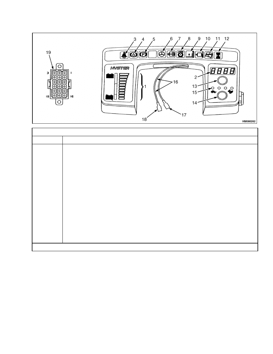
Figure 13. Early Performance Display Panels for EV-100/200ZX Motor Controllers
17
Description
2200 SRM 143
1.
BATTERY DISCHARGE INDICATOR
2.
DIGITAL DISPLAY
3.
FASTEN SEAT BELT INDICATOR
4.
BRAKE FLUID TOO LOW INDICATOR
5.
PARKING BRAKE INDICATOR
6.
STEERING PUMP MOTOR INDICATOR
7.
BRUSH WEAR INDICATOR
8.
TRACTION MOTOR INDICATOR
9.
LIFT PUMP MOTOR INDICATOR
10. MOTOR TEMPERATURE INDICATOR
11. STATUS CODE/MAINTENANCE INDICATOR
12. HOURMETER INDICATOR
13. STATUS CODE BUTTON
14. PERFORMANCE LEVEL BUTTON
15. PERFORMANCE LEVEL LEDS
Figure 14. Later Performance Display Panels for EV-100/200ZX Motor Controllers
(3) Warning Light, Fasten Seat Belt. The red light
is ON for eight to ten seconds after the key is turned
to the ON position.
(4) Warning Light, Brake Fluid Reservoir Is
Low (Early Only). The red light is ON for one sec-
ond when the key is turned to the START position
and must go OFF when the key is in the ON position.
If the warning light is ON when the key is in the ON
position, the brake fluid level in the reservoir is too
low.
(5) Warning Light, Parking Brake Indicator.
The red light is ON when the parking brake is ap-
plied and the seat switch is closed, and goes OFF
when the parking brake is released.
A warning buzzer will make a noise if the operator
leaves the seat (key moved to ON position) and the
parking brake is not applied.
(6) Indicator Light, Steering Pump Motor. This
light will illuminate with another warning light if a
fault occurs in the steering pump motor. If the brush
wear sensor is activated in the motor, the warning
light, brush wear (7) will go ON and the indicator
light for the steering pump motor will show which
motor has the problem.
(7) Warning Light, Motor Brushes Are Worn.
When the sensor for brush wear closes, this warning
light and the indicator light for the motor that has
the problem will both illuminate.
(8) Indicator Light, Traction Motor. This light
will illuminate with another warning light if a fault
occurs in the traction motor. Example: If the brush
wear sensor is activated in the motor, the warning
light, brush wear (7) will go ON and the indicator
light for the traction motor will show which motor
has the problem.
(9) Indicator Light, Hydraulic Motor. This light
will illuminate with another warning light if a fault
occurs in the hydraulic pump motor. Example: If the
temperature over limit switch closes in the motor, the
warning light, motor temperature over limit (10) will
go ON and the indicator light for the hydraulic motor
will show which motor has the problem.
(10) Warning light, Motor Temperature Over
Limit. The traction motor and the hydraulic pump
motor have thermal switches inside the motors.
When the temperature increases to the limit set by
the manufacturer of the motor, the thermal switch
closes and the warning light on the display panel
illuminates. The indicator light for traction motor
18

2200 SRM 143
Description
(8) or for the hydraulic motor (9) will show which
motor has the problem.
(14, 15) Set Lift Truck Performance.
The lift
truck can be set to four performance levels by the
operator. (If the customer does not want this func-
tion available to the operator, a service person can
set all four levels to the same setting.) Each time the
operator pushes the button (14), performance level
will increase by one step. At the maximum (rabbit)
level, the performance levels will begin at the lowest
(turtle) level again. The four performance levels set
by the manufacturer are:
1.
Low performance for handling fragile loads.
2.
Medium speed for less consumption of battery
charge during a work shift.
3.
Higher performance with higher consumption of
battery charge during a work shift.
4.
Maximum lift truck performance with maximum
consumption of battery charge.
The performance settings can be made with either
the PC or the Handset (Functions 11, 12, and 13).
The four performance levels can be set to any level up
to the maximum limits. Two or more adjacent per-
formance levels can be set to the same limits. The
performance levels must be set at the same or in as-
cending order (from turtle to rabbit). The register
interlocks will not permit a higher performance level
setting toward the turtle than the adjacent registers
toward the rabbit.
Fault Code Memory. The control cards for the trac-
tion motor controller and hydraulic pump motor each
have memory registers in which the last 16 status
codes can be stored. Each status code is stored with
the hourmeter time and the battery charge at the
time of the fault. The status code for the last fault
will be indicated on the Status Code Indicator (2). If
the key is turned to OFF, the status code will be re-
moved from the four digit display.
The push button (13) will cause the status codes for
the for the faults to be shown on the Status Code Indi-
cator (2). When the button is pushed and held down,
the indicator light for the traction motor (8) will illu-
minate. The status codes in memory for the detected
faults will be displayed, starting with the most re-
cent fault. If the push button is released, the display
will stop. If the button is pushed again, the display
will start from the beginning again. The hourmeter
time and the battery charge at the time of the fault
will not be shown. A Handset or a PC must be used
to show this additional information. A Handset or
a PC must be used to clear the status code from the
register.
If the button is pushed twice and then held down,
the indicator light for the hydraulic pump motor (9)
will illuminate. The status codes in memory for the
detected faults will be displayed, starting with the
most recent fault. If the push button is released, the
display will stop. If the button is pushed twice to
start the sequence again, the display will start from
the beginning. The hourmeter time and the battery
charge at the time of the fault will not be shown. A
Handset or a PC must be used to show this additional
information. A Handset or a PC must be used to clear
the status code from the register.
There can be 16 status codes in the memory for each
system (traction or lift). Push and hold the push but-
ton to display all the status codes in the memory for
detected faults of the traction system. The Traction
Motor Indicator will be ON to show that the status
codes are for the traction system. If the push button
is released then pushed and held again, the digital
display will start over showing all the status codes
for the traction system. Push the button twice and
hold the push button to display all the status codes
in the memory for detected faults of the lift system.
The Lift Pump Motor Indicator will be ON to show
that the status codes are for the lift system. If the
push button is released then pushed twice and held
again, the digital display will start over showing all
the status codes for the lift system.
Brush Wear Indicators
The brush wear indicators illuminate when the mo-
tor brushes must be replaced. The sensor wires for
the brush wear indicators are an insert in the brush
material when it is made. The sensor wires are in-
sulated from the brush material. When the brush
wears within approximately 0.060 inch of the brush
lead, the insulation between the sensor wire and the
brush material is destroyed. The connection between
the brush and the sensor wire causes the indicator to
illuminate.
The operation of the brush wear indicators can be
checked during periodic maintenance. The battery
must be removed from the lift truck for access to the
motors.
19

Replacement - General Information
2200 SRM 143
Adjustments - General
There are no adjustments to perform except for some
battery indicators.
Refer to Battery Indicators
2260 SRM 138 to adjust the battery indicators. Re-
fer to EV-100/200 LX Series Diagnostic Motor
Controller and Handset 2200 SRM 460 to adjust
the I.T.W. display panel.
Replacement - General Information
WARNING
Before replacing any components, fully lower
all parts of the mast and tilt it forward until the
tips of the forks touch the ground. This action
will prevent the mast from lowering suddenly
if the control lever is accidently moved.
ALWAYS disconnect the battery and remove
the key before replacing components.
Never have any metal on your fingers, arms or
neck. These metal items can accidentally make
an electrical connection and cause an injury.
NOTE: None of the electrical components of this sec-
tion can be repaired. All bad components must be
replaced.
Meters, display panels, most indicators and senders
are not repairable items. The most accurate and usu-
ally easiest checks for proper operation of individual
meters, indicators or senders is direct replacement.
The most common cause of failure is poor connec-
tions, or damaged or improper wiring and not the me-
ter indicator or sender. This section only has the re-
placement procedures. Before a meter, display panel,
indicator or sender is replaced, make the following
checks:
1.
Check that other meters and electrical circuits
operate correctly.
2.
Check that the battery is fully charged, has
a good ground (diesel, gasoline and LPG units
only) and the cable terminals are clean and tight.
3.
Check that the wiring and connections to the me-
ter, indicator or sender are tight and in good con-
dition.
20
2200 SRM 143
Meter Replacement
Meter Replacement
Meters are usually mounted to an instrument panel.
See Figure 15. Access to the back of the panel or
mounting surface is required for meter replacement.
Replace a meter as follows:
1.
Make sure the key is in the OFF position.
WARNING
Meters normally have voltage at the terminals.
A short circuit of this voltage can result in
meter damage or personal injury. To prevent
a short circuit during meter replacement,
disconnect the battery negative cable at the
battery negative terminal. Install a lock or tag
on the connector to prevent connection.
2.
Put tags on the meter wires for correct identifica-
tion during installation. Remove the wires from
the meter terminals.
NOTE: If the meter is illuminated, remove bulb
socket and bulb from the meter.
3.
Remove the nuts and washers that fasten the
mounting bracket to the meter housing.
4.
Remove the meter and install the replacement
meter in the panel. Make sure the meter is in
the correct position for reading by the operator.
5.
Install the mounting bracket, washers and nuts.
Tighten the nuts.
CAUTION
A short circuit and damage can occur if wires
are not installed correctly.
Make sure wire
connectors do not touch the other meter termi-
nals or wire connectors, metal brackets, or the
bracket mounting nuts. Make sure the wires
are not pulled tight and are not touching other
parts to damage the insulation.
6.
Connect the wires to the meter electrical termi-
nals. Tighten the nuts if the nuts are required
for correct connection.
NOTE: If the meter is illuminated, install the socket
with the bulb into the meter housing.
1.
HOURMETER
2.
AMMETER (FARIA)
3.
OIL TEMPERATURE (DATCON)
4.
(A.C.) METERS
5.
AMMETER
6.
VOLTMETER
7.
TEMPERATURE
8.
OIL PRESSURE AND FUEL LEVEL
Figure 15. Meters and Mount Brackets
21
Sender Replacement
2200 SRM 143
Sender Replacement
FUEL LEVEL SENDER
WARNING
All fuel vapors are extremely explosive. Do not
allow sparks or flames around vehicles or fuel
storage and service areas. Make sure there is
no source of open flame or sparks in the vicin-
ity. Use caution to prevent sparks from tools.
The fuel level sending unit is mounted to the fuel
tank surface (usually top surface) with screws
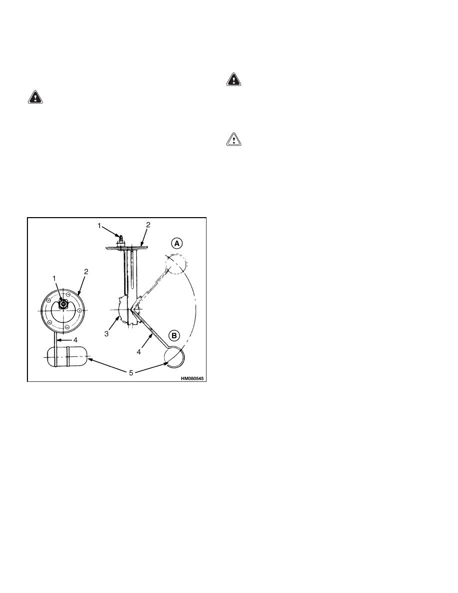
through the sender plate and gasket. See Figure 16.
Correct sender operation and screw hole alignment
can only be obtained with the plate mounted in one
position. Replace the sender as follows:
A. FULL POSITION
B. EMPTY POSITION
1.
ELECTRICAL
TERMINAL
2.
PLATE
3.
SENDER UNIT
4.
FLOAT ARM
5.
FLOAT
Figure 16. Fuel Level Sender
1.
Turn key switch to OFF position and disconnect
negative battery cable at battery. Install lock or
tag on connector to prevent connection.
2.
Disconnect sender wire at sender.
WARNING
Electrical shock from voltage can cause per-
sonal injury. Put electrical tape on the wire
connector to electrically insulate the connec-
tor if the wire is accidentally energized.
CAUTION
Fuel level senders are not accurate if the arm
is bent during removal and installation. There
must also be clearance for operation. Do not
bend the float arm.
3.
Remove screws that fasten sender plate to fuel
tank. Remove sender.
4.
Carefully install new sender with new gasket.
5.
Make sure screw holes are aligned and install
screws. Tighten screws enough to partially com-
press gasket to prevent leaks.
6.
Remove tape from wire connector. Install connec-
tor on sender terminal.
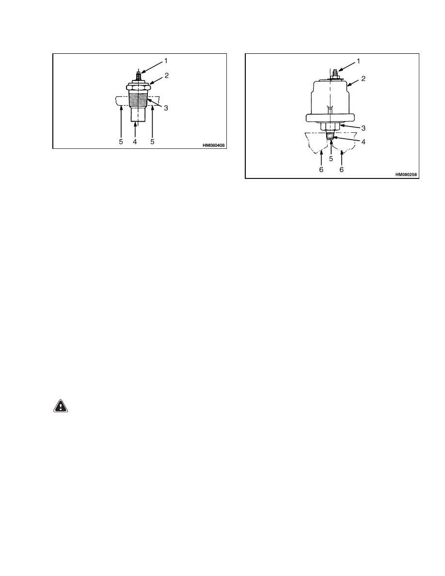
PRESSURE AND TEMPERATURE SENDER
Pressure senders have a hollow threaded fitting fas-
tened to the base. See Figure 17 and Figure 18. This
makes it possible for the sender to sense the pressure
and also to fasten the sender to the equipment. The
sender can be tightened or loosened using a wrench
on the flats of the hex shape of the fitting. The body of
the temperature sender has threads to fit a threaded
hole in the equipment. Replace either sender as fol-
lows:
NOTE: Make sure the system fluid is drained to a
level below the sender to prevent leakage when the
sender is removed.
1.
Turn key switch to OFF position.
2.
Disconnect sender wire.
3.
Turn sender counterclockwise with a wrench un-
til free. Remove and discard old sender.
4.
Install new sender and tighten with a wrench.
5.
Connect sender wire.
22
2200 SRM 143
ITW Display Panel Replacement
1.
ELECTRICAL TERMINAL
2.
HEX
3.
THREADED BODY
4.
SENSOR ELEMENT
5.
CASE OF ENGINE OR TRANSMISSION
Figure 17. Typical Pressure and Temperature
Sender
1.
ELECTRICAL TERMINAL
2.
SENDER
3.
HEX
4.
THREADED FITTING
5.
HOLE-TO-SENSOR ELEMENT
6.
CASE OF ENGINE OR TRANSMISSION
Figure 18. Fluid Pressure Sender
ITW Display Panel Replacement
REMOVE
The display panel is in the instrument panel. The
display panel cannot be repaired and must be re-
placed if it has a malfunction. See Figure 10.
1.
Move the lift truck to a safe, level area. Turn
the key to the OFF position and remove the key.
Put a DO NOT OPERATE tag on the steering
wheel. Put blocks under the drive wheels to keep
the lift truck from moving. See the section Peri-
odic Maintenance or the Operating Manual
for your lift truck to place the blocks.
WARNING
Disconnect the battery and separate the con-
nector before opening the compartment cover
or inspecting or repairing the electrical sys-
tem. If a tool causes a short circuit, the high
current flow from the battery can cause an
injury or parts damage.
2.
Disconnect and separate the battery connector.
3.
If installed, remove the cowl cover under the in-
strument panel.
4.
Install labels for correct connection during in-
stallation and disconnect all electrical plugs and
wires from the back of the display panel.
5.
Remove the screws or nuts that fasten the dis-
play panel assembly to the instrument panel.
Lift the display panel up out of the instrument
panel.
6.
Install the replacement display panel and install
the screws or nuts. Make sure the panel can be
read by the operator.
7.
Correctly connect all electrical plugs or wires ac-
cording to the labels made during removal.
8.
Remove the blocks from under the drive wheels,
remove the DO NOT OPERATE tag, connect the
battery, and install the key.
23
Column Mount Display Panel (EV-100/200ZX Motor Controllers) Replacement
2200 SRM 143
Column Mount Display Panel (EV-100/200ZX Motor
Controllers) Replacement
REMOVE
The display panel is in the instrument panel. The
display panel cannot be repaired and must be re-
placed if it has a malfunction. The display panels
must be replaced as a unit.
NOTE: Most parts of the column mounted display
panel can be replaced. However, the LED indicators
cannot be replaced separately. The LEDs are part
of the circuit board assembly. The major replace-
able parts of this display panel are: 1) key switch;
2) housing, top cover, and O-ring seal; 3) housing
and light filter for LED warning lights; 4) hourme-
ter and gasket; 5) battery indicator; 6) buzzer and
circuit board; and 7) jumper harness and the wires
to the key switch.
NOTE: The only replaceable parts of the Perfor-
mance display panel are the O-ring seal, key switch,
wires to the key switch, and the housing that fastens
to the steering column. All other parts of the panel
must be replaced as a single unit. See Display Panel
Assembly, Replace of this section.
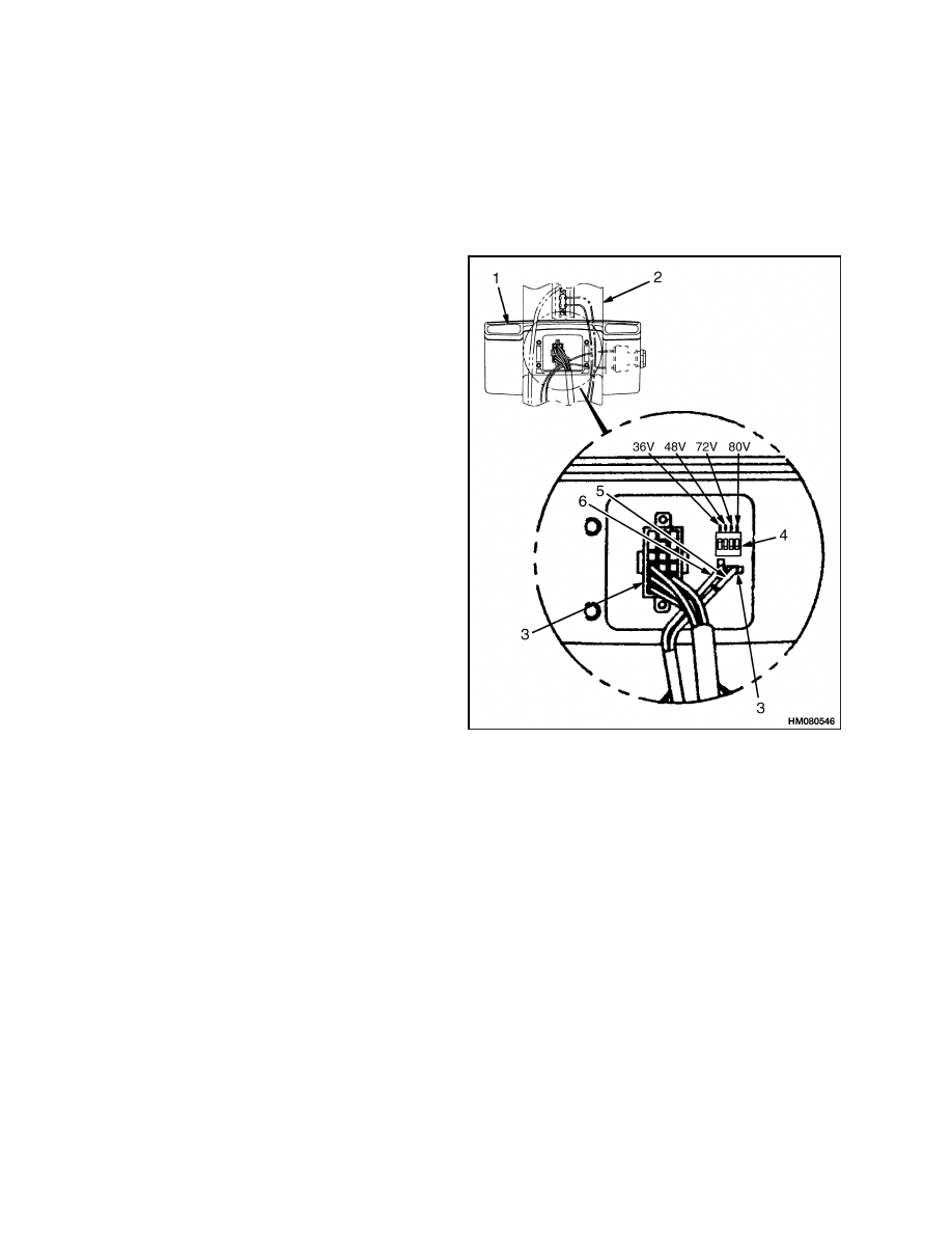
DISPLAY PANEL ASSEMBLY, REPLACE
Follow this procedure to replace the Basic or Perfor-
mance display panel as an assembly:
1.
Disconnect the battery and remove the key.
2.
Remove the front steering column cover with
the display panel assembly attached. Carefully
disconnect the 18-pin connector, the key switch
wires and, on the Basic panel, the two-pin con-
nector from inside the column cover.
3.
Remove the four screws that fasten the display
panel to the column cover.
4.
Install the replacement display panel assembly
to the cover of the steering column and tighten
the screws. Install the connectors and the key
switch wires. On the Basic panel, set the DIP
switches near the connector for the panel to the
voltage of the lift truck. See Figure 19. Move the
DIP switch for the correct voltage to the up posi-
tion and all others to the down position. Install
the column cover on the steering column.
NOTE: ON = UP AS SHOWN.
36V SW#1 ON, OTHERS OFF.
48V SW#2 ON, OTHERS OFF.
NOTE: SET DIP SWITCHES TO TRUCK VOLTAGE. IF
TRUCK VOLTAGE IS NOT KNOWN, SET 36/48V (U.S.)
TRUCKS TO 48V.
1.
DISPLAY PANEL
2.
STEERING
COLUMN
3.
ELECTRICAL
CONNECTOR
4.
DIP SWITCHES
5.
BROWN
6.
RED/BROWN
Figure 19. Dip Switches
24

2200 SRM 143
Column Mount Display Panel (EV-100/200ZX Motor Controllers) Replacement
INDICATOR LEDS
NOTE: The indicator LEDs of the Basic display
panel are part of the circuit board and must be
replaced as an assembly. See Basic Display Panel,
Replace Parts of this section. The LED indicators of
the Performance display panel cannot be replaced.
If these LED indicators are bad, replace the display
panel. See Display Panel Assembly, Replace of this
section.
BATTERY INDICATORS
There are two types of battery indicators for these
trucks. One type is a meter movement with colored
bands showing the battery charge (Basic display
panel). The other type is a Light Emitting Diode
(LED) display with LEDs of different colors showing
battery charge (Performance display panel).
NOTE: The battery indicator is replaced as one of the
components of the display panel. See procedure un-
der Basic Display Panel, Replace Parts of this sec-
tion. The battery indicator of the Performance dis-
play panel cannot be replaced as a separate compo-
nent. The indicator must be replaced as part of the
Performance display panel. See Display Panel As-
sembly, Replace of this section.
See the section Battery Indicators 2260 SRM 138
to adjust these battery indicators.
DIGITAL DISPLAY (PERFORMANCE
DISPLAY PANEL ONLY)
NOTE: The digital display of the Performance dis-
play panel cannot be replaced as a separate compo-
nent. The display must be replaced as part of the
Performance display panel. See Display Panel As-
sembly, Replace of this section.
STATUS CODE OR PERFORMANCE
LEVEL SWITCHES AND INDICATOR LEDS
(PERFORMANCE DISPLAY PANEL ONLY)
NOTE: These switches of the Performance display
panel cannot be replaced as separate components.
The switches must be replaced as part of the Perfor-
mance display panel. See Display Panel Assembly,
Replace of this section.
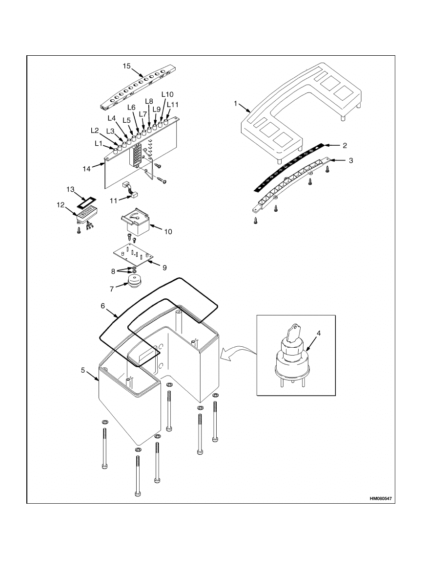
BASIC DISPLAY PANEL, REPLACE PARTS
NOTE: The parts of the Basic Display Panel can be re-
placed with the display panel on the steering column.
If the assembly housing will be replaced, remove the
complete assembly from the steering column as de-
scribed in Display Panel Assembly, Replace.
NOTE: The following is a complete disassembly pro-
cedure. Do ONLY those steps necessary to replace
the part you want replaced.
Remove and replace the components of the Basic dis-
play panel as follows:
1.
Disconnect the battery and remove the key.
2.
Remove the eight screws that fasten the top cover
to the panel housing. The screws are at the bot-
tom of the housing. See Figure 20. The hourme-
ter is fastened to the top cover with the electrical
connector on the circuit board inside the housing.
Carefully lift the top cover up off the housing and
the indicator LEDs without damaging the O-ring
gasket. The gasket for the LED indicators can
stick to the LED housing as the top cover is re-
moved. Do not lose or damage the gasket. Dis-
connect the three wire connector for the hourme-
ter.
3.
If the housing or filter for the indicators will be
replaced, remove the screws that fasten the LED
housing to the cover. If the hourmeter or hourme-
ter gasket will be replaced, remove the screws
that fasten it to the top cover. Install the replace-
ment parts to the top cover. Make sure that the
hourmeter is installed so that it can be read after
the cover is installed.
4.
Remove the nut that fastens the key switch. Re-
move the key switch from the housing. Make a
note of which wires are on which terminals and
disconnect the wires. Install the wires on the
same terminals of the replacement switch.
5.
Align the notch in the shaft housing of the key
switch with the tab in the housing of the display
panel. Install the replacement switch. Tighten
the nut and connect the wires.
25
Column Mount Display Panel (EV-100/200ZX Motor Controllers) Replacement
2200 SRM 143
Figure 20. Standard Display Panel
26

2200 SRM 143
Column Mount Display Panel (EV-100/200ZX Motor Controllers) Replacement
Legend for Figure 20
1.
TOP COVER
2.
FILTER FOR LED INDICATORS
3.
HOUSING FOR LED INDICATORS
4.
KEY SWITCH
5.
ASSEMBLY HOUSING
6.
O-RING GASKET
7.
BUZZER
8.
FIBER INSULATING WASHERS
9.
CIRCUIT BOARD (LH) FOR BATTERY
INDICATOR
10. BATTERY INDICATOR
11. JUMPER HARNESS
12. HOURMETER
13. GASKET FOR HOURMETER
14. CIRCUIT BOARD FOR LED INDICATORS
15. GASKET FOR LED INDICATORS
NOTE: It is not necessary to do Step 6 if only the
meter movement of the battery indicator will be re-
placed on the existing circuit board. Carefully lift the
meter movement up off the pins of the circuit board
without bending the pins. See Figure 20. Carefully
install the replacement meter movement on the pins.
Make sure the pins are correctly aligned on the back
of the meter before pushing the meter on the pins.
6.
If the battery indicator, circuit board for the
hourmeter or the buzzer will be replaced, re-
move the screws that fasten the circuit board
to the housing. Disconnect the connector from
the circuit board. Remove the buzzer from the
bottom of the circuit board. Make sure to install
the fiber washer when installing the replace-
ment buzzer on the replacement circuit board. If
necessary, carefully lift the meter movement up
off the pins of the circuit board without bending
the pins. See Figure 20. Carefully install the
replacement meter movement on the pins of the
replacement circuit board. Make sure the pins
are correctly aligned on the back of the meter
before pushing the meter on the pins. Connect
the electrical connector to the circuit board and
install the circuit board assembly in the housing.
7.
If the LED indicator assembly will be replaced,
first remove the 18-pin connector. It is neces-
sary to remove the front steering column cover
with the display panel assembly attached for ac-
cess to the connector. After removing the screws
that fasten the front cover, carefully disconnect
the connector. It can be necessary to disconnect
the key switch wires (Step 4) and the two wire
connector for enough clearance to disconnect the
18-pin connector. Remove the two screws that
fasten the LED assembly to the housing. Install
the replacement LED assembly, carefully con-
nect all connectors and wires. Install the front
steering column cover with the display panel as-
sembly attached. Install the LED gasket over the
LED indicators.
8.
If necessary, install a new O-ring gasket. Care-
fully install the O-ring gasket in the groove of
the top cover. Carefully install the top cover as-
sembly over the LED indicators and assembly
housing without damaging either the LED gas-
ket or O-ring gasket. Make sure the O-ring gas-
ket is still correctly aligned with the cover and
housing before installing the screws. Install the
eight screws that fasten the top cover to the panel
housing and tighten them in a cross pattern.
PERFORMANCE DISPLAY PANEL,
REPLACE PARTS
NOTE: The only replaceable parts of the Perfor-
mance display panel are the O-ring seal, key switch,
wires to the key switch and the housing that fastens
to the steering column. All other parts of the panel
must be replaced as a single unit. See Display Panel
Assembly, Replace of this section.
27
Specifications
2200 SRM 143
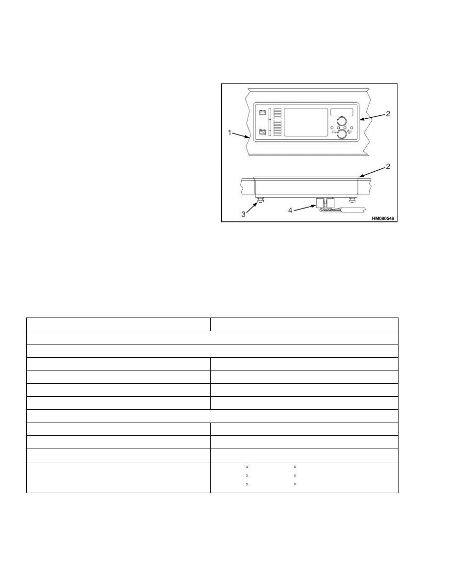
Dash Mount Display Panel (EV100/200ZX Motor
Controllers) Replacement
REMOVE AND REPLACE
The display panel is in the dash. See Figure 21. The
display panel cannot be repaired and must be re-
placed if it has a malfunction. These display panels
must be replaced as a unit.
1.
Disconnect the battery.
2.
Disconnect the plug connector on the back of the
display panel. Access is under the dash.
3.
Remove the four nuts that fasten the display
panel and lift it up out of the dash.
4.
Install the replacement display panel in the
dash.
5.
Install and tighten the nuts that fasten the dis-
play panel in the dash and install the plug con-
nector.
1.
DASH PANEL
2.
DISPLAY PANEL
3.
MOUNT NUTS
4.
PLUG
CONNECTOR
Figure 21. Dash Mount Display Panels
Specifications
METER SPECIFICATIONS
Item
Design Data
Operating Voltage
Hourmeter
Engine-Powered Equipment
12V, 24V
Electric Motor-Powered Equipment
12V, 24V, 36V, 48V, 72V, 80V or multiple 30 to 130V
All Other Meters
12V, 24V
Terminal Threads
#10-32 UNF or #6-32 UNC
Range of Meter
Hourmeter
0.0 to 9.999.9 Hours
Ammeter
0 to ±60 Amps
Voltmeter
10 to 16 Volts
Temperature Gauge (Range Based on Require-
ments)
38 to 104 C (100 to 220 F)
38 to 121 C (100 to 250 F)
38 to 182 C (100 to 360 F)
28
2200 SRM 143
Troubleshooting
Item
Design Data
Pressure Gauge (Range Based on Requirements)
0 to 552 kPa (0 to 80 psi)
0 to 1380 kPa (0 to 200 psi)
0 to 2068 kPa (0 to 300 psi)
Method of Mounting
To Panel with Bracket
SENDER SPECIFICATIONS
Item
Design Data
Operating Voltage
All Senders
12-Volt System
Terminal Threads (Electrical)
All Senders
#10-32 UNF-2A
Fastener Data (To Fit in a Threaded Hole)
Temperature Sender
Body Threads
1/2-14 Dryseal
Hex (Across Flats)
23.4 mm (0.92 in.) for a 15/16 in. Wrench
Pressure Sender
Fitting Threads
1/8-27 Dryseal NPTF
Hex (Across Flats)
22.4 mm (0.88 in.) for a 7/8 in. Wrench
Fuel Sender Plate
Number of Holes
5 (Not Equally Spaced)
Hole Size
5 - 5.1 mm (0.196 - 0.200 in.)
Troubleshooting
PROBLEM
POSSIBLE CAUSE
PROCEDURE OR ACTION
METER
No Indication - All Meters
Battery disconnected.
Clean the battery terminals and bat-
tery cable connectors. Install connec-
tors.
Battery malfunction or discharged.
Charge or replace battery.
Wiring group connector or connec-
tors not connected.
Fasten the connector or connectors.
29

Troubleshooting
2200 SRM 143
PROBLEM
POSSIBLE CAUSE
PROCEDURE OR ACTION
No Indication - Only One
Meter
Meter wires damaged or not con-
nected.
Replace the broken wires or connec-
tors. Install connectors on proper me-
ter terminals.
Separate sender wire damaged or
not connected.
Replace broken wire or connector. In-
stall connector on sender terminal.
Meter malfunction. Voltage is at ter-
minal.
Replace meter.
Sender malfunction.
Voltage is at
terminal.
Replace sender.
Incorrect Indication
Battery is discharged.
Charge battery.
Meter movement or needle is dam-
aged or has a malfunction.
Replace meter.
Separate sender malfunction.
Replace sender.
Sender will not sense because sys-
tem has corrosion.
Clean and flush system.
30


TECHNICAL PUBLICATIONS
2200 SRM 143
8/04 (12/03)(11/99)(3/99)(6/98)(9/96)(2/95)(5/91)(4/89)(1/79) Printed in United Kingdom
Document Outline
- toc
- Instrument Panel Indicators and Senders
- Safety Precautions Maintenance and Repair
- General
- Description
- Adjustments - General
- Replacement - General Information
- Meter Replacement
- Sender Replacement
- ITW Display Panel Replacement
- Column Mount Display Panel (EV-100/200ZX Motor Controllers) Repl
- Dash Mount Display Panel (EV100/200ZX Motor Controllers) Replace
- Specifications
- Troubleshooting
Wyszukiwarka
Podobne podstrony:
1578950 2200SRM1119 (08 2004) UK EN
1565183 2200SRM1110 (08 2004) UK EN
1538373 2200SRM1065 (02 2004) UK EN
1559550 2200SRM1097 (10 2004) UK EN
910030 1400SRM0047 (08 2004) UK EN
1494143 2200SRM0939 (12 2004) UK EN
1519772 2200SRM1016 (10 2004) UK EN
897495 2200SRM0514 (01 2004) UK EN
1566270 0100SRM1118 (08 2004) UK EN
1564268 2200SRM1106 (01 2004) UK EN
1565181 2000SRM1108 (08 2004) UK EN
897409 2200SRM0460 (08 1995) UK EN
1556871 2200SRM1105 (01 2004) UK EN
więcej podobnych podstron