INSTRUMENT PANEL
INDICATORS AND
SENDERS
H40.00-52.00XM-16CH
(H1050, 1150HD-CH) [E117]
PART NO. 1565183
2200 SRM 1110

SAFETY PRECAUTIONS
MAINTENANCE AND REPAIR
• When lifting parts or assemblies, make sure all slings, chains, or cables are correctly
fastened, and that the load being lifted is balanced. Make sure the crane, cables, and
chains have the capacity to support the weight of the load.
• Do not lift heavy parts by hand, use a lifting mechanism.
• Wear safety glasses.
• DISCONNECT THE BATTERY CONNECTOR before doing any maintenance or repair
on electric lift trucks. Disconnect the battery ground cable on internal combustion lift
trucks.
• Always use correct blocks to prevent the unit from rolling or falling. See HOW TO PUT
THE LIFT TRUCK ON BLOCKS in the Operating Manual or the Periodic Mainte-
nance section.
• Keep the unit clean and the working area clean and orderly.
• Use the correct tools for the job.
• Keep the tools clean and in good condition.
• Always use HYSTER APPROVED parts when making repairs. Replacement parts
must meet or exceed the specifications of the original equipment manufacturer.
• Make sure all nuts, bolts, snap rings, and other fastening devices are removed before
using force to remove parts.
• Always fasten a DO NOT OPERATE tag to the controls of the unit when making repairs,
or if the unit needs repairs.
• Be sure to follow the WARNING and CAUTION notes in the instructions.
• Gasoline, Liquid Petroleum Gas (LPG), Compressed Natural Gas (CNG), and Diesel fuel
are flammable. Be sure to follow the necessary safety precautions when handling these
fuels and when working on these fuel systems.
• Batteries generate flammable gas when they are being charged. Keep fire and sparks
away from the area. Make sure the area is well ventilated.
NOTE: The following symbols and words indicate safety information in this
manual:
WARNING
Indicates a condition that can cause immediate death or injury!
CAUTION
Indicates a condition that can cause property damage!

Instrument Panel Indicators and Senders
Table of Contents
TABLE OF CONTENTS
General ...............................................................................................................................................................
Description .........................................................................................................................................................
General ...........................................................................................................................................................
Instrument Panel Meters, Indicators, and LCD Display ............................................................................
Error Code Display ........................................................................................................................................
Connector .......................................................................................................................................................
Seat Switch Logic ......................................................................................................................................
Central Warning Light Output.................................................................................................................
Buzzer Output ...........................................................................................................................................
Instrument Panel Component Replacement ....................................................................................................
Instrument Panel...........................................................................................................................................
Remove.......................................................................................................................................................
Light ...............................................................................................................................................................
Replace .......................................................................................................................................................
Sender Replacement ..........................................................................................................................................
Fuel Level Sender ..........................................................................................................................................
Pressure Sender.............................................................................................................................................
Temperature Sender ......................................................................................................................................
Low Coolant Sender.......................................................................................................................................
Vacuum Switch ..............................................................................................................................................
Crankshaft Position Sensor ..........................................................................................................................
This section is for the following models:
H40.00-52.00XM-16CH (H1050, 1150HD-CH) [E117]
©2004 HYSTER COMPANY
i

"THE
QUALITY
KEEPERS"
HYSTER
APPROVED
PARTS
2200 SRM 1110
Description
General
Meters provide information to the operator on the
condition of various systems. Gauges may be either
direct reading (mechanical) or indirect (electrical).
Unlike mechanical gauges, electrical gauges have
electrical meter movements, light emitting diodes
(LEDs), or digital displays inside the case. These me-
ters receive an electrical signal from a sender unit,
usually in the engine or transmission case.
This
section only describes electrical meters, senders, and
instrument panel displays.
Meters and displays are used to provide operator in-
formation on the status of many systems including
engine oil pressure, fuel level, transmission oil pres-
sure, engine coolant temperature, transmission oil
temperature, hour display, and transmission fault
codes. See Figure 1 and Table 1.
Description
GENERAL
Many meters have meter movements that move an
indicating needle attached to a shaft (or pin). The
shaft rotates to swing the needle. Shaft rotation of a
meter is limited to less than one full revolution. Me-
ter faces are calibrated to indicate a range of values.
For examples of meter faces and indicators, see Fig-
ure 1.
Many meters and displays require a separate sender.
INSTRUMENT PANEL METERS,
INDICATORS, AND LCD DISPLAY
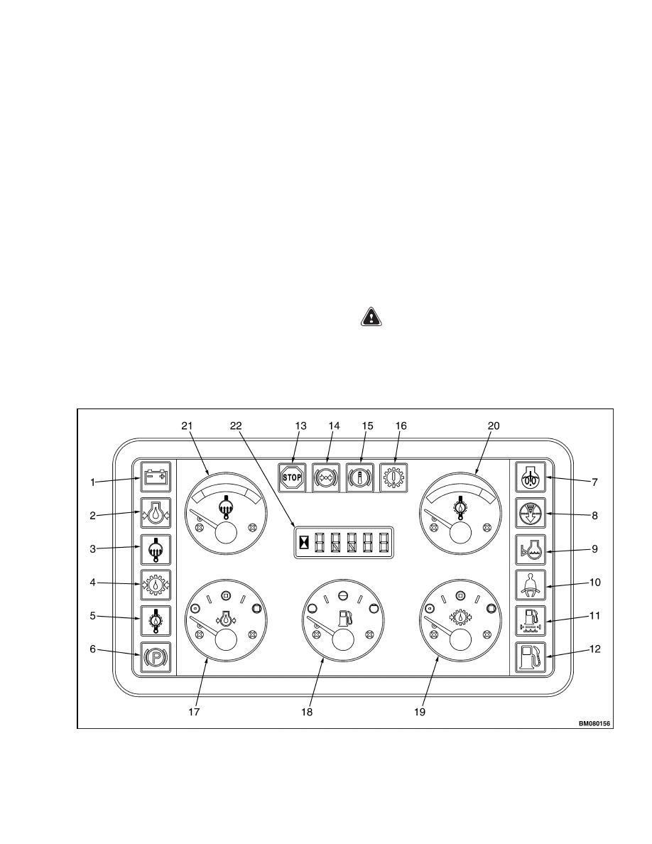
WARNING
If any of the instruments do not operate as de-
scribed in the following tables, DO NOT oper-
ate lift truck until problem is corrected.
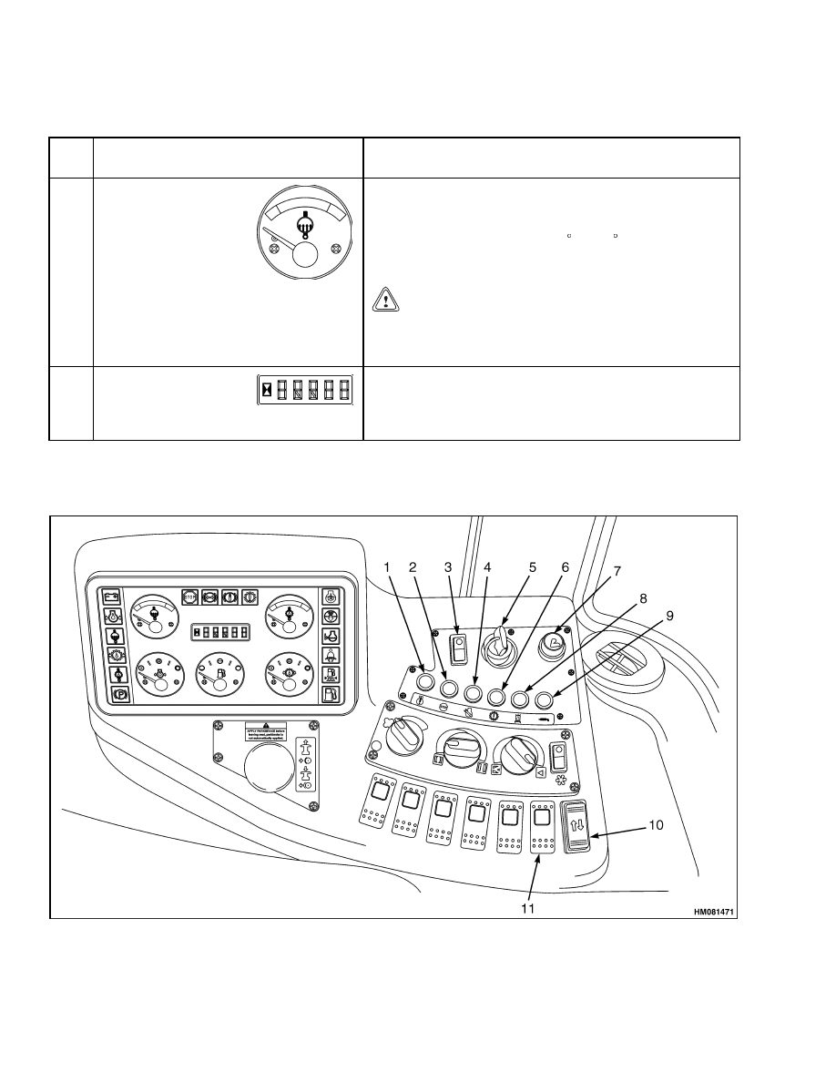
Figure 1. Instrument Panel and Indicators
1
Description
2200 SRM 1110
Table 1. Instrument Panel and Indicators
Item
No.
Item
Function
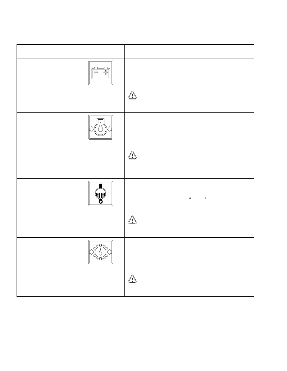
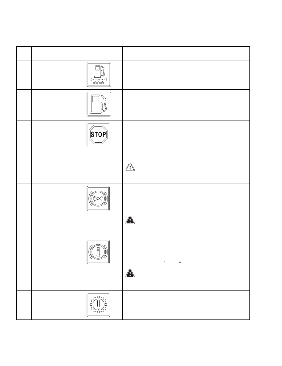
1
Battery Charging
Condition Warning
Light
The red light will come ON when the key switch is in
the ON position and the engine is not running. The light
must be OFF while the engine is running. If the light
comes ON during operation, there is a problem that must
be checked immediately.
CAUTION
Do not continue to operate the lift truck if the red
light is ON at engine speeds above idle.
2
Low Engine Oil
Pressure Warning
Light
The red light is ON when the key switch is in the ON
position. The light must be OFF when the engine is
running. If the engine oil pressure is less than or equal to
69 kPa (10 psi), the red light will come ON and a buzzer
will sound. The central warning light and the engine stop
warning light will also come ON.
CAUTION
Stop the engine immediately if the red light is ON
while the engine is running or lift truck damage
may occur.
3
Coolant Temperature
Warning Light
The red light is ON for 3 seconds when the key switch is
in the ON position. The light must be OFF when the
engine is running. If the engine coolant temperature is
equal to, or greater than 120 C (248 F), the red light and
central warning light will come ON and a buzzer will
sound.
CAUTION
Do not continue to operate the lift truck when the
light is ON or lift truck damage may occur.
4
Transmission Oil
Pressure Warning
Light
The red light is ON for 3 seconds when the key switch is
in the ON position. The light must be OFF when the
engine is running. If the transmission oil pressure is
less than or equal to 1000 kPa (145 psi), the red light
and central warning light will come ON and a buzzer
will sound.
CAUTION
Do not continue to operate the lift truck if the red
light is ON or lift truck damage may occur.
2
2200 SRM 1110
Description
Table 1. Instrument Panel and Indicators (Continued)
Item
No.
Item
Function
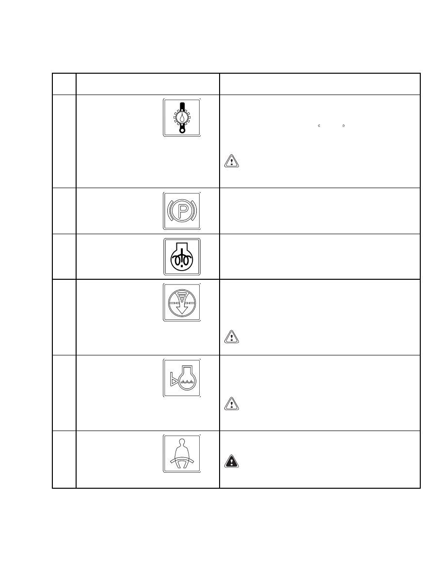
5
Transmission Oil
Temperature Warning
Light
The red light is ON for 3 seconds when the key switch is
in the ON position. The light must be OFF when the
engine is running. If the transmission oil temperature is
equal to or greater than 132 C (270 F), the red light will
come ON and a buzzer will sound. The central warning
light will also come ON and the stop light flashes.
CAUTION
Do not continue to operate the lift truck if the red
light is ON or lift truck damage may occur.
6
Park Brake Warning
Light
This light is ON when the parking brake is applied.
7
Not Used
8
Engine Air Filter
Warning Light
The red light is ON when the key switch is in the ON
position and must go OFF when the engine is running.
The engine air filter warning light is ON when the engine
air filter is dirty or has an obstruction. If the light is ON,
replace the filter element.
CAUTION
Lift truck performance can be effected.
9
Coolant Level
Warning Light
The red light will be ON when the key switch is in the
ON position. The light must go OFF when the engine is
running. If the engine coolant is low, the red light and
central warning light will come ON.
CAUTION
Do not continue to operate the lift truck when the
light is ON or lift truck damage may occur.
10
Seat Belt Warning
Light
This orange light is ON for 10 seconds after the key
switch is placed in the ON position.
WARNING
Before driving the lift truck, always fasten your
safety belt or personnel injury may occur.
3
Description
2200 SRM 1110
Table 1. Instrument Panel and Indicators (Continued)
Item
No.
Item
Function
11
Not Used
12
Fuel Reserve Warning
Light
The orange light will be ON for 3 seconds when the key
switch is in the ON position. The light must go OFF
when the engine is running. The orange fuel reserve
warning light and central warning light are ON when the
fuel level is below 10% of the fuel tank capacity.
13
Engine STOP Warning
Light
The red light will come ON for 3 seconds when the key
switch is in the ON position. The light must go OFF
when the engine is running. When either the engine
coolant temperature, transmission oil temperature, or the
engine oil pressure reach the alarm values, the stop light
and central warning light will come ON and a buzzer
will sound.
CAUTION
When the light is ON, immediately STOP the lift
truck or lift truck damage may occur.
14
Low Brake Pressure
Warning Light
The red light will be ON for 3 seconds when the key
switch is in the ON position. The light must be OFF
when the engine is running. The red light and central
warning light are ON when the pressure in the brake
system is low.
WARNING
Do not operate the lift truck when the light is ON or
personnel injury may occur.
15
High Brake
Temperature Warning
Light
The red light is ON for 3 seconds when the key switch is
in the ON position. The light must be OFF when the
engine is running. This red light and central warning
light are ON when the temperature in the brake system
is higher than 110 C (230 F) for the brake system.
WARNING
Do not operate the lift truck when the light is ON or
personnel injury may occur.
16
Not Used
4
2200 SRM 1110
Description
Table 1. Instrument Panel and Indicators (Continued)
Item
No.
Item
Function
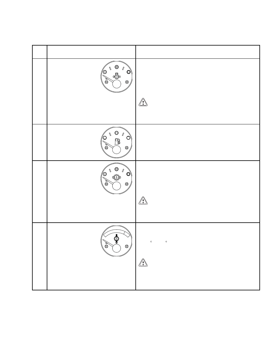
17
Engine Oil Pressure
Gauge
This gauge indicates normal engine oil pressure when
the needle is approximately in the middle of the scale.
If the engine oil pressure drops to less than or equal to
69 kPa (10 psi), the red light will come ON and a buzzer
will sound. The central warning light and the engine stop
warning light will also come ON.
CAUTION
Stop the engine immediately if the red light is ON
while the engine is running or lift truck damage
may occur.
18
Fuel Level Gauge
This gauge indicates the level of fuel in the fuel tank.
When the fuel level is 10% or less of the tank capacity, the
red warning and central warning light will come ON.
19
Transmission Oil
Pressure Gauge
This gauge indicates the transmission oil pressure while
the engine is running. During normal operation, the
gauge needle is approximately in the middle of the scale.
If the pressure drops to 1000 kPa (145 psi) or less, the
red warning light and central warning light will come
ON and a buzzer will sound.
CAUTION
Do not continue to operate the lift truck when the
gauge indicates that the transmission oil pressure
is low or lift truck damage may occur.
20
Transmission Oil
Temperature Gauge
This gauge indicates the transmission oil temperature
while the engine is running. During normal operation the
gauge needle will be in the green zone. If the temperature
is 132 C (270 F) or greater, the red warning light and
central warning light will come ON and a buzzer will
sound.
CAUTION
Do not continue to operate the lift truck when the
gauge indicates that the transmission oil tempera-
ture is high (needle in the red zone) or lift truck
damage may occur.
5
Description
2200 SRM 1110
Table 1. Instrument Panel and Indicators (Continued)
Item
No.
Item
Function
21
Coolant Temperature
Gauge
This gauge indicates engine coolant temperature when
the key switch is ON or the engine is running. During
normal operation the gauge needle will be in the green
zone. If the temperature is 120 C (248 F) or greater, the
red warning light and central warning light will come
ON and a buzzer will sound.
CAUTION
Do not continue to operate the lift truck when the
gauge indicates that the engine is hot (needle in the
red zone) or lift truck damage may occur.
22
Hourmeter and Error
Code Indicator
The hourmeter operates while the engine is running.
Periodic Maintenance recommendations are based on
these hours. A second hourmeter can/may be located on
the left-hand side of the lift truck next to the fuel fill cap.
ERROR CODE DISPLAY
Figure 2. Switches
6
2200 SRM 1110
Description
Table 2. Switches Description
Item
No.
Item
Description
1
Limited Operating Conditions
Warning Light
The orange warning light will come ON when the engine
operating conditions are near the maximum permissible
values. Engine power de-rating may take place.
NOTE: This light is also used when the diagnostic mode is se-
lected.
CAUTION
Operating conditions might deteriorate. Monitor en-
gine operating conditions or lift truck damage may oc-
cur.
2
Engine Stop
This red engine stop warning light comes ON when the
engine operating conditions exceed maximum permissible
values. Immediately shutoff engine.
NOTE: This light is also used when the diagnostic mode is se-
lected.
3
Optional Stair Lights ON/OFF
Switch
There are two stair lights ON/OFF switches. This optional
switch is located next to the engine stop light and the other
switch is located at the base of the stairs. Use one of these
switches to either switch ON or OFF stair lights.
4
Engine Maintenance Light
This orange light is ON when maintenance is required.
5
Key Switch
The key switch has three positions:
No. 1 Position: OFF position. De-energizes all electric
circuits except for the horn and headlights. See Figure 2.
No. 2 Position: ON position. Energizes all electric circuits
except the starter circuit. The key switch will be in this
position during normal operation.
No. 3 Position: START position. Energizes the starter motor
for starting the engine. A spring returns the key to position
No. 2 (ON position) when the key is released.
NOTE: There is a mechanical lockout that prevents the key
switch from being returned to the START position without
first being returned to the OFF position.
6
Transmission Warning Light
This red warning light will come ON in the event of a
transmission fault.
7

Description
2200 SRM 1110
Table 2. Switches Description (Continued)
Item
No.
Item
Description
7
Optional Auxiliary 12 VDC Power
Outlet
12VDC Max 10 Amps outlet.
8
Optional Hydraulic Filter Warning
Light
Orange warning light will come ON when hydraulic filter
needs cleaning or replaced.
9
Optional Auto Lubrication Warning
Light
Orange light comes ON when grease level in auto lubrication
reservoir is low.
10
Diagnostic Switch ON/OFF
In case of an active fault, indicated by the stop/warning
lights, turn the key switch OFF, then press and hold
diagnostic switch in ON position. Turn the key switch to the
ON position.
If no active faults are recorded, the engine stop and limited
operating conditions warning lights will come ONand stay
ON. If active faults are recorded, the limited operating
conditions warning light will flash once to indicate the start
of the fault code sequence. The engine stop will then flash out
a three digit diagnostic code (e.g. flash, flash pause indicates
the number 2). When the number has been displayed, the
engine stop light will come ON again. Each flash code is
displayed three times before advancing to the next code. This
process repeats until the diagnostic switch is released or the
diagnostic switch increment/decrement is operated.
11
Increment/Decrement Diagnostic
Switch
In case of more than one active fault, the increment/decrement
switch can be used to display each active fault code.
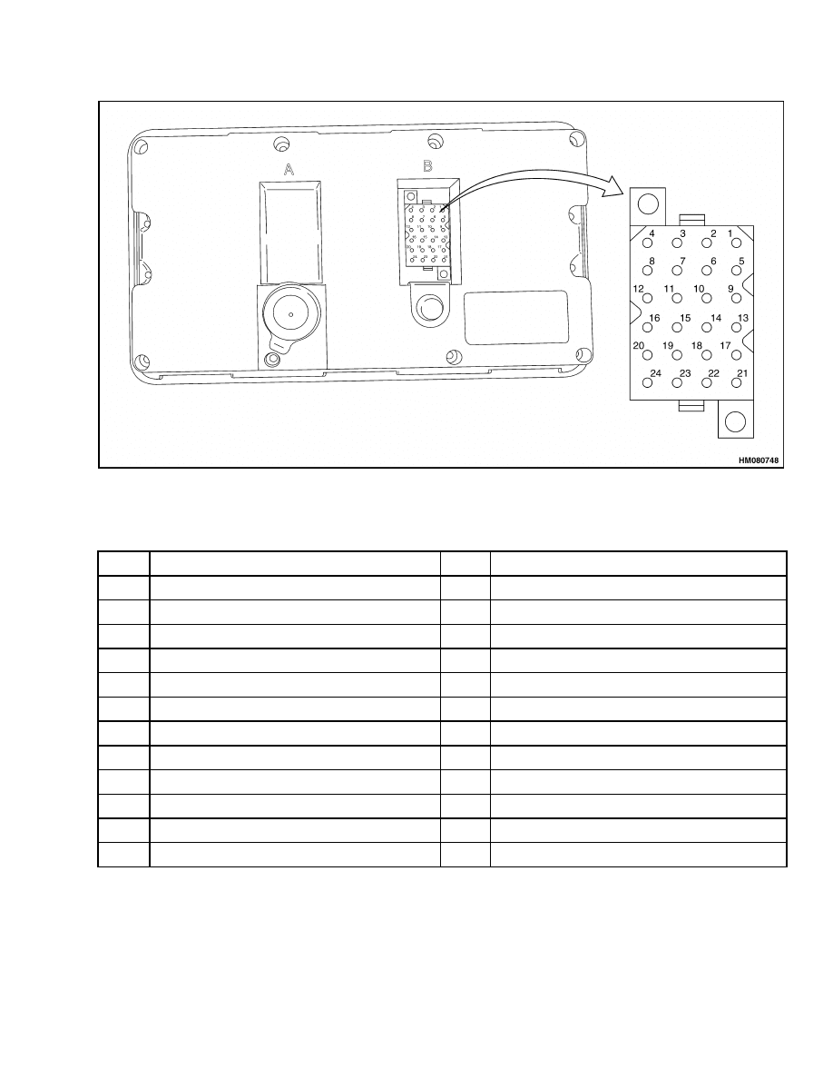
CONNECTOR
The instrument panel is connected to the system by
means of one connector. The connector is located at
rear of instrument panel. See Figure 3 and Table 3.
Seat Switch Logic
This function warns the operator when leaving the
seat without applying park brake. 2.5 seconds after
having detected this condition, the buzzer is acti-
vated and stays ON for 10 seconds.
The seat switch is connected to pin number 2. When
seat is occupied, pin number 2 is connected to ground.
When seat is not occupied, input to pin number 2 is
open.
8
2200 SRM 1110
Description
Figure 3. Connector
Table 3. Pin Description
Pin
Description
Pin
Description
1
Battery positive input
13
Brake system pressure light input
2
Seat switch input
14
RS-232 Receive input
3
Battery charging light input
15
RS-232 Transmission output
4
Ground
16
RS-232 Ground
5
Engine coolant level light input
17
Buzzer output
6
Brake system temperature light input
18
Shutdown output
7
Park brake monitor input
19
Central light output
8
Start aid/Engine warning light input
20
Engine coolant temperature gauge input
9
Engine combustion air filter light input
21
Engine oil pressure gauge input
10
Fuel filter light input
22
Transmission oil pressure gauge input
11
Neutral gear input
23
Transmission oil temperature gauge input
12
Stop engine light input
24
Fuel level gauge input
9
Description
2200 SRM 1110
Central Warning Light Output
This output is at pin number 19 and switches to
ground when any of the following conditions occur:
• Engine oil pressure is low
• Engine coolant temperature is high
• Transmission oil pressure is below 999 kPa
(145 psi)
• Transmission oil temperature is above 132 C
(269 F)
• Fuel level is below 10% of the capacity
• Brake system pressure warning light is ON
• Brake system temperature warning light is ON
• Engine coolant level warning light is ON
• Intake manifold air temperature is high
• Engine stop light is ON
Buzzer Output
This output is at pin number 17 and switches to
ground when any of the following conditions occur:
• Engine oil pressure is low
• Engine coolant temperature is high
• Transmission oil pressure is below 999 kPa
(145 psi)
• Transmission oil temperature is above 132 C
(269 F)
• When the operator is not present and park brake is
not applied. The buzzer will be ON for 10 seconds.
• Intake manifold air temperature is high
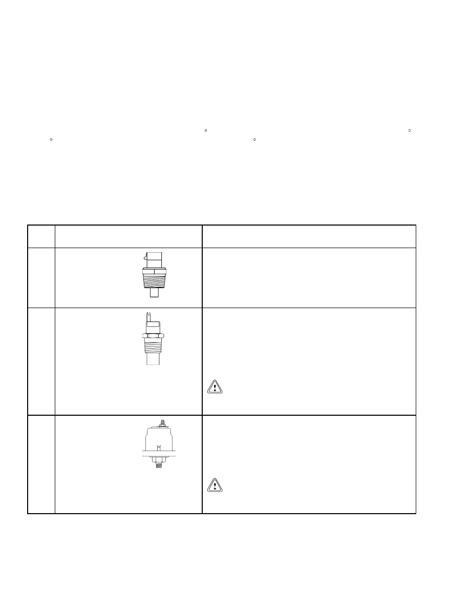
Table 4 describes senders which send electronice sig-
nals to the display panel.
Table 4. Sender Description
Item
No.
Item
Function
1
Water Temperature
Sender
The water temperature sender is mounted in the engine
block and senses the water temperature. If the water
temperature exceeds the specified temperature, the
sender sends a signal to the control panel and lights the
coolant temperature indicator. This signal also drives the
coolant temperature gauge.
2
Transmission Oil
Temperature Sender
The transmission oil temperature sender unit is mounted
in the transmission oil sump and senses the transmission
fluid temperature. When the transmission temperature
exceeds system specifications, the sender sends a signal
to the instrument panel and lights the transmission oil
temperature warning light. This signal also drives the
transmission oil temperature gauge.
CAUTION
Do not continue to operate the lift truck when the
gauge indication is in the red area of the gauge.
3
Engine Oil Pressure
Sender
The engine oil pressure sender is located on the side of the
engine block and senses the engine oil pressure. If the oil
pressure drops lower than specifications, the sender sends
a signal to the control panel and lights the engine oil
pressure indicator. The engine oil pressure sender signal
also drives the engine oil pressure gauge.
CAUTION
Do not continue to operate the lift truck if the red
light is ON at engine speeds above idle.
10
2200 SRM 1110
Description
Table 4. Sender Description (Continued)
Item
No.
Item
Function
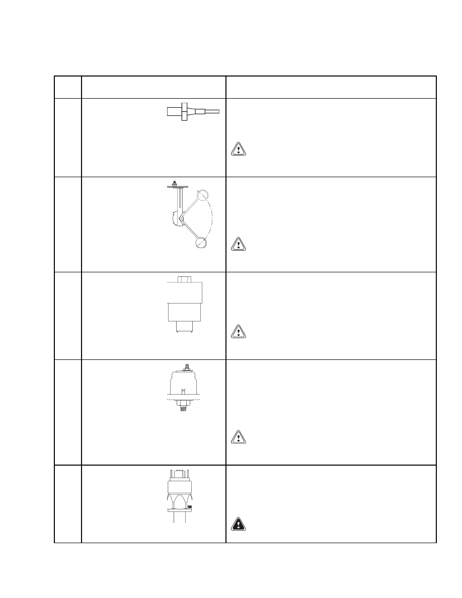
4
Low Coolant Sender
The low coolant sender is mounted in the coolant system
radiator near the top of the tank. It senses the fluid level
and, when low, sends a signal to the control panel and
lights the coolant system fluid low warning indicator.
CAUTION
Do not continue to operate the lift truck if the orange
light is ON during operation.
5
Fuel Level Sender
The fuel level sender is installed in the fuel tank and
indicates when the fuel is low. An internal float sends a
signal to the control panel and lights the fuel level low
warning indicator. A signal is also sent to the fuel level
gauge to indicate the amount of fuel remaining in the
tank.
CAUTION
Do not continue to operate the lift truck if the orange
light is ON during operation.
6
Vacuum Switch
The vacuum switch is mounted on the air filter housing
(left side of the truck). It senses the air intake pressure
and sends a signal to the instrument panel. It switches
warning light 8 ON when the air intake pressure drops
below 6.4 kPa (0.9 psi).
CAUTION
Lift truck performance will be limited when the red
light is ON.
7
Transmission Oil
Pressure Sender
The transmission oil pressure sender unit is mounted
in the transmission on the engine side and senses the
transmission fluid pressure. When the transmission oil
pressure drops below specifications, the sender sends a
signal to the instrument panel and lights the transmission
oil pressure warning light 4. The transmission oil pressure
sender also drives the transmission oil pressure gauge.
CAUTION
Do not continue to operate the lift truck when the
red light is ON at engine speeds above idle.
8
Low Pressure Sender
The low pressure sender is mounted in the manifold on
the cab tilt frame and senses the brake system pressure.
When pressure drops below specified value, the sender
sends a signal to the instrument panel and lights the low
pressure warning light 14.
WARNING
Never operate a truck with a brake malfunction.
11
Instrument Panel Component Replacement
2200 SRM 1110
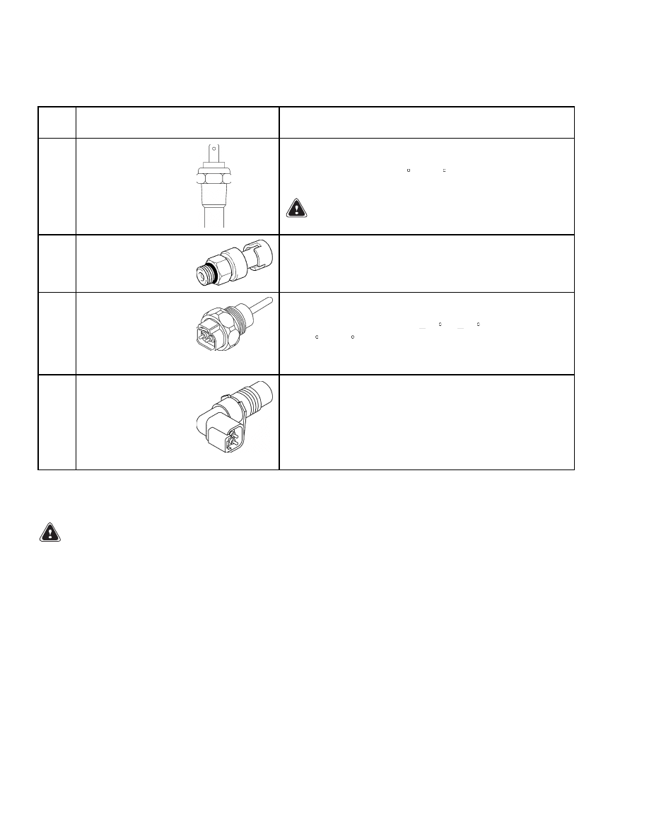
Table 4. Sender Description (Continued)
Item
No.
Item
Function
9
Brake Temperature
Sender
The brake temperature senders are mounted in the wheel
hubs and sense the brake fluid temperature. If the fluid
temperature exceeds 110 C (230 F), the senders send a
signal to the instrument panel and lights warning light 15.
WARNING
Never operate a truck with a brake malfunction.
10
Intake Manifold
Pressure Sensor
This is an active sensor with and output between 0 and 5
volts. The ECM will recognize the output to be valid if it
is between 0.5 volts representing 52 kPa (8 psi) and 4.5
volts representing 306 kPa (44 psi).
11
Intake Manifold
Temperature Sensor
This is a thermistor-type sensor with an output between 0
and 5 volts. The ECM will recognize the output to be valid
if it is between 0.2 volts at
40 C ( 40 F) and 4.9 volts
at 150 C (302 F). Sensor diagnostics will detect a fault if
the input voltage is outside this range for more than 2
seconds continuously.
12
Crankshaft Position
Sensor
This is a magnetic-type sensor that measures both
crankshaft speed and position. The sensor will measure
speeds above 246 rpm when the output will be greater
than 0.4 volts peak to peak. The sensor detects the
passing of teeth on a wheel. These teeth are spaced at 1/36
intervals of the wheel. One tooth is missing to facilitate
the position measurement. There are a total of 36 teeth.
Instrument Panel Component Replacement
WARNING
Before replacing any components, fully lower
all parts of the mast and tilt it forward until the
tips of the forks touch the ground. This action
will prevent the mast from lowering suddenly
if the control lever is accidently moved.
ALWAYS disconnect the battery and remove op-
erator key before replacing components.
Never have any metal on your fingers, arms, or
neck. These metal items can accidentally make
an electrical connection and may cause an in-
jury.
Meters, display panels, most indicators, and senders
are not repairable items. The most accurate and usu-
ally easiest check for proper operation of individual
meters, indicators, or senders is direct replacement.
The most common cause of failure is poor connections
or damaged or improper wiring, and not the meter
indicator or sender. This section only has the re-
placement procedures. Before a meter, display panel,
indicator, or sender is replaced, make the following
checks.
1.
Check that other meters and electrical circuits
operate correctly.
2.
Check that the battery is fully charged and has a
good ground, and cable terminals are clean and
tight.
3.
Check that the wiring and connections to meter,
indicator, or sender are tight and in good condi-
tion.
12
2200 SRM 1110
Instrument Panel Component Replacement
INSTRUMENT PANEL
Remove
NOTE: The only replaceable parts of the instrument
panel are the lights.
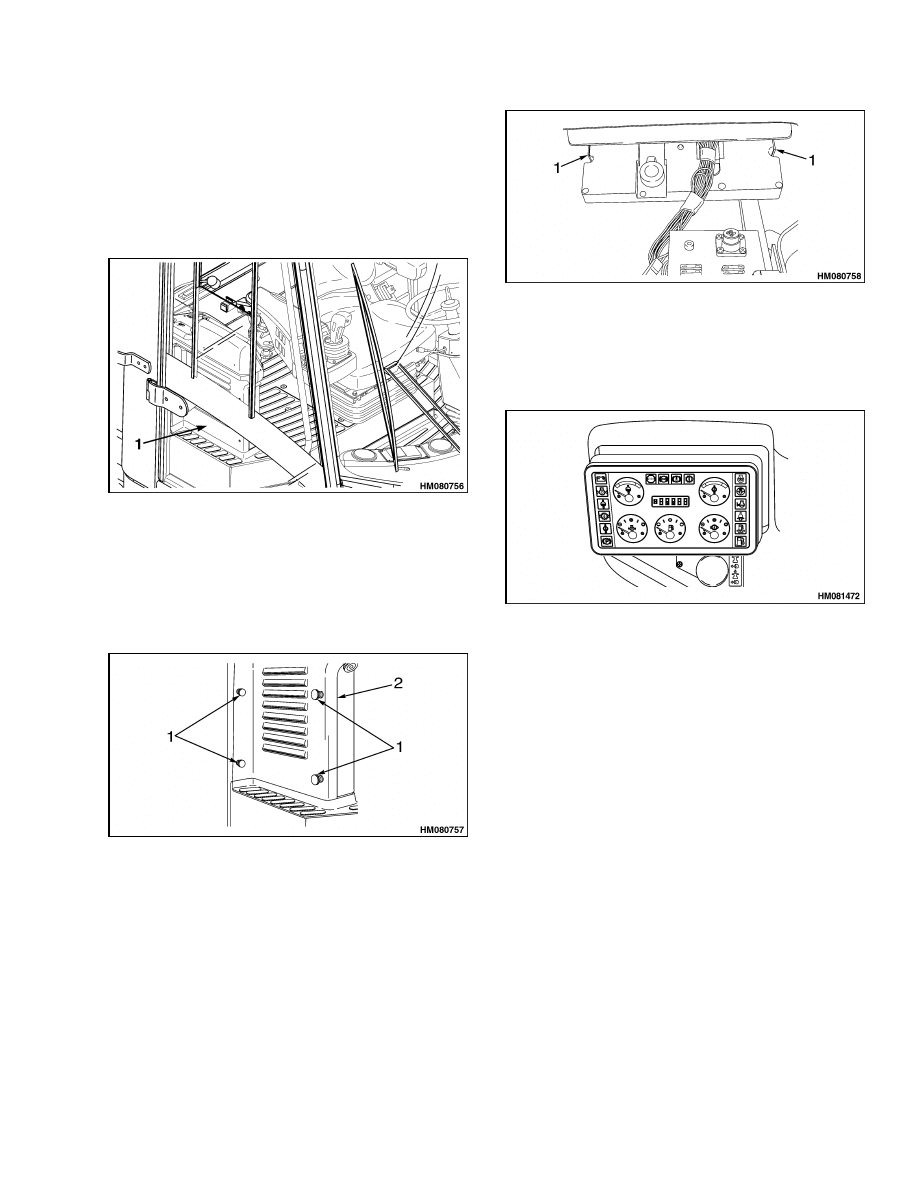
1.
Locate the fuse panel. See Figure 4.
1.
FUSE PANEL
Figure 4. Fuse Panel Location
2.
Disconnect ground lead of battery.
3.
Loosen four retaining screws and remove the fuse
panel cover. See Figure 5.
1.
RETAINING SCREWS
2.
FUSE PANEL COVER
Figure 5. Fuse Panel Screws
4.
From the fuse panel side, using a flat blade
screwdriver, depress clips holding instrument
panel in place. Left side first, then right side.
See Figure 6.
1.
PANEL CLIPS
Figure 6. Fuse Panel Clips
5.
Pull instrument panel away from the console.
See Figure 7.
Figure 7. Instrument Panel Removal
6.
Disconnect plug from socket.
7.
Loosen 12 screws at rear of instrument panel.
8.
Remove rear cover from instrument panel.
LIGHT
Replace
1.
Turn light holder counterclockwise and remove.
2.
Insert replacement light holder.
3.
Turn replacement light holder clockwise and
tighten.
4.
Mount cover.
13
Sender Replacement
2200 SRM 1110
Sender Replacement
FUEL LEVEL SENDER
WARNING
Before replacing any components, fully lower
all parts of the mast and tilt it forward until the
tips of the forks touch the ground. This action
will prevent the mast from lowering suddenly
if the control lever is accidently moved.
ALWAYS disconnect the battery and remove op-
erator key before replacing components.
Never have any metal on your fingers, arms, or
neck. These metal items can accidentally make
an electrical connection and may cause an in-
jury.
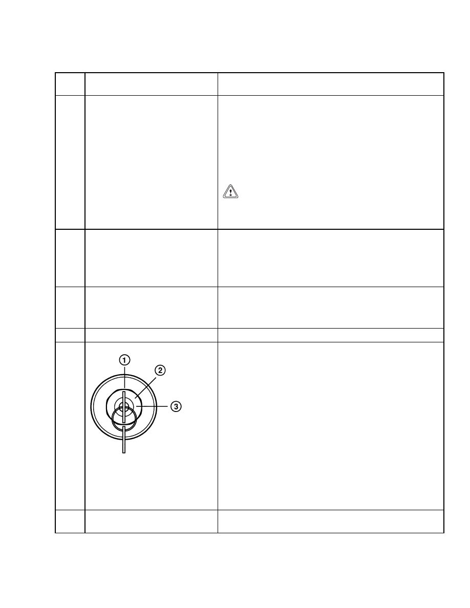
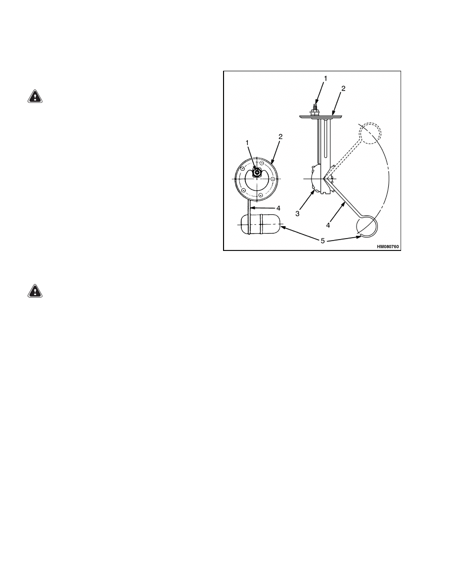
The fuel level sending unit is mounted to fuel tank
surface (usually top surface) with screws through
the sender plate and gasket. See Figure 8. Correct
sender operation and screw hole alignment can only
be obtained with plate mounted in one position.
Replace sender as follows:
WARNING
All fuel vapors are extremely explosive. Do not
have sparks or flames around vehicles or fuel
storage and service areas. Make sure there is
no source of open flame or sparks in the vicin-
ity. Use caution to prevent sparks from tools.
1.
Turn key switch to OFF position. Disconnect
battery positive cable at battery. Install a lock
or tag on connector to prevent connection.
2.
Disconnect sender wire at sender.
3.
Remove screws that fasten sender plate to tank.
4.
Remove sender.
5.
Carefully install new sender. Use a new gasket.
6.
Verify screw holes are aligned and install screws.
Tighten screws enough to partially compress gas-
ket to prevent leaks.
7.
Remove tape from wire connector and install con-
nector on sender terminal.
1.
ELECTRICAL
TERMINAL
2.
PLATE
3.
SENDER UNIT
4.
FLOAT ARM
5.
FLOAT
Figure 8. Fuel Level Sender
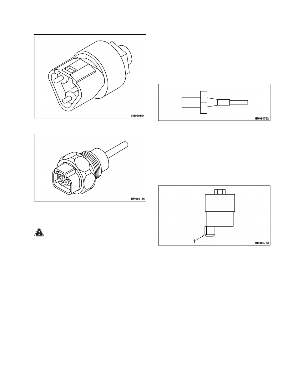
PRESSURE SENDER
NOTE: If applicable, replace O-ring when replacing
sender.
1.
Turn key switch to OFF position.
2.
Disconnect electrical connector.
3.
Remove pressure sender. See Figure 9.
4.
Install new pressure sender.
TEMPERATURE SENDER
NOTE: If applicable, replace O-ring when replacing
sender.
1.
Turn key switch to OFF position.
2.
Disconnect electrical connector.
3.
Remove temperature sender. See Figure 10.
4.
Install new temperature sender.
14
2200 SRM 1110
Sender Replacement
Figure 9. Pressure Sender
Figure 10. Temperature Sender
LOW COOLANT SENDER
WARNING
High temperature risk. Radiator temperature
may be high and radiator may be pressurized.
NOTE: Verify system fluid is drained so the level is
below sender to prevent leakage when sender is re-
moved.
1.
Turn key switch to OFF position.
2.
Disconnect sender wire. See Figure 11.
3.
Turn sender counterclockwise and remove.
4.
Install a new sender.
Use Teflon tape.
Turn
clockwise and tighten. Torque 5.6 ±0.6 N•m (50
±5 lbf in).
5.
Connect sender wire.
Figure 11. Low Coolant Sender
VACUUM SWITCH
1.
Turn key switch to OFF position.
2.
Disconnect amp connector. See Figure 12.
3.
Remove vacuum switch.
4.
Install a new vacuum switch.
1.
AMP CONNECTOR
Figure 12. Vacuum Switch
15
Sender Replacement
2200 SRM 1110
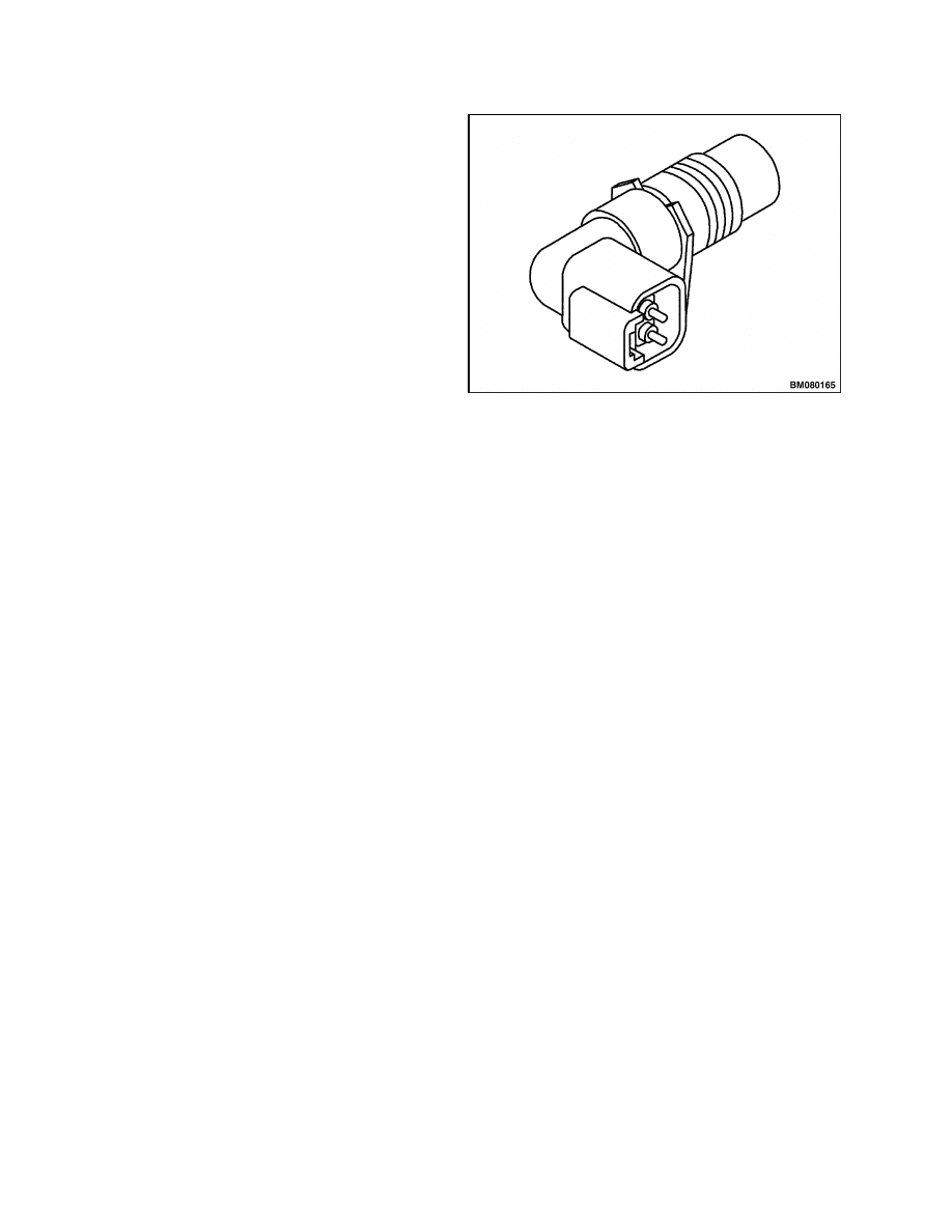
CRANKSHAFT POSITION SENSOR
NOTE: If applicable, replace O-ring when replacing
sensor.
1.
Turn key switch to OFF position.
2.
Disconnect electrical connector.
3.
Remove crankshaft position sensor.
See Fig-
ure 13.
4.
Install new crankshaft position sensor.
Figure 13. Crankshaft Position Sensor
16


TECHNICAL PUBLICATIONS
2200 SRM 1110
8/04 (7/04) Printed in United Kingdom
Document Outline
- toc
- tables
Wyszukiwarka
Podobne podstrony:
910110 2200SRM0143 (08 2004) UK EN
1578950 2200SRM1119 (08 2004) UK EN
1565181 2000SRM1108 (08 2004) UK EN
1538373 2200SRM1065 (02 2004) UK EN
1559550 2200SRM1097 (10 2004) UK EN
910030 1400SRM0047 (08 2004) UK EN
1494143 2200SRM0939 (12 2004) UK EN
1519772 2200SRM1016 (10 2004) UK EN
897495 2200SRM0514 (01 2004) UK EN
1566270 0100SRM1118 (08 2004) UK EN
1564268 2200SRM1106 (01 2004) UK EN
897409 2200SRM0460 (08 1995) UK EN
1556871 2200SRM1105 (01 2004) UK EN
więcej podobnych podstron