ELECTRICAL SYSTEM
H40.00-52.00XM-16CH
(H1050, 1150HD-CH) [E117]
PART NO. 1578950
2200 SRM 1119

SAFETY PRECAUTIONS
MAINTENANCE AND REPAIR
• When lifting parts or assemblies, make sure all slings, chains, or cables are correctly
fastened, and that the load being lifted is balanced. Make sure the crane, cables, and
chains have the capacity to support the weight of the load.
• Do not lift heavy parts by hand, use a lifting mechanism.
• Wear safety glasses.
• DISCONNECT THE BATTERY CONNECTOR before doing any maintenance or repair
on electric lift trucks. Disconnect the battery ground cable on internal combustion lift
trucks.
• Always use correct blocks to prevent the unit from rolling or falling. See HOW TO PUT
THE LIFT TRUCK ON BLOCKS in the Operating Manual or the Periodic Mainte-
nance section.
• Keep the unit clean and the working area clean and orderly.
• Use the correct tools for the job.
• Keep the tools clean and in good condition.
• Always use HYSTER APPROVED parts when making repairs. Replacement parts
must meet or exceed the specifications of the original equipment manufacturer.
• Make sure all nuts, bolts, snap rings, and other fastening devices are removed before
using force to remove parts.
• Always fasten a DO NOT OPERATE tag to the controls of the unit when making repairs,
or if the unit needs repairs.
• Be sure to follow the WARNING and CAUTION notes in the instructions.
• Gasoline, Liquid Petroleum Gas (LPG), Compressed Natural Gas (CNG), and Diesel fuel
are flammable. Be sure to follow the necessary safety precautions when handling these
fuels and when working on these fuel systems.
• Batteries generate flammable gas when they are being charged. Keep fire and sparks
away from the area. Make sure the area is well ventilated.
NOTE: The following symbols and words indicate safety information in this
manual:
WARNING
Indicates a condition that can cause immediate death or injury!
CAUTION
Indicates a condition that can cause property damage!

Electrical System
Table of Contents
TABLE OF CONTENTS
General ...............................................................................................................................................................
Description .........................................................................................................................................................
Warning Devices ................................................................................................................................................
General ...........................................................................................................................................................
Description .....................................................................................................................................................
Operator-Controlled Horns .......................................................................................................................
Reverse Warning Horns/Lights ................................................................................................................
Warning Lights..........................................................................................................................................
Beacon Lights........................................................................................................................................
Brake Lights..........................................................................................................................................
Hazard Lights .......................................................................................................................................
Replace .......................................................................................................................................................
General ..................................................................................................................................................
Horns .....................................................................................................................................................
Horn Relay ............................................................................................................................................
Warning Lights/Bulbs ...........................................................................................................................
Light Assemblies...................................................................................................................................
Flashing Unit ........................................................................................................................................
Meters, Senders, System Warning Lights, and Switches ................................................................................
General ...........................................................................................................................................................
Alternator ...........................................................................................................................................................
General ...........................................................................................................................................................
Description .....................................................................................................................................................
Charging System Indicator and Accessory Power Supply ......................................................................
Remove ...........................................................................................................................................................
Install .............................................................................................................................................................
Troubleshooting..................................................................................................................................................
Diagrams, Schematics, or Arrangements .........................................................................................................
Figure 7. Main Wire Harness ...................................................................................................................
This section is for the following models:
H40.00-52.00XM-16CH (H1050, 1150HD-CH) [E117]
©2004 HYSTER COMPANY
i

"THE
QUALITY
KEEPERS"
HYSTER
APPROVED
PARTS
2200 SRM 1119
Description
General
This section has the description and repair procedures for electrical components. The instructions for replacing
parts of the warning devices is included. Also, the instructions for removal and installation of the alternator
is included in this section.
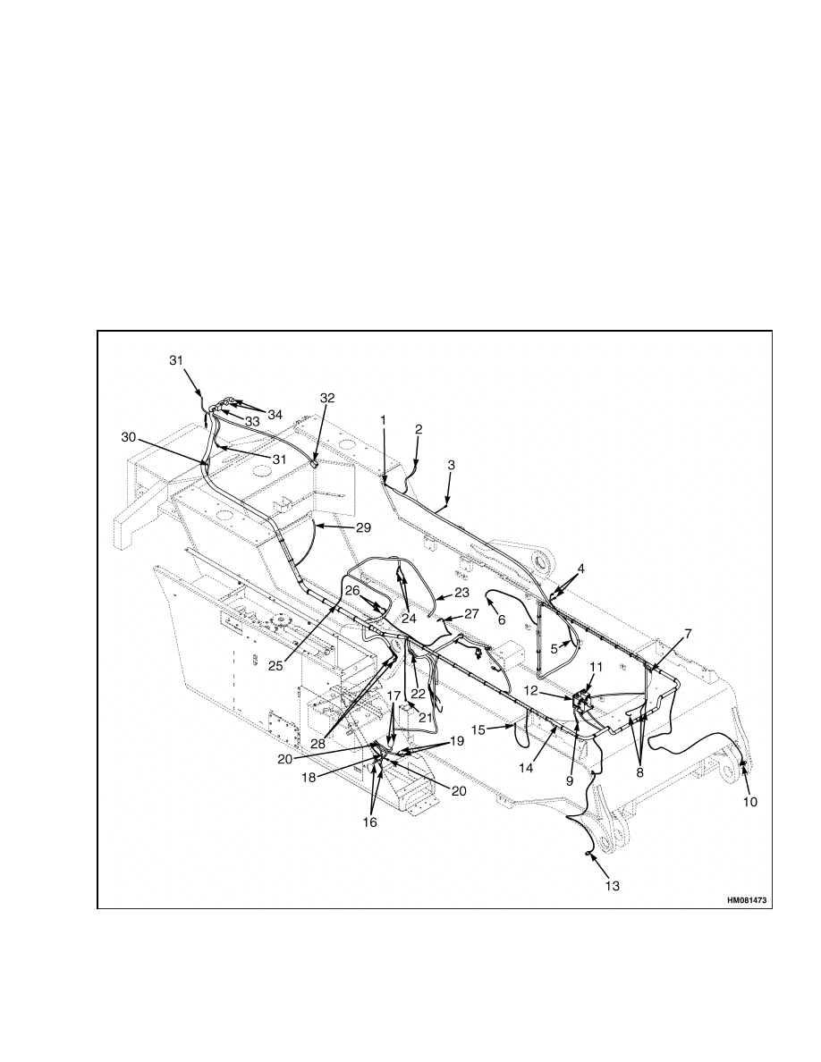
Description
The main part of the electrical system is the one piece
main electrical wire harness. The batteries provide
the main electrical wire harness with electricity and
then the main electrical wire harness transmits the
electricity to several components (senders, warning
lights, etc.). See Figure 1 and the section Instru-
ment Panel Indicators and Senders 2200 SRM
1110 for further information regarding senders and
indicator functions.
Figure 1. Main Electrical Wire Harness
1

Description
2200 SRM 1119
Legend for Figure 1
NOTE: SEE FIGURE 7 FOR DETAILED INFORMATION REGARDING CONNECTOR IDENTIFICATION.
Item No.
Connector
Description
1
C120 (black 2-way dt socket housing – DEUTSCH)
Light for night fuel filling
2
C95 (6.35 Faston terminal – LABINAL)
Hourmeter
3
C60 (6.35 Faston terminal – LABINAL)
Fuel Sender
C230 (black 3-way dt socket housing – DEUTSCH)
Stair Light Switch
4
C190 (black 4-way dt socket housing – DEUTSCH)
Lubrication
5
C235 (black 2-way dt socket housing – DEUTSCH)
Stair Light
6
C220 (black 2-way j timer socket housing A/B – AMP)
Air Filter
7
C20 (black 4-way dt socket housing – DEUTSCH)
Front Left-Hand Headlights
C40 (black 2-way j timer socket housing A/B – AMP)
Aux 1
C50 (green 2-way j timer socket housing A/B – AMP)
Aux 2
8
C30 (black 2-way dt socket housing – DEUTSCH)
Park Brake Solenoid
9
C150 (6.35 Faston terminal – LABINAL)
Hydraulic Restriction
10
C25 (90 , 6.35 Faston terminal – LABINAL)
Left-Hand Hub Temperature
11
C100 (female housing connector – ILME)
Mast 2
12
C90 (female housing connector – ILME)
Mast 1
13
C15 (90 , 6.35 Faston terminal – LABINAL)
Right-Hand Hub Temperature
14
C10 (black 4-way dt socket housing – DEUTSCH)
Front Right-Hand Headlights
15
C155 (Ø 5.3 mm (0.208 in.) ring terminal csa – G and H)
Brake Filter
16
C130 (Ø 10.5 mm (0.413 in.) ring terminal csa– G and H)
Disconnect Switch
17
C275 (Ø 8.4 mm (0.331 in.) ring terminal csa– G and H)
Alternator Fuse
18
C135 (black 4-way dt socket housing – DEUTSCH)
Fuse Box
19
C85 (Ø 5.3 mm (0.208 in.) and Ø 8.4 mm (0.331 in.) ring
terminal csa– G and H)
Starter Relay
C160 (black 2-way dtp pin housing – DEUTSCH)
Hydraulic Tank Heater
20
C240 (black 2-way dt socket housing – DEUTSCH)
Stair Light
21
C250 (Ø 10.6 mm (0.417 in.) ring terminal csa– LABINAL)
ECM (Engine Control Module)
Ground
22
C80 (black 12-way dt socket housing – DEUTSCH)
Transmission Harness
23
C170 (Ø 5.3 mm (0.208 in.) ring terminal csa – G and H)
Engine Oil Pressure
C270 (Ø 6.6 mm (0.260 in.) ring terminal csa– LABINAL)
Alternator +VE
C280 (Ø 5.3 mm (0.208 in.) ring terminal csa – G and H)
Alternator Signals
24
C290 (Ø 6.6 mm (0.260 in.) ring terminal csa– LABINAL)
Alternator Ground
25
C305 ( 4.0 mm (0.157 in.) socket terminal – SUMITOMO)
AC
2

2200 SRM 1119
Warning Devices
Item No.
Connector
Description
C400 (0-47 hd socket housing – DEUTSCH)
Engine Control
26
C390 (0-31 hd socket housing – DEUTSCH)
Engine Harness
27
C260 (56 series single housing – DELPHI)
Water Temperature Sender
C105 (Ø 13.5 mm (0.531 in.) ring terminal csa– G and H)
Ground
C110 (Ø 6.4 mm (0.252 in.) ring terminal csa – UTA)
Start
28
C115 (Ø 13.5 mm (0.531 in.) ring terminal csa– G and H)
+24V
29
C215 (Ø 5.3 mm (0.208 in.) ring terminal csa – G and H)
Radiator Coolant
30
C210 (black 6-way dt socket housing – DEUTSCH)
Rear Lights
C180 (black 4-way dt socket housing – DEUTSCH)
Wash Pumps
31
C395 (black 6-way dt socket housing – DEUTSCH)
AC Condenser
32
C410 (6-way housing – AMP)
Accelerator. Pedal
33
C144 (60 (0-12-48)-way drb socket housing key A -
DEUTSCH)
Cab Signals
C140 (0-16 hdp free socket clamped housing – DEUTSCH)
Cab Supplies
34
C405 (0-23 hdp free socket housing – DEUTSCH)
Cab CH
Warning Devices
GENERAL
Electrical warning devices used on the lift truck are
as follows:
• Operator-controlled horns
• Reverse warning horns/lights
• Warning lights
Operator-controlled horns permit the operator to
warn personnel that the equipment is near. System
warning lights and buzzers make an important sys-
tem condition known to the operator. They do this
by illuminating an indicator that is not normally
illuminated or by energizing a buzzer to sound.
Reverse warning horns automatically sound a warn-
ing that the equipment is moving in the reverse
direction. Warning lights automatically illuminate
to warn personnel that the equipment is operating
in a special way. Warning lights are also used to
warn personnel that the equipment is near. Some
of these warning devices need to be energized and
de-energized at a fast rate.
A separate flashing
device does this. Most equipment does not need each
of these warning devices.
DESCRIPTION
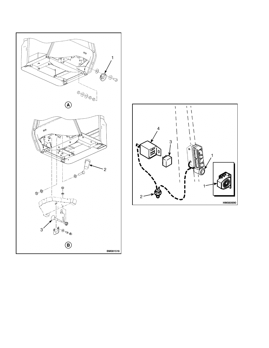
Operator-Controlled Horns
The operator controlled horn has a horn switch, a re-
lay, and horn. See Figure 2. The horn switch ener-
gizes the relay to close the power contacts and ener-
gize the horn. This makes the horn sound. The lower
sound level of equipment operation results in a horn
that is less loud and uses less current. This horn cur-
rent is directly controlled by the switch. The horn
switch is located at the operators position. The horn
is frequently installed near the front of the equip-
ment. The horn relay is installed in the side console.
3
Warning Devices
2200 SRM 1119
A. ELECTRICAL HORN
B. AIR HORN
1.
ELECTRICAL HORN
2.
COMPRESSOR, 24V
3.
AIR HORN
Figure 2. Operator-Controlled Horns
Reverse Warning Horns/Lights
The reverse warning horns are operated by a switch.
See Figure 3. They often use a flashing device to
make the sound of the horn begin and end repeat-
edly. This flashing device is part of the reverse warn-
ing horn. The switch is energized to the ON posi-
tion when the equipment is set to operate in the re-
verse direction. The switch will then energize the re-
lay to energize the horn. The switch is usually near
the transmission or shift linkage. The horn is most
frequently located under the back of the equipment.
The relay is located in the side console.
1.
HORN
2.
TRANSMISSION
SWITCH
3.
FLASHER
4.
BASE
Figure 3. Reverse Warning Horn Components
Warning Lights
The following types of warning lights are attached to
the lift truck:
• Beacon Lights
• Brake Lights
• Hazard Lights
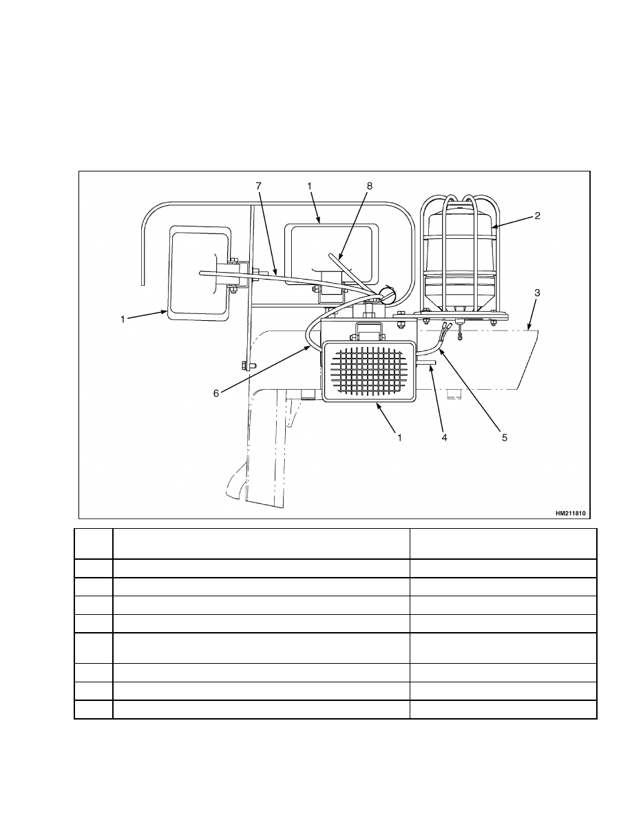
Beacon Lights
These warning lights indicate a particular type of
equipment operation. See Figure 4. They warn oth-
ers that the equipment is in the area or that the op-
erators view is limited by the particular operation.
These lights can be flashing lights or lights that look
as if they are flashing. A switch and a flashing device
4
2200 SRM 1119
Warning Devices
are used to operate the flashing light. The flashing
device is part of the light assembly. Lights that look
as if they are flashing have a disc that rotates around
the bulb. The disc directs the illumination away from
its surface. As the disc rotates, the directed illumina-
tion touches a fixed point once each revolution. This
makes the light look as if it flashes. Either type of
light can be connected to operate when the key switch
is in the ON position. They can also be connected to
operate with a particular operation of the equipment
such as: (1) equipment is set for reverse operation
or (2) operators platform is above 610 mm (24 in.).
When connected in this way, a separate switch is op-
erated automatically by the equipment function.
Item
No.
Connector
Description
1
N/A
Working Light (Halogen or HID)
2
N/A
Rotating Flashing Light
3
N/A
Cab
4
C10 (black 8 way dt socket housing – DEUTSCH)
Mate to connector on cab assembly.
5
C30 (4 mm socket terminal and 4 mm male bullet terminal
– SUMITOMO)
Beacon/Strobe
6
C20 (black 2 way dt socket housing – DEUTSCH)
Rear Drive Light
7
C50 (black 2 way dt socket housing – DEUTSCH)
Outer Front Flood Light
8
C40 (black 2 way dt socket housing – DEUTSCH)
Inner Front Flood Light
Figure 4. Light Assemblies
5

Warning Devices
2200 SRM 1119
Brake Lights
These warning lights indicate that the speed of the
lift truck will slow down. They warn others that the
lift truck will stop or decrease the speed severely.
These lights are positioned on the backside of the lift
truck and will be activated by operating the brake
pedal.
Hazard Lights
These warning lights will be used when the lift truck
has problems with driving or when the lift truck is
placed at a dangerous location.
Replace
General
Horns, light assemblies, flashing devices, buzzers,
and switches are not repairable items. The most ac-
curate and usually easiest checks for proper opera-
tion of individual items is direct replacement. How-
ever, the most common cause of failure are poor con-
nections or defective or improper wiring. Also, there
are no adjustments to perform. Therefore, only re-
placement procedures are given. Before replacing an
item, verify the following:
• Other electrical circuits are operating correctly.
• Battery is fully charged and the cable terminals are
clean and correctly connected.
• Wiring and connections to device are tight and in
good condition.
Horns
CAUTION
Audible alarms and horns have various levels
of output.
Be certain that any replacement
alarm or horn has an output that can be heard
in the area where the lift truck will be used.
1.
Verify the key switch is in the OFF position or
the battery is disconnected.
2.
Mark the horn wires for reconnection and discon-
nect them.
3.
Remove the screws, nuts, or other items fasten-
ing the horn to the equipment.
4.
Remove the horn and install the replacement.
5.
Tighten the screws, nuts, or other items fasten-
ing the horn to the equipment.
6.
Connect the wires, as marked, to the electrical
terminals.
Horn Relay
The horn relay, if used, is frequently located in the
side console in the cab. If necessary, follow the horn
electrical leads to find the relay. Replace the relay as
follows:
1.
Disconnect the battery or batteries to remove all
voltage from the terminals.
2.
Mark the wires for reconnection.
3.
Disconnect the wires.
4.
Remove the screws, nuts, or other items fasten-
ing the unit to the equipment.
5.
Remove the unit and install the replacement
unit.
6.
Tighten the screws, nuts, or other items fasten-
ing the unit to the equipment.
7.
Connect the marked wires to the correct termi-
nals or connectors.
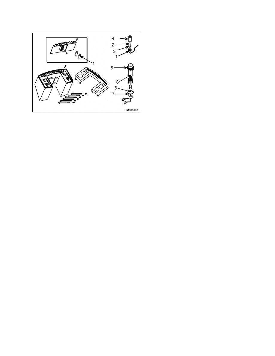
Warning Lights/Bulbs
1.
Access the different assemblies/bulbs as follows,
see Figure 4 and Figure 5:
a. Large instrument panel assemblies – push
the assembly base toward the lens and turn.
Do not let spring fall.
b. Small instrument panel assemblies – twist
the bulb assembly free of the lens tube.
c.
Exterior assemblies - remove the screws fas-
tening the lens.
2.
Push the bulb toward the base while turning the
bulb to the left.
3.
After the bulb is released, slowly remove it and
check position of pins on the base of the bulb.
6
2200 SRM 1119
Meters, Senders, System Warning Lights, and Switches
1.
BULB ASSEMBLY
2.
BULB PINS
3.
BULB
4.
LENS TUBE
5.
LENS
6.
LENS PIN
7.
BASE
8.
SLOT
Figure 5. Instrument Panel Lights Replacement
4.
Position new bulb so that the pin position is the
same.
5.
Align pins with slots in light assembly.
6.
Push the bulb toward the base. Turn to the right
until locked.
Light Assemblies
1.
Disconnect the battery or batteries to remove all
voltage from the terminals.
NOTE: Do Step 4 before Step 2 and Step 3 if there is
no access to assembly wire terminals.
2.
Mark the wires for reconnection.
3.
Disconnect the wires at the wire connectors or
light terminals.
4.
Remove the screws, nuts, or other items fasten-
ing the assembly to the equipment.
5.
Remove the assembly and put the new assembly
in the correct position.
NOTE: Some assemblies have no access to the wire
terminals after it is fastened to the equipment. If so,
do Step 7 before Step 6.
6.
Install the screws, nuts, or other items to fasten
the assembly to the equipment.
7.
Connect the marked wires to the correct termi-
nals or connectors.
Flashing Unit
Replace the flashing unit by holding the base and
pulling the unit until the pins are out of the base
clips. Align the replacement flashing unit pins. Push
the unit into position on the base.
Meters, Senders, System Warning Lights, and Switches
GENERAL
Meters, senders, and switches cannot be repaired.
The fan and wiper motors of the operator compart-
ment also cannot be repaired. These components are
replaced when they are defective. The most com-
mon cause of failure is a bad connection or defective
wiring. There are no adjustments. See the section
Instrument Panel Indicators and Senders 2200
SRM 1110 for replacement procedures. Before a me-
ter or sender is replaced, make the following checks:
1.
Make sure that the other meters and electrical
circuits are operating correctly.
2.
Make sure that the battery is charged, correctly
installed, and the cable terminals are clean and
tight.
3.
Make sure that the wires and connections to the
unit are tight and in good condition.
NOTE: See your dealer of Cummins engines for
starter repair.
7

Alternator
2200 SRM 1119
Alternator
GENERAL
CAUTION
Always move the battery disconnect switch
to the disconnected position before making
repairs. The diodes and resistors in the elec-
trical system can be damaged if the following
cautions are not followed:
• Do not disconnect the battery when the en-
gine is running. The voltage surge can dam-
age the diodes and resistors in the electrical
system.
• Do not disconnect an electric wire before the
engine is stopped and the switches are OFF.
• Do not cause a short circuit by connection
of the electric wires to the wrong terminals.
Verify correct identification is made of the
wire before it is connected.
• Verify the battery is the correct voltage and
polarity before it is connected.
• Do not check for current flow by making a
spark because the electronic components can
be damaged.
• These lift trucks have a 24-volt electrical sys-
tem (two 12-volt batteries in series). Use cau-
tion when working on the electrical system.
CAUTION
When using an arc welder, always disconnect
the ground lead from the lift truck battery to
prevent alternator or battery damage. Attach
the welding ground clamp as close to the weld
area as possible to prevent welding current
from damaging the bearings.
This section has the remove and install procedures
for the alternator with an internal regulator. Contact
your dealer for Cummins engines for starter repair.
The replacement procedures for meters and gauges is
in the section Instrument Panel Indicators and
Senders 2200 SRM 1110. The electrical schematic
diagram for the lift truck is shown in the section Di-
agrams 8000 SRM 1153.
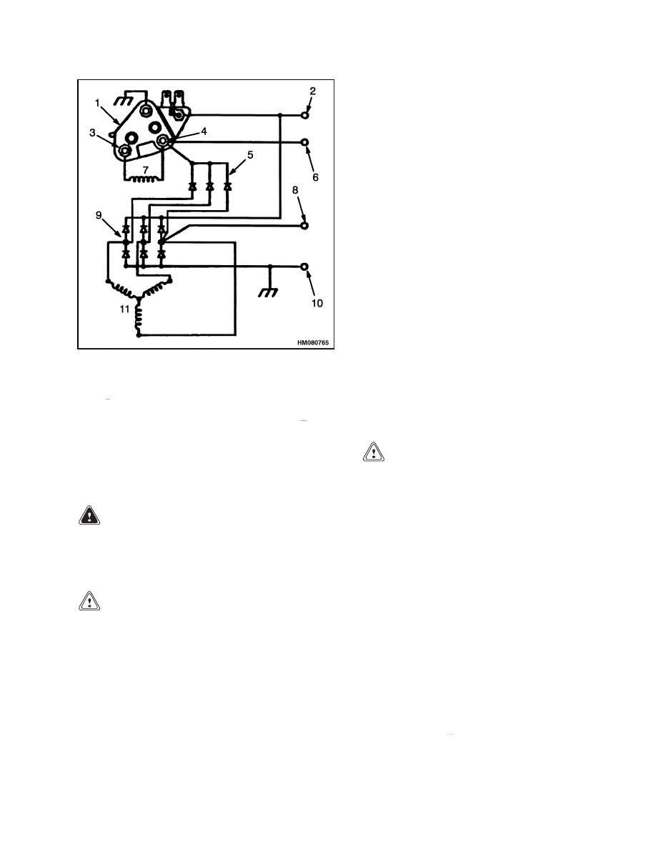
DESCRIPTION
The Delco Remy model 22-SI alternator generates
a 24-volt alternating current when the engine is
running. See Figure 6. The alternating current is
changed to a 70-ampere direct current by six silicon
diodes contained in a rectifier assembly (rectifier
bridge).
The diode set continues the process of
changing the alternating current to direct current
(DC). The rectifier bridge, diode set, and regulator
are all mounted in the end frame for the slip rings.
Output from the alternator is controlled by the regu-
lator. The regulator controls the alternator output
by controlling the voltage of the field. Voltage for
the regulator is supplied as part of the output volt-
age from the alternator.
The alternator has these main parts:
• Stator
• Rotor
• Two end frames
• Solid-state voltage regulator
The direct current, from the diodes, flows to the out-
put or battery (BAT, B+) terminal. The voltage is con-
trolled by the amount of current flowing through the
field winding in the alternator and the rpm of the ro-
tor. The voltage regulator inside the frame contains
a transistor, diodes, and capacitors. The voltage reg-
ulator must be replaced, if faulty.
The voltage regulator is installed in the end of the
alternator with the slip rings. The voltage regulator
controls the current at the output or BAT B+ termi-
nal. The voltage is set by controlling the current in
the field winding of the alternator. The voltage is set
by the manufacturer and is not adjustable. When the
key switch is turned to the IGN position, the voltage
regulator is energized.
Charging System Indicator and Accessory
Power Supply
The I terminal, which is connected to the ignition key
through an indicator light, supplies power to turn on
the regulator and supply field current. The I termi-
nal lines includes a bulb used as a charging indicator
light located on the instrument panel. As long as the
light is not ON, the alternator is functioning prop-
erly. If the indicator light comes ON while the engine
is running, the alternator is not charging properly,
which may be due to an alternator problem, wiring
problem, or other issue in the charging system. The
R or relay terminal is not used. The B or ground ter-
minal is connected to chassis ground.
8
2200 SRM 1119
Alternator
1.
REGULATOR
2.
BATTERY (B+)
TERMINAL
3.
F
4.
F+
5.
DIODE SET
6.
INDICATOR LIGHT
TERMINAL
7.
ROTOR FIELD
COIL
8.
RELAY TERMINAL
9.
BRIDGE DIODE
RECTIFIER (6)
10. GROUND (B )
TERMINAL
11. STATOR
Figure 6. Alternator Diagram
REMOVE
WARNING
Always move the battery disconnect lever to
the "disconnected" position before doing any
disassembly or repair to the parts of the elec-
trical system.
CAUTION
Before disassembling the alternator, make
marks on all housings to make sure of the
correct parts alignment during assembly.
1.
Disconnect the wires at the alternator. Use a
socket to move the arm of the belt tensioner and
remove the drive belt from the pulley. Remove
capscrews that fasten alternator to bracket.
2.
Remove the nut, pulley, and fan from the shaft.
Make alignment marks on the stator and frames.
Then remove the bolts that fasten the frames and
stator together.
3.
Remove the drive end frame and rotor from the
stator. If the bearing will be replaced, remove the
rotor from the drive end frame. Use a gear puller
or press and remove the bearing from the drive
end frame.
4.
Remove the nuts and screws that connect the sta-
tor leads, diode set, regulator, capacitor, termi-
nals, and rectifier assembly. Make a note of the
location, disassembly sequence, and the correct
connections of the nuts, insulators, screws, and
components for correct assembly.
INSTALL
1.
Install the nuts and screws that connect the sta-
tor leads, diode set, regulator, capacitor, termi-
nals, and rectifier assembly. Make sure to install
the parts in the brush end frame as noted during
disassembly. Make sure to align the alignment
marks on the stator to the brush end frame.
2.
Install the rotor in the stator and brush end
frame. Install the drive end frame on the rotor
and stator. Make sure to align the alignment
marks on the drive end frame and the stator. In-
stall the bolts that fasten the frames and stator
together.
CAUTION
Make sure the drive belt is correctly installed
and aligned on ALL pulleys before releasing
the belt tensioner. Belt damage will occur if not
correctly installed.
3.
Install the fan, pulley, washer, and nut on the ro-
tor shaft. Tighten the shaft nut to 95 to 108 N•m
(70 to 80 lbf ft). Install the alternator on the
bracket. Tighten the mount bolt to 81 to 95 N•m
(60 to 70 lbf ft). Use a socket to move the arm
of the belt tensioner and install the drive belt on
the pulley. Set the belt to the proper tension and
tighten the adjusting strap bolt.
4.
Install the electrical connectors on the correct
terminals. Tighten the terminal nuts and ground
screw to the following torque values:
Battery (B+) terminal - 9.0 to 13.6 N•m (80 to
120 lbf in)
Indicator (I) terminal - 1.7 to 2.8 N•m (15 to
25 lbf in)
Ground (B ) terminal - 5.6 to 6.8 N•m (50 to
60 lbf in)
9

Troubleshooting
2200 SRM 1119
Troubleshooting
PROBLEM
POSSIBLE CAUSE
PROCEDURE OR ACTION
Battery is charged above
normal.
Alternator is not charging correctly.
Repair or replace alternator.
Electrical ground in wire to brush or
clip.
Repair ground in wire to brush or
clip.
Battery uses more water
than normal.
Battery is charging more than nor-
mal.
Adjust or replace alternator or volt-
age regulator.
Leaks in the battery.
Replace battery.
Battery
will
not
hold
a
charge.
Loose wiring or broken connections.
Repair wiring or broken connections.
Alternator has a defect in the field
wiring, diodes, rectifier bridge, or
stator.
Repair or replace alternator.
Battery has a defect.
Replace battery.
There is no charge from the
alternator.
Worn or damaged brushes.
Replace worn or damaged brushes.
Weak springs for brushes.
Replace springs.
Brushes or holders do not move
freely.
Repair brushes or holders.
Dirt on the Brush End Frames.
Clean brush end frames.
There is no charge from the
alternator.
The indicator
light or ammeter indicates
a discharged condition when
the rpm is high and there
is a high current need (high
load).
There is an electrical ground in the
field winding.
Repair electrical ground.
Drive belt is not tight or is broken.
Adjust or replace drive belt.
10

2200 SRM 1119
Diagrams, Schematics, or Arrangements
PROBLEM
POSSIBLE CAUSE
PROCEDURE OR ACTION
Ammeter or the indicator
light indicates a discharged
condition at all speeds.
There is a short circuit in the diodes.
Repair or replace diodes.
There is an electrical ground at the
end of the windings.
Repair electrical ground.
Voltage regulator has a defect.
Replace voltage regulator.
11
Diagrams, Schematics, or Arrangements
2200 SRM 1119
12
2200 SRM 1119
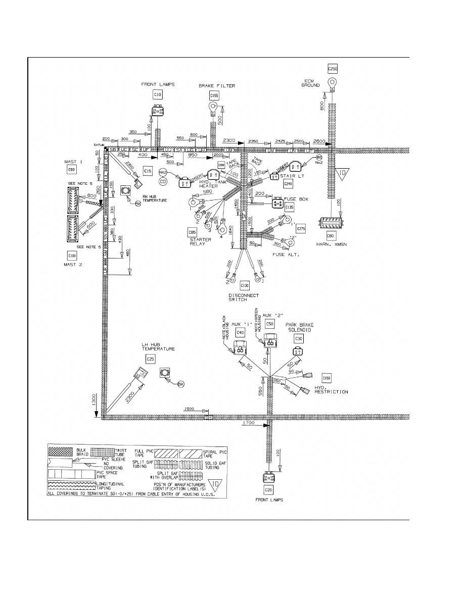
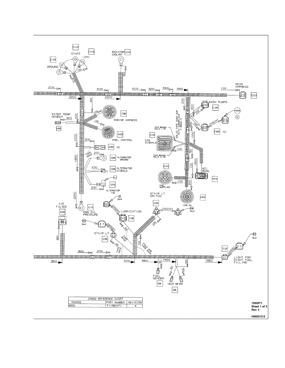
Diagrams, Schematics, or Arrangements
Figure 7. Main Wire Harness
13

NOTES
____________________________________________________________
____________________________________________________________
____________________________________________________________
____________________________________________________________
____________________________________________________________
____________________________________________________________
____________________________________________________________
____________________________________________________________
____________________________________________________________
____________________________________________________________
____________________________________________________________
____________________________________________________________
____________________________________________________________
____________________________________________________________
____________________________________________________________
____________________________________________________________
____________________________________________________________
____________________________________________________________
____________________________________________________________
____________________________________________________________
14


TECHNICAL PUBLICATIONS
2200 SRM 1119
8/04 (7/04) Printed in United Kingdom
Document Outline
- toc
Wyszukiwarka
Podobne podstrony:
910110 2200SRM0143 (08 2004) UK EN
1565183 2200SRM1110 (08 2004) UK EN
1538373 2200SRM1065 (02 2004) UK EN
1559550 2200SRM1097 (10 2004) UK EN
910030 1400SRM0047 (08 2004) UK EN
1494143 2200SRM0939 (12 2004) UK EN
1519772 2200SRM1016 (10 2004) UK EN
897495 2200SRM0514 (01 2004) UK EN
1566270 0100SRM1118 (08 2004) UK EN
1564268 2200SRM1106 (01 2004) UK EN
1565181 2000SRM1108 (08 2004) UK EN
897409 2200SRM0460 (08 1995) UK EN
1556871 2200SRM1105 (01 2004) UK EN
więcej podobnych podstron