HYDRAULIC PLATE
H40.00-52.00XM-16CH
(H1050, 1150HD-CH) [E117]
PART NO. 1565181
2000 SRM 1108

SAFETY PRECAUTIONS
MAINTENANCE AND REPAIR
• When lifting parts or assemblies, make sure all slings, chains, or cables are correctly
fastened, and that the load being lifted is balanced. Make sure the crane, cables, and
chains have the capacity to support the weight of the load.
• Do not lift heavy parts by hand, use a lifting mechanism.
• Wear safety glasses.
• DISCONNECT THE BATTERY CONNECTOR before doing any maintenance or repair
on electric lift trucks. Disconnect the battery ground cable on internal combustion lift
trucks.
• Always use correct blocks to prevent the unit from rolling or falling. See HOW TO PUT
THE LIFT TRUCK ON BLOCKS in the Operating Manual or the Periodic Mainte-
nance section.
• Keep the unit clean and the working area clean and orderly.
• Use the correct tools for the job.
• Keep the tools clean and in good condition.
• Always use HYSTER APPROVED parts when making repairs. Replacement parts
must meet or exceed the specifications of the original equipment manufacturer.
• Make sure all nuts, bolts, snap rings, and other fastening devices are removed before
using force to remove parts.
• Always fasten a DO NOT OPERATE tag to the controls of the unit when making repairs,
or if the unit needs repairs.
• Be sure to follow the WARNING and CAUTION notes in the instructions.
• Gasoline, Liquid Petroleum Gas (LPG), Compressed Natural Gas (CNG), and Diesel fuel
are flammable. Be sure to follow the necessary safety precautions when handling these
fuels and when working on these fuel systems.
• Batteries generate flammable gas when they are being charged. Keep fire and sparks
away from the area. Make sure the area is well ventilated.
NOTE: The following symbols and words indicate safety information in this
manual:
WARNING
Indicates a condition that can cause immediate death or injury!
CAUTION
Indicates a condition that can cause property damage!

Hydraulic Plate
Table of Contents
TABLE OF CONTENTS
General ...............................................................................................................................................................
Description and Operation ................................................................................................................................
Hydraulic Oil Supply.....................................................................................................................................
Manifold, Section 1 of Hydraulic Plate.........................................................................................................
Main Control Valve, Section 2 of Hydraulic Plate .......................................................................................
Description.................................................................................................................................................
Operation ...................................................................................................................................................
Auxiliary Section...................................................................................................................................
Tilt Section ............................................................................................................................................
Lift Section ............................................................................................................................................
Return Manifold, Section 3 of Hydraulic Plate ............................................................................................
Brake Manifold, Section 4 of Hydraulic Plate..............................................................................................
Cooling Circuit...........................................................................................................................................
Service Brake.............................................................................................................................................
Parking Brake ...........................................................................................................................................
Flow Amplifier, Section 5 of Hydraulic Plate ...............................................................................................
Manifold, Section 1 of Hydraulic Plate .............................................................................................................
General ...........................................................................................................................................................
Valves and Pressure Switches.......................................................................................................................
Main Control Valve, Section 2 of Hydraulic Plate............................................................................................
Remove ...........................................................................................................................................................
Disassemble ...................................................................................................................................................
Auxiliary Section .......................................................................................................................................
Lift Section.................................................................................................................................................
Lift/Tilt Section..........................................................................................................................................
Clean and Inspect ..........................................................................................................................................
Assemble ........................................................................................................................................................
Auxiliary Section .......................................................................................................................................
Lift Section.................................................................................................................................................
Lift/Tilt Section..........................................................................................................................................
Install .............................................................................................................................................................
Return Manifold, Section 3 of Hydraulic Plate ................................................................................................
Remove ...........................................................................................................................................................
Disassemble ...................................................................................................................................................
Clean and Inspect ..........................................................................................................................................
Assemble ........................................................................................................................................................
Install .............................................................................................................................................................
Brake Manifold, Section 4 of Hydraulic Plate ..................................................................................................
Remove ...........................................................................................................................................................
Clean and Inspect ..........................................................................................................................................
Install .............................................................................................................................................................
Flow Amplifier, Section 5 of Hydraulic Plate ...................................................................................................
Hydraulic Hose Repair ......................................................................................................................................
Hydraulic Hose Identification ...........................................................................................................................
Torque Values .....................................................................................................................................................
Measurements and Adjustments ......................................................................................................................
Measurements ...............................................................................................................................................
Adjustments ...................................................................................................................................................
Troubleshooting..................................................................................................................................................
Diagrams, Schematics, or Arrangements .........................................................................................................
Figure 12. Hydraulic Schematic...............................................................................................................
©2004 HYSTER COMPANY
i

Table of Contents
Hydraulic Plate
TABLE OF CONTENTS (Continued)
This section is for the following models:
H40.00-52.00XM-16CH (H1050, 1150HD-CH) [E117]
ii
2000 SRM 1108
General
General
This section has the description and operation of
the hydraulic components that are assembled on the
Hydraulic Plate. The section also has disassembly,
assembly, repair, calibration, and troubleshooting
for most components that are assembled on the
Hydraulic Plate.
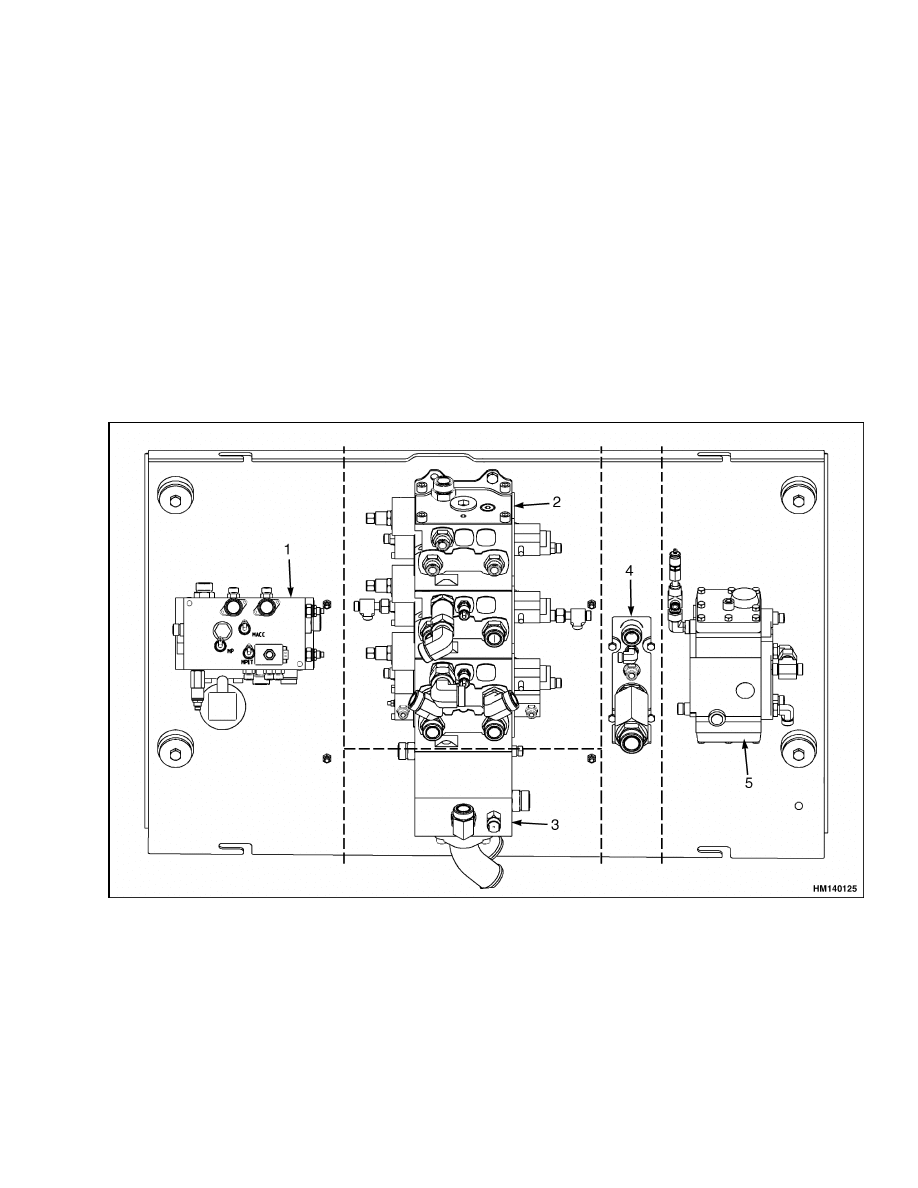
The five sections of the Hydraulic Plate are as follows
(see Figure 1):
• Section 1 contains the manifold with most of the
hydraulic system valves and test ports.
• Section 2 contains the main control valve.
• Section 3 contains the return manifold.
• Section 4 contains brake manifold.
• Section 5 contains the flow amplifier.
The Hydraulic Plate is an integral part of the total
hydraulic system. See the following sections for de-
scription, operation, and repair information of hy-
draulic components in these systems:
Hydraulic System 1900 SRM 1102
Steering System 1600 SRM 1109
Parking Brake 1800 SRM 1117
Service Brake 1800 SRM 1038
Mast 4000 SRM 1160
Hydraulic Gear Pumps 1900 SRM 97
Tilt Cylinders 2100 SRM 1116
Extendable Container Attachment 5000 SRM
723
1.
MANIFOLD SECTION
2.
MAIN CONTROL VALVE SECTION
3.
RETURN MANIFOLD SECTION
4.
BRAKE MANIFOLD SECTION
5.
FLOW AMPLIFIER SECTION
Figure 1. Hydraulic Plate Sections
1

Description and Operation
2000 SRM 1108
Description and Operation
HYDRAULIC OIL SUPPLY
Two gear pumps supply the flow of oil for the com-
ponents of the hydraulic system. These pumps are
driven by a gear arrangement in the torque converter
housing. The inlet hose for each gear pump is con-
nected to the hydraulic tank with a manual shutoff
valve.
The cover end section of the right-hand tandem pump
supplies oil to the accumulator charge valve for the
brake pilot system, auxiliary section, and lift section.
The shaft end section of this tandem pump supplies
oil for the single spool main control valve (lift sec-
tion).
The cover end section of the left-hand tri-section
pump circulates oil in tank through heat exchanger
circuit and oil-cooled brakes. The shaft end section of
this pump supplies oil to flow amplifier for steering
system. Oil that is not needed for steering flows from
flow amplifier to the two spool main control valve
(tilt/lift section). When the operator is not steering,
all of oil from pump flows to main control valve.
NOTE: Oil that is returned to the hydraulic tank is
filtered.
MANIFOLD, SECTION 1 OF HYDRAULIC
PLATE
The relief valve limits input oil pressure supplied
to accumulator charge valve to 28 MPa (4061 psi),
and forces oil to flow through a high pressure oil
filter (20 micron), if oil is needed to charge the ac-
cumulator. See Figure 2. The accumulator charge
valve controls charging rate and pressure of oil in
the accumulator for brake/pilot system. The accu-
mulator charge valve stops charging when accumu-
lator pressure reaches upper limit. See Measure-
ments and Adjustments. When accumulator pres-
sure reaches lower limit, see Measurements and Ad-
justments, the accumulator charge valve allows oil
from pump to charge accumulator. Adjustment at
the spring of check valve in accumulator charge valve
sets high and low limit pressure at accumulator. This
pressure can be measured at check port MACC.
Oil pressure from accumulator is supplied to brake
treadle. The right-hand pedal only activates the ser-
vice brakes. The left-hand pedal first disengages the
transmission, then the service brakes will be acti-
vated. Both pedals will engage the brake pressure
switch to operate the stop lights. For brake trea-
dle pressures, see Measurements and Adjustments.
Brake pressure can be measured at check port MSB4.
Oil pressure from accumulator is also supplied to the
pressure switch that operates the warning light in
event of low brake pressure and to the solenoid valve
for the parking brake. Both are integrated in the cab
manifold. See Figure 2. The solenoid valve can be op-
erated by a switch located on the instrument panel.
The solenoid valve is normally energized during op-
eration for oil pressure to compress the spring to re-
lease parking brake. For further information on the
brake circuit, see the section Service Brake 1800
SRM 1038.
The reducer valve for the pilot is set at 5 MPa
(725 psi) and controls the pressure and supply of hy-
draulic oil to pilot circuits for remote control valves
for lift, tilt, and auxiliary. See Figure 2. The setting
can be checked at check port MPLT.
MAIN CONTROL VALVE, SECTION 2 OF
HYDRAULIC PLATE
Description
The main control valve controls the operation of the
lift (2 sections), tilt and auxiliary cylinders. See Fig-
ure 3. The main control valve is fastened to a plate
in the frame. The valve is also divided into a lift/tilt
section, lift section and auxiliary section. Every sec-
tion has it’s own primary relief valve, set on 23.5 MPa
(3410 psi). The tilt section has an impact relief valve,
set on 25 MPa (3625 psi), which is activated during
contact and opens a tank line to allow the mast to tilt
backward.
Each section of the valve has a spool and valve body.
On the fork lift truck, the control spools for the tilt
and auxiliary are the same, however a different type
of spool is used in the lift section of the valve. All
spools have metering notches to improve the control
of oil flow. When a lever is operated, a pilot pres-
sure is generated and activates the end of a spool.
Each spool has springs that return the spool to the
NEUTRAL position as soon as the control lever is
released. The spring package is different in every
section.
2

2000 SRM 1108
Description and Operation
Operation
The main control valve controls the lift, tilt, and aux-
iliary functions. In these valves, the spools can be op-
erated without preventing the flow of oil to the other
spools.
The two-spool section (tilt/lift section) of the main
control valve receives oil from the flow amplifier of
the steering system. The single spool (lift section) re-
ceives oil directly from the hydraulic pump (tandem).
The main control valve has four passages through
each section. When the spools are in the NEUTRAL
position, the oil flows through the open-center pas-
sage and returns to the hydraulic tank.
A spool
makes a restriction in the open-center passage when
the spool is moved from the NEUTRAL position.
This restriction causes an increase in pressure in the
parallel passage. This passage is common to all sec-
tions of the valve, but oil cannot flow freely through
it. The pressure in the parallel passage causes the
oil to flow through the check valve into a supply
cavity in the valve body. The spool opens a path
from the supply cavity to the hydraulic cylinders to
do work, and also opens the tank line.
Auxiliary Section
The single spool control valve will, depending on the
function selected by the operator, cause either out-
put Aux A or output Aux B to supply hydraulic oil to
carriage/attachment. When output Aux A supplies
the oil, the solenoid valve provides the return to
hydraulic tank. When output Aux B supplies the oil,
the solenoid valve provides the return to the tank.
When no function is selected by the operator, both
solenoid valves provide return to hydraulic tank.
Oil that is not used to operate auxiliary functions is
added to the flow of the lift functions. The pressure
of the oil of the single spool main control valve can
be checked at check port MP.
Tilt Section
Each port in the tilt section of the single spool con-
trol valve is connected to the tilt cylinders. When
the spool is moved to the forward tilting position,
the spool makes a restriction in the open-center pas-
sage. The increased pressure in the parallel passage
causes oil to flow to the tilt cylinders and pressure
to the impact relief valve. The impact relief valve is
set on 25 MPa (3625 psi) and will be activated dur-
ing contact. This allows the operator to tilt the mast
backwards. When the spool is in the backward tilt-
ing position, the spool opens the paths from the tilt
cylinders to the hydraulic tank. Tilt lock relief valves
prevents the mast from tilting forward too fast by
keeping some back pressure at the rod ends of the
tilt cylinders. The pressure of the oil of the two-spool
main control valve can be checked at check port M3.
Lift Section
Each port in the lift section of the control valve is con-
nected to the lift cylinders. The main control valve
has two lift sections, and will not start together. One
section is delayed. See Figure 3. When the spool is
moved to the LIFT position, the spool makes a re-
striction in the open-center passage. The increases
pressure in the parallel passage causes oil to flow
through the check valve to the supply cavity. When
the spool is in the LOWER position, the spool opens
the paths from the lift cylinders to the drain cav-
ity. The maximum LOWER speed is controlled by
the lower control valves in the lift cylinders.
Oil
from the pump can flow through the open-center pas-
sage when the spool is in the LOWER position or the
NEUTRAL position. The NEUTRAL position of the
spool closes the passages to the ports for the lift cylin-
ders.
The pressure of the oil of the single spool main control
valve can be checked at check port M2.
RETURN MANIFOLD, SECTION 3 OF
HYDRAULIC PLATE
The return manifold regulates and directs the flow
of oil from all components to the hydraulic plate and
the cab manifold to the hydraulic tank, except cooling
flow of the brakes. See Figure 3.
Two hydraulic lines are connected from the return
manifold to the hydraulic tank. Oil from the man-
ifold returns through two filters (10 micron) with a
maximum pressure of 300 kPa (43.5 psi) to the hy-
draulic tank.
3
Description and Operation
2000 SRM 1108
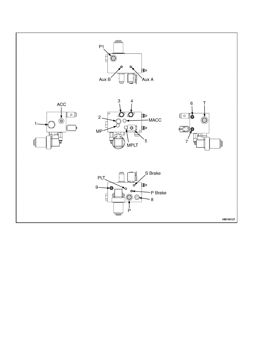
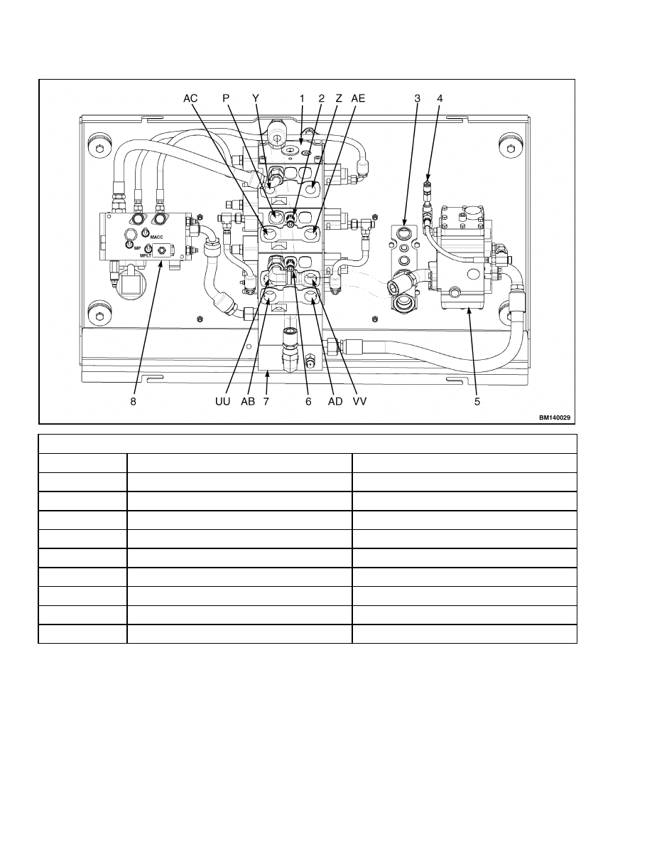
Figure 2. Manifold
4
2000 SRM 1108
Description and Operation
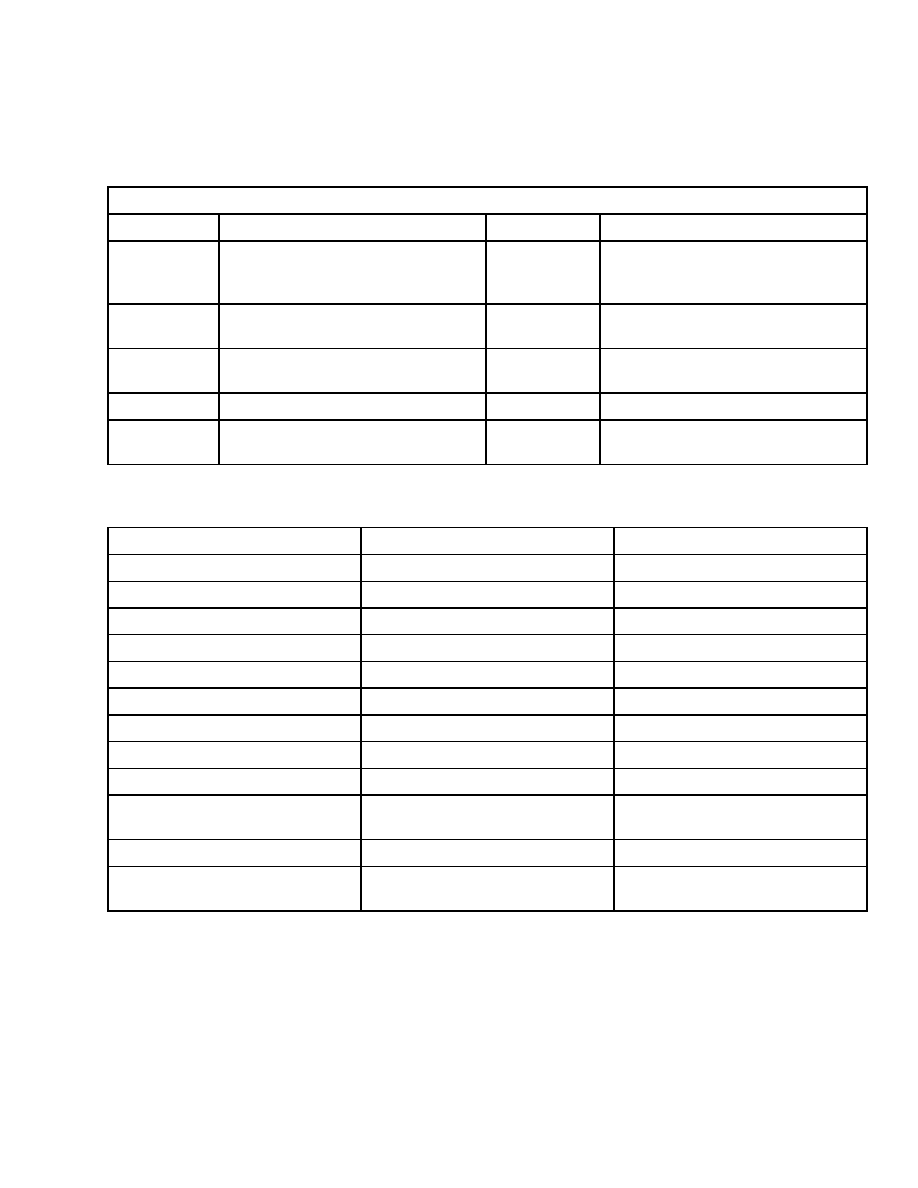
Legend for Figure 2
NOTE: THE FOLLOWING TABLE INDICATES HYDRAULIC CONNECTIONS TO/FROM THE MANIFOLD. LETTER-
ING IN PARENTHESIS INDICATES LOCATION AND IS STAMPED ON MANIFOLD.
Hydraulic Line Connections
Location
Connection
Location
Connection
ACC
To/From Accumulator
P1
Pump Supply to Single Spool
Control Valve (oil supply for
auxiliary functions)
Aux A
To Single Spool Control Valve (pilot
pressure for auxiliary functions)
P Brake
Park Brake Pressure Supply
To Brake Manifold
Aux B
To Single Spool Control Valve (pilot
pressure for auxiliary functions)
S Brake
Service Brake Pressure Supply
To Cab Manifold
P
Pump Supply From Gear Pump
T
To Return Manifold
PLT
Pilot Supply To cab manifold
(lift/tilt control lever)
NOTE: ITEMS 1 THROUGH 9 ARE VALVES, MEASUREMENT PORTS, AND PRESSURE SWITCHES. NUMBERS
IN PARENTHESIS INDICATE LOCATION AND ARE STAMPED ON MANIFOLD.
Item
Description
Stamping on Manifold
1
6.9 Pressure Maintaining Valve
(1.02)
2
Check Valve
(1.09)
3
3-way Directional Control Valve
(1.15)
4
3-way Directional Control Valve
(1.16)
5
3-way Directional Control Valve
(1.14)
6
Pilot Reducing Valve
(1.13)
7
Brake Reducing Valve
(1.12)
8
Main Relief Valve
(1.04)
9
Charger Valve
(1.10)
MACC
Check Port MACC for
Accumulator Pressure
M ACC
MP
Check Port MP for Pump Pressure
M P
MPLT
Check Port MPLT for Pilot
Pressure
M PLT
5
Description and Operation
2000 SRM 1108
Main Control Valve Connections
Line
Connection
Function
(AB)
To Lift/Tilt Manifold
Lift/Lower
(AC)
To Lift/Tilt Manifold
Lift/Lower
(AD)
To Lift/Tilt Manifold
Lift/Lower
(AE)
To Lift/Tilt Manifold
Lift/Lower
(UU)
To Lift/Tilt Manifold
Tilt
(VV)
To Lift/Tilt Manifold
Tilt
(Y)
To Lift/Tilt Manifold
Auxiliary
(Z)
To Lift/Tilt Manifold
Auxiliary
(P)
From Gear Pump
Oil Supply
1.
MAIN CONTROL VALVE
2.
CHECK PORT M2
3.
BRAKE MANIFOLD
4.
CHECK PORT M1
5.
FLOW AMPLIFIER
6.
CHECK PORT M3
7.
RETURN MANIFOLD
8.
MAIN MANIFOLD
Figure 3. Hydraulic Plate Layout
6

2000 SRM 1108
Description and Operation
BRAKE MANIFOLD, SECTION 4 OF
HYDRAULIC PLATE
The brake manifold regulates and directs the flow of
oil for the brake cooling circuit, service brake, and
parking brake.
Cooling Circuit
Cooling oil for the oil-cooled brakes comes from the
cover end 48 cm
3
(2.94 in.
3
) tri-section pump. This
oil flows through the thermostatic bypass valve to the
service brakes at each drive wheel. If the oil is above
70 C (158 F), the valve will direct the oil through the
air-to-oil heat exchanger before it goes to the brakes.
A check valve keeps the pressure in the brake as-
semblies to less than 140 kPa (20 psi). Oil from the
brakes returns through a filter (20 micron), with a
35 kPa (5 psi) bypass, to the hydraulic tank.
Service Brake
Oil for activating the service brake comes from the
cab manifold. The service brake pedal (treadle valve)
controls the pressure of the oil to the service brake
piston at each drive wheel.
The pressure of the hydraulic oil supplied to the
brake manifold can be checked at check port MSB4,
integrated in the cab manifold.
The hydraulic line also functions as a return line
when the brake treadle is not operated. Oil flows
back through the brake treadle and return manifold
to the hydraulic tank.
Parking Brake
Oil for releasing the parking brake comes from the
main manifold.
An electrical signal triggers the parking brake valve.
The parking brake valve position changes, and oil
pressure in the parking brake cylinder is relieved.
The spring pressure automatically applies the brake
if the system loses oil pressure.
FLOW AMPLIFIER, SECTION 5 OF
HYDRAULIC PLATE
The flow amplifier regulates and directs flow of oil
to the steering cylinder. See Figure 3 and Figure 12.
The flow amplifier increases oil flow five times more
than pilot input flow from steering control unit. The
rate of oil flow to steering cylinder is directly propor-
tional to rate of pilot flow from steering control unit.
The flow amplifier receives oil from the, 118 cm
3
(7.20 in.
3
), per revolution pump. When there is no
steering demand, the priority valve in the flow am-
plifier allows oil to flow from pump to main control
valve. The pressure of hydraulic oil supplied to am-
plifier can be checked at check port M7. For further
information, see the section Steering System 1600
SRM 1109.
7

Manifold, Section 1 of Hydraulic Plate
2000 SRM 1108
Manifold, Section 1 of Hydraulic Plate
GENERAL
All pressure switches, valves, and other associated
items installed on the manifold can be replaced. Be-
fore removal of any part, check that the area is clean
and protected against dirt and fluid contamination.
NOTE: It is not necessary to remove the manifold
to replace manifold components. Only remove the
manifold from the mounting plate when the whole
component is to be replaced.
WARNING
Never work under a raised carriage or forks.
Lower the carriage or use blocks and chains on
the mast weldments and carriage so that they
cannot move. Verify the moving parts are at-
tached to parts that do not move.
Some parts have compressed springs under
them that can have enough force to cause dam-
age or injury. Always use caution and wear eye
protection when removing parts.
Before removing any hydraulic components or
disconnecting any hydraulic lines, release the
hydraulic pressure from the hydraulic circuit
as follows:
• Shut engine OFF and completely lower car-
riage. Install blocks at wheels to prevent lift
truck from moving.
• Release the accumulator pressure by operat-
ing the brake pedal.
The manifold (see Figure 2) is an integral part of the
Hydraulic Plate. For more information on the repairs
to all parts of the Hydraulic Plate, see the section
Hydraulic System 1900 SRM 1102.
VALVES AND PRESSURE SWITCHES
WARNING
Cleaning solvents can be flammable and toxic.
Cleaning solvents can also cause skin irrita-
tion. When using cleaning solvents, always fol-
low the solvent manufacturer’s recommended
safety precautions.
NOTE: Only use plugs that have been cleaned in sol-
vent.
NOTE: In the event that seals are missing, check
manifold for missing seals and remove.
NOTE: Cartridge valves and switches are not field-
serviceable with exception of external seals and elec-
trical solenoids. In event of a defective component,
completely replace valve of switch.
NOTE: Check manifold for cracks. If there are cracks
in manifold, the manifold should be replaced.
The valves and pressure switch seals are serviceable
parts of the manifold. Use the following procedures
for repair:
1.
Unscrew the cartridge valve of switch from man-
ifold.
2.
Check that all seals are attached to cartridge
valve or switch.
3.
Install a temporary plug in place of cartridge
valve or switch.
4.
Clean cartridge valve or switch in solvent and
inspect component for damage.
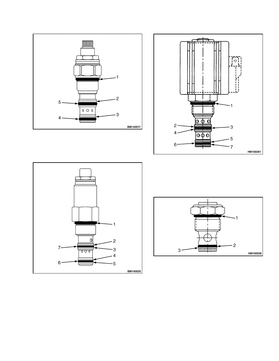
5.
Install new seals. For correct order of backup
rings and O-rings. See Figure 4, Figure 5, Fig-
ure 6, Figure 7, and Figure 8.
6.
Lubricate component/valve with clean hydraulic
oil before installation.
7.
Remove temporary plug.
8.
Install and torque component/valve or switch to
value listed in Torque Values.
8
2000 SRM 1108
Manifold, Section 1 of Hydraulic Plate
1.
O-RING
2.
BACKUP RING
3.
BACKUP RING
4.
O-RING
5.
O-RING
Figure 4. Reducing Valve Cartridge (1.12/1.13)
1.
O-RING
2.
BACKUP RING
3.
BACKUP RING
4.
BACKUP RING
5.
BACKUP RING
6.
O-RING
7.
O-RING
Figure 5. Charger Valve Cartridge (1.10)
1.
O-RING
2.
BACKUP RING
3.
O-RING
4.
BACKUP RING
5.
BACKUP RING
6.
O-RING
7.
BACKUP RING
Figure 6. Solenoid Control Valve Cartridge
(1.14)
1.
O-RING
2.
O-RING
3.
BACKUP RING
Figure 7. Check Valve Cartridge (1.09)
9
Manifold, Section 1 of Hydraulic Plate
2000 SRM 1108
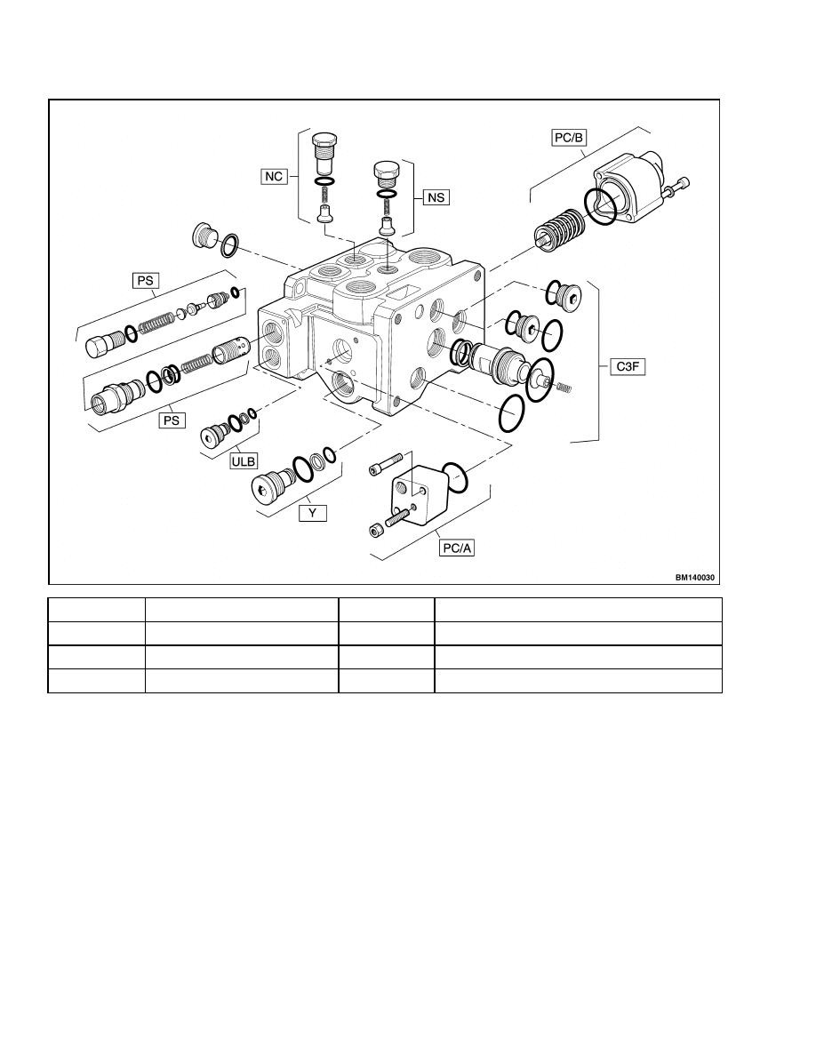
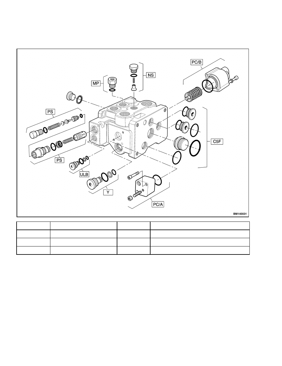
NC
Check Valve, Common
PC/A
Spool Actuator
NS
Check Valve, Section
Y
Plug, Relief Cavity
PC/B
Spool Actuator
ULB
Plug, Unloading Cavity
C3F
Flange Kit
PS
Main Relief Valve
Figure 8. Main Control Valve Section (Single Spool for Auxiliary)
10
2000 SRM 1108
Main Control Valve, Section 2 of Hydraulic Plate
Main Control Valve, Section 2 of Hydraulic Plate
REMOVE
WARNING
Lower carriage completely before working on
control valve or hydraulic system.
Do not work under a raised carriage.
Put
mast in a vertical position and lower carriage
completely before disconnecting any parts of
hydraulic system.
The mast can lower sud-
denly and cause injury if the carriage is not
lowered. This procedure will make sure that
the carriage cannot lower suddenly and cause
injury or death.
Proceed as follows:
1.
Place the lift truck on a solid, even, and level
surface.
2.
Shut down the engine.
3.
Put blocks on both sides (front and back) of the
tires to prevent movement of the lift truck.
4.
Turn the key switch to the ON position.
WARNING
Apply brake pedal 10 to 20 times until accumu-
lated hydraulic brake pressure is released.
5.
Turn the key switch to the OFF position.
6.
Close shutoff valves on the bottom of the tank.
7.
Remove the cover on the topside of the frame.
8.
Tag and disconnect electric wires at spools of con-
trol valve.
9.
Put tags for identification on hydraulic lines.
Disconnect the hydraulic lines from the main
control valve. Keep the end of the hose above
the hydraulic tank until a plug is installed in the
hose. Put caps on the open lines, ports, or other
connectors.
NOTE: Only remove the main control valve from
mounting plate when part to be repaired is not
accessible. Disassemble main control valve as nec-
essary for repairs. Most repairs are for replacement
of O-rings.
10. Remove the four bolts that fasten the main con-
trol valve on the hydraulic plate.
WARNING
The main control valve weighs approximately
65 kg (145 lb) and can cause serious injury if
the control valve is not lifted properly or falls.
Verify that the main control valve has proper
support before removing the mounting bolts.
Use a lifting device to remove the main control
valve, and verify that the main control valve is
secure and cannot fall out of the lifting device.
11. Remove the control valve from the hydraulic
plate.
DISASSEMBLE
1.
To remove a spool, remove end cap from valve
section. Carefully pull spool from valve section.
Keep the spring package together.
Put tags
on spools that are removed.
Spools must be
installed in the sections from which they are
removed.
2.
Remove seal retainer for top of spool. Remove
O-rings and wipers from both ends of the section
of the valve and spring packages.
NOTE: The main control valve is divided into a lift/tilt
section, lift section, and auxiliary section. Each sec-
tion has a different spool or spools, and spring pack-
ages.
3.
Remove auxiliary section, lift section, and lift/tilt
section as follows:
Auxiliary Section
CAUTION
Make sure to protect machined surfaces for
O-rings when the sections are separated. Small
defects can cause leaks.
1.
Place the main control valve on a clean and level
surface.
2.
Loosen the four nuts. See Figure 9.
3.
Carefully remove the four nuts and bolts.
11
Main Control Valve, Section 2 of Hydraulic Plate
2000 SRM 1108
4.
Carefully slide the auxiliary section from the lift
section.
5.
Remove O-rings installed between the auxiliary
section and lift section.
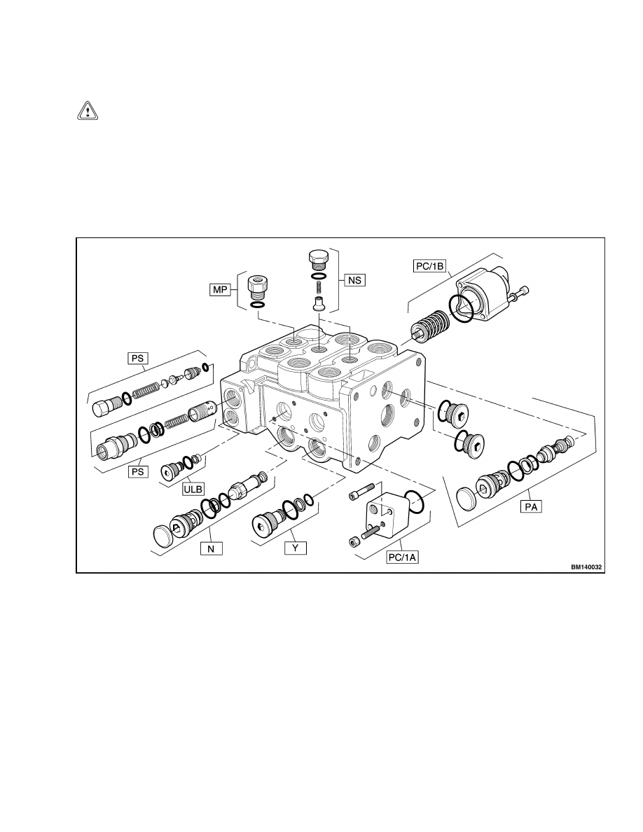
NS
Check Valve, Section
PC/A
Spool Actuator
MP
Check Valve, Check Port
Y
Plug, Relief Cavity
PC/B
Spool Actuator
ULB
Plug, Unloading Cavity
C5F
Flange Kit
PS
Main Relief Valve
Figure 9. Main Control Valve Section (Single Spool for Lift)
12
2000 SRM 1108
Main Control Valve, Section 2 of Hydraulic Plate
Lift Section
CAUTION
Make sure to protect machined surfaces for
O-rings when the sections are separated. Small
defects can cause leaks.
1.
Place the main control valve on a clean and level
surface.
2.
Disassemble the auxiliary section. See Auxiliary
Section.
3.
Loosen the four nuts. See Figure 9 and Figure 10.
4.
Carefully remove the four nuts and bolts.
5.
Carefully slide the lift section from the lift/tilt
section.
6.
Remove O-rings installed between the lift section
and lift/tilt section.
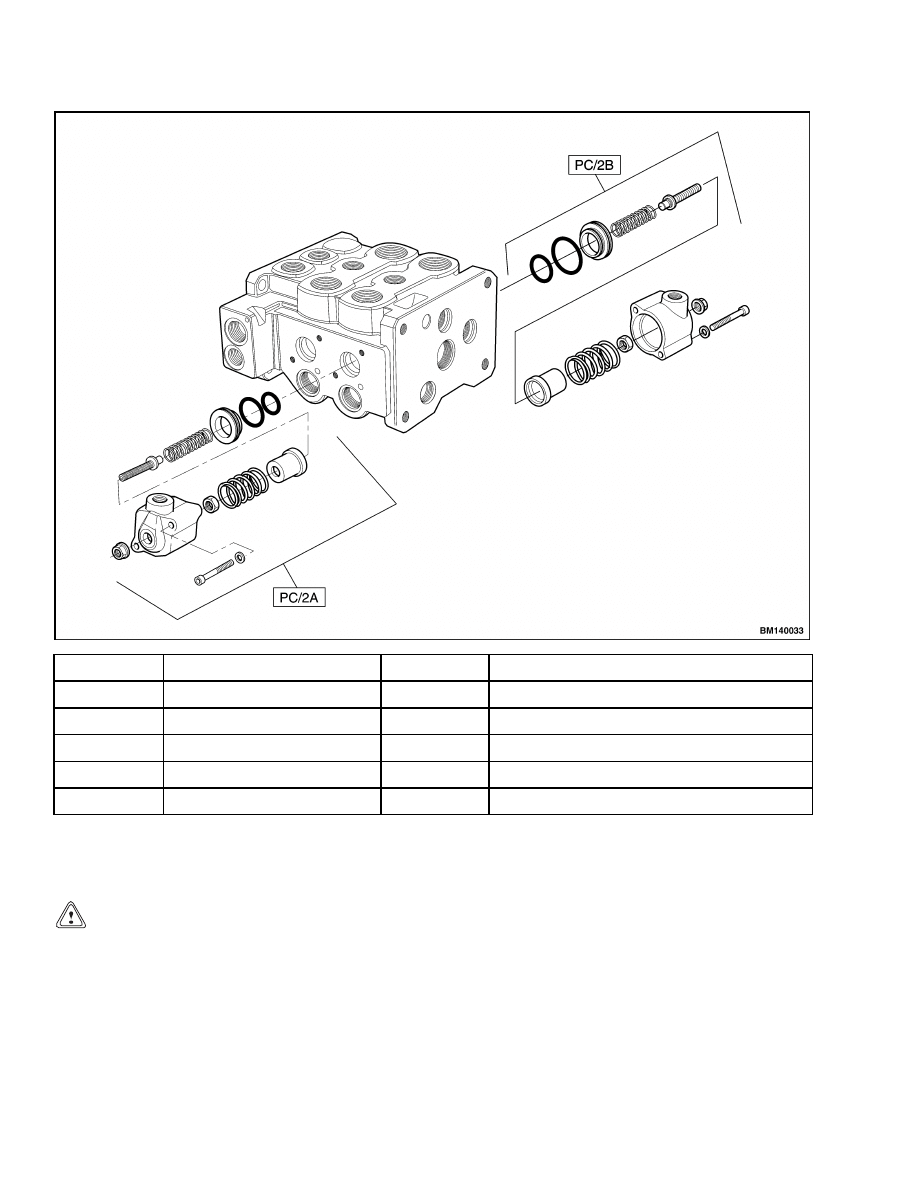
Figure 10. Main Control Valve Section (Two-Spool for Tilt/Lift (Sheet 1 of 2)
13
Main Control Valve, Section 2 of Hydraulic Plate
2000 SRM 1108
Y
Plug, Relief Cavity
MP
Check Valve, Check Port
PA
Plug, Relief Valve
NS
Check Valve, Section
ULB
Plug, Unloading Cavity
PC/1B
Spool Actuator
PS
Main Relief Valve
N
Check Valve, Anti-cavitation
PC/2B
Spool Actuator
PC/1A
Spool Actuator
PC/2A
Spool Actuator
Figure 10. Main Control Valve Section (Two-Spool for Tilt/Lift (Sheet 2 of 2)
Lift/Tilt Section
CAUTION
Make sure to protect machined surfaces for
O-rings when the sections are separated. Small
defects can cause leaks.
1.
Place the main control valve on a clean and level
surface.
2.
Loosen the four nuts. See Figure 9 and Figure 10.
3.
Carefully remove the four nuts and bolts.
4.
Carefully slide the lift/tilt section from the lift
section.
5.
Remove O-rings installed between the lift section
and lift/tilt section.
NOTE: Do not try to repair a relief valve. Replace
the relief valve if it is damaged or cannot be properly
adjusted.
14
2000 SRM 1108
Main Control Valve, Section 2 of Hydraulic Plate
NOTE: For the spool designation, each spool has a
imprinted letter code to facilitate identification dur-
ing tuning or servicing the field.
CLEAN AND INSPECT
WARNING
Cleaning solvents can be flammable and toxic
and can cause skin irritation.
When using
cleaning solvents, always follow the solvent
manufacturer’s recommended safety precau-
tions.
Compressed air can move particles and cause
injury to the user or to other personnel. Make
sure compressed air path is away from all per-
sonnel. Wear eye protection.
1.
Clean all parts of control valve with solvent.
Carefully dry parts with compressed air.
2.
Check spools and bores for defects. If a spool or
bore has damage, replace valve section that has
the damaged part or parts. Make sure that bores
and grooves for O-rings are smooth and do not
have dirt or defects.
3.
Check the check valves and relief valves for dam-
age. Replace valves as necessary.
ASSEMBLE
Auxiliary Section
CAUTION
Before installing parts in valve body, make
sure all parts are clean. Replace all seals and
O-rings.
Lubricate all parts with clean hy-
draulic oil during assembly.
CAUTION
Verify that nuts and bolts torque specifications
are to the values listed. Incorrect torque values
may cause a malfunction of the spools.
1.
Install new seals in bore in each section. See
Figure 9.
2.
Install new O-rings between sections.
3.
Install check valves.
CAUTION
When positioning the sections, do not damage
the O-rings.
4.
Carefully position the auxiliary section in line
with the lift section.
5.
Install nuts, finger tight, on the four bolts.
6.
Torque the four nuts to 80 N•m (59 lbf ft).
7.
Install springs.
8.
Lubricate spools with clean hydraulic oil. Make
sure that dirt does not get on any of the parts.
Carefully install spools in valve body. Make sure
that spools move freely in bores. Install seal re-
tainers and end caps.
Lift Section
CAUTION
Before installing parts in valve body, make
sure all parts are clean. Replace all seals and
O-rings.
Lubricate all parts with clean hy-
draulic oil during assembly.
CAUTION
Verify that bolt torque specifications are to
the values listed. Incorrect torque values may
cause a malfunction of the spools.
1.
Install new seals in bore in each section. See
Figure 9.
2.
Install new O-rings between sections.
3.
Install check valves.
CAUTION
When positioning the sections, do not damage
the O-rings.
4.
Carefully position the lift section in line with the
lift/tilt section.
5.
Install nuts, finger tight, on the four bolts.
6.
Torque the four nuts to 80 N•m (59 lbf ft).
15
Main Control Valve, Section 2 of Hydraulic Plate
2000 SRM 1108
CAUTION
When positioning the sections, do not damage
the O-rings.
7.
Carefully position the auxiliary section in line
with the sub assembled lift section and lift/tilt
section.
8.
Install nuts, finger tight, on the four bolts.
9.
Torque the four nuts to 80 N•m (59 lbf ft).
10. Install springs.
11. Lubricate spools with clean hydraulic oil. Make
sure that dirt does not get on any of the parts.
Carefully install spools in valve body. Make sure
that spools move freely in bores. Install seal re-
tainers and end caps.
Lift/Tilt Section
CAUTION
Before installing parts in valve body, make
sure all parts are clean. Replace all seals and
O-rings.
Lubricate all parts with clean hy-
draulic oil during assembly.
CAUTION
Verify that bolt torque specifications are to
the values listed. Incorrect torque values may
cause a malfunction of the spools.
1.
Install new seals in bore in each section. See
Figure 9.
2.
Install new O-rings between sections.
3.
Install check valves.
CAUTION
When positioning the sections, do not damage
the O-rings.
4.
Carefully position the lift/tilt section in line with
the subassembled auxiliary section and lift sec-
tion.
5.
Install nuts, finger tight, on the four bolts.
6.
Torque the four nuts to 80 N•m (59 lbf ft).
7.
Install springs.
8.
Lubricate spools with clean hydraulic oil. Make
sure that dirt does not get on any of the parts.
Carefully install spools in valve body. Make sure
that spools move freely in bores. Install seal re-
tainers and end caps.
INSTALL
1.
Position the control valve on the hydraulic plate.
2.
Install the four bolts that fasten the control valve
to the hydraulic plate.
3.
Connect electrical cables at solenoids.
4.
Remove caps and connect hydraulic lines to con-
trol valve according to the tags made during re-
moval and Figure 3. Connect return line after
connecting other lines.
5.
Add clean hydraulic oil to tank.
For correct
specifications, see the section Periodic Main-
tenance 8000 SRM 1154.
WARNING
Do not try to locate hydraulic leaks by putting
hands on pressurized hydraulic components.
Hydraulic oil can be injected into the body by
pressure.
CAUTION
Never start the engine with closed shutoff
valves. Open the shutoff valves before starting
the engine to prevent damage to hydraulic
components.
6.
Operate hydraulic system and check for leaks
and correct operation. If necessary, adjust re-
lief valves as described in the section Hydraulic
System 1900 SRM 1102.
7.
Install the cover on the topside of the frame.
16
2000 SRM 1108
Return Manifold, Section 3 of Hydraulic Plate
Return Manifold, Section 3 of Hydraulic Plate
REMOVE
NOTE: One pressure switch and one seal kit are the
repairable parts in the return manifold. See Fig-
ure 1.
WARNING
Lower carriage completely before working on
control valve or hydraulic system.
Do not work under a raised carriage.
Put
mast in a vertical position and lower carriage
completely before disconnecting any parts of
hydraulic system.
The mast can lower sud-
denly and cause injury if the carriage is not
lowered. This procedure will make sure that
the carriage cannot lower suddenly and cause
injury or death.
Proceed as follows:
1.
Place the lift truck on a solid, even, and level
surface.
2.
Shut down the engine.
3.
Put blocks on both sides (front and back) of the
tires to prevent movement of the lift truck.
4.
Turn the key switch to the ON position.
WARNING
Move all control levers back and forth a mini-
mum of 20 times to remove all hydraulic pres-
sure from pilot system.
5.
Turn the key switch to the OFF position.
6.
Close shutoff valves on the bottom of the tank.
7.
Remove the cover on the topside of the frame.
NOTE: Since the return manifold is attached with the
main control valve to the hydraulic plate, the main
control valve also has to be disconnected along with
the return manifold.
NOTE: Only remove the return manifold/main con-
trol valve assembly when the part to be repaired is
not accessible. Disassemble return manifold/main
control valve assembly as necessary for repairs. Most
repairs are for replacement of O-rings.
8.
Tag and disconnect electric wires at spools of con-
trol valve.
9.
Put tags for identification on hydraulic lines.
Disconnect the hydraulic lines from the main
control valve and return manifold. Keep the end
of the hose above the hydraulic tank until a plug
is installed in the hose. Put caps on the open
lines, ports, or other connectors.
WARNING
The assembly weighs approximately 90 kg
(200 lb) and can cause serious injury if the
assembly is not lifted properly or falls. Verify
that the assembly has proper support before
removing the mounting bolts.
Use a lifting
device to remove the assembly, and verify that
the assembly is secure and cannot fall out of
the lifting device.
10. Remove the four bolts that fasten the assembly
on the hydraulic plate.
11. Remove assembly from the hydraulic plate.
DISASSEMBLE
CAUTION
Make sure to protect machined surfaces for
O-rings when the sections are separated. Small
defects can cause leaks.
1.
Place the return manifold/main control valve as-
sembly on a clean and level surface.
2.
Loosen the four bolts.
3.
Carefully remove the four bolts.
4.
Remove the O-rings installed between the return
manifold and the lift/tilt section (main control
valve).
17
Return Manifold, Section 3 of Hydraulic Plate
2000 SRM 1108
CLEAN AND INSPECT
WARNING
Cleaning solvents can be flammable and toxic
and can cause skin irritation.
When using
cleaning solvents, always follow the solvent
manufacturer’s recommended safety precau-
tions.
Compressed air can move particles and cause
injury to the user or to other personnel. Make
sure compressed air path is away from all per-
sonnel. Wear eye protection.
Clean all parts in solvent and dry the parts with com-
pressed air. Inspect the bores for damage. If there
are scratches or other damage, the manifold must
be replaced. Inspect the fittings, O-rings, and check
valve for damages. Replace damaged parts.
ASSEMBLE
CAUTION
Before installing parts in valve body, make
sure all parts are clean. Replace all seals and
O-rings.
Lubricate all parts with clean hy-
draulic oil during assembly.
1.
Install new O-rings between sections.
CAUTION
When positioning sections, do not damage
O-rings.
2.
Carefully position the return manifold in line
with the main control valve.
3.
Install the four bolts, finger tight.
4.
Torque the four bolts to 80 N•m (59 lbf ft).
INSTALL
1.
Position the assembly on the hydraulic plate.
2.
Install the four bolts that fasten the assembly to
the hydraulic plate.
3.
Connect the electrical cables at the solenoids on
the main control valve.
4.
Remove the caps and connect the hydraulic lines
to the assembly according to the tags made dur-
ing removal and Figure 3. Connect the return
lines after connecting the other lines.
5.
Add clean hydraulic oil to the tank. For correct
specifications, see the section Periodic Mainte-
nance 8000 SRM 1154.
WARNING
Do not try to locate hydraulic leaks by putting
hands on pressurized hydraulic components.
Hydraulic oil can be injected into the body by
pressure.
CAUTION
Never start the engine with closed shutoff
valves. Open the shutoff valves before starting
the engine to prevent damage to hydraulic
components.
6.
Start the engine and operate the hydraulic sys-
tem.
Check that the functions of the return
manifold and main control valve work correctly.
Check for leaks.
7.
Install the cover on the topside of the frame.
18
2000 SRM 1108
Brake Manifold, Section 4 of Hydraulic Plate
Brake Manifold, Section 4 of Hydraulic Plate
REMOVE
NOTE: There are no repairable parts in the brake
manifold. The brake manifold is a one-piece, spe-
cial made product. If there is a malfunction with the
manifold, replace the manifold. See Figure 1.
WARNING
Lower carriage completely before working on
control valve or hydraulic system.
Do not work under a raised carriage.
Put
mast in a vertical position and lower carriage
completely before disconnecting any parts of
hydraulic system.
The mast can lower sud-
denly and cause injury if the carriage is not
lowered. This procedure will make sure that
the carriage cannot lower suddenly and cause
injury or death.
Proceed as follows:
1.
Shut down the engine.
2.
Turn the key switch to the ON position.
WARNING
Move all control levers back and forth a mini-
mum of 20 times to remove all hydraulic pres-
sure from pilot system.
3.
Turn the key switch to the OFF position.
4.
Close the shutoff valves on the bottom of the
tank.
5.
Remove the cover on the topside of the frame.
6.
Put tags for identification on the hydraulic lines.
Disconnect the hydraulic lines from the brake
manifold. Put caps on the open lines, ports, or
other connectors.
7.
Remove the four bolts that fasten the brake man-
ifold to the hydraulic plate.
8.
Remove the brake manifold from the hydraulic
plate.
CLEAN AND INSPECT
WARNING
Cleaning solvents can be flammable and toxic
and can cause skin irritation.
When using
cleaning solvents, always follow the solvent
manufacturer’s recommended safety precau-
tions.
Compressed air can move particles and cause
injury to the user or to other personnel. Make
sure compressed air path is away from all per-
sonnel. Wear eye protection.
1.
Clean all parts with solvent and carefully dry the
parts with compressed air.
2.
Inspect the bores for damage.
If there are
scratches or other damage, the manifold must
be replaced.
3.
Inspect the fittings, O-rings, and check valve for
damage. Replace damaged parts.
INSTALL
1.
Position the brake manifold on the hydraulic
plate.
2.
Install the four bolts that fasten the brake man-
ifold to the hydraulic plate.
3.
Remove caps and connect hydraulic lines to
brake manifold according to the tags made dur-
ing removal and Figure 3. Connect return line
after connecting other lines.
4.
Add clean hydraulic oil to tank.
For correct
specifications, see the section Periodic Main-
tenance 8000 SRM 1154.
19
Hydraulic Hose Identification
2000 SRM 1108
WARNING
Do not try to locate hydraulic leaks by putting
hands on pressurized hydraulic components.
Hydraulic oil can be injected into the body by
pressure.
CAUTION
Never start the engine with closed shutoff
valves. Open the shutoff valves before starting
the engine to prevent damage to hydraulic
components.
5.
Start the engine and operate the hydraulic sys-
tem. Check that the functions of the brake man-
ifold work correctly. Check for leaks.
6.
Install the cover on the topside of the frame.
Flow Amplifier, Section 5 of Hydraulic Plate
The flow amplifier regulates and directs the flow of oil to the steering system. See Figure 3. For the removal,
cleaning, inspection, assembly, and installation of the flow amplifier, see the section Steering System 1600
SRM 1109.
Hydraulic Hose Repair
When the lift truck is used in dirty conditions, it is recommended to replace hoses every 5 years or 10,000 hours
of service regardless of condition.
Hydraulic Hose Identification
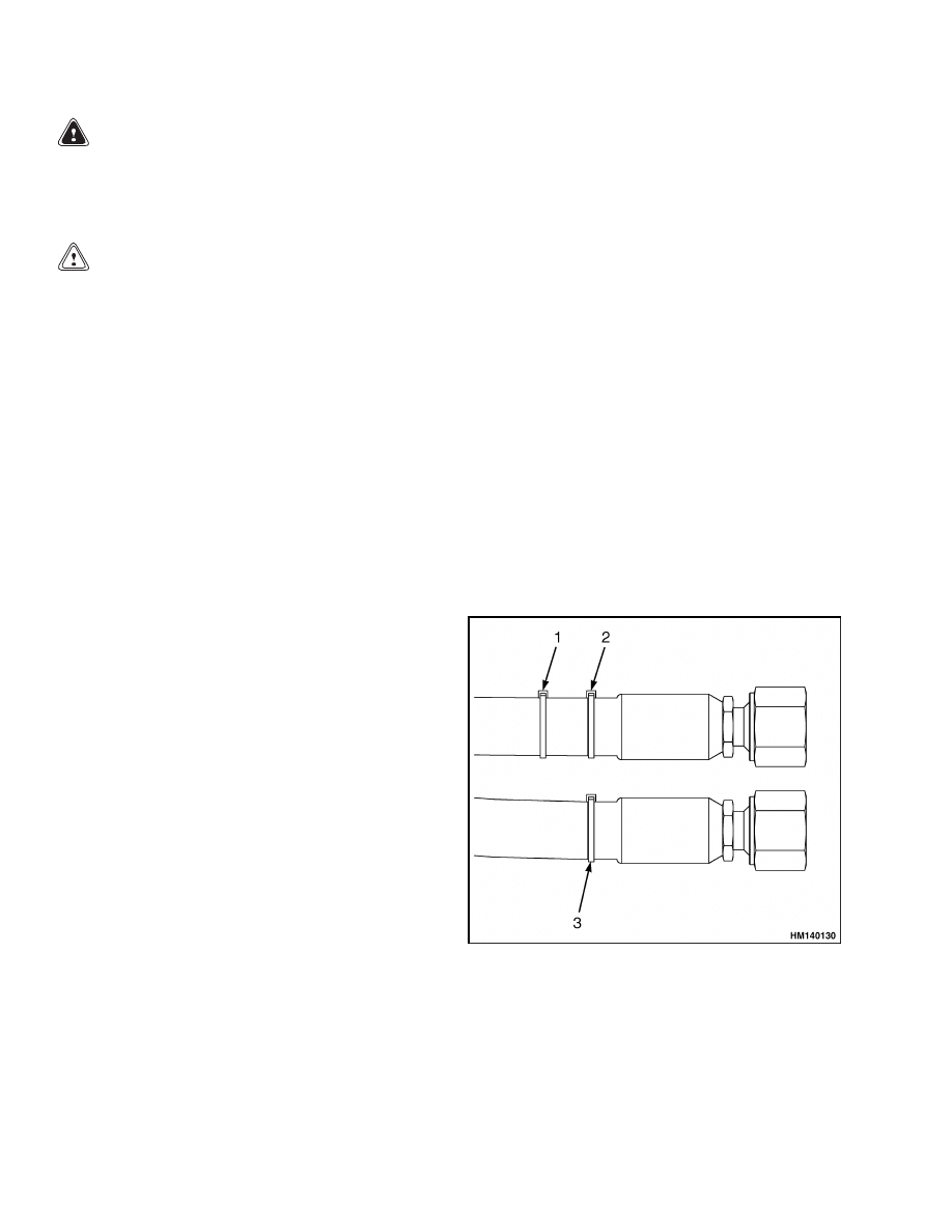
For correct hose routing and function recognition,
several hoses are provided with colored straps.
Hoses can be divided by hoses with one strap and
hoses with two straps. See Figure 11.
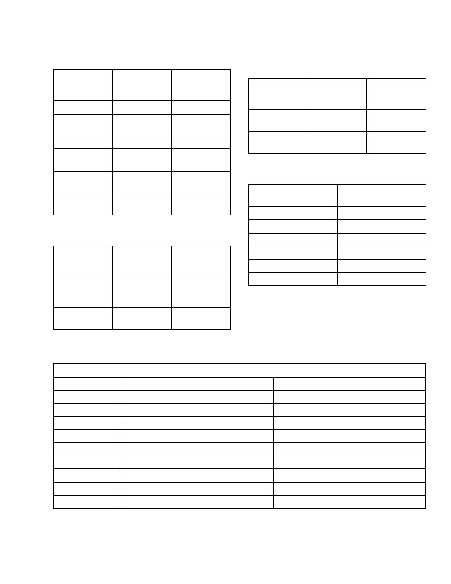
Hoses with two straps are divided into groups. The
first strap color stands for a group code, the second
strap color stands for a function code. See Table 1,
Table 2, Table 3, and Table 4 for hose identifications.
1.
SECOND STRAP
2.
FIRST STRAP
3.
IDENTIFICATION STRAP
Figure 11. Hydraulic Hoses
20
2000 SRM 1108
Torque Values
Table 1. Pilot Hoses
Hose
Function
Description
First Strap
From Hose
Fitting
Second Strap
From Hose
Fitting
Tank Line
White
Yellow
Lift A, Pilot
Line
White
Blue
Pilot Supply
White
Red
Tilt B, Pilot
Line
White
Green
Lift B, Pilot
Line
White
Orange
Tilt A, Pilot
Line
White
White
Table 2. Brake Hoses
Hose
Function
Description
First Strap
From Hose
Fitting
Second Strap
From Hose
Fitting
Regulated
Pressure From
Brake Pedal
Red
Orange
Pressure
Supply Brakes
Red
Red
Table 3. Auxiliary Hoses With Alternating
P and T
Hose
Function
Description
First Strap
From Hose
Fitting
Second Strap
From Hose
Fitting
Auxiliary A
Line
Green
Green
Auxiliary B
Line
Green
Yellow
Table 4. Steer Hoses
Hose Function
Description
Identification Strap
Tank Line
Yellow
Steer Right
Blue
Pressure Supply
Red
Auxiliary Hoses
Green
Load Sense Line
Orange
Steer Left
White
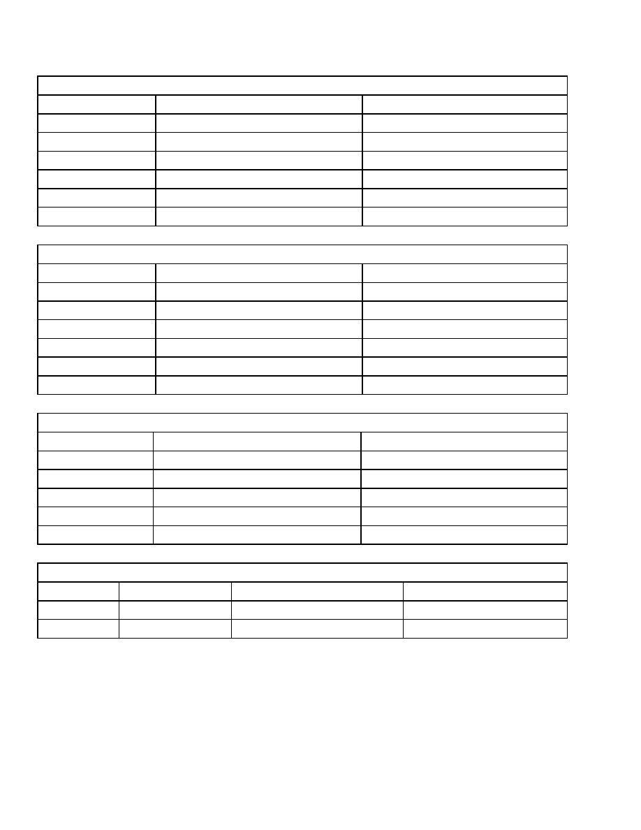
Torque Values
Valve/Cartridge Torque Specifications
Cartridge Size
210 bar (3046 psi)
345 bar (5004 psi)
#04
7 N•m (5 lbf ft)
9 N•m (7 lbf ft)
#06
14 N•m (10 lbf ft)
16 N•m (12 lbf ft)
#07
20 N•m (15 lbf ft)
31 N•m (23 lbf ft)
#08
20 N•m (15 lbf ft)
31 N•m (23 lbf ft)
#09
20 N•m (15 lbf ft)
31 N•m (23 lbf ft)
#10
22 N•m (16 lbf ft)
65 N•m (48 lbf ft)
#12
28 N•m (21 lbf ft)
76 N•m (56 lbf ft)
#16
54 N•m (40 lbf ft)
99 N•m (73 lbf ft)
#20
113 N•m (83 lbf ft)
133 N•m (98 lbf ft)
21
Torque Values
2000 SRM 1108
Nonadjustable Adapter Assembly Torques
Size
Port Thread
Assembly Torque
#04
7/16" - 20UNF-2A
20 to 22 N•m (15 to 16 lbf ft)
#06
9/16" - 18UNF-2A
45 to 50 N•m (33 to 37 lbf ft)
#08
3/4" - 16UNF-2A
80 to 88 N•m (59 to 65 lbf ft)
#12
1 1/16" - 12UNF-2A
185 to 204 N•m (136 to 150 lbf ft)
#16
1 5/16" - 12UNF-2A
270 to 297 N•m (199 to 219 lbf ft)
#20
1 5/8" - 12UNF-2A
340 to 374 N•m (251 to 276 lbf ft)
Adjustable Adapter Assembly Torques
Size
Port Thread
Assembly Torque
#04
7/16" - 20UNF-2A
20 to 22 N•m (15 to 16 lbf ft)
#06
9/16" - 18UNF-2A
45 to 50 N•m (33 to 37 lbf ft)
#08
3/4" - 16UNF-2A
80 to 88 N•m (59 to 65 lbf ft)
#12
1 1/16" - 12UNF-2A
185 to 204 N•m (136 to 150 lbf ft)
#16
1 5/16" - 12UNF-2A
270 to 297 N•m (199 to 219 lbf ft)
#20
1 5/8" - 12UNF-2A
340 to 374 N•m (251 to 276 lbf ft)
Swivel Fitting Assembly Torques
Size
Port Thread
Assembly Torque
#6
11/16" - 18UNF-2A
24 to 27 N•m (18 to 20 lbf ft)
#8
13/16" - 16UNF-2A
43 to 47 N•m (32 to 35 lbf ft)
#12
1 3/16" - 16UNF-2A
90 to 95 N•m (66 to 70 lbf ft)
#16
1 7/16" - 12UNF-2A
125 to 135 N•m (92 to 100 lbf ft)
#20
1 11/16" - 12UNF-2A
170 to 190 N•m (125 to 140 lbf ft)
Tube Side Assembly Torques
Size
Tube Diameter
Nut Thread
Assembly Torque
#6
10 mm
11/16" - 18UNF-2A
33 to 36 N•m (24 to 27 lbf ft)
#12
20 mm
13/16" - 16UNF-2A
115 to 127 N•m (85 to 94 lbf ft)
22
2000 SRM 1108
Troubleshooting
Measurements and Adjustments
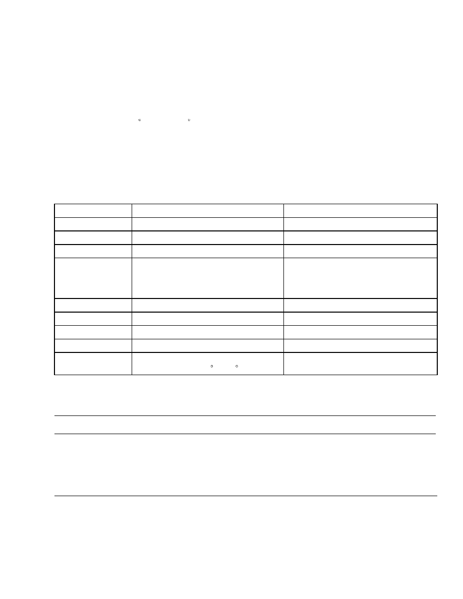
MEASUREMENTS
• Always check service manual before checking or
adjusting pressures. See Table 5.
• Always check pressures at working temperature of
hydraulic oil. 60 to 80 C (140 to 176 F).
• Always check pressures at required engine speed.
ADJUSTMENTS
Normally, replacement valves are delivered with cor-
rect pressure preset. Should adjustment be required,
observe the following:
• To raise pressure, turn adjustment screw/knob
clockwise.
• To lower pressure, turn adjustment screw/knob
counterclockwise.
• When lowering pressure, first lower pressure to be-
low required value and then increase pressure to
required level.
Table 5. Pressure Settings at 2100 RPM
Port
Description
Valve Setting
M1
Steer relief pressure
16.7 to 18.2 MPa (2425 to 2640 psi)
M2
Lift relief pressure
23 to 24.5 MPa (3335 to 3555 psi)
M3
Tilt relief pressure
23 to 24.5 MPa (3335 to 3555 psi)
MACC
Accumulator charge pressure
Upper limit: 20 to 21.5 MPa (2900
to 3120 psi)
Lower limit: 16 to 17.5 MPa (2320
to 2540 psi)
MP
Auxiliary/Lift relief pressure
23 to 24.5 MPa (3335 to 3555 psi)
MPLT
Pilot pressure
4.5 to 5 MPa (655 to 725 psi)
MSB1
Service break pressure
16.5 to 17 MPa (2395 to 2465 psi)
MSB4
Service break treadle pressure
Maximum: 16 MPa (2320 psi)
M RF
M RF - Pressure at 2100 rpm fully lowered
speed and oil temp 60 C (140 F) or higher.
Maximum 250 kPa (36 psi)
Troubleshooting
PROBLEM
POSSIBLE CAUSE
PROCEDURE OR ACTION
Oil leaks at the end caps of
the spools.
End cap seals have defects.
Replace seals.
Spool has a defect.
Replace defective spool.
Valve body has a defect.
Replace control valve section.
23

Troubleshooting
2000 SRM 1108
PROBLEM
POSSIBLE CAUSE
PROCEDURE OR ACTION
Spool will not move.
No pilot pressure.
Check and repair pilot valve and/or
priority valve, if necessary.
Dirt between spool and bore.
Clean valve as necessary.
Spool is bent or damaged.
Replace defective spool.
No electrical signal (auxiliary sec-
tion only).
Check electrical system and repair.
Spool will not return to
NEUTRAL.
Return spring is damaged.
Replace damaged spring.
Dirt between spool and bore.
Clean valve as necessary.
Spool is bent or damaged.
Replace defective spool.
Cylinders move slowly or do
not move.
Pilot pressure to low.
1.
Check levers or joystick, replace
as necessary.
2.
Check charger settings, reset if
necessary.
3.
Check pressure reducer setting,
reset if necessary.
Pressure relief valve has a defect.
Repair or adjust relief valve.
Large leaks between spool and bore.
Replace control valve section.
Hydraulic pump has a defect.
Repair or replace hydraulic pump.
Air is in pilot system.
Remove air from hydraulic system.
Restriction in hydraulic lines.
Repair or replace hydraulic lines.
Load is greater than capacity.
Handle only correct load.
Cylinder seal has defects.
Repair or replace cylinder.
Hydraulic pressure is high.
Pressure relief valve has a defect.
Repair or replace relief valve.
Pressure relief valve is not adjusted
correctly.
Adjust relief valve.
Restriction in return line.
Replace hydraulic line.
24

2000 SRM 1108
Diagrams, Schematics, or Arrangements
PROBLEM
POSSIBLE CAUSE
PROCEDURE OR ACTION
Tilt cylinders extend when
tilt spool is in NEUTRAL
position.
Cylinder seal has defects.
Repair cylinder.
Hydraulic lines have leaks.
Replace hydraulic lines.
Oil leaks between control valve spool
and bore, and tilt relief valve has a
defect.
Repair main control valve and relief
valve.
Pilot pressure activated.
Check remote control valve springs.
Tilt cylinders extend sud-
denly when tilt spool is
moved to BACK TILT posi-
tion.
Check valve to determine if tilt spool
has a defect, and/or tilt relief valve
has a defect.
Replace spool or relief valve if neces-
sary.
Delay occurs between com-
mand and movement.
Pilot return line is blocked.
Repair or replace hydraulic lines.
Tilt cylinders extend sud-
denly when tilt lever is
moved to FORWARD TILT
position.
Tilt relief valve has a defect.
Repair or adjust relief valve.
Lift cylinders retract when
lift lever is in NEUTRAL
position.
Cylinder seal has defects.
Repair cylinder.
Hydraulic lines have leaks.
Replace hydraulic lines.
Oil leaks between lift spool and bore.
Repair main control valve.
Pilot pressure activated.
Check remote control valve springs.
25
Diagrams, Schematics, or Arrangements
2000 SRM 1108
26
2000 SRM 1108
Diagrams, Schematics, or Arrangements
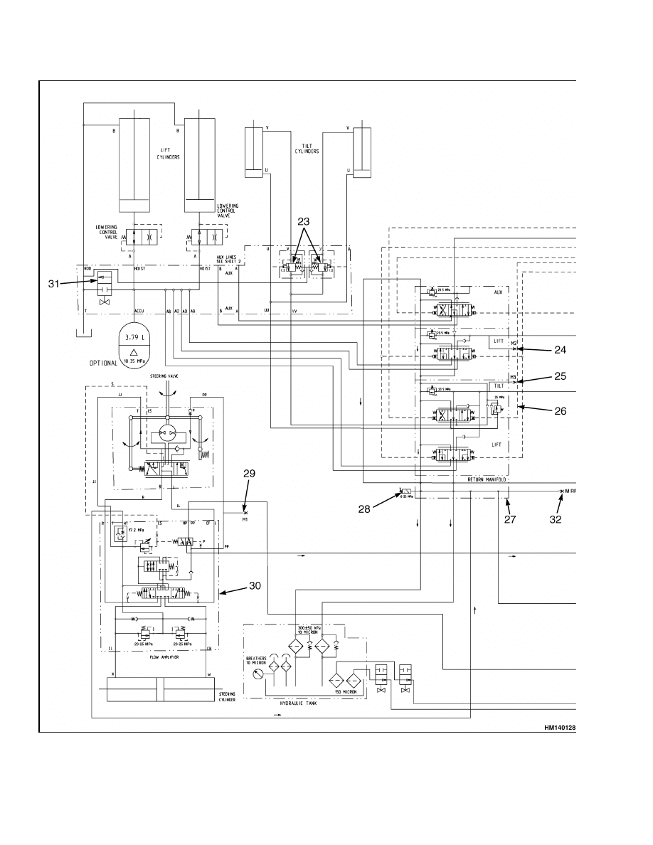
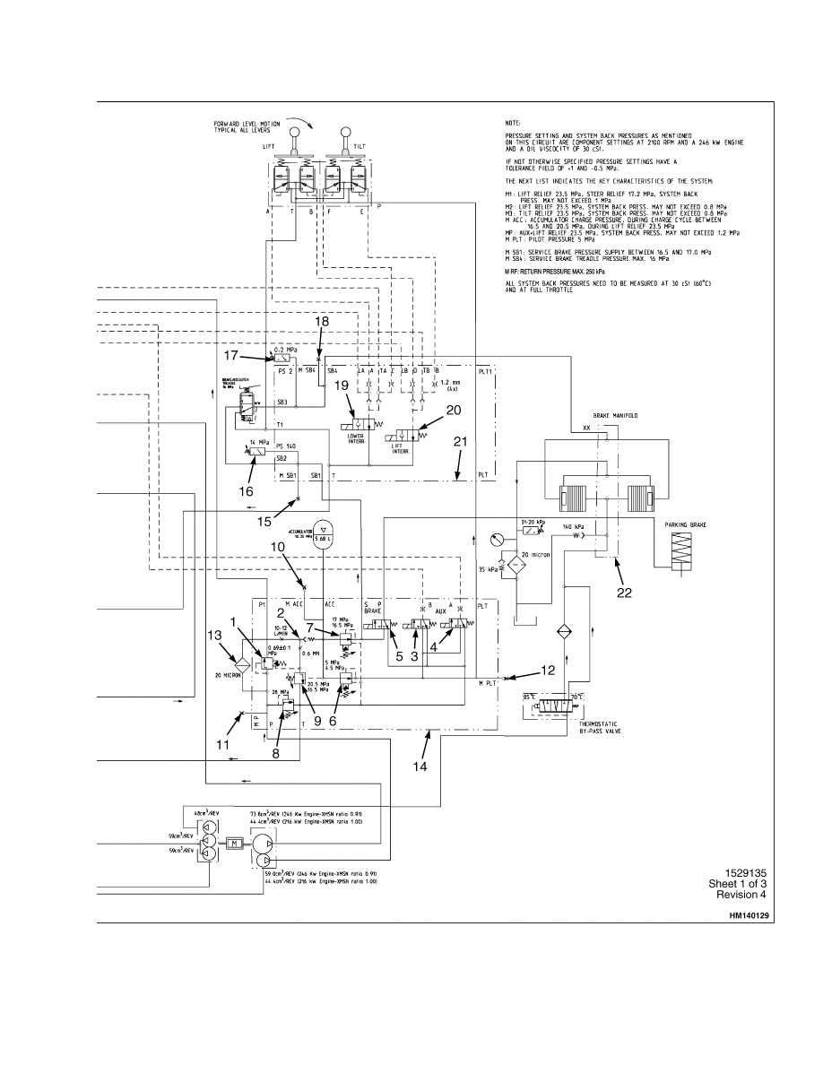
Figure 12. Hydraulic Schematic
27
Diagrams, Schematics, or Arrangements
2000 SRM 1108
Legend for Figure 12
NOTE: NUMBERS IN BOX INDICATE STAMPING ON MANIFOLD. SEE FIGURE 12.
Item
Stamping on Manifold
Description
1
1.02
6.9 Pressure Maintaining Valve
2
1.09
Check Valve
3
1.15
3-way Directional Control Valve
4
1.16
3-way Directional Control Valve
5
1.14
3-way Directional Control Valve
6
1.13
Pilot Reducing Valve
7
1.12
Brake Reducing Valve
8
1.04
Main Relief Valve
9
1.10
Charger Valve
10
MACC
Check Port MACC
11
MP
Check Port MP
12
MPLT
Check Port MPLT
13
1.03
Filter Element
14
3248-HD-421
Main Manifold
15
N/A
Check Port MSB1
16
N/A
Pressure Switch
17
N/A
Brake Pressure Switch
18
N/A
Check Port MSB4
19
N/A
Solenoid Valve
20
N/A
Solenoid Valve
21
N/A
Cab Manifold
22
N/A
Brake Manifold
23
3.05
Tilt Lock Relief Valve
24
N/A
Check Port M1
25
N/A
Check Port M2
26
N/A
Main Control Valve
27
3509-HD-424
Return Manifold
28
N/A
Pressure Switch
29
PP
Check Port M1
30
N/A
Flow Amplifier
31
3.03
Needle Valve
32
MRF
Check Port MRF
28


TECHNICAL PUBLICATIONS
2000 SRM 1108
8/04 (7/04) Printed in United Kingdom
Document Outline
- toc
- Hydraulic Plate
- Safety Precautions Maintenance and Repair
- General
- Description and Operation
- Manifold, Section 1 of Hydraulic Plate
- Main Control Valve, Section 2 of Hydraulic Plate
- Return Manifold, Section 3 of Hydraulic Plate
- Brake Manifold, Section 4 of Hydraulic Plate
- Flow Amplifier, Section 5 of Hydraulic Plate
- Hydraulic Hose Repair
- Hydraulic Hose Identification
- Torque Values
- Measurements and Adjustments
- Troubleshooting
- tables
Wyszukiwarka
Podobne podstrony:
1565183 2200SRM1110 (08 2004) UK EN
1554631 2000SRM1085 (03 2004) UK EN
910030 1400SRM0047 (08 2004) UK EN
1554632 2000SRM1086 (06 2004) UK EN
1566270 0100SRM1118 (08 2004) UK EN
910110 2200SRM0143 (08 2004) UK EN
1578950 2200SRM1119 (08 2004) UK EN
1554631 2000SRM1085 (03 2004) UK EN
1568204 0700SRM1159 (08 2005) UK EN
1566043 0620SRM1115 (08 2005) UK EN
1564283 1900SRM1107 (01 2004) UK EN
więcej podobnych podstron