PLANETARY GEAR
AXLE
H7.00-12.50H (H150-275H) [C007];
P7.00-9.00B (P150-200B) [C007];
H13.50-16.00B (H300-350B) [B019];
H360-620B [B008];
H16.00-30.00C (H360-650C) [C008];
H17.00-32.00C (H370-700C) [C008];
H700-800A [A117];
H32.00-42.00B (H700-920B) [B117];
H36.00-48.00C (H800-1050C) [C117];
H20.00-32.00F (H440-700F/FS) [E008]
PART NO. 910030
1400 SRM 47

SAFETY PRECAUTIONS
MAINTENANCE AND REPAIR
• When lifting parts or assemblies, make sure all slings, chains, or cables are correctly
fastened, and that the load being lifted is balanced. Make sure the crane, cables, and
chains have the capacity to support the weight of the load.
• Do not lift heavy parts by hand, use a lifting mechanism.
• Wear safety glasses.
• DISCONNECT THE BATTERY CONNECTOR before doing any maintenance or repair
on electric lift trucks. Disconnect the battery ground cable on internal combustion lift
trucks.
• Always use correct blocks to prevent the unit from rolling or falling. See HOW TO PUT
THE LIFT TRUCK ON BLOCKS in the Operating Manual or the Periodic Mainte-
nance section.
• Keep the unit clean and the working area clean and orderly.
• Use the correct tools for the job.
• Keep the tools clean and in good condition.
• Always use HYSTER APPROVED parts when making repairs. Replacement parts
must meet or exceed the specifications of the original equipment manufacturer.
• Make sure all nuts, bolts, snap rings, and other fastening devices are removed before
using force to remove parts.
• Always fasten a DO NOT OPERATE tag to the controls of the unit when making repairs,
or if the unit needs repairs.
• Be sure to follow the WARNING and CAUTION notes in the instructions.
• Gasoline, Liquid Petroleum Gas (LPG), Compressed Natural Gas (CNG), and Diesel fuel
are flammable. Be sure to follow the necessary safety precautions when handling these
fuels and when working on these fuel systems.
• Batteries generate flammable gas when they are being charged. Keep fire and sparks
away from the area. Make sure the area is well ventilated.
NOTE: The following symbols and words indicate safety information in this
manual:
WARNING
Indicates a condition that can cause immediate death or injury!
CAUTION
Indicates a condition that can cause property damage!

Planetary Gear Axle
Table of Contents
TABLE OF CONTENTS
General ...............................................................................................................................................................
Description .........................................................................................................................................................
Operation............................................................................................................................................................
Planetary Gear Axle Repair ..............................................................................................................................
Remove ...........................................................................................................................................................
Disassemble ...................................................................................................................................................
Planetary Axle, Disassemble ....................................................................................................................
Assemble and Install .....................................................................................................................................
Planetary Axle, Assemble .........................................................................................................................
Torque Specifications .........................................................................................................................................
Troubleshooting..................................................................................................................................................
This section is for the following models:
H7.00-12.50H (H150-275H) [C007];
P7.00-9.00B (P150-200B) [C007];
H13.50-16.00B (H300-350B) [B019];
H360-620B [B008];
H16.00-30.00C (H360-650C) [C008];
H17.00-32.00C (H370-700C) [C008];
H700-800A [A117];
H32.00-42.00B (H700-920B) [B117];
H36.00-48.00C (H800-1050C) [C117];
H20.00-32.00F (H440-700F/FS) [E008]
©2004 HYSTER COMPANY
i

"THE
QUALITY
KEEPERS"
HYSTER
APPROVED
PARTS
1400 SRM 47
Description
General
This section has a description and the repair procedures for the planetary gear axle.
Description
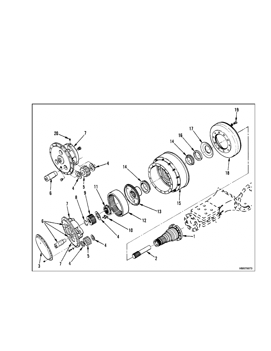
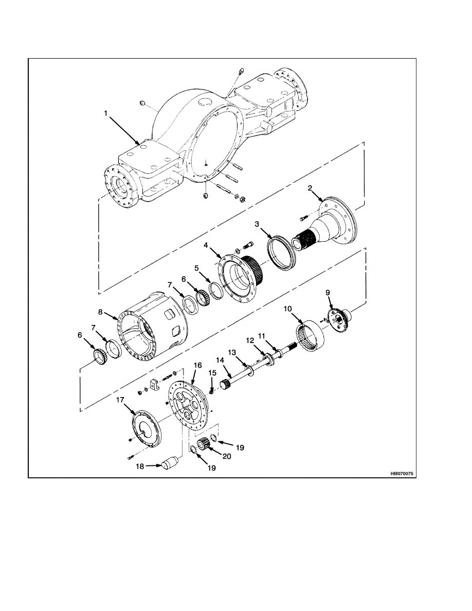
The planetary gear axle has an axle housing and
two final drive assemblies. See Figure 1 and Fig-
ure 2. Each final drive assembly is a planetary gear
unit. The planetary gear assembly changes the final
drive ratio which increases the torque to the drive
wheels. Each unit has an axle shaft, sun gear, ring
gear hub, and ring gear. There are also three plane-
tary pinions, a planetary gear carrier, and a housing.
The differential is also installed in the axle housing.
Service, parking, and auxiliary brake assemblies are
also installed on the drive axle. See the Brake sec-
tion for your unit for repair of the brakes.
1.
SPINDLE
2.
AXLE SHAFT
3.
COVER
4.
THRUST WASHER
5.
PINION
6.
PINION SHAFT
7.
PLANETARY GEAR CARRIER
8.
SNAP RING
9.
SUN GEAR
10. LOCK PLATE
11. ADJUSTMENT NUT
12. RING GEAR
13. RING GEAR HUB
14. BEARING CONE
15. HUB
16. SEAL
17. DUST SHIELD
18. BRAKE DRUM
19. CAPSCREW
20. SETSCREW
Figure 1. Planetary Axle With Drum Brakes
1
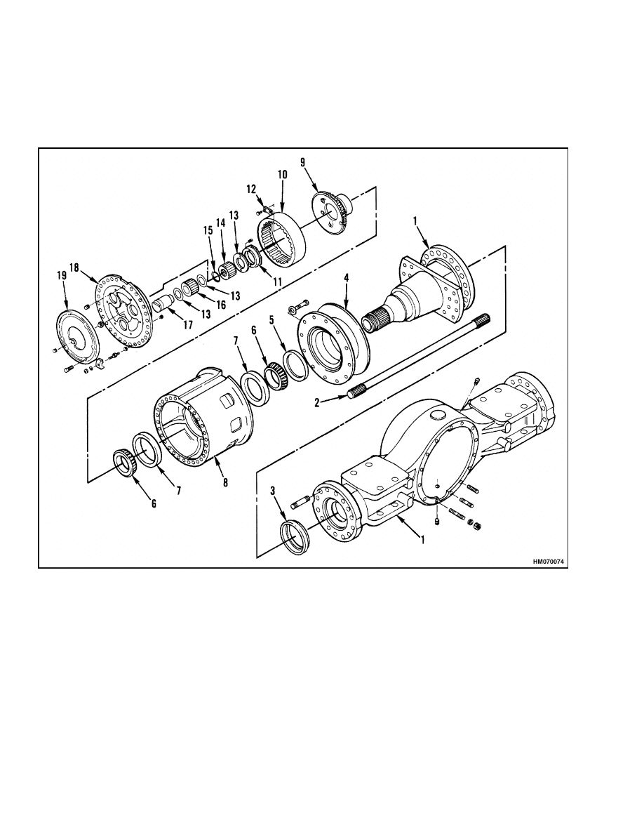
Operation
1400 SRM 47
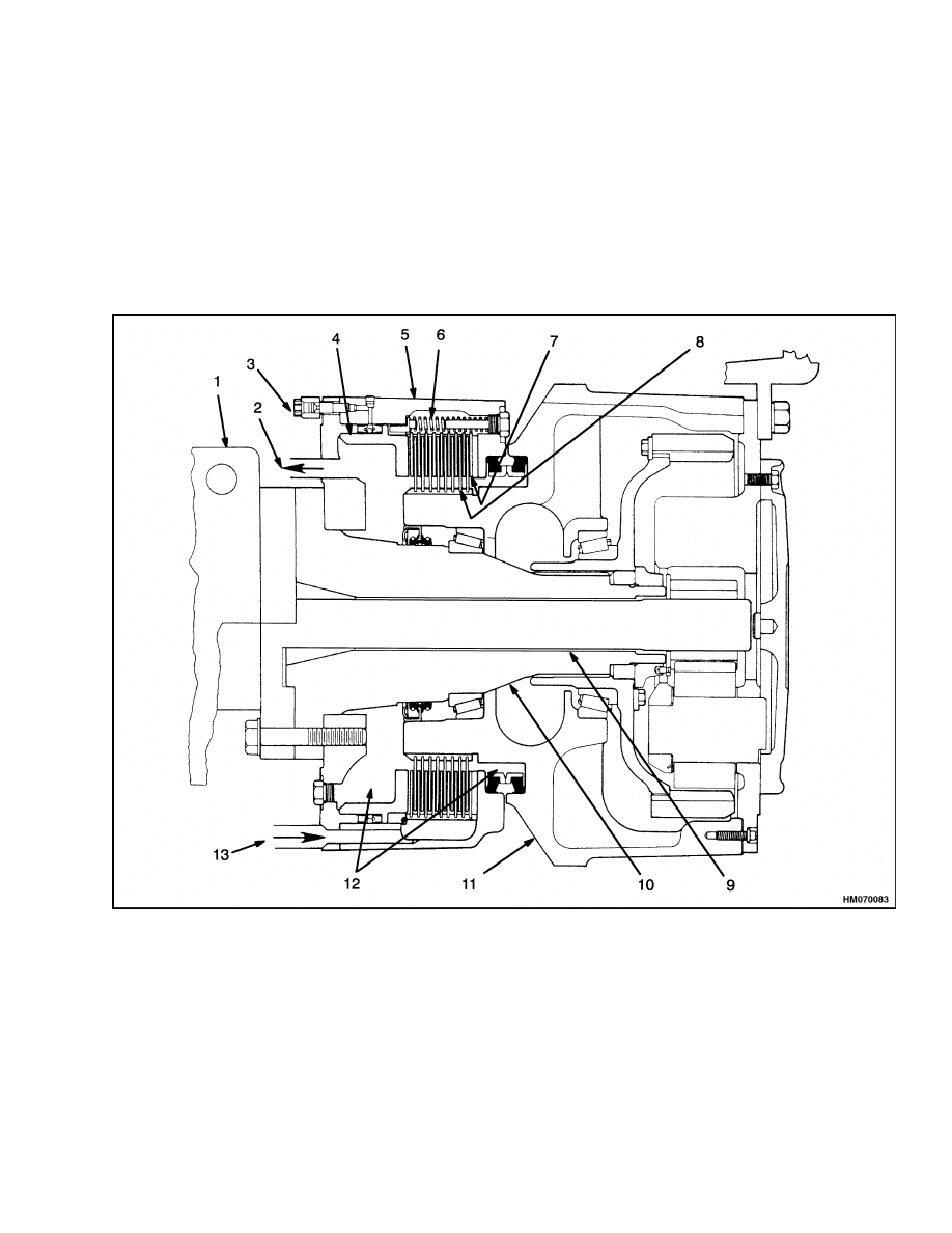
Operation
The rotation of the differential causes the axle shafts
and the sun gears to rotate. The sun gears then
cause the planetary pinions to rotate. Rotation of
the pinions causes the planetary spiders to rotate the
hubs and the drive wheels. The ring gear and the
ring gear hub do not rotate.
1.
AXLE HOUSING
2.
AXLE SHAFT
3.
SLEEVE
4.
BRAKE ROTOR
5.
OIL SEAL
6.
BEARING CONE
7.
BEARING CUP
8.
HUB
9.
RING GEAR HUB
10. RING GEAR
11. ADJUSTMENT NUT
12. LOCK PLATE
13. THRUST WASHER
14. SUN GEAR
15. SNAP RING
16. PINION (3)
17. PINION SHAFT (3)
18. PLANETARY GEAR CARRIER
19. COVER
Figure 2. Planetary Axle With Disc Brakes
2
1400 SRM 47
Planetary Gear Axle Repair
Planetary Gear Axle Repair
REMOVE
NOTE: The final drive assemblies can be removed
with the drive axle installed in the lift truck. If the
drive axle must be removed, do the following steps.
If the drive axle will not be removed, do only Step 1
and Step 2.
1.
Put blocks under lift truck frame to raise drive
wheels from ground.
2.
Drain lubricant from axle as described in the
section Periodic Maintenance for the specific
unit.
3.
On units with drum brakes, remove air chambers
as described in the section Brakes for the spe-
cific unit.
4.
If installed, remove mast assembly from lift
truck as described in the section Mast for the
specific unit.
5.
Disconnect service brake lines on models that
have hydraulic brakes. Make sure to also discon-
nect brake lines for auxiliary and parking brakes
at drive line and differential. Disconnect cooling
oil lines for units with oil-cooled brakes. Put caps
on all hydraulic lines and ports or fittings. See
Figure 3.
6.
Disconnect drive shaft at differential. On units
with disc brakes mounted to differential housing,
remove disc brake assemblies as described in the
section Brakes for the specific unit.
WARNING
Make sure the lifting device can lift 4500 kg
(10,000 lb) when moving the drive axle.
7.
Put the forks of a lift truck under axle to give
it support.
Remove bolts and nuts that hold
axle to frame. Remove drive axle from lift truck
frame. Clean all parts in solvent and dry with
compressed air.
DISASSEMBLE
1.
Remove drive wheels and tires. See Figure 1,
Figure 2, Figure 3, Figure 4, and Planetary Axle,
Disassemble.
WARNING
Completely remove the air pressure from the
tires before removing the wheels from the lift
truck. Air pressure in the tires can cause the
tire and rim parts to explode, causing serious
injury or death.
Always wear safety glasses.
2.
Remove air from tire. Remove valve core to make
sure all air is out of inner tube. Push a wire
through valve stem to make sure valve stem does
not have a restriction.
WARNING
Use a correct lifting device to handle tires
and wheels.
The tires and wheels on some
lift trucks can weigh approximately 750 kg
(1650 lb).
3.
Remove wheel nuts and clamps, then use lifting
device to remove tire and wheel from lift truck.
4.
Drain oil from end of axle housing. On units with
oil-cooled brakes, drain cooling oil from service
brakes.
5.
On units with disc brakes, remove brake calipers
as follows:
a. Remove end plates from calipers. Remove
brake pads from calipers.
b. Disconnect brake lines at calipers. Remove
capscrews that hold calipers to axle housing.
Make a note of the location of any shims that
are used at the caliper mount.
3
Planetary Gear Axle Repair
1400 SRM 47
Figure 3. Planetary Axle With Oil-Cooled Brakes
4
1400 SRM 47
Planetary Gear Axle Repair
Legend for Figure 3
1.
AXLE HOUSING
2.
SPINDLE
3.
SEAL
4.
DRIVER
5.
OIL SEAL
6.
BEARING CONE
7.
BEARING CUP
8.
HUB
9.
RING GEAR HUB
10. RING GEAR
11. INNER HUB
12. ADJUSTMENT NUT
13. LOCK PLATE AND PIN
14. AXLE
15. THRUST BUTTON
16. PLANETARY GEAR CARRIER
17. COVER
18. PINION SHAFT (3)
19. THRUST WASHER
20. PINION GEAR (3)
1.
AXLE HOUSING
2.
COOLING OIL FLOW, RETURN
3.
BRAKING HYDRAULIC LINE
4.
PISTON
5.
BRAKE HOUSING
6.
RETURN SPRING
7.
STATIONARY DISCS
8.
ROTATING DISCS
9.
AXLE SHAFT
10. SPINDLE
11. HUB
12. COOLING OIL
13. COOLING OIL FLOW, SUPPLY
Figure 4. Brake and Axle Assembly, Oil-Cooled Brake
5
Planetary Gear Axle Repair
1400 SRM 47
WARNING
Brake linings can contain dangerous fibers.
Breathing the dust from these linings is a can-
cer or lung disease hazard. Do not create dust!
Do not clean brake parts with compressed
air or by brushing.
Use vacuum equipment
approved for brake dust or follow the cleaning
procedure in this section.
When the brake
drums are removed, do not create dust.
Do not sand, grind, chisel, hammer, or change
linings in any way that will create dust. Any
changes to linings must be done in a restricted
area with special ventilation. Protective cloth-
ing and a respirator must be used.
NOTE: Normally, the disc assembly (fixed and rotat-
ing discs) of the oil-cooled brakes is replaced when
the drive axle is disassembled.
6.
Disassemble oil-cooled brake as described in the
section Oil-Cooled Brakes.
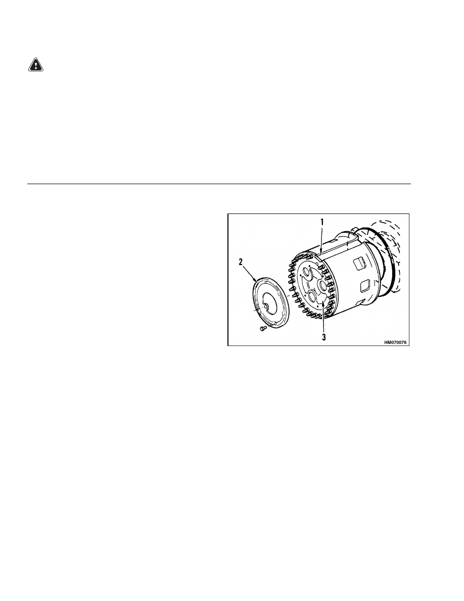
Planetary Axle, Disassemble
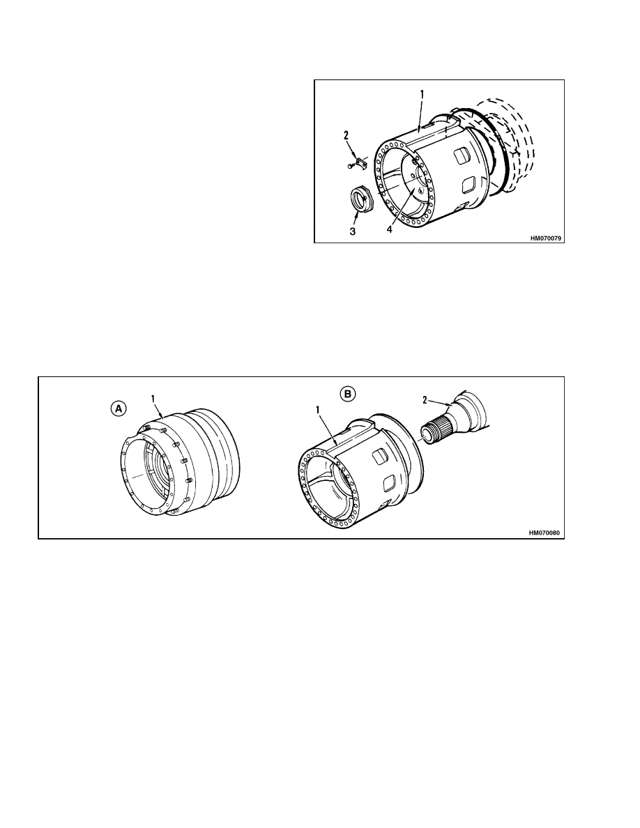
STEP 1.
Remove cover from planetary gear carrier.
NOTE: Disc brake-type axle shown. Others similar.
1.
HUB
2.
COVER
3.
PLANETARY GEAR CARRIER
6
1400 SRM 47
Planetary Gear Axle Repair
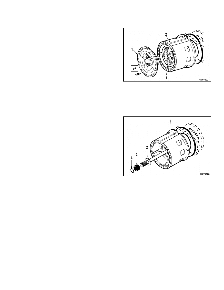
STEP 2.
Put alignment marks on planetary gear carrier and
hub. Remove planetary gear carrier capscrews. Re-
move planetary gear carrier from hub. Use a pry bar
or put capscrews in puller holes in planetary gear car-
rier. Remove ring gear from ring gear hub.
NOTE: Disc brake-type axle shown. Others similar.
1.
PLANETARY GEAR CARRIER
2.
HUB
3.
RING GEAR
NOTE: Sun gear is part of the axle on axles with oil-cooled brakes. There is no thrust washer or snap ring.
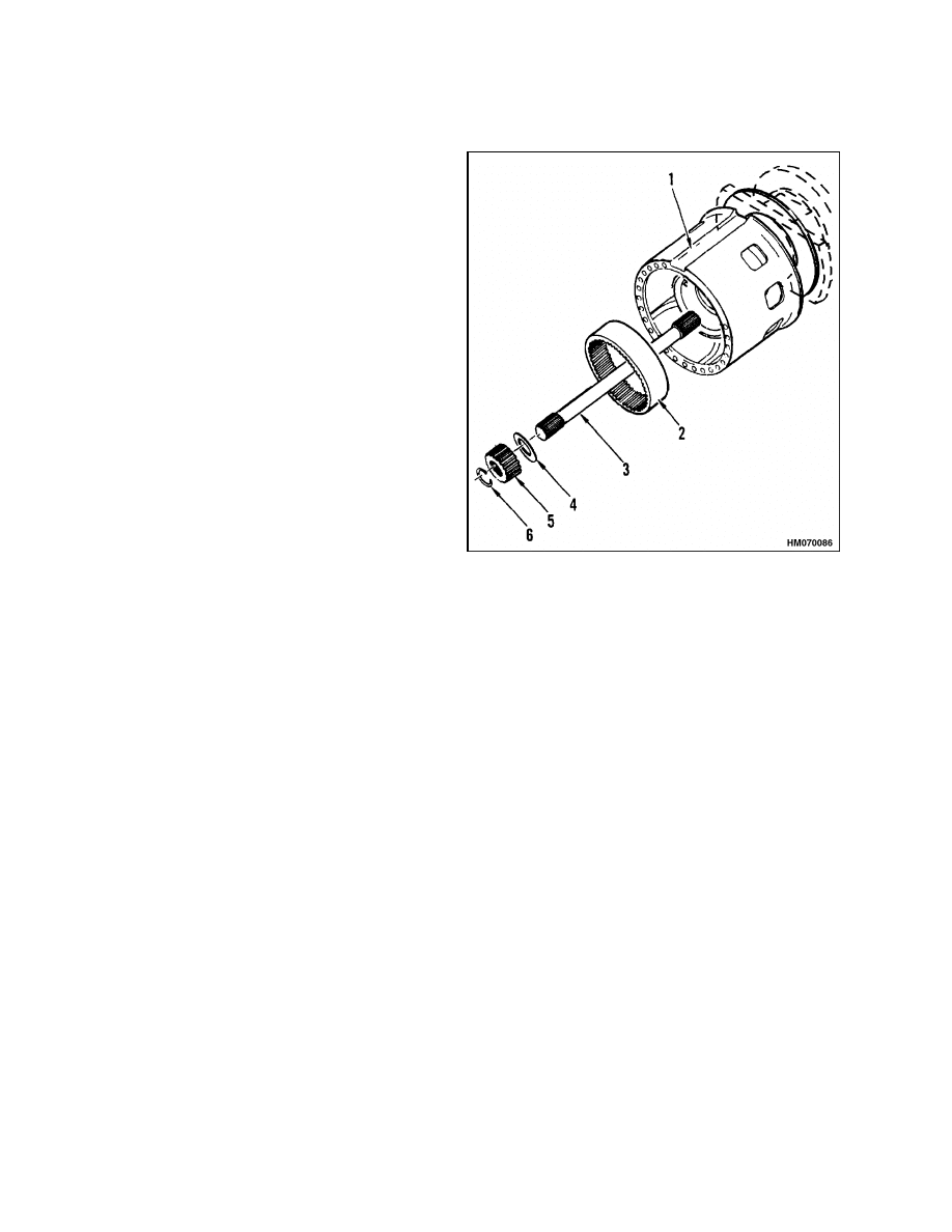
STEP 3.
Remove axle shaft, sun gear, and thrust washer from
housing. If the sun gear is separate, remove it from
axle shaft.
NOTE: Disc brake-type axle shown. Others similar.
1.
HUB
2.
THRUST WASHER
3.
SUN GEAR
4.
SNAP RING
7
Planetary Gear Axle Repair
1400 SRM 47
STEP 4.
Remove lock plate for adjustment nut. Remove ad-
justment nut. Connect a lifting device to hub for sup-
port. Use a puller to remove ring gear hub.
NOTE: Disc brake-type axle shown. Others similar.
1.
HUB
2.
LOCK PLATE
3.
ADJUSTMENT NUT
4.
RING GEAR HUB
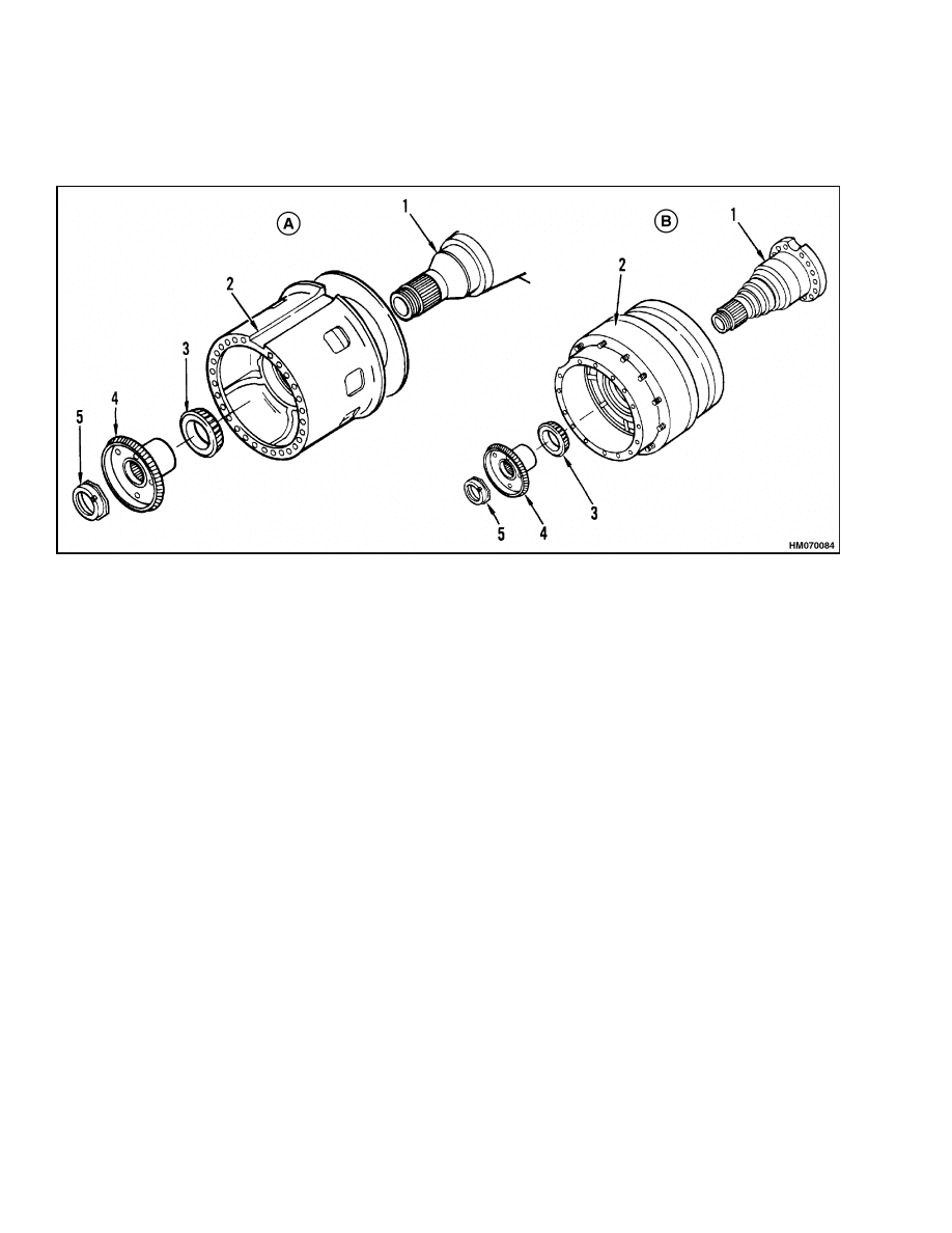
STEP 5.
Attach a lifting device to hub. Carefully remove hub from spindle. Driver splines of hub engage brake discs of
oil-cooled brake. See Figure 4.
A. DRUM BRAKE-TYPE AXLE SHOWN. OTHERS
SIMILAR.
B. DISC BRAKE-TYPE AXLE SHOWN. OTHERS
SIMILAR.
1.
HUB
2.
SPINDLE
8
1400 SRM 47
Planetary Gear Axle Repair
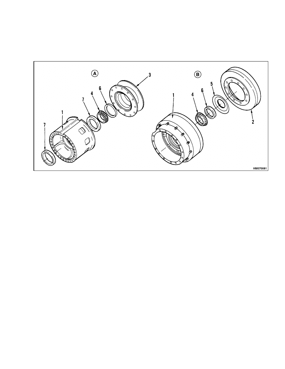
STEP 6.
Remove brake drum or brake rotor and bearings from hub of drum or disc brake axle as necessary. Remove
driver from hub and brake housing, brake discs, piston assembly, and bearings from axle of oil-cooled brake as
necessary. See Figure 4.
A. DISC BRAKE-TYPE AXLE SHOWN. OTHERS
SIMILAR.
B. DRUM BRAKE-TYPE AXLE SHOWN. OTHERS
SIMILAR.
1.
HUB
2.
BRAKE DRUM
3.
BRAKE ROTOR
4.
BEARING CONE
5.
DUST SEAL
6.
OIL SEAL
7.
BEARING CUP
9
Planetary Gear Axle Repair
1400 SRM 47
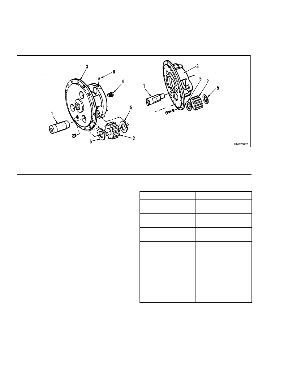
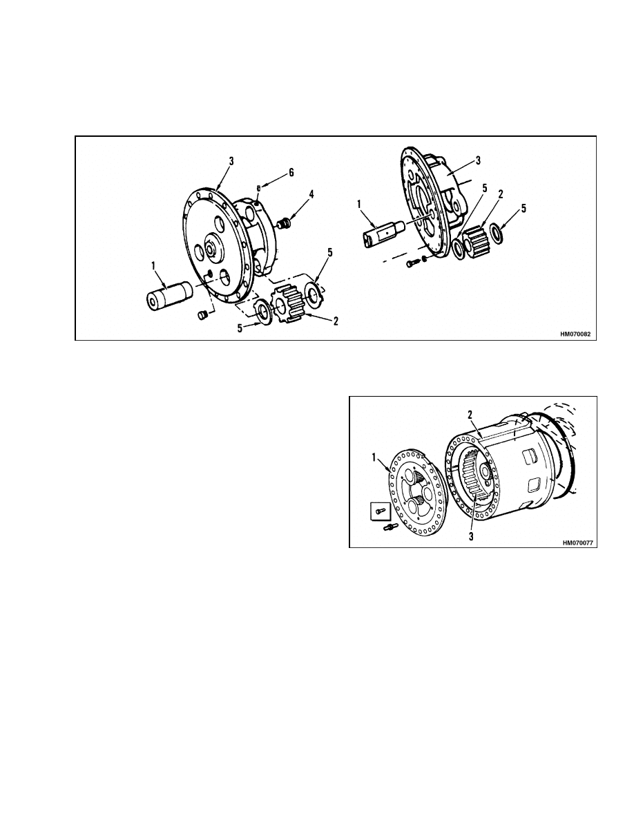
STEP 7.
Disassemble planetary gear carrier assembly as necessary. If setscrews are used to hold the pinions in position,
put alignment marks on planetary gear carrier and pinion. Use a press to remove pinions.
1.
PINION SHAFT
2.
PINION
3.
PLANETARY GEAR CARRIER
4.
THRUST BUTTON
5.
THRUST WASHER
6.
SETSCREW
ASSEMBLE AND INSTALL
NOTE: Normally, the disc assembly (fixed and rotat-
ing discs) of the oil-cooled brakes is replaced when
the drive axle is disassembled.
1.
Replace disc assembly and assemble oil-cooled
brake as described in the section Oil-Cooled
Brakes. See Figure 1, Figure 2, Figure 3, Fig-
ure 4, and Planetary Axle, Assemble.
NOTE: During assembly and installation, see Table 2
for torque specifications. Lubricate all parts with
clean axle lubricant.
2.
If the axle housing was removed, install it as de-
scribed in Step 3 to Step 7. Assemble planetary
gear carrier assemblies. See Planetary Axle, Dis-
assemble.
3.
Use a jack or the forks of a lift truck to put
axle under frame. Install nuts and bolts. In-
stall plates on H7.00-12.50H (H150-275H),
P7.00-9.00B (P150-200B), and H13.50-16.00B
(H300-350B) models. Tighten nuts as shown in
Table 1.
Table 1. Axle-to-Frame Fasteners
Model
Torque
H7.00-12.50H
(H150-275H)
410 N•m (300 lbf ft)
P7.00-9.00B
(P150-200B)
410 N•m (300 lbf ft)
H13.50-16.00B
(H300-350B)
650 N•m (480 lbf ft)
H360-620B,
H16.00-32.00C
(H360-700C)
H20.00-32.00F
(H440-700F/FS)
1625 to 2035 N•m
(1200 to 1500 lbf ft)
H7.00-800A,
H32.00-42.00B
(H700-920B),
H36.00-48.00C
(H800-1050C),
1625 to 2035 N•m
(1200 to 1500 lbf ft)
10
1400 SRM 47
Planetary Gear Axle Repair
4.
Install service, auxiliary, and parking brake com-
ponents as described in the section Brakes for
the specific unit.
5.
Connect drive shaft to differential or to transfer
case.
6.
Connect brake lines. On units with oil-cooled
brakes, also connect hydraulic lines for cooling
oil of service brakes.
7.
Install wheels. Tighten nuts according to speci-
fications in Table 3.
8.
Fill axle with lubricant as specified in the section
Periodic Maintenance for the specific unit.
Planetary Axle, Assemble
STEP 1.
Install new disc set, spacer, piston, and seals in brake housing for oil-cooled brake as described in the section
Oil-Cooled Brakes. Install housing assembly on cover. Install bearings and dust shield in hub. Install driver,
brake drum, or brake rotor on hub. Tighten capscrews according to specifications in Table 2.
NOTE: Assembly of axle for oil-cooled brake similar.
A. DISC BRAKE-TYPE ASSEMBLY SHOWN.
B. DRUM BRAKE-TYPE ASSEMBLY SHOWN.
1.
HUB
2.
BRAKE DRUM
3.
BRAKE ROTOR
4.
BEARING CONE
5.
DUST SEAL
6.
OIL SEAL
7.
BEARING CUP
11
Planetary Gear Axle Repair
1400 SRM 47
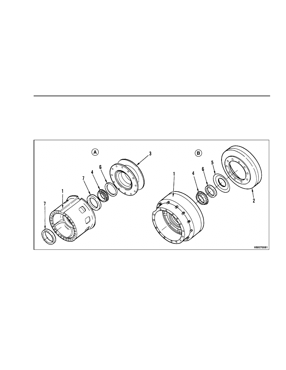
STEP 2.
Attach a lifting device to hub and install it on spindle. Install outer bearing cone and ring gear hub. Install
adjustment nut.
NOTE: Assembly of axle for oil-cooled brake similar.
A. DISC BRAKE-TYPE ASSEMBLY SHOWN.
B. DRUM BRAKE-TYPE ASSEMBLY SHOWN.
1.
SPINDLE
2.
HUB
3.
BEARING CONE
4.
RING GEAR HUB
5.
ADJUSTMENT NUT
12
1400 SRM 47
Planetary Gear Axle Repair
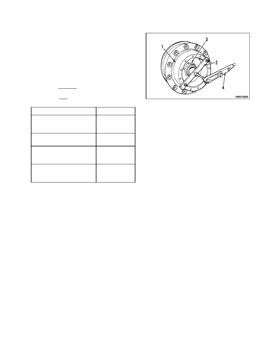
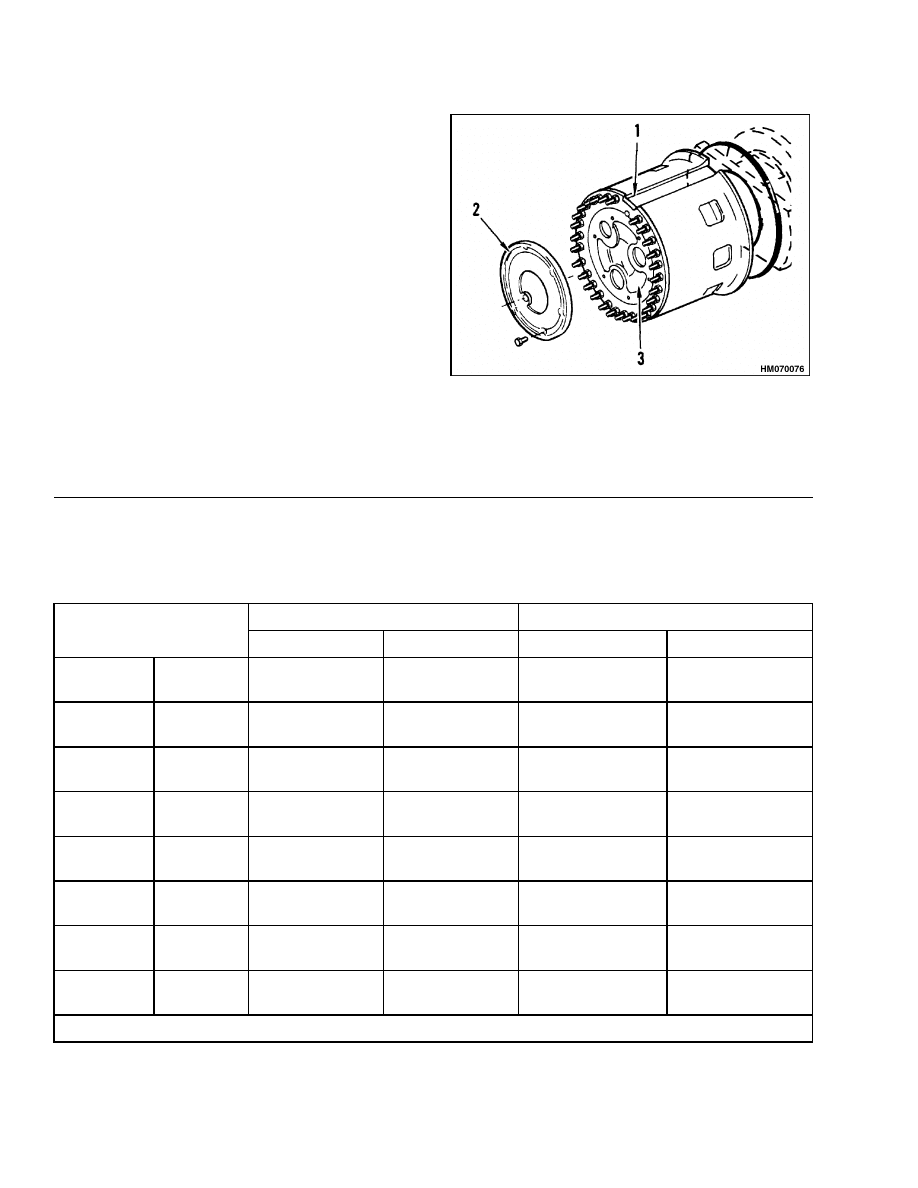
STEP 3.
Tighten adjustment nut to 540 N•m (400 lbf ft)
while rotating hub. Loosen nut and tighten it again
to 540 N•m (400 lbf ft).
Loosen adjustment nut
until it just touches ring gear hub.
Install a bar
and nut on hub as shown. Use a torque wrench to
check rotating torque of hub.
This is the initial
value.
Make sure hub is rotating while checking
the torque. Tighten adjustment nut while checking
rotating torque again. Tighten adjustment nut so
torque value increases by the amount shown in the
following table. The final torque value must be the
initial value plus the value shown in the following
table.
Model
N•m (lbf ft)
H7.00-12.50H (H150-275H)
P7.00-9.00B (P150-200B)
H13.50-16.00B (H300-350B)
7 to 12 N•m
(5 to 9 lbf ft)
H360-460B, H16.00-23.00C
(H360-510C)
11 to 16 N•m
(8 to 12 lbf ft)
H520-620B, H25.00-32.00C
(H520-700C), H20.00-32.00F
(H440-700F/FS)
14 to 19 N•m
(10 to 14 lbf ft)
H700-800A
H32.00-42.00B (H700-920B)
H36.00-48.00C (H800-1050C)
19 to 24 N•m
(14 to 18 lbf ft)
NOTE: Drum brake-type axle shown. Others similar.
1.
HUB
2.
BAR
3.
ADJUSTMENT NUT
4.
TORQUE WRENCH
13
Planetary Gear Axle Repair
1400 SRM 47
NOTE: Sun gear is part of the axle on axles with oil-cooled brakes. There is no thrust washer or snap ring.
STEP 4.
Install ring gear, axle shaft, thrust washer, sun gear,
and snap ring.
NOTE: Disc brake-type axle shown. Others similar.
1.
HUB
2.
RING GEAR
3.
AXLE SHAFT
4.
THRUST WASHER
5.
SUN GEAR
6.
SNAP RING
14
1400 SRM 47
Planetary Gear Axle Repair
STEP 5.
Assemble planetary gear carrier assembly. If the pinions have a flat side, the flat side must be toward the
outside of the hub circle. When installing the pinions, be sure to align the alignment marks. Use a press to
install pinions. After the pinions are installed, install setscrews.
1.
PINION SHAFT
2.
PINION
3.
PLANETARY GEAR CARRIER
4.
THRUST BUTTON
5.
THRUST WASHER
6.
SETSCREW
STEP 6.
Use a silicone gasket material between hub and plan-
etary gear carrier assembly. Connect a lifting device
to planetary gear carrier assembly and install it on
hub. Align the marks between hub and planetary
gear carrier assembly during installation. Tighten
nuts or capscrews as specified in Table 2.
NOTE: Disc brake-type axle shown. Others similar.
1.
PLANETARY GEAR CARRIER
2.
HUB
3.
RING GEAR
15
Torque Specifications
1400 SRM 47
STEP 7.
Use a silicone gasket material between cover and
planetary gear carrier. Align the marks and install
cover. Tighten capscrews as specified in Table 2.
NOTE: Disc brake-type axle shown. Others similar.
1.
HUB
2.
COVER
3.
PLANETARY GEAR CARRIER
Torque Specifications
Table 2. Standard Torque Values for Axle Fasteners
Lock Nuts
Capscrews and Nuts
Size
N•m
lbf ft
N•m
lbf ft
1/4-20
1/4-28
UNC
UNF
12 to 15
13 to 18
9 to 11
10 to 13
13 to 18
13 to 18
10 to 13
10 to 13
5/16-18
5/16-24
UNC
UNF
24 to 33
27 to 40
18 to 24
20 to 30
27 to 40
27 to 40
20 to 30
20 to 30
3/8-16
3/8-24
UNC
UNF
40 to 54
48 to 68
30 to 40
35 to 50
48 to 68
48 to 68
35 to 50
40 to 50
7/16-14
7/16-20
UNC
UNF
68 to 88
81 to 102
50 to 65
60 to 75
81 to 102
88 to 115
60 to 75
65 to 85
9/16-12
9/16-18
UNC
UNF
102 to 135
115 to 155
75 to 100
85 to 115
115 to 155
135 to 175
85 to 115
100 to 130
5/8-11
5/8-18
UNC
UNF
150 to 195
175 to 225
110 to 145
130 to 165
175 to 225
200 to 260
130 to 165
150 to 190
5/8-11
5/8-18
UNC
UNF
200 to 260
245 to 310
150 to 190
180 to 230
245 to 310
285 to 365
180 to 230
210 to 270
3/4-10
3/4-16
UNC
UNF
265 to 475
420 to 540
200 to 350
310 to 400
420 to 540
490 to 640
310 to 400
360 to 470
NOTE: Torque values are for parts lubricated with a lightweight oil.
16
1400 SRM 47
Torque Specifications
Table 2. Standard Torque Values for Axle Fasteners (Continued)
Lock Nuts
Capscrews and Nuts
Size
N•m
lbf ft
N•m
lbf ft
7/8-9
7/8-14
UNC
UNF
595 to 785
680 to 880
440 to 580
500 to 650
680 to 860
780 to 1015
500 to 630
575 to 750
1.0-8
1.0-12
1.0-14
UNC
UNF
UN
880 to 1185
985 to 1290
985 to 1290
650 to 875
725 to 950
725 to 950
1050 to 1355
1150 to 1490
1150 to 1490
775 to 1000
850 to 1100
850 to 1100
NOTE: Torque values are for parts lubricated with a lightweight oil.
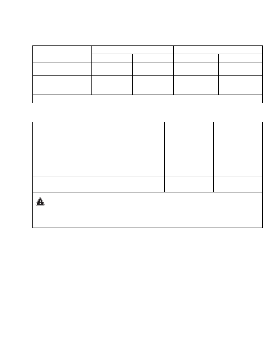
Table 3. Drive Wheel Nut Torque
Model
N•m
lbf ft
H7.00-12.50H (H150-275H), P7.00-9.00B (P150-200B),
H13.50-16.00B (H300-350B)
Clamp Nuts
305 to 375
225 to 275
Disc Clamp Nuts
610 to 675
450 to 500
H360-620B, H16.00-32.00C (H360-700C)
270 to 340
200 to 250
H700-800A, H32.00-42.00B (H700-920B)
190 to 240
140 to 180
H36.00-48.00C (H800-1050C)
305 to 340
225 to 250
H20.00-32.00F (H440-700F/FS)
405 to 440
300 to 325
WARNING
Do not use any lubricant on the studs or nuts. When the wheels have been installed, check all
wheel nuts after 4 to 8 hours of operation.
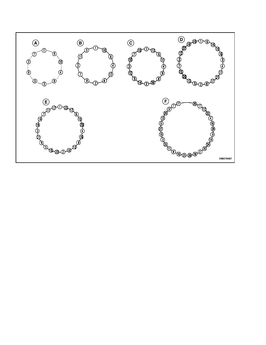
NOTE: See Figure 5 for wheel nut tightening sequence.
17
Torque Specifications
1400 SRM 47
NOTE: SEE TABLE 3 FOR CORRECT TORQUE VALUES.
A. H13.50-16.00B (H300-350B)
B. H360-460B, H7.00-12.50H (H150-275H), P7.00-9.00B (P150-200B)
C. H520-620B, H25.00-30.00C (H550-650C)
D. H16.00-23.00C (H360-510C)
E. H700-800A, EARLY MODEL H32.00-42.00B (H700-920B)
F.
LATE MODEL H32.00-42.00B (H700-920B), H36.00-48.00C (H800-1050C), H20.00-32.00F (H440-700F/FS)
Figure 5. Wheel Nut Tightening Sequence
18

1400 SRM 47
Troubleshooting
Troubleshooting
PROBLEM
POSSIBLE CAUSE
PROCEDURE OR ACTION
The lift truck will not move.
The axle shaft is broken.
Replace axle shaft.
The gears in the final drive are dam-
aged.
Replace gears.
The final drive makes noise.
The gears or shafts in the final drive
are damaged.
Replace gears.
There is no oil in the axle.
Fill axle with oil.
The final drive has leaks.
There is no sealant between the
joints of the planetary assembly.
Replace sealant.
There are capscrews missing from
the cover of the planetary assembly.
Replace missing capscrews.
There are plugs missing from the
cover or housing of the planetary
axle.
Replace missing plugs.
Oil seals are worn or damaged.
Replace oil seals.
Fittings or oil lines are loose or dam-
aged (units with oil-cooled brakes
only).
Tighten fittings or oil lines.
19

NOTES
____________________________________________________________
____________________________________________________________
____________________________________________________________
____________________________________________________________
____________________________________________________________
____________________________________________________________
____________________________________________________________
____________________________________________________________
____________________________________________________________
____________________________________________________________
____________________________________________________________
____________________________________________________________
____________________________________________________________
____________________________________________________________
____________________________________________________________
____________________________________________________________
____________________________________________________________
____________________________________________________________
____________________________________________________________
____________________________________________________________
20


TECHNICAL PUBLICATIONS
1400 SRM 47
8/04 (11/03)(1/00)(7/97)(2/97)(10/88)(8/84)(5/80)(2/79) Printed in United Kingdom
Document Outline
Wyszukiwarka
Podobne podstrony:
897480 1400SRM0499 (10 2004) UK EN
897067 1400SRM0285 (05 2004) UK EN
1566270 0100SRM1118 (08 2004) UK EN
910110 2200SRM0143 (08 2004) UK EN
1574068 1400SRM1171 (08 2005) UK EN
1578950 2200SRM1119 (08 2004) UK EN
1565181 2000SRM1108 (08 2004) UK EN
1565183 2200SRM1110 (08 2004) UK EN
897880 1400SRM0618 (06 2004) UK EN
897480 1400SRM0499 (10 2004) UK EN
więcej podobnych podstron