OPERATOR’S CAB
RS45-27CH, RS45-30CH, RS45-27IH, RS46-33CH,
RS46-30IH, RS46-36CH, RS46-33IH First Used
on 1563, 1566, 1567, 1568, 1570, and Up [A222]
PART NO. 1586982
100 SRM 1177

SAFETY PRECAUTIONS
MAINTENANCE AND REPAIR
• When lifting parts or assemblies, make sure all slings, chains, or cables are correctly
fastened, and that the load being lifted is balanced. Make sure the crane, cables, and
chains have the capacity to support the weight of the load.
• Do not lift heavy parts by hand, use a lifting mechanism.
• Wear safety glasses.
• DISCONNECT THE BATTERY CONNECTOR before doing any maintenance or repair
on electric lift trucks. Disconnect the battery ground cable on internal combustion lift
trucks.
• Always use correct blocks to prevent the unit from rolling or falling. See HOW TO PUT
THE LIFT TRUCK ON BLOCKS in the Operating Manual or the Periodic Mainte-
nance section.
• Keep the unit clean and the working area clean and orderly.
• Use the correct tools for the job.
• Keep the tools clean and in good condition.
• Always use HYSTER APPROVED parts when making repairs. Replacement parts
must meet or exceed the specifications of the original equipment manufacturer.
• Make sure all nuts, bolts, snap rings, and other fastening devices are removed before
using force to remove parts.
• Always fasten a DO NOT OPERATE tag to the controls of the unit when making repairs,
or if the unit needs repairs.
• Be sure to follow the WARNING and CAUTION notes in the instructions.
• Gasoline, Liquid Petroleum Gas (LPG), Compressed Natural Gas (CNG), and Diesel fuel
are flammable. Be sure to follow the necessary safety precautions when handling these
fuels and when working on these fuel systems.
• Batteries generate flammable gas when they are being charged. Keep fire and sparks
away from the area. Make sure the area is well ventilated.
NOTE: The following symbols and words indicate safety information in this
manual:
WARNING
Indicates a condition that can cause immediate death or injury!
CAUTION
Indicates a condition that can cause property damage!

Operator’s Cab
Table of Contents
TABLE OF CONTENTS
General ...............................................................................................................................................................
Cab Repair..........................................................................................................................................................
Remove ...........................................................................................................................................................
Install .............................................................................................................................................................
Seat Assembly Removal.....................................................................................................................................
Armrest...............................................................................................................................................................
Adjust .............................................................................................................................................................
Steering Column Repair ....................................................................................................................................
Remove ...........................................................................................................................................................
Disassemble and Assemble ...........................................................................................................................
Install .............................................................................................................................................................
Window Wipers Replacement ............................................................................................................................
Window Wiper Assembly...............................................................................................................................
Replace .......................................................................................................................................................
Front, Rear, and Top Window Wiper Motor Assembly.................................................................................
Replace .......................................................................................................................................................
Window Washer Motors and Pumps .................................................................................................................
Repair .............................................................................................................................................................
Window Replacement.........................................................................................................................................
Front Window, Replace..................................................................................................................................
Rear Window, Replace ...................................................................................................................................
Top Window, Replace .....................................................................................................................................
Side Window, Replace ....................................................................................................................................
Door Window, Replace ...................................................................................................................................
Bottom Window .........................................................................................................................................
Sliding Window..........................................................................................................................................
Door Handle Assembly ......................................................................................................................................
Remove ...........................................................................................................................................................
Install .............................................................................................................................................................
Heater Assembly ................................................................................................................................................
Remove ...........................................................................................................................................................
Install .............................................................................................................................................................
Heater Control Knob .....................................................................................................................................
Switches .....................................................................................................................................................
Cable ..........................................................................................................................................................
Adjust.....................................................................................................................................................
Heater Components .......................................................................................................................................
Replace .......................................................................................................................................................
Instruments, Switches, and Controls ...............................................................................................................
Label Replacement.............................................................................................................................................
This section is for the following models:
RS45-27CH, RS45-30CH, RS45-27IH, RS46-33CH, RS46-30IH, RS46-36CH,
RS46-33IH First Used on 1563, 1566, 1567, 1568, 1570, and Up [A222]
©2005 HYSTER COMPANY
i

"THE
QUALITY
KEEPERS"
HYSTER
APPROVED
PARTS

100 SRM 1177
Cab Repair
General
A fully enclosed operator’s cab is positioned on four
large rubber anti-vibration mounts to isolate the
operator from shocks, noise, and vibration.
The
operator’s compartment includes electronic controls
for hydraulic systems, 3B6 load limiter system,
steering wheel, instrument panel, transmission,
brake system controls, and operator’s seat. The cab
is installed on a platform and support base above
the main frame. Stairways and walkways on both
sides of the ReachStacker
®
give access to the cab. To
gain access to the major parts under the cab floor,
remove the two hood panels under the cab and the
hood panel in front of the cab. For major repairs to
the cab, the cab can be completely removed from the
frame of the ReachStacker.
Cab Repair
REMOVE
NOTE: The operator’s cab may be removed from ei-
ther side of the ReachStacker
®
.
1.
Switch OFF the engine.
2.
Disconnect battery ground lead.
3.
Remove the handrail from the walkway.
4.
Remove the two hood panels under the operator’s
cab.
5.
Remove the hood panel in front of the operator’s
cab.
6.
Disconnect the hex bolts holding steering pump.
7.
Remove the bolts holding brake valve.
8.
Disconnect electrical cable.
9.
Disconnect electrical harnesses that are located
at rear side of heater unit.
10. Disconnect ground lead.
WARNING
Before removing heater hoses, allow time for
heater hoses to cool down.
Hot water may
cause severe burns.
11. Disconnect the hoses at the heater.
12. Install a lifting eye bolt on each side of the oper-
ator’s cab roof.
WARNING
Verify the lifting device has a minimum capac-
ity to lift 758 kg (1671 lb). A lifting device that
does not have the minimum capacity can break
causing the cab to drop and may result in seri-
ous personal injury.
13. Connect a lifting device to the lifting eye bolts.
14. Remove four mounting bolts, two on left side and
two on right side of the truck.
CAUTION
Lift the operator’s cab carefully.
Verify all
wires and attachments are disconnected and
loose components are not obstructing the
movement.
15. Carefully lift cab away from truck. Set cab as-
sembly in a suitable storage area and put blocks
under cab to stabilize and prevent damage.
16. Remove four rubber isolator mounts from frame
and inspect for damage. Reinstall or replace if
necessary.
INSTALL
WARNING
Verify the lifting device has a minimum capac-
ity to lift 758 kg (1671 lb). A lifting device that
does not have the minimum capacity can break
causing the cab to drop and may result in seri-
ous personal injury.
1.
Connect a lifting device to the lifting eye bolts.
1
Cab Repair
100 SRM 1177
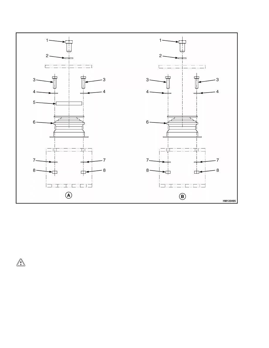
A. REAR OF CAB
B. FRONT OF CAB
1.
CAPSCREW
2.
WASHER
3.
CAPSCREW
4.
WASHER
5.
SPECIAL WASHER
6.
ISOLATOR
7.
WASHER
8.
NUT
Figure 1. Isolators
2.
Verify that isolators are in place. See Figure 1.
CAUTION
Lift the operator’s cab carefully.
Verify all
wires and loose components are not obstruct-
ing the movement.
3.
Lift operator’s cab.
4.
Carefully lower cab on isolators and verify that
it is properly centered.
5.
Mount cab with washers and bolts.
6.
Tighten
cab mounting
bolts
to
235 N•m
(173 lbf ft).
7.
Connect the hoses to the heater.
8.
Connect electrical harnesses that are located at
rear side of heater unit.
9.
Connect ground lead.
10. Connect electrical cable.
11. Connect steering pump and brake valve.
2
100 SRM 1177
Steering Column Repair
12. Install the hood panel in front of the operator’s
cab.
13. Install the two hood panels under the operator’s
cab.
14. Install the handrail onto the walkway.
15. Connect battery ground cable.
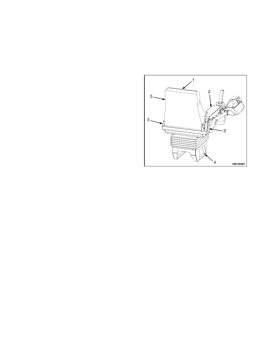
Seat Assembly Removal
NOTE: The seat option can be equipped with an inte-
grated high upper backrest extension. See Figure 2.
NOTE: Use a lifting device for removal of the seat.
1.
Disconnect battery ground lead.
2.
Remove the four mounting bolts and disconnect
armrest assembly from the backside of the seat.
NOTE: Remove the seat together with the mounting
bracket.
3.
Loosen four bolts connecting mounting bracket to
cab.
4.
Remove seat.
1.
HIGH UPPER BACKREST EXTENSION
2.
ARMREST ASSEMBLY
3.
MOUNTING BOLT LOCATIONS
4.
BOLTS (HIDDEN)
5.
OPERATOR SEAT
Figure 2. Operator Seat
Armrest
ADJUST
1.
The armrest can be repositioned to the front or
rear by using the rear lever under the armrest.
2.
The joystick can be positioned to the front or rear
by using the front lever under the armrest.
Steering Column Repair
REMOVE
1.
Disconnect battery ground lead.
2.
Remove the left and right cover under the steer-
ing column.
3.
Remove four hex bolts that holds the steering
control unit to the mount of the steering column
assembly. See Figure 3.
4.
Remove the four cab mounting bolts holding
steering column to the cab floor.
5.
Remove steering column.
3
Steering Column Repair
100 SRM 1177
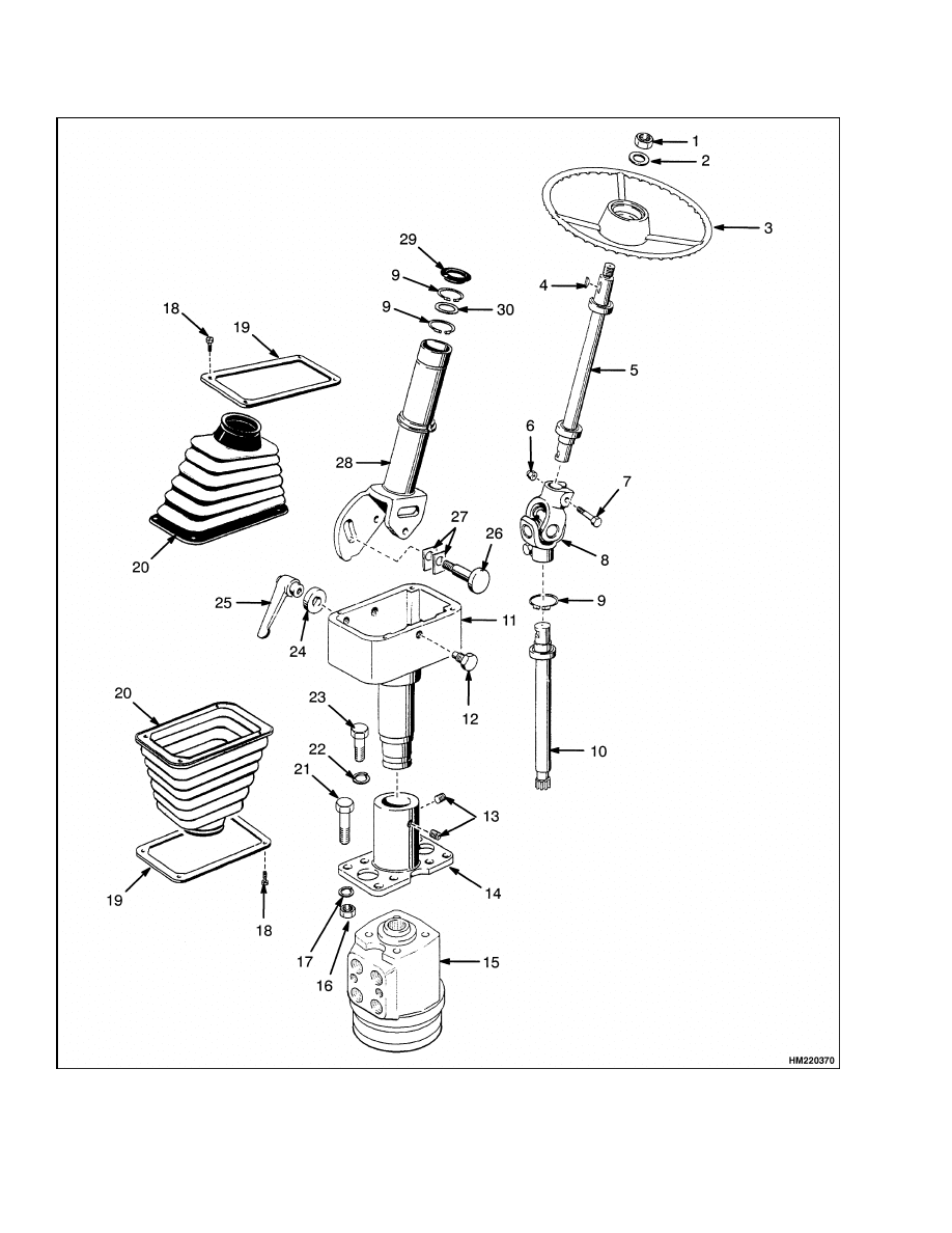
Figure 3. Steering Column
4
100 SRM 1177
Window Wipers Replacement
Legend for Figure 3
1.
NUT
2.
WASHER
3.
STEERING WHEEL
4.
WOODRUFF KEY
5.
UPPER SHAFT ASSEMBLY
6.
LOCK NUT
7.
HEX HEAD BOLT
8.
UNIVERSAL JOINT
9.
SNAP RING
10. LOWER SHAFT ASSEMBLY
11. STEERING HOUSING
12. SCREW
13. SETSCREW
14. MOUNT
15. STEERING CONTROL UNIT
16. NUT
17. LOCKWASHER
18. SCREW
19. JOINT
20. RUBBER BOOT
21. HEX HEAD BOLT
22. LOCKWASHER
23. HEX HEAD BOLT
24. WASHER
25. HANDLE
26. PIN
27. LINING
28. UPPER TUBE
29. RING
30. RING
DISASSEMBLE AND ASSEMBLE
See the section Steering System 1600 SRM 1183 for
the detailed disassemble and assemble information.
INSTALL
1.
Install the lower shaft assembly into the steering
control unit.
2.
Carefully mount the steering control unit with
four hex bolts to allow a non-forced coupling be-
tween steering control unit and steering column.
3.
Install the four cab mounting bolts that hold the
mount (steering column) to the cab floor.
4.
Install the left and right cover under the steering
column.
5.
Connect battery ground lead.
Window Wipers Replacement
Two window wiper motor assemblies are installed in
the operator compartment. A third window wiper
motor is installed on the back of the operators com-
partment. The front window has two double-wiper
arms connected to a single wiper blade. The wiper
motor is installed inside the operator’s cab at the
right front side. The top window is provided with a
wiper motor assembly that has one wiper arm with
wiper blade. The rear window is provided with a
wiper motor assembly that has one wiper arm with
wiper blade. A washer system for all wipers is avail-
able.
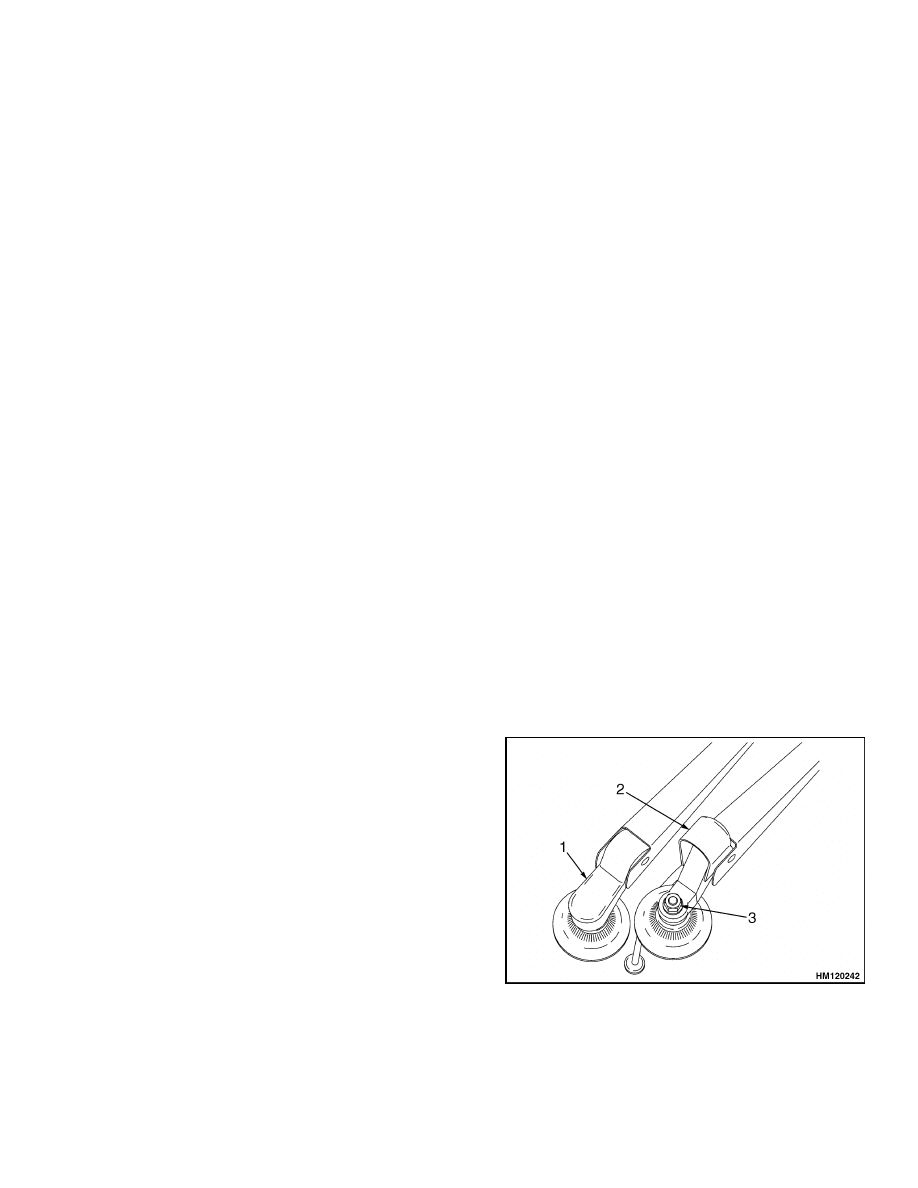
WINDOW WIPER ASSEMBLY
Replace
1.
Lift cover. See Figure 4.
2.
Loosen and remove nut and washer from the
threaded shaft tube.
3.
Mark position of blade on window.
4.
Disconnect wiper.
5.
Disconnect washer hose if applicable.
6.
Install new wiper assembly. Verify that wiper
assembly is properly positioned to give optimal
coverage of the window. Proceed in reverse order.
1.
COVER
2.
COVER OPEN
3.
NUT WITH
WASHER
Figure 4. Wiper Assembly
5
Window Replacement
100 SRM 1177
FRONT, REAR, AND TOP WINDOW WIPER
MOTOR ASSEMBLY
Replace
1.
Disconnect battery ground lead.
2.
Remove wiper assembly. See Window Wiper As-
sembly, Replace.
3.
Remove cover of motor assembly unit.
4.
Disconnect connector.
5.
Remove nuts and washers.
6.
Remove motor assembly.
7.
Install new motor assembly. Proceed in reverse
order.
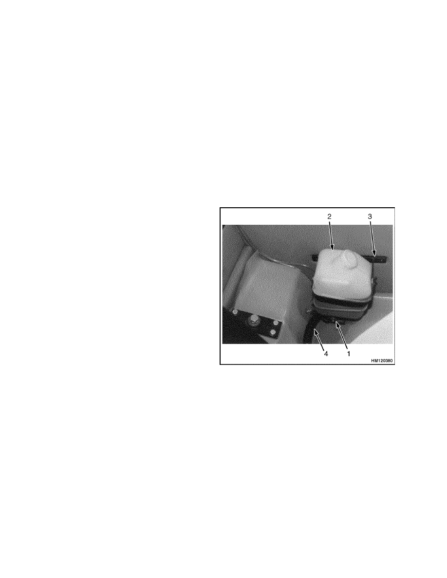
Window Washer Motors and Pumps
REPAIR
NOTE: For the operation and location of window
wiper and washer operating switches, see Instru-
ment Panel, Indicators, and Senders 2200 SRM
1178.
NOTE: Three window washer motors with pump as-
semblies are attached to the water reservoir. See Fig-
ure 5.
NOTE: When replacing washer motor(s), verify that
water hose(s) is connected to proper pump(s).
1.
Disconnect the electrical cable from the reservoir
connector.
2.
Disconnect the three supply hoses located at the
bottom of the reservoir from the motor pumps.
3.
Put tags on the hoses and motor pumps for iden-
tification.
4.
Remove the washer reservoir from its mounting.
5.
Replace damaged part.
6.
Install the washer reservoir into its mounting.
7.
Connect the three supply hoses at the bottom of
the reservoir to the motor pumps according the
tags.
8.
Connect the electrical cable to the reservoir con-
nector.
9.
Check for leaks and proper function.
1.
MOTOR/PUMP
2.
RESERVOIR
3.
BRACKET
4.
WIRING HARNESS
Figure 5. Window Washer System
Window Replacement
FRONT WINDOW, REPLACE
1.
Remove the front wiper assembly. See Window
Wiper Assembly, Replace.
2.
Remove the string from the rubber seal.
NOTE: If the seal is damaged, replace the seal.
3.
Remove the front window from the seal.
Remove the seal from the operator’s compart-
ment opening.
5.
Install the rubber around the window.
6

100 SRM 1177
Window Replacement
6.
Insert a plastic thread (insulated electrical wire)
approximately 3 mm (0.118 in.) in slot of rubber
seal (cab side slot).
7.
Position and press window against frame.
8.
Pull out (cab side slot) plastic thread. This will
ensure that the slot of rubber seal slides properly
over window frame.
9.
Press front window firmly into place.
10. Insert string.
11. Install the front wiper assembly. See Window
Wiper Assembly, Replace.
REAR WINDOW, REPLACE
1.
Remove the rear wiper assembly. See Window
Wiper Assembly, Replace.
2.
Proceed as per instructions for the front window.
See Front Window, Replace.
3.
Install the rear wiper assembly.
See Window
Wiper Assembly, Replace.
TOP WINDOW, REPLACE
1.
Remove the top wiper assembly.
See Window
Wiper Assembly, Replace.
2.
Remove caps and screws.
3.
Remove screws out of the brackets.
4.
Remove left, right, and rear bracket.
5.
Remove the window.
6.
Remove all adhesive sealant from the window
opening and the cross bar.
7.
Add new adhesive sealant on top of the operator’s
compartment around the window opening.
8.
Position the window onto the adhesive sealant
with the holes inline with the mounting points.
9.
Mount and tighten the screws into the mounting
holes at the front and rear corners.
10. Place caps onto the screws.
11. Install the left, right, and rear bracket.
12. Install the top wiper assembly.
See Window
Wiper Assembly, Replace.
SIDE WINDOW, REPLACE
1.
Remove the clamps holding the side window
against the seal of the operator’s compartment.
2.
Remove the side window.
3.
Clean the seal in the opening of the operator’s
compartment.
4.
Position the window against the seal.
5.
Install the clamps holding the side window
against the seal of the operator’s compartment.
DOOR WINDOW, REPLACE
Bottom Window
Remove the door assembly from the operator’s
compartment.
2.
Remove the window from the opening of the door.
3.
Remove the glue and clean the opening of the
door.
4.
Add new glue around the opening of the door.
5.
Place the window carefully into place.
Press the window into the glue, and wait until
window is secured.
7.
Install the door assembly to the operator’s com-
partment.
Sliding Window
NOTE: The sliding window frame is a fully-closed sys-
tem. It is not possible to exchange a sliding window.
When a new sliding window has to be installed the
complete frame assembly has to be replaced.
1.
Remove the rubber at the outside of the frame on
the outside of the door.
2.
Take out the complete sliding window frame from
the door.
3.
Remove the glue/sealant and clean the opening
of the door.
4.
Add new glue/sealant around the opening of the
door.
5.
Place the new sliding window frame carefully
into place.
7

Heater Assembly
100 SRM 1177
6.
Press the sliding window frame into the glue/
sealant, and wait until the frame is secured.
7.
Install the rubber at the outside of the frame on
the outside of the door.
Door Handle Assembly
The door handle assembly is built up by three com-
ponents:
• Outside handle with lock.
• Inside lever type handle and latch mechanism.
• Plastic cover.
REMOVE
1.
Remove the capscrew from the inside door handle
to remove the plastic cover.
2.
Remove a small plastic plate of the inside door
handle to have access to a capscrew.
3.
Remove two capscrews to remove the inside door
handle.
4.
Remove two bolts from the inside of the cab to
remove the outside door handle.
INSTALL
1.
Install the outside door handle.
2.
Install the inside door handle.
3.
Install the small plastic plate onto the inside door
handle.
4.
Install the plastic cover.
Heater Assembly
REMOVE
WARNING
Before removing heater hoses, verify that suf-
ficient time has been given for heater hoses to
cool down. Hot water may cause severe burns.
WARNING
When replacing engine heater hoses, verify
that replacement hoses meet correct specifi-
cations. Failure to meet correct specifications
may cause personal injury.
NOTE: The fuse protecting the heater is located in-
side the fuse panel, located in the fuel tank platform
(right side of the frame).
1.
Disconnect battery ground lead.
2.
Disconnect the heater control cable from the wa-
ter control valve.
3.
Remove the two screws and disconnect the
bracket on top of the heater at the operator’s cab
side.
NOTE: Do not remove the bolts in the below proce-
dure.
4.
Loosen the two bolts on the left and right side.
5.
Rotate the heater to the front side to gain access
to the electrical wires and hoses at the rear side.
6.
Disconnect the heater hoses from the rear of the
heater assembly.
7.
Disconnect the air duct hoses and heater intake
from the heater.
8.
Disconnect the heater wiring harness from the
heater.
9.
Remove the two bolts on the left and right side.
10. Remove the heater.
8
100 SRM 1177
Heater Assembly
INSTALL
1.
Place the heater in position and mount with
the two bolts on the left and right side. Do not
tighten.
2.
Rotate the heater to the front side.
3.
Connect the heater wiring harness to the heater.
4.
Connect the air duct hoses and heater intake to
the heater.
5.
Connect the heater hoses at the rear of the
heater.
6.
Rotate the heater to its correct position and
tighten the two bolts on the left and right side of
the heater.
7.
Using the two screws, connect the bracket on top
of the heater to the operator’s cab.
8.
Connect the heater control valve to the water
control valve.
9.
Connect battery ground lead.
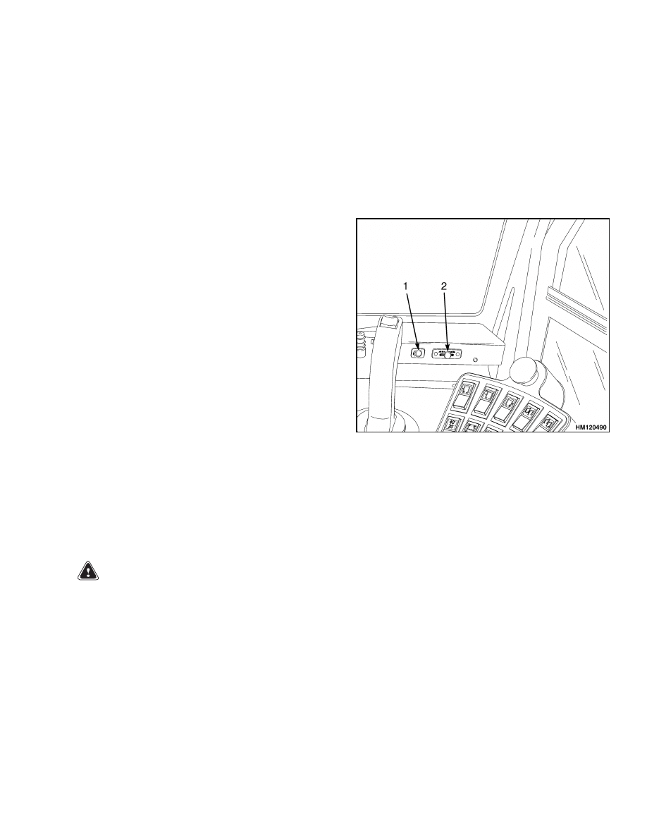
HEATER CONTROL KNOB
Switches
The fuse protecting the heater is located inside the
fuse panel, located in the fuel tank platform (right
side of the frame). See Figure 6 for the heater control
switches.
Cable
Adjust
WARNING
To prevent personal injury, adjust the heater
control valve cable with the heater turned OFF.
NOTE: The heat control knob is mechanically coupled
via a cable to the heater control valve. After replac-
ing the cable or associated item, adjustment of the
cable is required.
1.
Shift the heat control knob to the full hot (Red)
position.
2.
Move the water valve to the open position.
3.
Fasten the cable clips.
1.
HEATER FAN SPEED
2.
HEATER TEMPERATURE CONTROL
Figure 6. Heater Control Switches
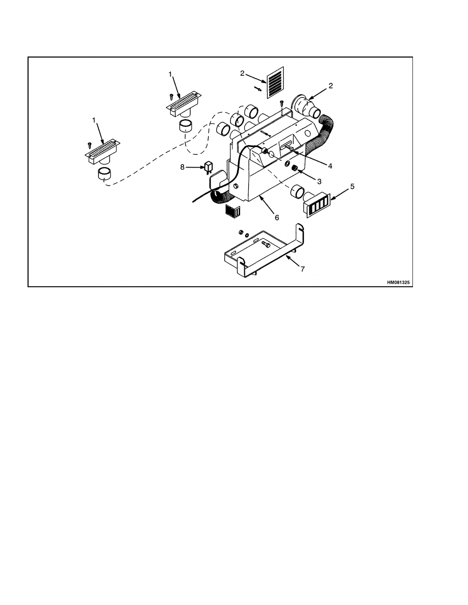
HEATER COMPONENTS
Replace
The heater components for the operator compart-
ment are the heater core, fan, and filter.
These
components are in a sealed housing and are replaced
as a unit. See Figure 7.
9
Instruments, Switches, and Controls
100 SRM 1177
1.
DEFROST VENT
2.
AIR INLET
3.
FAN SPEED KNOB
4.
HEAT CONTROL LEVER
5.
HEATER VENT
6.
HEATER UNIT
7.
HEATER MOUNT BRACKET
8.
RESISTOR
Figure 7. Heater Components
Instruments, Switches, and Controls
NOTE: The instruments and switches are fastened to
the instrument console. Disconnect the wiring har-
ness and remove the screws that hold the panels to
the instrument panel. See the section Diagrams,
Tier 1 Engine 8000 SRM 952 first used on 1533 up
to 1562, 1564, 1565, and 1569 or Diagrams, Tier
2 Engine 8000 SRM 1182 first used on 1563, 1566,
1567, 1568, 1570, and up. These diagrams will help
identify the wiring harnesses and components.
For the replacement of gauges, see the section In-
strument Panel, Indicators, and Senders 2200
SRM 1178.
NOTE: The rocker switches are replaced by press-
ing in on flexible tabs at back side to release switch
assembly from instrument panel. The replacement
switch is installed from top side of instrument panel
and pressed in until tabs on the switch lock in the
opening for the switch.
For the location and operation of the instruments,
switches, and controls, see the Operating Manual.
10

100 SRM 1177
Label Replacement
Label Replacement
WARNING
Labels that have WARNINGS or CAUTIONS
must be replaced if they are damaged. If a mast
of a different size or an accessory carriage is
installed, the capacity rating can change.
Changes in the kind of drive tires can change
the capacity rating.
See a dealer for Hyster
ReachStackers for a replacement nameplate.
The nameplate information is a safety item
and must be correct for the equipment and
configuration of the ReachStacker
®
.
1.
Verify surface is dry and free of oil or grease. Do
not use solvent on new paint. Clean the surface
of old paint using cleaning solvent.
2.
Remove paper from back of label. Do not touch
adhesive surface.
3.
Carefully hold label in correct position above sur-
face. Label cannot be moved after it touches sur-
face. Put label on surface. Verify all air is re-
moved from under label and corners and edges
are tight.
See Parts Manual for correct location and part num-
ber.
11

NOTES
____________________________________________________________
____________________________________________________________
____________________________________________________________
____________________________________________________________
____________________________________________________________
____________________________________________________________
____________________________________________________________
____________________________________________________________
____________________________________________________________
____________________________________________________________
____________________________________________________________
____________________________________________________________
____________________________________________________________
____________________________________________________________
____________________________________________________________
____________________________________________________________
____________________________________________________________
____________________________________________________________
____________________________________________________________
____________________________________________________________
12


TECHNICAL PUBLICATIONS
100 SRM 1177
3/05 Printed in United Kingdom
Document Outline
- toc
Wyszukiwarka
Podobne podstrony:
1586985 2200SRM1178 (03 2005) UK EN
897953 1600SRM0639 (03 2005) UK EN
1598459 1900SRM1213 (03 2005) UK EN
1596602 0100SRM1200 (07 2005) UK EN
897956 1900SRM0642 (03 2005) UK EN
1482603 0100SRM0793 (03 2000) UK EN
897963 4500SRM0649 (03 2005) UK EN
1573930 0600SRM1172 (03 2005) UK EN
897345 1400SRM0413 (03 2005) UK EN
1531815 1800SRM1040 (03 2005) UK EN
899782 2000SRM0077 (03 2005) UK EN
897875 8000SRM0616 (03 2005) UK EN
897961 2200SRM0647 (03 2005) UK EN
1597925 0700SRM1211 (03 2005) UK EN
1466169 4000SRM0741 (03 2005) UK EN
1495208 8000SRM0949 (03 2005) UK EN
1458783 8000SRM0592 (03 2005) UK EN
więcej podobnych podstron