CUMMINS DIESEL
ENGINE FAULT CODE
GUIDE
H40.00-52.00XM-16CH
(H1050, 1150HD-CH) [E117]; RS45-27CH,
RS45-30CH, RS45-27IH, RS46-33CH, RS46-30IH,
RS46-36CH, RS46-33IH First Used on 1563,
1566, 1567, 1568, 1570, and Up [A222]
PART NO. 1573930
600 SRM 1172

SAFETY PRECAUTIONS
MAINTENANCE AND REPAIR
• When lifting parts or assemblies, make sure all slings, chains, or cables are correctly
fastened, and that the load being lifted is balanced. Make sure the crane, cables, and
chains have the capacity to support the weight of the load.
• Do not lift heavy parts by hand, use a lifting mechanism.
• Wear safety glasses.
• DISCONNECT THE BATTERY CONNECTOR before doing any maintenance or repair
on electric lift trucks. Disconnect the battery ground cable on internal combustion lift
trucks.
• Always use correct blocks to prevent the unit from rolling or falling. See HOW TO PUT
THE LIFT TRUCK ON BLOCKS in the Operating Manual or the Periodic Mainte-
nance section.
• Keep the unit clean and the working area clean and orderly.
• Use the correct tools for the job.
• Keep the tools clean and in good condition.
• Always use HYSTER APPROVED parts when making repairs. Replacement parts
must meet or exceed the specifications of the original equipment manufacturer.
• Make sure all nuts, bolts, snap rings, and other fastening devices are removed before
using force to remove parts.
• Always fasten a DO NOT OPERATE tag to the controls of the unit when making repairs,
or if the unit needs repairs.
• Be sure to follow the WARNING and CAUTION notes in the instructions.
• Gasoline, Liquid Petroleum Gas (LPG), Compressed Natural Gas (CNG), and Diesel fuel
are flammable. Be sure to follow the necessary safety precautions when handling these
fuels and when working on these fuel systems.
• Batteries generate flammable gas when they are being charged. Keep fire and sparks
away from the area. Make sure the area is well ventilated.
NOTE: The following symbols and words indicate safety information in this
manual:
WARNING
Indicates a condition that can cause immediate death or injury!
CAUTION
Indicates a condition that can cause property damage!

Cummins Diesel Engine Fault Code Guide
Table of Contents
TABLE OF CONTENTS
General ...............................................................................................................................................................
Description .........................................................................................................................................................
Base Control System .....................................................................................................................................
Fault Code Snapshot Data ............................................................................................................................
Maintenance Monitor (A222 Only) ...................................................................................................................
General ...........................................................................................................................................................
Electronic Throttle Calibration .........................................................................................................................
Electronic Throttle Calibration Procedure...................................................................................................
Fault Codes ........................................................................................................................................................
General ...........................................................................................................................................................
E117................................................................................................................................................................
Access .........................................................................................................................................................
Exit.............................................................................................................................................................
A222................................................................................................................................................................
Access .........................................................................................................................................................
Exit.............................................................................................................................................................
This section is for the following models:
H40.00-52.00XM-16CH (H1050, 1150HD-CH) [E117];
RS45-27CH, RS45-30CH, RS45-27IH, RS46-33CH, RS46-30IH, RS46-36CH,
RS46-33IH First Used on 1563, 1566, 1567, 1568, 1570, and Up [A222]
©2005 HYSTER COMPANY
i

"THE
QUALITY
KEEPERS"
HYSTER
APPROVED
PARTS

600 SRM 1172
Description
General
This section covers the base control system, electronic throttle calibration, and the dash display fault codes for
the Cummins diesel engine.
Description
BASE CONTROL SYSTEM
The engine control system is an electronically-oper-
ated fuel control system that also provides many op-
erator, vehicle, or equipment features.
The base functions of the control system include fu-
eling and timing control, limiting the engine speed
operating range between the low and high idle set
points, and reducing exhaust emissions while opti-
mizing engine performance. The system can also con-
trol the engine brakes, up to two cooling fans, an air
compressor, and a powershift transmission.
The control system uses inputs from the operator and
its sensors to determine the fueling and timing re-
quired to operate at the desired engine speed.
The electronic control module (ECM) is the control
center of the system. It processes all of the inputs
and sends commands to the fuel system, vehicle, and
engine control devices.
The ECM performs diagnostic tests on most of its cir-
cuits and will activate a fault code if a problem is de-
tected in one of these circuits. Along with the fault
code identifying the problem, a snapshot of engine
operating parameters at the time of fault activation
is also stored in memory.
Active fault codes will cause a diagnostic light to
come ON and alert the operator.
The control system utilizes a number of sensors to
provide information on engine operating parameters.
These sensors include the following:
• Coolant Temperature Sensor
• Intake Air Temperature Sensor
• Intake Manifold Pressure Sensor
• Oil Pressure/Temperature Sensor
• Engine Position Sensor
• Ambient Air Pressure Sensor
• Fuel Inlet Restriction Sensor
The following inputs are provided by original equip-
ment manufacturer (OEM) selected devices:
• Accelerator Pedal Position Sensor
• Idle Validation Switch
• Diagnostic Switch (E117 only)
• Increment/Decrement Switch (E117 only)
FAULT CODE SNAPSHOT DATA
This is additional fault code information, which can
be obtained by using INSITE™. The snapshot data
records the value or state of the control system sen-
sors and switches at the time a fault occurred. This
data is stored for the first occurrence of the fault,
since it was last cleared, and the most recent occur-
rence. This data can be very valuable when trying to
recreate or determine engine operating conditions at
the time of a fault.
The operator or technician can create a snapshot of
the engine’s operating conditions and the state of the
control system’s sensors and switches. This is per-
formed using the diagnostic switch while the engine
is running.
1

Fault Codes
600 SRM 1172
Maintenance Monitor (A222 Only)
GENERAL
The maintenance monitor (oil change monitor) fea-
ture provides a method of monitoring the oil change
interval in the engine and signaling the operator
when an oil change is needed.
The maintenance
monitor counts the hours of engine operation and
subtracts this from the oil change interval time.
The maintenance monitor feature also allows for
extended oil change intervals when the customer is
using such products as Premium Blue 2000. Pro-
gramming tools can be used to display the percent of
the current interval that has been consumed.
When a certain calibrated percentage of the oil
change interval time has been used, the mainte-
nance light will flash when the key is turned to ON
and a warning flag is set.
Electronic Throttle Calibration
The electronic throttle calibration is advised after
any throttle adjustment or throttle sensor replace-
ment. It is also advised when the main power has
been disconnected, such as changing the batteries or
disconnecting the batteries for maintenance.
ELECTRONIC THROTTLE CALIBRATION
PROCEDURE
1.
Turn the ignition ON.
2.
Press the throttle slowly to maximum throttle,
and then fully release the throttle.
3.
Repeat this procedure three times.
NOTE: Not performing the calibration will generate
the fault code E0431, but eventually the performance
of the lift truck (E117) or ReachStacker
®
(A222) will
return to normal operation.
Fault Codes
GENERAL
The control system can show and record operation
anomalies, which present themselves as fault codes.
These codes will make troubleshooting easier. The
fault codes are recorded in the engine control module
(ECM). They can be read using the fault lights in the
cab panel or with INSITE™.
The two types of fault codes are as follows:
• Engine electronic control fault codes: A fault has
been detected with the engine or control system.
• Information codes: An event that could provide im-
portant information has occurred with the engine
or control system.
All fault codes recorded will either be active (fault
code is currently active on the engine) or inactive
(fault code was active at some time, but is not cur-
rently active).
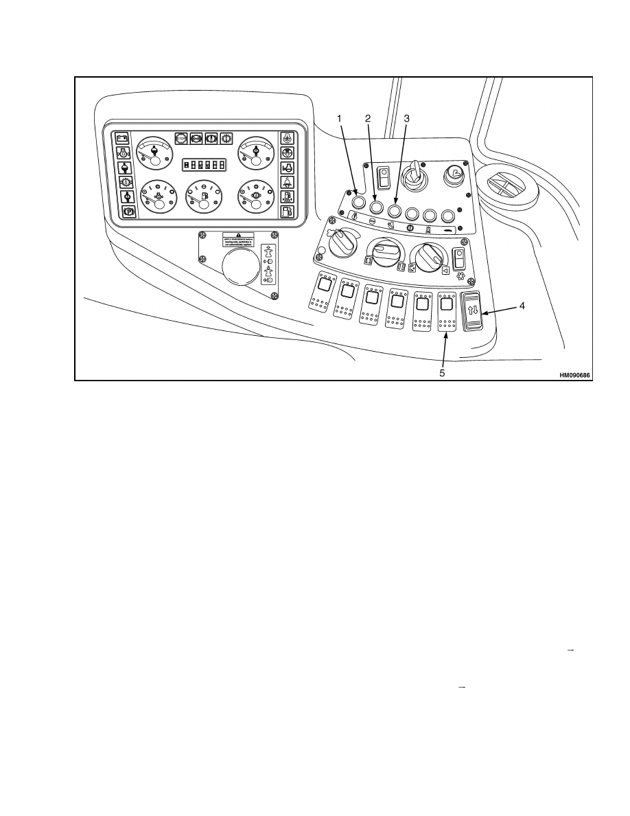
The warning light is yellow and indicates the need
to repair the fault at the first available opportunity.
See Figure 1 or Figure 2.
The stop light is red and indicates the need to stop
the engine as soon as it can be safely done. The en-
gine should remain shut down until the fault can be
repaired. See Figure 1 or Figure 2.
The maintenance light will be ON when some type
of maintenance is required. This light could indicate
water in the fuel filter, low crankcase oil level, low
coolant level, high coolant temperature, high intake
air temperature, or high oil temperature. See Fig-
ure 1 or Figure 2.
2
600 SRM 1172
Fault Codes
1.
YELLOW WARNING LIGHT
2.
RED STOP LIGHT
3.
YELLOW MAINTENANCE LIGHT
4.
DIAGNOSTIC SWITCH
5.
INCREMENT/DECREMENT SWITCH
Figure 1. Error Code Display (E117)
E117
Access
To check for active engine electronic fuel system and
engine protection system fault codes, proceed as fol-
lows:
1.
Place the lift truck on a solid, level surface.
2.
Apply the park brake.
3.
Turn the key switch OFF and move the diagnos-
tic switch to the ON position. See Figure 1.
4.
Turn the lift truck key switch to the ON position.
NOTE: If no active fault codes are recorded, both
lights will be ON and stay ON.
If active fault codes are recorded, both lights will be
ON momentarily, then begin to flash the code of the
recorded faults. For descriptions of error codes, see
Table 1.
The fault code will flash in the following sequence:
1.
First, the yellow warning light will flash. Then,
there will be a short one- or two-second pause.
After that, the number of the recorded fault code
will flash in red. There will be a one- or two-sec-
ond pause between each number. When the num-
ber has finished flashing in red, a yellow light
will appear again. The three-digit code will re-
peat in the same sequence.
2.
The lights flash each fault code out three times
before advancing to the next code. To skip to
the next fault code, move the increment/decre-
ment switch momentarily to the increment (+)
position. See Figure 1. To go back to the pre-
vious fault code, momentarily move the incre-
ment/decrement switch to the decrement ( ) po-
sition. If only one active fault is recorded, the
same fault code will continuously be displayed
when either (+) or ( ) switch is pressed.
3
Fault Codes
600 SRM 1172
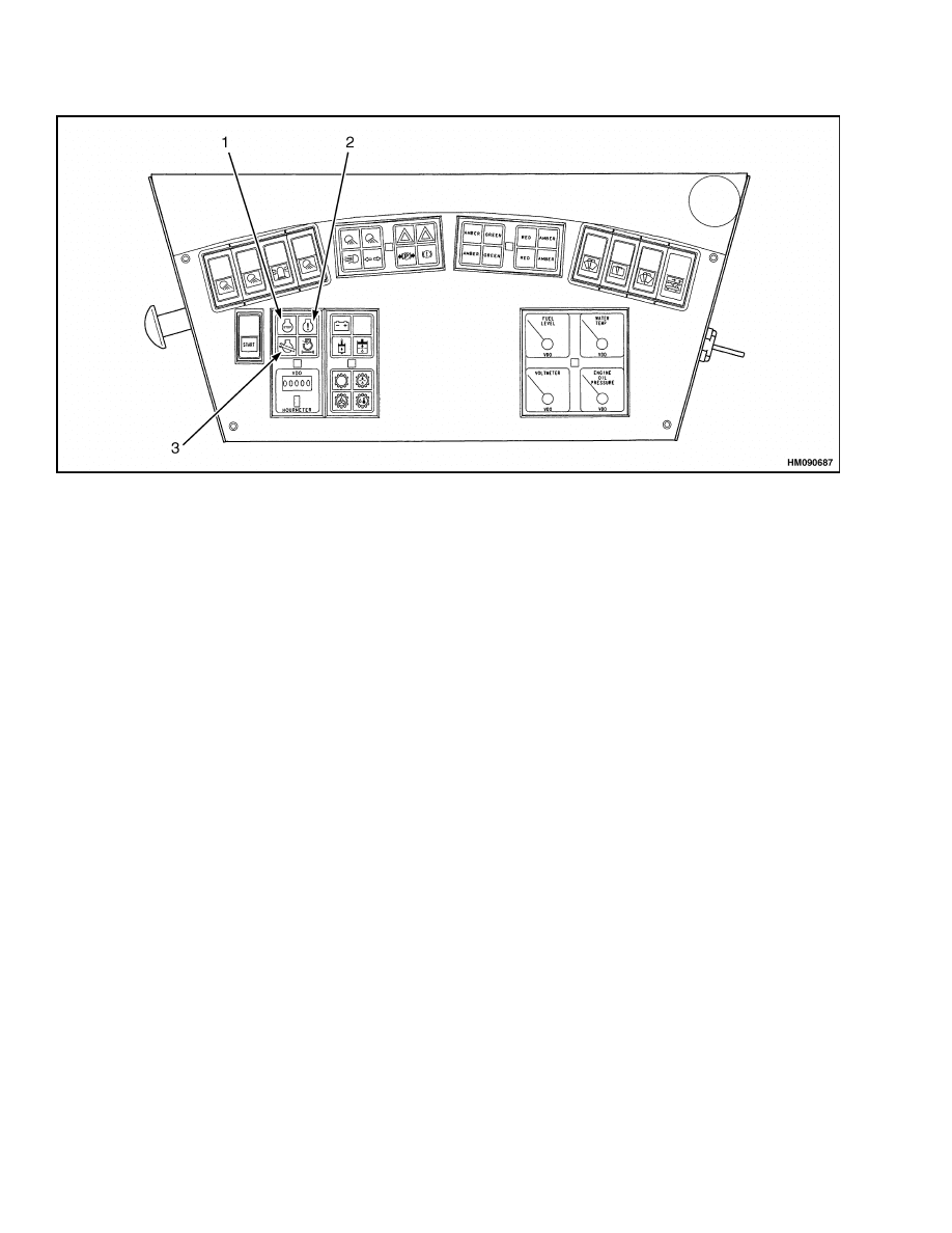
1.
RED STOP LIGHT
2.
YELLOW WARNING LIGHT
3.
YELLOW MAINTENANCE LIGHT
Figure 2. Error Code Display (A222)
Exit
To exit the fault log mode, turn OFF the diagnos-
tic switch. If the diagnostic switch is left ON, some
faults may not be logged by the ECM.
A222
Access
In case of an active fault, indicated by the stop/warn-
ing/maintenance lights, select the diagnostic mode
and proceed as follows:
1.
Place the ReachStacker
®
on a solid, level surface.
2.
Apply the park brake.
3.
Shut down the engine.
4.
Turn the key switch to the ON position.
5.
Operate the throttle pedal three times, this de-
fines the throttle pedal as diagnostic switch.
The warning light will flash once to indicate the start
of the fault code sequence. The stop light will then
flash out a three digit code. Example: flash, flash,
pause indicates the number 2. This process repeats
until the diagnostic mode is switched OFF, or the
throttle pedal is operated. Each time the throttle
pedal is operated the next fault code is flashed by the
stop light. See Figure 2.
Exit
Turn the key switch to the OFF position to leave di-
agnostic mode.
4

600 SRM 1172
Fault Codes
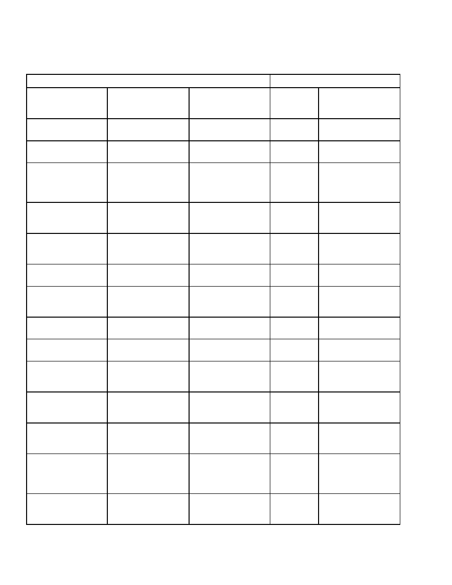
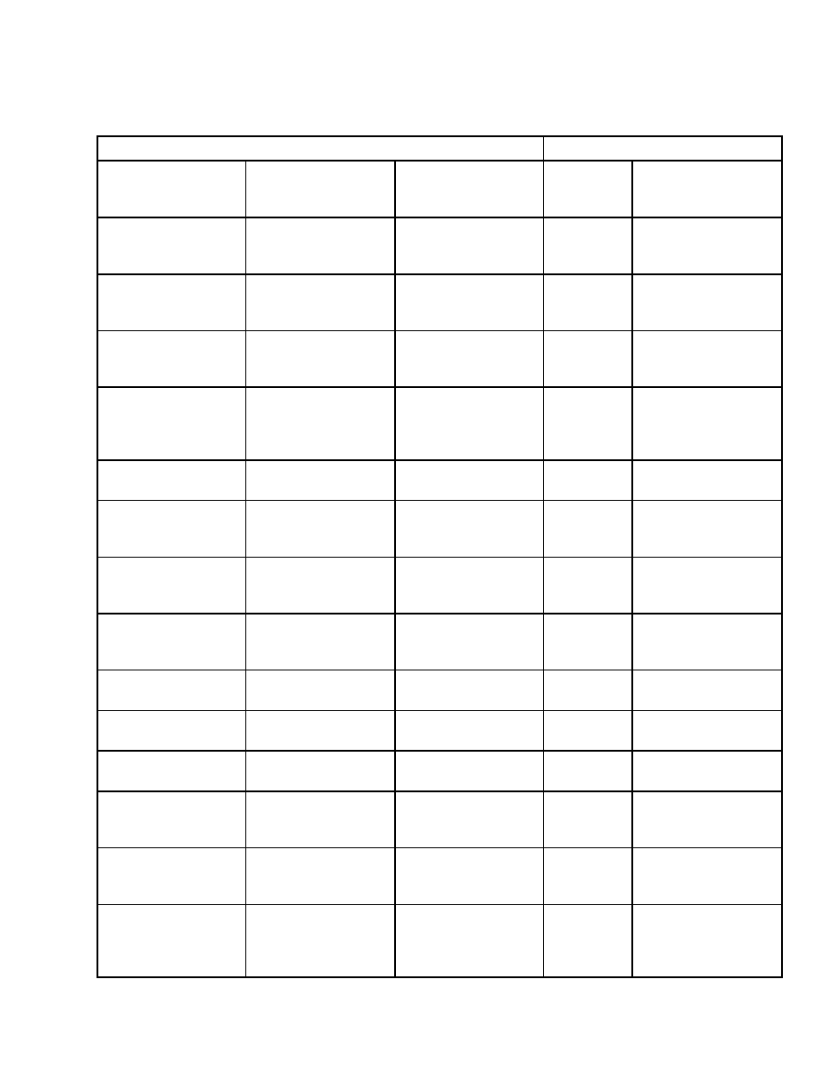
Table 1. Error Code Descriptions
Fault Condition Present/Maintenance Required
Fault Code Readout
Limited Operating
Conditions
Warning Light
Engine Stop
Warning Light
Maintenance
Warning Light
Fault
Code
Description
ON
111
Engine control
module, critical
internal failure.
ON
115
Engine speed/position
sensor circuit, loss of
both signals from
magnetic pickup
sensor.
ON
121
Engine speed/position
sensor circuit, loss of
one signal from the
magnetic pickup
sensor.
ON
122
Intake manifold
pressure sensor #1
circuit, shorted high.
ON
123
Intake manifold
pressure sensor #1
circuit, shorted low.
ON
131
Accelerator pedal
position sensor
circuit, shorted high.
ON
132
Accelerator pedal
position sensor
circuit, shorted low.
ON
133
Remote accelerator
pedal position sensor
circuit, shorted high.
ON
134
Remote accelerator
pedal position sensor
circuit, shorted low.
ON
135
Engine oil pressure
sensor circuit,
shorted high.
ON
141
Engine oil pressure
sensor circuit,
shorted low.
ON
143
Engine oil pressure
low warning.
5

Fault Codes
600 SRM 1172
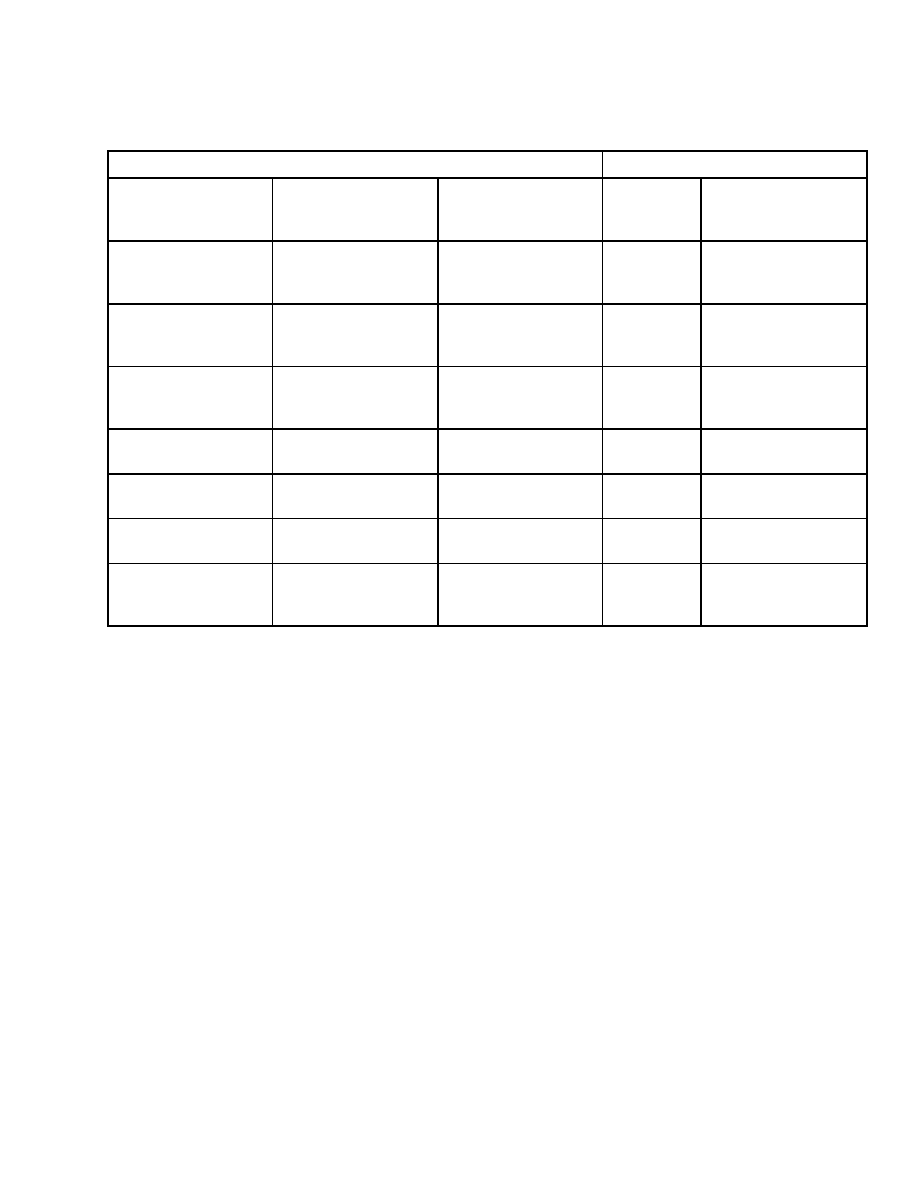
Table 1. Error Code Descriptions (Continued)
Fault Condition Present/Maintenance Required
Fault Code Readout
Limited Operating
Conditions
Warning Light
Engine Stop
Warning Light
Maintenance
Warning Light
Fault
Code
Description
ON
144
Engine coolant
temperature sensor
circuit, shorted high.
ON
145
Engine coolant
temperature sensor
circuit, shorted low.
ON
147
Accelerator pedal
position sensor
circuit, low frequency.
ON
148
Accelerator pedal
position sensor
circuit, high
frequency.
ON
151
Engine coolant
temperature high,
critical.
ON
153
Intake manifold
temperature sensor
#1 circuit, shorted
high.
ON
154
Intake manifold
temperature sensor
#1 circuit, shorted
low.
ON
155
Intake manifold
temperature #1 high,
critical.
187
Sensor supply voltage
#2 circuit, shorted
low.
ON
198
Lamp circuit, high
voltage detected,
when low voltage was
expected.
ON
199
Lamp circuit, low
voltage detected,
when high voltage
was expected.
6

600 SRM 1172
Fault Codes
Table 1. Error Code Descriptions (Continued)
Fault Condition Present/Maintenance Required
Fault Code Readout
Limited Operating
Conditions
Warning Light
Engine Stop
Warning Light
Maintenance
Warning Light
Fault
Code
Description
211
Additional
OEM/Vehicle
diagnostic codes
have been logged.
Check other ECMs
for DTCs.
ON
212
Engine oil
temperature sensor
circuit, shorted high.
ON
213
Engine oil
temperature sensor
circuit, shorted low.
ON
214
Engine oil
temperature high,
critical.
ON
216
Air compressor wet
tank pressure signal
circuit, high voltage.
ON
217
Air compressor wet
tank pressure signal
circuit, low voltage.
ON
218
Air compressor wet
tank pressure signal
circuit, too high or too
low voltage.
219
Low oil level in the
centinel makeup oil
tank.
ON
221
Ambient air pressure
sensor circuit,
shorted high.
ON
222
Ambient air pressure
sensor circuit,
shorted low.
ON
223
Engine oil burn
valve solenoid circuit,
shorted low.
ON
227
Sensor supply voltage
#2 circuit, shorted
high.
7
Fault Codes
600 SRM 1172
Table 1. Error Code Descriptions (Continued)
Fault Condition Present/Maintenance Required
Fault Code Readout
Limited Operating
Conditions
Warning Light
Engine Stop
Warning Light
Maintenance
Warning Light
Fault
Code
Description
ON
234
Engine high speed,
critical.
ON
235
Engine coolant level
low, critical.
ON
237
External speed
input (multiple unit
sychronization), data
incorrect.
ON
241
Vehicle speed
sensor circuit, data
incorrect.
ON
242
Vehicle speed sensor
circuit, tampering
has been detected.
ON
245
Fan clutch circuit,
shorted low.
ON
249
Ambient air
temperature sensor
circuit, high voltage.
ON
254
Fuel shutoff valve
circuit, shorted low.
ON
255
Fuel shutoff valve
circuit, shorted high.
ON
256
Ambient air
temperature sensor
circuit, high voltage.
ON
285
SAE J1939
multiplexing PGN
time-out error.
ON
286
SAE J1939
multiplexing
configuration error.
ON
287
SAE J1939
multiplexing
accelerator pedal
sensor, system error.
ON
288
SAE J1939
multiplexing remote
throttle, data error.
8

600 SRM 1172
Fault Codes
Table 1. Error Code Descriptions (Continued)
Fault Condition Present/Maintenance Required
Fault Code Readout
Limited Operating
Conditions
Warning Light
Engine Stop
Warning Light
Maintenance
Warning Light
Fault
Code
Description
ON
293
Auxiliary
temperature sensor
input #1 circuit,
shorted high.
ON
294
Auxiliary
temperature sensor
input #1 circuit,
shorted low.
ON
295
Ambient air pressure
sensor circuit, data
incorrect.
ON
297
Auxiliary pressure
sensor input #2
circuit, shorted high.
ON
298
Auxiliary pressure
sensor input #2
circuit, shorted low.
ON
299
Engine shutdown
commanded by
J1939.
ON
311
Injector solenoid
valve cylinder #1
circuit, grounded
circuit.
ON
312
Injector solenoid
valve cylinder #5
circuit, grounded
circuit.
ON
313
Injector solenoid
valve cylinder #3
circuit, grounded
circuit.
ON
314
Injector solenoid
valve cylinder #6
circuit, grounded
circuit.
ON
315
Injector solenoid
valve cylinder #2
circuit, grounded
circuit.
9

Fault Codes
600 SRM 1172
Table 1. Error Code Descriptions (Continued)
Fault Condition Present/Maintenance Required
Fault Code Readout
Limited Operating
Conditions
Warning Light
Engine Stop
Warning Light
Maintenance
Warning Light
Fault
Code
Description
ON
319
Real time clock,
power interrupt.
ON
321
Injector solenoid
valve cylinder #4
circuit, open circuit.
ON
322
Injector solenoid
valve cylinder #1
circuit, open circuit.
ON
323
Injector solenoid
valve cylinder #5
circuit, open circuit.
ON
324
Injector solenoid
valve cylinder #3
circuit, open circuit.
ON
325
Injector solenoid
valve cylinder #6
circuit, open circuit.
ON
331
Injector solenoid
valve cylinder #2
circuit, open circuit.
ON
332
Injector solenoid
valve cylinder #4
circuit, open circuit.
ON
338
Idle shutdown vehicle
accessory/ignition
bus relay circuit,
voltage or open circuit
detected.
ON
339
Idle shutdown vehicle
accessory/ignition
bus relay circuit, low
voltage or faulty ECM
output circuit.
ON
341
Engine control
module, data lost.
ON
343
Engine control
module, internal
hardware failure.
10
600 SRM 1172
Fault Codes
Table 1. Error Code Descriptions (Continued)
Fault Condition Present/Maintenance Required
Fault Code Readout
Limited Operating
Conditions
Warning Light
Engine Stop
Warning Light
Maintenance
Warning Light
Fault
Code
Description
ON
349
Transmission output
shaft, speed high
warning.
ON
352
Sensor supply voltage
#1 circuit, shorted
low.
ON
386
Sensor supply voltage
#1 circuit, shorted
high.
ON
387
Accelerator pedal
position sensor
supply voltage circuit,
shorted high.
ON
415
Engine oil pressure
low, critical.
ON
418
Water in fuel
indicator high,
maintenance.
ON
419
Intake manifold
pressure sensor
signal error.
ON
422
Engine coolant level
sensor circuit, data
incorrect.
426
SAE J1939 datalink,
cannot transmit.
ON
428
Water in fuel sensor
circuit, shorted high.
ON
429
Water in fuel sensor
circuit, shorted low.
ON
431
Accelerator pedal idle
validation circuit,
data incorrect.
ON
432
Accelerator pedal idle
validation circuit, out
of calibration.
ON
433
Intake manifold
pressure sensor
circuit, data
incorrect.
11

Fault Codes
600 SRM 1172
Table 1. Error Code Descriptions (Continued)
Fault Condition Present/Maintenance Required
Fault Code Readout
Limited Operating
Conditions
Warning Light
Engine Stop
Warning Light
Maintenance
Warning Light
Fault
Code
Description
ON
434
Power lost without
ignition OFF.
ON
435
Engine oil pressure
sensor circuit, data
incorrect.
ON
441
Battery #1 voltage
low, warning.
ON
442
Battery #1 voltage
high, warning.
ON
443
Accelerator pedal
position sensor
supply voltage circuit,
shorted low.
ON
465
Wastegate actuator
#1 circuit, high
voltage.
ON
466
Wastegate actuator
#1 circuit, low voltage
or faulty ECM output
circuit.
ON
469
Cab thermostat
circuit, E3 will cycle
the engine between
20 minutes RUN and
15 minutes OFF, or
will not autostart
the engine for cab
comfort mode. Will
not be disabled.
ON
471
Low crankcase oil
level.
ON
472
Crankcase oil level
sensor circuit, high or
low voltage.
ON
474
Starter solenoid
lockout relay circuit,
low voltage.
ON
475
Electronic air
compressor governor
circuit, low voltage.
12

600 SRM 1172
Fault Codes
Table 1. Error Code Descriptions (Continued)
Fault Condition Present/Maintenance Required
Fault Code Readout
Limited Operating
Conditions
Warning Light
Engine Stop
Warning Light
Maintenance
Warning Light
Fault
Code
Description
ON
476
Electronic air
compressor governor
circuit, high voltage.
ON
489
Transmission output
shaft (tailshaft),
speed low warning.
ON
491
Wastegate actuator
#2 circuit, high
voltage.
ON
492
Wastegate actuator
#2 circuit, low voltage
or faulty ECM output
circuit.
ON
527
Auxiliary input/
output #2 circuit,
shorted high.
ON
528
OEM alternate
torque validation
switch, data
incorrect.
ON
529
Auxiliary input/
output #3 circuit,
shorted high.
ON
536
Autoshift low gear
actuator circuit, low
voltage detected
when high voltage
commanded or
voltage detected
when no voltage is
commanded.
ON
537
Autoshift high gear
actuator circuit, low
voltage detected
when high voltage
commanded or
voltage detected
when no voltage is
commanded.
13

Fault Codes
600 SRM 1172
Table 1. Error Code Descriptions (Continued)
Fault Condition Present/Maintenance Required
Fault Code Readout
Limited Operating
Conditions
Warning Light
Engine Stop
Warning Light
Maintenance
Warning Light
Fault
Code
Description
ON
538
Autoshift neutral
gear actuator circuit,
low voltage detected
when high voltage
commanded or
voltage detected
when no voltage is
commanded.
ON
541
Starter relay/
interlock circuit
at ECM, incorrect
voltage.
ON
544
Autoshift failure,
at least three shift
attempts were
missed.
ON
551
Accelerator pedal idle
validation circuit,
shorted low.
ON
581
Fuel supply pump
inlet pressure sensor
circuit, shorted high.
ON
582
Fuel supply pump
inlet pressure sensor
circuit, shorted low.
ON
583
Fuel supply pump
inlet pressure low
warning.
ON
588
Engine start alarm
circuit, high voltage
when low voltage was
expected at ECM.
ON
589
Engine start alarm
circuit, low voltage
when high voltage
was expected at
ECM.
ON
595
Turbocharger
overspeed protection
fault.
14
600 SRM 1172
Fault Codes
Table 1. Error Code Descriptions (Continued)
Fault Condition Present/Maintenance Required
Fault Code Readout
Limited Operating
Conditions
Warning Light
Engine Stop
Warning Light
Maintenance
Warning Light
Fault
Code
Description
ON
596
Electrical charging
system voltage high,
warning.
ON
597
Electrical charging
system voltage low,
warning.
ON
598
Electrical charging
system voltage low,
critical.
611
Engine hot,
shutdown.
ON
775
Air system, slow leak
detected.
ON
776
Air system, fast leak
detected.
951
Cylinder power
imbalance between
cylinders.
15

NOTES
____________________________________________________________
____________________________________________________________
____________________________________________________________
____________________________________________________________
____________________________________________________________
____________________________________________________________
____________________________________________________________
____________________________________________________________
____________________________________________________________
____________________________________________________________
____________________________________________________________
____________________________________________________________
____________________________________________________________
____________________________________________________________
____________________________________________________________
____________________________________________________________
____________________________________________________________
____________________________________________________________
____________________________________________________________
____________________________________________________________
16


TECHNICAL PUBLICATIONS
600 SRM 1172
3/05 (8/04)(7/04) Printed in United Kingdom
Document Outline
- toc
- tables
Wyszukiwarka
Podobne podstrony:
897953 1600SRM0639 (03 2005) UK EN
1598459 1900SRM1213 (03 2005) UK EN
897956 1900SRM0642 (03 2005) UK EN
897963 4500SRM0649 (03 2005) UK EN
1586985 2200SRM1178 (03 2005) UK EN
897345 1400SRM0413 (03 2005) UK EN
1531815 1800SRM1040 (03 2005) UK EN
1564053 0600SRM1101 (03 2004) UK EN
899782 2000SRM0077 (03 2005) UK EN
897875 8000SRM0616 (03 2005) UK EN
897961 2200SRM0647 (03 2005) UK EN
1597925 0700SRM1211 (03 2005) UK EN
1586982 0100SRM1177 (03 2005) UK EN
1466169 4000SRM0741 (03 2005) UK EN
1495208 8000SRM0949 (03 2005) UK EN
1458783 8000SRM0592 (03 2005) UK EN
1589731 2200SRM1184 (03 2005) UK EN
1531821 1800SRM1037 (03 2005) UK EN
więcej podobnych podstron