
3B6 LOAD LIMITER
SYSTEM
RS45-27CH, RS45-30CH, RS45-27IH, RS46-33CH,
RS46-30IH, RS46-36CH, RS46-33IH First Used
on 1537 and Up [A222]
PART NO. 1598459
1900 SRM 1213

SAFETY PRECAUTIONS
MAINTENANCE AND REPAIR
• When lifting parts or assemblies, make sure all slings, chains, or cables are correctly
fastened, and that the load being lifted is balanced. Make sure the crane, cables, and
chains have the capacity to support the weight of the load.
• Do not lift heavy parts by hand, use a lifting mechanism.
• Wear safety glasses.
• DISCONNECT THE BATTERY CONNECTOR before doing any maintenance or repair
on electric lift trucks. Disconnect the battery ground cable on internal combustion lift
trucks.
• Always use correct blocks to prevent the unit from rolling or falling. See HOW TO PUT
THE LIFT TRUCK ON BLOCKS in the Operating Manual or the Periodic Mainte-
nance section.
• Keep the unit clean and the working area clean and orderly.
• Use the correct tools for the job.
• Keep the tools clean and in good condition.
• Always use HYSTER APPROVED parts when making repairs. Replacement parts
must meet or exceed the specifications of the original equipment manufacturer.
• Make sure all nuts, bolts, snap rings, and other fastening devices are removed before
using force to remove parts.
• Always fasten a DO NOT OPERATE tag to the controls of the unit when making repairs,
or if the unit needs repairs.
• Be sure to follow the WARNING and CAUTION notes in the instructions.
• Gasoline, Liquid Petroleum Gas (LPG), Compressed Natural Gas (CNG), and Diesel fuel
are flammable. Be sure to follow the necessary safety precautions when handling these
fuels and when working on these fuel systems.
• Batteries generate flammable gas when they are being charged. Keep fire and sparks
away from the area. Make sure the area is well ventilated.
NOTE: The following symbols and words indicate safety information in this
manual:
WARNING
Indicates a condition that can cause immediate death or injury!
CAUTION
Indicates a condition that can cause property damage!

3B6 Load Limiter System
Table of Contents
TABLE OF CONTENTS
General ...............................................................................................................................................................
Description .........................................................................................................................................................
System Components...........................................................................................................................................
Main Unit.......................................................................................................................................................
Load Limiter System (Compact Display Panel)...........................................................................................
Compact Integrated Transducer (Boom Length and Angle Transducer) ...................................................
Pressure Transducers ....................................................................................................................................
Operation (Compact Display Panel) .................................................................................................................
Display ...........................................................................................................................................................
Displays for the Operator..............................................................................................................................
Replace and Adjust ............................................................................................................................................
General ...........................................................................................................................................................
Main Unit.......................................................................................................................................................
Remove.......................................................................................................................................................
Install .........................................................................................................................................................
Load Limiter System Display .......................................................................................................................
Remove.......................................................................................................................................................
Install .........................................................................................................................................................
Compact Integrated Transducer ...................................................................................................................
Remove.......................................................................................................................................................
Install .........................................................................................................................................................
Pressure Transducers ....................................................................................................................................
Remove.......................................................................................................................................................
Install .........................................................................................................................................................
Angle Potentiometer......................................................................................................................................
Boom Angle Calibration............................................................................................................................
Length Potentiometer....................................................................................................................................
Boom Length Calibration..........................................................................................................................
Diagnostics .........................................................................................................................................................
Printer Options ..................................................................................................................................................
Troubleshooting..................................................................................................................................................
This section is for the following models:
RS45-27CH, RS45-30CH, RS45-27IH, RS46-33CH, RS46-30IH, RS46-36CH,
RS46-33IH First Used on 1537 and Up [A222]
©2005 HYSTER COMPANY
i

"THE
QUALITY
KEEPERS"
HYSTER
APPROVED
PARTS
1900 SRM 1213
Description
General
This section has the description and repair proce-
dures for the 3B6 Load Limiter System components.
The instructions for the diagnostics, printer options,
and troubleshooting are also included in this section.
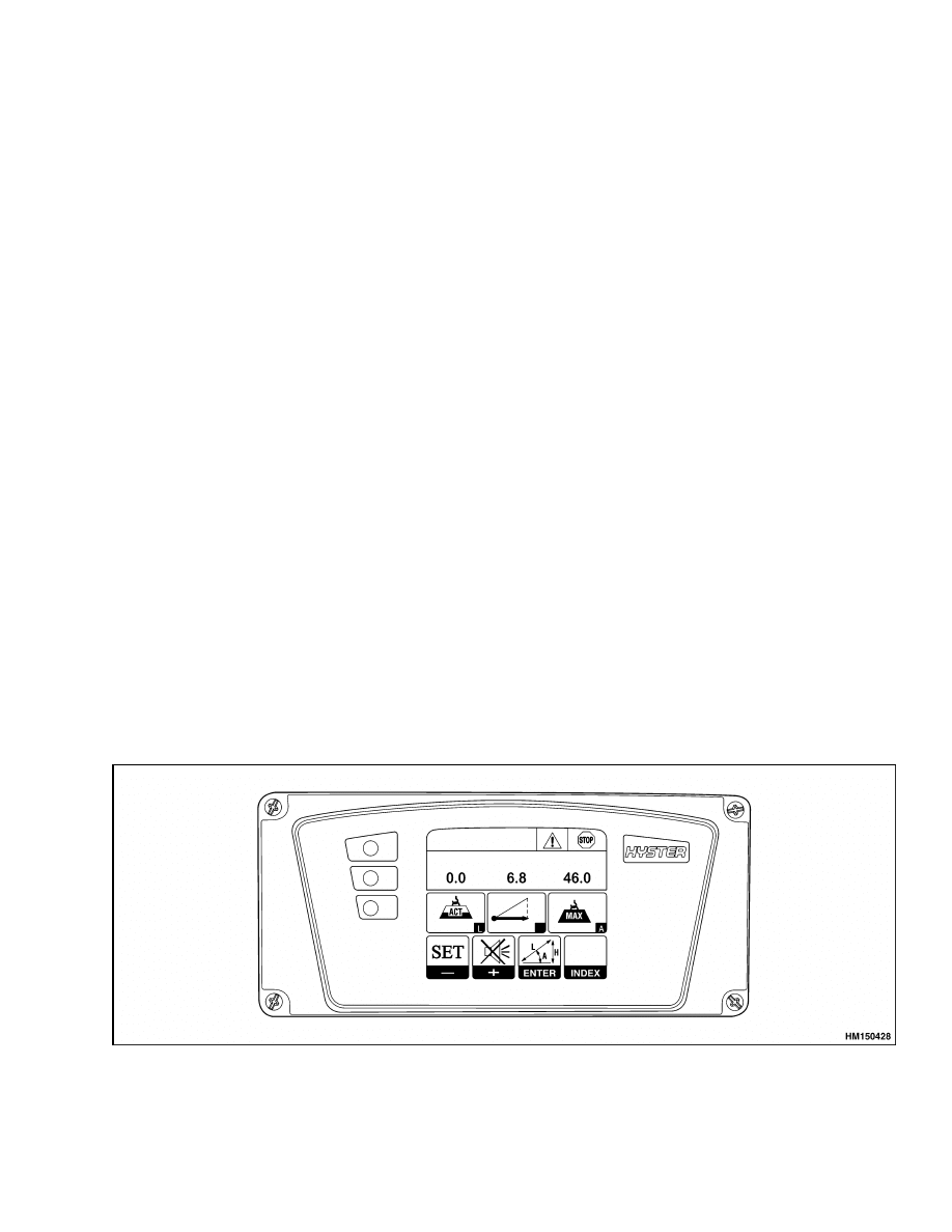
Description
The Load Limiter System is a 3B6 Load Limiter Sys-
tem. It is an electronic load limiter system designed
to indicate the allowable lifting capacity of the Reach-
Stacker
®
. The display panel is shown in Figure 1 and
the four main system components are shown in Fig-
ure 2.
Each Load Limiter System is factory programmed to
match the specific ReachStacker to which it is at-
tached. By programming the unit with the informa-
tion requested during the start up sequence, the sys-
tem monitors and displays the following:
• Actual lifted load
• Maximum admitted load
• Tilting percentage
• Operating radius of the load
• Boom angle
• Boom extension
• Working mode
• Warning lights (green, yellow, red) and buzzer
The system continually monitors output from the
pressure transducers and compact integrated trans-
ducer. It integrates the programmed inputs from the
display panel switches, pressure transducers, and
compact integrated transducer and compares this
information to the manufacturer’s capacity charts,
which are stored in the main unit of the Load Lim-
iter System.
The resulting data is displayed for the operator. If
an overload condition is determined, the operator is
warned with an audible and visual alarm and the hy-
draulic functions used to create the overload condi-
tions are disabled. The hydraulic functions to correct
the overload condition are still enabled.
The lifted load is continuously compared with the
maximum allowable load obtained from the manu-
facturer’s capacity charts, and consequently three
possible situations can occur as follows:
• Green lamp is ON, no acoustic signal is produced.
The lifted load is lower than 90% of the maximum
load.
• Yellow light is ON and the buzzer sounds intermit-
tently. This is the warning situation. The signal
intervenes when the lifted load is more than 90%
and less than 100% of the maximum load.
• Red light is ON and buzzer sounds continuously.
The lifted load exceeds the allowable load so the
maneuvers shutdown function is activated.
In
alarm situation, only the maneuvers allowing the
crane to go back from the danger situation are
allowed.
Figure 1. 3B6 Load Limiter System
1
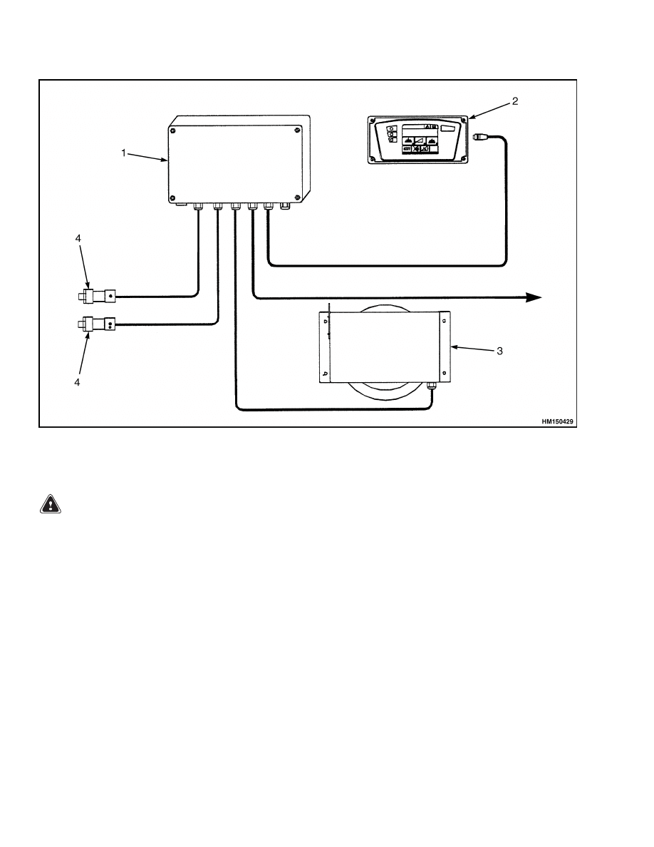
System Components
1900 SRM 1213
1.
MAIN UNIT U2MIC
2.
DISPLAY IDR
3.
COMPACT INTEGRATED TRANSDUCER ACT II
4.
PRESSURE TRANSDUCER
Figure 2. System Components
WARNING
Use caution when using the override function.
Using the incorrect function can cause damage
to the ReachStacker and can cause personal in-
jury.
There is an override system available on the Reach-
Stacker. By using the override system the shut down
function can be reset, and all functions are opera-
tional again.
System Components
MAIN UNIT
The main unit is equipped with memory for data and
program storage. There are two types of memory
storage, (EPROM) for load table storage and erasable
type (EEPROM) for setting data storage. The main
unit input/output signals are self-protected against
overloads and short circuits.
LOAD LIMITER SYSTEM (COMPACT
DISPLAY PANEL)
During operation, the system measures the angle
and length of the boom and the weight of the load.
The information about the load is shown on the
display screen above the instrument panel. The sys-
tem has an automatic shutoff that activates when
the load moment increases beyond the factory set
limits. Load moment is a combination of the weight
2
1900 SRM 1213
System Components
of the load and its relationship to the front axle. The
load moment is increased by extending or lowering
the boom and load and decreased by retracting and
raising the boom and load.
COMPACT INTEGRATED TRANSDUCER
(BOOM LENGTH AND ANGLE
TRANSDUCER)
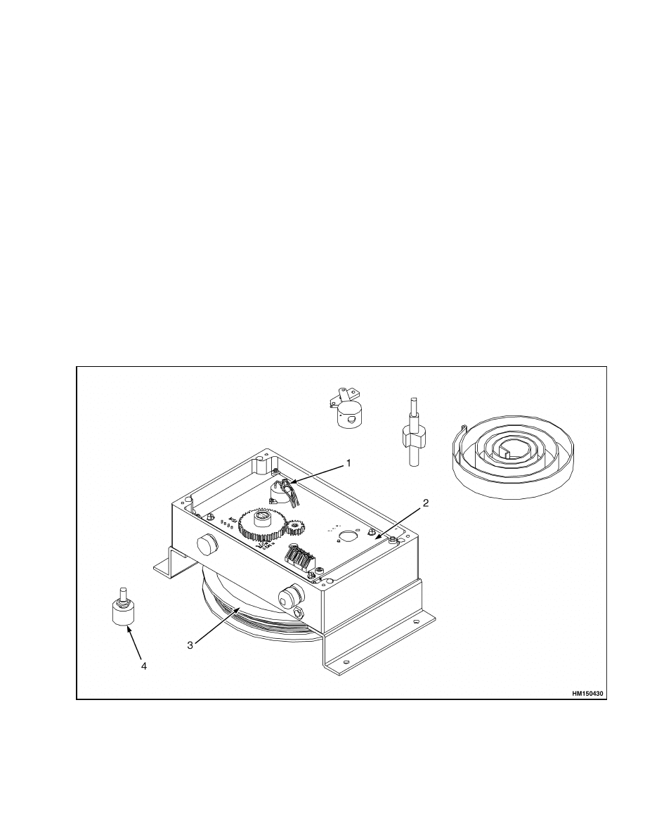
The compacted integrated transducer is assembled
on the left outside of the outer boom and contains
the components as shown in Figure 3. A drum cable
servo-winder is assembled on which a cable is wound.
The other side of the cable is connected to the inner
boom. A potentiometric sensor is assembled in the
servo-winder and measures the drum rotation and
therefore the boom extension. A second potentiomet-
ric sensor is positioned on the circuit board and mea-
sures the absolute angle of the boom to the horizontal
reference. These potentiometric sensors are used by
the main computer to measure the angle/extension of
the boom.
PRESSURE TRANSDUCERS
NOTE: The pressure reducers are exchangeable.
When a fault code occurs, it’s possible to swab
the pressure reducers and check if the fault code
changes.
If the fault code changes, the pressure
transducer must be replaced. When the fault code
remains, the problem must be found somewhere
else.
The pressure transducers detect the pressure on the
boom lifting cylinders. Typically, the two sensors are
required for measuring the differential pressure on
the main cylinders. From these values the weight
is calculated. These sensing devices detect the pres-
sure by an element, which transforms the detected
pressure into a direct voltage proportional to the
pressure. The on-board amplifier is included in the
sensors itself.
Any possible replacement of these
elements is very easy because of their compatibility.
1.
POTENTIOMETRIC SENSOR (ANGLE)
2.
CIRCUIT BOARD
3.
SERVO-WINDER
4.
POTENTIOMETRIC SENSOR (EXTENSION)
Figure 3. Compact Integrated Transducer
3

Operation (Compact Display Panel)
1900 SRM 1213
Operation (Compact Display Panel)
DISPLAY
NOTE: See the Operators Manual for the explana-
tion of the display functions of the 3B6 Load Limiter
System.
The following table shows the main screen which is
typically displayed during normal operation. The up-
per line shows the Bar, which in semi-graphic mode,
gives the percentage load with respect to the maxi-
mum load divided into green, yellow, and red areas.
WWW.W
RR.R
MMM.M
The lower line shows:
WWW.W
: Current weight.
RR.R
: Current radius. Measurement of
the projection from the fifth wheel
center to the point of application to
the load.
MMM.M
: Maximum load allowed in the
current machine position.
By pressing the ENTER button, the display shows
for a few seconds the measure of boom length, the
height, and the angle. See the following table. The
measure unit is in accordance with the selected unit.
LLL.L
HH.H
AAA.A
This line shows:
LLL.L
:
Boom length.
HH.H
:
Height from the ground.
AAA.A
:
Angle in degrees.
The following warning message will be shown on the
display if the specific condition occurs.
•
MAX CAPACITY
•
NEGATIVE LOAD
•
MIN. RADIUS
•
MAX. EXTENDED
•
MIN. RETRACTED
•
MAX. ANGLE
•
MIN. ANGLE
DISPLAYS FOR THE OPERATOR
The following indicates the pages that show the most
important machine data and can be displayed in se-
quence by pressing the ENTER button.
Page 1
P100
A60
W5.0
L20.3
M5.0
R15.1
•
P
:
Differential Pressure [BAR]
•
W
:
Current Weight [T]
•
M
:
Maximum load allowed in the current
position [T]
•
A
:
Current angle in degrees
•
L
:
Current extension [m or ft]
•
R
:
Radius [m or ft]
Page 2
P100
P 0
L:50
l 0
H:40
h 0
•
PL
:
Differential pressure lifting cylinder
[BAR]
•
PL
:
Pressure piston side lifting cylinder
•
PH
:
Pressure rod side lifting cylinder
•
A
:
Current angle in degrees
•
l
:
Current extension [m or ft]
•
W
:
Current weight [T]
•
H
:
Pressure rod side compensation
cylinder
4

1900 SRM 1213
Replace and Adjust
Page 3
0
2
XXXX
XXXX
1
3
XXXX
XXXX
•
0
:
Pressure transducer piston side lifting
cylinder [bit]
•
1
:
Pressure transducer rod side lifting
cylinder
•
2
:
Transducer angle [bit]
•
3
:
Transducer extension [bit]
Page 4
4
6
XXXX
XXXX
5
7
XXXX
XXXX
Other analog inputs (not used in this application)
•
4
:
Analog input #4
•
5
:
Analog input #5
•
6
:
Analog input #6
•
7
:
Analog input #7
Page 5
l
01234567890123
*- - - - - - - - - - - -
Digital inputs. The symbol "*" indicates active input
while "-" indicates inactive input.
•
0
:
Cabin in retract position
Others not used.
Page 6
O
01234567890123
- - - - * *- - - - - - -
Digital outputs. The symbol "*" indicates active out-
put while "-" indicates inactive output.
•
4
:
Cut off command
•
5
:
Cut off command for minimum radius
Others not used.
Replace and Adjust
GENERAL
NOTE: These instructions must be followed com-
pletely or the system may have to be calibrated by a
HYSTER COMPANY technician.
NOTE: Replace and adjust procedures must be fol-
lowed before attempting to replace a component or
make an adjustment. If a component replacement is
necessary, order the component from your HYSTER
COMPANY authorized dealer before removing the
component. Include truck model and serial number
when ordering to ensure proper operation over the
range of the original system installation.
This section provides step-by-step procedures to re-
place the components of the system and to perform
the necessary adjustments on these components.
MAIN UNIT
Remove
NOTE: The main unit is mounted at the right-hand
side of the operators cab floor.
1.
Remove the four screws from the top cover.
2.
Remove the top cover.
3.
Disconnect all electrical cables from the main
unit and tag all connector wires to aid in instal-
lation.
4.
Remove the four screws inside the main unit that
holds the unit to the cab.
5

Replace and Adjust
1900 SRM 1213
Install
1.
Place the main unit at the cab floor and install
the four inside screws of the unit.
2.
Connect all electrical cables to the main unit as
tagged during removal.
3.
Install the top cover with the four screws.
LOAD LIMITER SYSTEM DISPLAY
Remove
NOTE: The load limiter system display is mounted on
a bracket in the operators cab on top of the operators
instrument panel. It consists of a display panel and
indicator buttons used to monitor the load.
1.
Remove the connector from the rear side of the
Load Limiter System.
2.
Remove the two black plastic knobs from the
sides of the system.
3.
Remove the system from the mounting bracket.
Install
1.
Install the Load Limiter System in the mounting
bracket.
2.
Install the two black plastic knobs on the sides of
the system and tighten.
3.
Install the connector at the rear side of the sys-
tem.
COMPACT INTEGRATED TRANSDUCER
Remove
NOTE:
The
compact
integrated
transducer
is
mounted at the left outer boom, and is attached
to the inner boom with a cable.
NOTE: The cable length must remain the same or
calibration must be done by qualified personnel.
1.
Remove the four screws from the top cover.
2.
Remove the top cover.
3.
Disconnect the cable from the inner boom.
4.
Disconnect all electrical cables from the compact
integrated transducer and tag all connector wires
to aid in the installation.
5.
Remove the four screws which hold the compact
integrated transducer at the outer boom.
Install
1.
Attach the compact integrated transducer to the
outer boom.
2.
Connect all electrical cables to the compact inte-
grated transducer as tagged during removal.
3.
Connect the cable to the inner boom.
4.
Install the top cover with the four screws.
5.
Check the correct cable length as follows:
a. Switch ON the 3B6 load limiter system dis-
play.
******
0.0
8.8
4
6.0
b. Press "ENTER" 4 times until page 4 appears
with the sensor value information.
O XXXX
1 XXXX
2 XXXX
3 XXXX
c.
Verify the boom is positioned at 0 degrees.
Check if value 2 is between 500 and 520,
and that the value goes up when the boom
is lifted.
d. Verify the cable length is at least 1 m (3.3 ft)
when the boom is positioned at 0 degrees.
Connect the cable when value 3 is between
30 and 60.
PRESSURE TRANSDUCERS
Remove
NOTE: The pressure transducers are mounted on the
bottom of the right lift cylinder.
1.
Place a drip pan underneath the pressure trans-
ducers to catch any fluid spilled when the pres-
sure transducers are removed.
2.
Remove the screw at the topside of the electrical
connector.
3.
Remove the electrical connector from the pres-
sure transducer.
6

1900 SRM 1213
Replace and Adjust
4.
Remove the pressure transducer and adapter
from the hydraulic block.
5.
Remove the adapter from the pressure trans-
ducer.
6.
Place end caps on the disconnected hydraulic
lines.
Install
1.
Place a drip pan underneath the pressure trans-
ducers to catch any fluid spilled when the pres-
sure transducers are installed.
2.
Remove the end caps from the hydraulic lines.
3.
Install the adapter onto the hydraulic block.
4.
Install the pressure transducer onto the adapter.
5.
Install the electrical connector to the pressure
transducer.
6.
Tighten the screw at the topside of the electrical
connector.
ANGLE POTENTIOMETER
Boom Angle Calibration
NOTE: Use this procedure to verify that the actual
boom angle agrees with the angle shown on the Load
Sensing System display.
1.
Select the operator display with the code typed
and press the "INDEX" button.
*****
WWW.W
RR.R
MMM.M
2.
Select command 12 Angle Transd. Confirm and
press the "ENTER" button.
AAA
LLL
WWW
12 Angle Transd
3.
Lower the boom to a 0-degree angle. Use an angle
protractor to verify the angle of the boom. Check
if the value “Angle Min” is between 500 and 520.
Adjust if necessary.
A: 00.0
t500
Angle Min
0.0
4.
When the value “Angle Min” is correct, select the
“SET MIN” screen and press the “ENTER” but-
ton to save this value.
A: 00.0
t500
SET MIN
0.0
5.
Raise the boom to an angle of 60 degrees. Use an
angle protractor to verify the actual angle. Check
if the value “Angle Max” is between 680 and 690.
Adjust if necessary.
A: 60.0
t690
Angle Max
60
6.
When the value “Angle Max” is correct, select the
“SET MAX” screen and press the “ENTER” but-
ton to save this value.
A: 60.0
t690
SET MAX
60
LENGTH POTENTIOMETER
Boom Length Calibration
NOTE: A variation of approximately ±1 m (±3 ft)
would indicate one wrap of cable was removed or
added to the cable reel.
1.
Select the operator display with the code typed
and press the “INDEX” button.
*****
WWW.W
RR.R
MMM.M
2.
Select command “13 Boom Transd.” Confirm and
press the “ENTER” button.
AAA
LLL
WWW
13 Boom Transd
3.
Fully retract the main boom. Check if the value
“Boom min” is between 20 and 60. Adjust, if nec-
essary.
L: 8.8
t50
Boom Min
8.82
7

Troubleshooting
1900 SRM 1213
4.
When the value “Boom Min” is correct, select the
“SET MIN” screen and press the “ENTER” but-
ton to save this value.
L: 8.8
t50
SET MIN
5.
Fully extend the main boom. Check if the value
“Boom Max” is between 600 and 610. Adjust, if
necessary.
L: 15.8
t600
Boom Max
15.80
6.
When the value “Boom Max” is correct, select the
“SET MAX” screen and press the “ENTER” but-
ton to save this value.
L: 15.8
t600
Boom Max
Diagnostics
The limiter is equipped with a diagnostic part, which registers each failure of external transducers or internal
damages. When damage is registered, the limiter will put itself in a safety condition by blocking maneuvers
and, at the same time, an alarm message will be displayed.
Printer Options
See the Operators Manual for the printer options of the 3B6 Load Limiter System.
Troubleshooting
See the Operators Manual for the troubleshooting of the 3B6 Load Limiter System.
8


TECHNICAL PUBLICATIONS
1900 SRM 1213
3/05 Printed in United Kingdom
Document Outline
- toc
Wyszukiwarka
Podobne podstrony:
897956 1900SRM0642 (03 2005) UK EN
897953 1600SRM0639 (03 2005) UK EN
910091 1900SRM0097 (08 2005) UK EN
897963 4500SRM0649 (03 2005) UK EN
1573930 0600SRM1172 (03 2005) UK EN
1586985 2200SRM1178 (03 2005) UK EN
897345 1400SRM0413 (03 2005) UK EN
1531815 1800SRM1040 (03 2005) UK EN
1466217 1900SRM0743 (06 2005) UK EN
899782 2000SRM0077 (03 2005) UK EN
897875 8000SRM0616 (03 2005) UK EN
897961 2200SRM0647 (03 2005) UK EN
1597925 0700SRM1211 (03 2005) UK EN
1586982 0100SRM1177 (03 2005) UK EN
1466169 4000SRM0741 (03 2005) UK EN
1495208 8000SRM0949 (03 2005) UK EN
więcej podobnych podstron