CAPACITIES AND
SPECIFICATIONS
RS45-27CH, RS45-30CH, RS45-27IH, RS46-33CH,
RS46-30IH, RS46-36CH, RS46-33IH First Used
on 1529, 1533 and Up [A222]
PART NO. 1495208
8000 SRM 949

SAFETY PRECAUTIONS
MAINTENANCE AND REPAIR
• When lifting parts or assemblies, make sure all slings, chains, or cables are correctly
fastened, and that the load being lifted is balanced. Make sure the crane, cables, and
chains have the capacity to support the weight of the load.
• Do not lift heavy parts by hand, use a lifting mechanism.
• Wear safety glasses.
• DISCONNECT THE BATTERY CONNECTOR before doing any maintenance or repair
on electric lift trucks. Disconnect the battery ground cable on internal combustion lift
trucks.
• Always use correct blocks to prevent the unit from rolling or falling. See HOW TO PUT
THE LIFT TRUCK ON BLOCKS in the Operating Manual or the Periodic Mainte-
nance section.
• Keep the unit clean and the working area clean and orderly.
• Use the correct tools for the job.
• Keep the tools clean and in good condition.
• Always use HYSTER APPROVED parts when making repairs. Replacement parts
must meet or exceed the specifications of the original equipment manufacturer.
• Make sure all nuts, bolts, snap rings, and other fastening devices are removed before
using force to remove parts.
• Always fasten a DO NOT OPERATE tag to the controls of the unit when making repairs,
or if the unit needs repairs.
• Be sure to follow the WARNING and CAUTION notes in the instructions.
• Gasoline, Liquid Petroleum Gas (LPG), Compressed Natural Gas (CNG), and Diesel fuel
are flammable. Be sure to follow the necessary safety precautions when handling these
fuels and when working on these fuel systems.
• Batteries generate flammable gas when they are being charged. Keep fire and sparks
away from the area. Make sure the area is well ventilated.
NOTE: The following symbols and words indicate safety information in this
manual:
WARNING
Indicates a condition that can cause immediate death or injury!
CAUTION
Indicates a condition that can cause property damage!

Capacities and Specifications
Table of Contents
TABLE OF CONTENTS
Counterweight Weights .....................................................................................................................................
Container Attachment Weights.........................................................................................................................
Vehicle Weights ..................................................................................................................................................
Capacities ...........................................................................................................................................................
Electrical System ...............................................................................................................................................
Engine Specifications.........................................................................................................................................
Tire Sizes ............................................................................................................................................................
Hydraulic System Specifications.......................................................................................................................
Torque Specifications .........................................................................................................................................
Control Valves ................................................................................................................................................
Electrical System ...........................................................................................................................................
Counterweight (Cast) ....................................................................................................................................
Counterweight (Fabricated) ..........................................................................................................................
Counterweight (Slab).....................................................................................................................................
Drive Axle ......................................................................................................................................................
Drive Axle Rod ...............................................................................................................................................
Drive Shaft .....................................................................................................................................................
Service Brakes ...............................................................................................................................................
Wheel Bearing Adjusting Nut.......................................................................................................................
Differential.....................................................................................................................................................
Transmission..................................................................................................................................................
Torque Converter ...........................................................................................................................................
Steering ..........................................................................................................................................................
Wheel Nuts.....................................................................................................................................................
20- to 40-ft Attachment .................................................................................................................................
Container Spreader Without Powered Pile Slope Lifting Capacities..............................................................
Container Spreader With Powered Pile Slope Lifting Capacities ...................................................................
Intermodal Spreader Lifting Capacities ...........................................................................................................
This section is for the following models:
RS45-27CH, RS45-30CH, RS45-27IH, RS46-33CH, RS46-30IH, RS46-36CH,
RS46-33IH First Used on 1529, 1533 and Up [A222]
©2005 HYSTER COMPANY
i

"THE
QUALITY
KEEPERS"
HYSTER
APPROVED
PARTS

8000 SRM 949
Container Attachment Weights
Counterweight Weights
Table 1. Fabricated
Unit
Main Counterweight
Slab Counterweight
RS45-27CH
14,400 to 14,382 kg
(31,747 to 31,707 lb)
N/A
RS45-30CH, RS45-27IH,
RS46-33CH, RS46-30IH
17,300 to 17,819 kg
(38,140 to 39,284 lb)
N/A
RS46-36CH, RS46-33IH
19,300 to 19,879 kg
(42,549 to 43,826 lb)
1400 to 1420 kg
(3086 to 3131 lb)
Table 2.
Cast
Unit
Main Counterweight
Rear Counterweight
RS45-27CH, RS45-30CH,
RS45-27IH
12,870 to 13,130 kg
(28,374 to 28,947 lb)
N/A
RS46-33CH, RS46-30IH
12,870 to 13,130 kg
(28,374 to 28,947 lb)
3317 to 3383 kg
(7313 to 7458 lb)
RS46-36CH, RS46-33IH
12,870 to 13,130 kg
(28,374 to 28,947 lb)
6138 to 6262 kg
(13,532 to 13,805 lb)
Container Attachment Weights
Table 3. Attachment With 1 Dampening Cylinder
Attachment
Without Power Pile Slope
With Power Pile Slope
Extendable
9900 kg (21,826 lb)
10,700 kg (23,590 lb)
Intermodal
N/A
13,800 kg (30,424 lb)
Table 4. Attachment With 2 Dampening Cylinders
Attachment
Without Power Pile Slope
With Power Pile Slope
Extendable
9200 kg (20,283 lb)
10,000 kg (22,046 lb)
Intermodal
N/A
13,100 kg (28,881 lb)
1

Electrical System
8000 SRM 949
Vehicle Weights
Unit
Without Power Pile Slope*
With Power Pile Slope*
RS45-27CH
67,274 kg (148,314 lb)
68,644 kg (151,334 lb)
RS45-30CH
70,176 kg (154,712 lb)
71,517 kg (157,668 lb)
RS46-33CH
75,173 kg (165,728 lb)
76,516 kg (168,689 lb)
RS46-36CH
78,053 kg (172,077 lb)
79,493 kg (175,252 lb)
RS45-27IH
N/A
75,034 kg (165,422 lb)
RS46-30IH
N/A
79,637 kg (175,570 lb)
RS46-33IH
N/A
82,597 kg (182,095 lb)
*Total vehicle weight, no load.
Capacities
Item
Quantity
Engine Oil
37 liter (39 qt)
Cooling System
40 liter (42 qt)
Hydraulic Tank
850 liter (224 gal)
Transmission
45 liter (46 qt)
Drive Axle and Differential
65 liter (69 qt)
Fuel Tank
500 liter (106 gal)
Electrical System
24 Volt, Negative Ground
Alternator Output
70 Amps
2

8000 SRM 949
Tire Sizes
Engine Specifications
Specification
Item
Tier 1
Tier 2
Type
Cummins M11
Cummins QSM11
Number of Cylinders
6
6
Firing Order
1-5-3-6-2-4
1-5-3-6-2-4
Bore
125 mm (4.92 in.)
125 mm (4.92 in.)
Stroke
147 mm (5.787 in.)
147 mm (5.787 in.)
Displacement
10.8 liter (661 in.
3
)
10.8 liter (661 in.
3
)
Oil Pressure (minimum at
idle)
70 kPa (10.15 psi)
70 kPa (10.15 psi)
Governed Speed
2286 rpm
2100 rpm
Idle Speed
775-825 rpm
750-800 rpm
Stall Speed
1950-2050 rpm
1900-2000 rpm
Valve Clearance (Cold)
Intake
0.36 mm (0.014 in.)
0.36 mm (0.014 in.)
Exhaust
0.68 mm (0.026 in.)
0.68 mm (0.026 in.)
Weight
940 kg (2072 lb)
940 kg (2072 lb)
Tire Sizes
Model
Drive
Steer
RS45-27CH
18.00 × 25 - 36 ply
18.00 × 25 - 36 ply
RS45-30CH
18.00 × 25 - 40 ply
18.00 × 25 - 40 ply
RS46-33CH
18.00 × 33 - 36 ply
18.00 × 33 - 36 ply
RS46-36CH
18.00 × 33 - 36 ply
18.00 × 33 - 36 ply
RS45-27IH
18.00 × 25 - 40 ply
18.00 × 25 - 40 ply
RS46-30IH
18.00 × 33 - 36 ply
18.00 × 33 - 36 ply
RS46-33IH
18.00 × 33 - 36 ply
18.00 × 33 - 36 ply
3

Hydraulic System Specifications
8000 SRM 949
Hydraulic System Specifications
Item
Specification
Hydraulic Pumps Output @ 2100 rpm (Governed speed-no load)
Main Valve 1 [92 ml (5.6 in.
3
) per revolution]
193.2 liter/min (51 gal/min)
Main Valve 2 [92 ml (5.6 in.
3
) per revolution]
193.2 liter/min (51 gal/min)
Brake Pump [50 ml (3.0 in.
3
) per revolution]
105 liter/min (27.73 gal/min)
Attachment Pump [58.7 ml (3.58 in.
3
) per revolution]
123.27 liter/min (32.56 gal/min)
Relief Valve (approximate operating pressure)
Main Valve 3
32 MPa (4641 psi)
Main Valve 4
32 MPa (4641 psi)
Charge Valve
15.86 to 18.96 MPa (2300 to 2750 psi)
Pilot Circuit
5.0 MPa (725 psi)
Boom Derricking
30.0 MPa (4351 psi)
Boom Telescoping Out
30.0 MPa (4351 psi)
Boom Telescoping In
30.0 MPa (4351 psi)
Container Attachment
16.0 MPa (2321 psi)
Parking Brake Circuit
17.0 MPa (2366 psi)
Steering Circuit
17.2 MPa (2495 psi)
Power Pile Slope Circuit
23.5 MPa (3408 psi)
Dampening Circuit
10 MPa (1450 psi)
Thermostatic Bypass Pressure
345 kPa (50 psi)
Twist Lock Circuit
8.3 MPa (1204 psi)
Sideshift Circuit
12.4 MPa (1798 psi)
Extend/Retract Circuit
8.6 MPa (1247 psi)
Check Port Pressures
M1 - Boom Out
28 MPa (4061 psi)
M2 - Pilot Pressure
5.0 MPa (725 psi)
M3 - Charge Valve
15.86 MPa (2300 psi)
M4 - Park Brake
16.0 MPa (2321 psi)
M5 - Steering Circuit
18.5 MPa (2683 psi)
M6 - Boom Up
28 MPa (4061 psi)
M7 - Boom Down
28 MPa (4061 psi)
M8 - Spreader Pressure
16.5 MPa (2393 psi)
M9 - Boom In
28 MPa (4061 psi)
M10 - Sliding Cab
2 MPa (290 psi)
4
8000 SRM 949
Torque Specifications
Item
Specification
Hydraulic Oil Filters
Bypass Pressure
69 to103 kPa (10 to 14.94 psi)
Transmission Sump Oil Filter
Bypass Pressure
172 kPa (10 to 24.94 psi)
Brake System Oil Filter
Bypass Pressure
15 kPa (2.18 psi)
Torque Specifications
CONTROL VALVES
Main Control Valves (Section Fastening Bolts)
80 N•m (59 lbf ft)
Accumulator Charge Valve Adjustment Screw
24 to 30 N•m (18 to 22 lbf ft)
Accumulator Charge Valve Adjustment Nut
54 to 61 N•m (40 to 45 lbf ft)
Accumulator Charge Valve Plug
34 to 47 N•m (25 to 35 lbf ft)
Hydraulic Pumps Capscrews
90 N•m (66 lbf ft)
ELECTRICAL SYSTEM
Alternator Shaft Nut
95 to 108 N•m (70 to 80 lbf ft)
Alternator Mount Bolt
81 to 95 N•m (60 to 70 lbf ft)
Alternator Battery (B+) Terminal
9 to 13.6 N•m (80 to 120 lbf in)
Alternator Indicator (I) Terminal
1.7 to 2.8 N•m (15 to 25 lbf in)
Alternator Ground (B-) Terminal
5.6 to 6.8 N•m (50 to 60 lbf in)
COUNTERWEIGHT (CAST)
Main Counterweight Top Tie Rod Weldments
700 N•m (516 lbf ft)
Main Counterweight Rear Tie Rod Weldments
1500 N•m (1106 lbf ft)
Rear Counterweight Tie Rod Weldments
1500 N•m (1106 lbf ft)
COUNTERWEIGHT (FABRICATED)
Main Counterweight Top Tie Rod Weldments
1500 N•m (1106 lbf ft)
Main Counterweight Rear Tie Rod Weldments
1500 N•m (1106 lbf ft)
COUNTERWEIGHT (SLAB)
Main Counterweight Mounting Capscrews
600 N•m (443 lbf ft)
DRIVE AXLE
Mounting Bolts
1150 to 1250 N•m (848 to 922 lbf ft)
DRIVE AXLE ROD
Contra Nuts
5 to 25 N•m (4 to 18 lbf ft)
Lock Nuts
5 to 25 N•m (4 to 18 lbf ft)
DRIVE SHAFT
Universal Joint Capscrew
117 to 127 N•m (86 to 94 lbf ft)
Universal Joint Hex Bolt
130 to 140 N•m (96 to 103 lbf ft)
5

Torque Specifications
8000 SRM 949
SERVICE BRAKES
Hydraulic Bleeder Screw
20 to 27 N•m (15 to 20 lbf ft)
Minimum Torque For Coolant Fill Level
Plug (Sump Cooling Only)
47 N•m (35 lbf ft)
Coolant Input Port Plug
81 to 102 N•m (60 to 75 lbf ft)
Coolant Output Port Plug
81 to 102 N•m (60 to 75 lbf ft)
WHEEL BEARING ADJUSTING NUT
PRC-5324 to 7314 (Initial Value)
813 N•m (600 lbf ft)
PRC-5324 to 7314 (Final Value)
678 N•m (500 lbf ft)
PRC-7534 (Initial Value)
949 N•m (700 lbf ft)
PRC-7534 (Final Value)
746 N•m (550 lbf ft)
DIFFERENTIAL
See the section Differential 1400 SRM 46
TRANSMISSION
See the section Four-Speed Powershift Trans-
mission, Repair (HR 36000) 1300 SRM 635
TORQUE CONVERTER
See the section Four-Speed Powershift Trans-
mission, Repair (HR 36000) 1300 SRM 635
STEERING
Steering Wheel Nut
35 to 45 N•m (26 to 33 lbf ft)
Steering Control Unit Block
40 N•m (30 lbf ft)
Steering Column
47 N•m (35 lbf ft)
Steering Cylinder Mounting Bolts
1200 to 1400 N•m (885 to 1033 lbf ft)
Tie Rod Nuts
320 N•m (236 lbf ft)
Spindle bearing cup for lower pivot
bearings (Initial Value) (adjust to zero
clearance for final value)
47 N•m (35 lbf ft)
Inner spindle wheel nut (Initial Value) (Adjust
to finger tight for final value)
203 N•m (150 lbf ft)
Outer Spindle Wheel Nut
135 to 271 N•m (100 to 200 lbf ft)
WHEEL NUTS
Drive Wheels
405 to 440 N•m (299 to 325 lbf ft)
Steer Wheels
128 to 147 N•m (94 to 108 lbf ft)
20- TO 40-FT ATTACHMENT
Hose Clamps
28 N•m (21 lbf ft)
6
8000 SRM 949
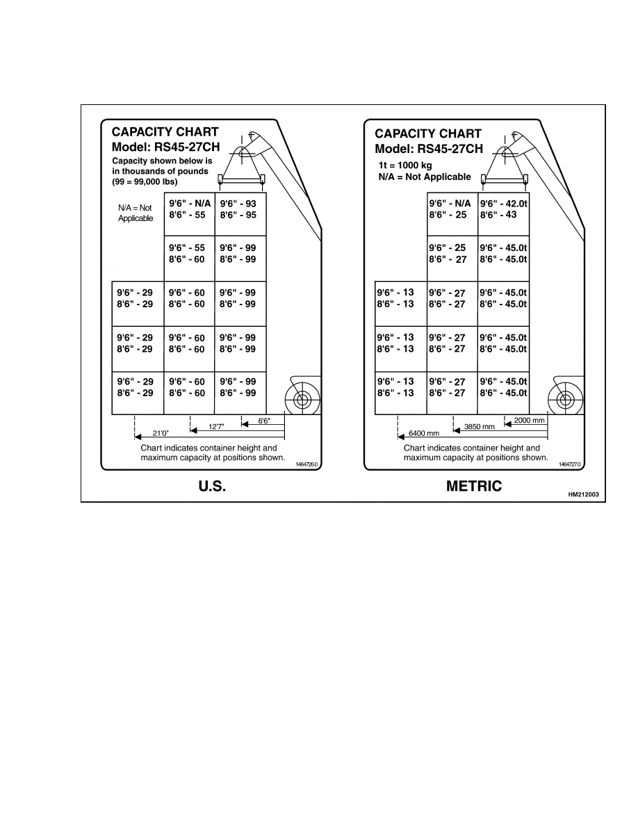
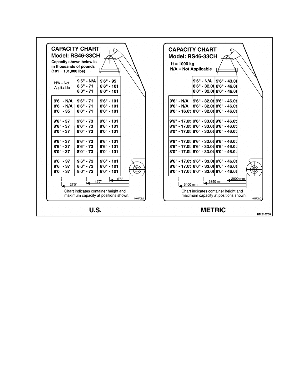
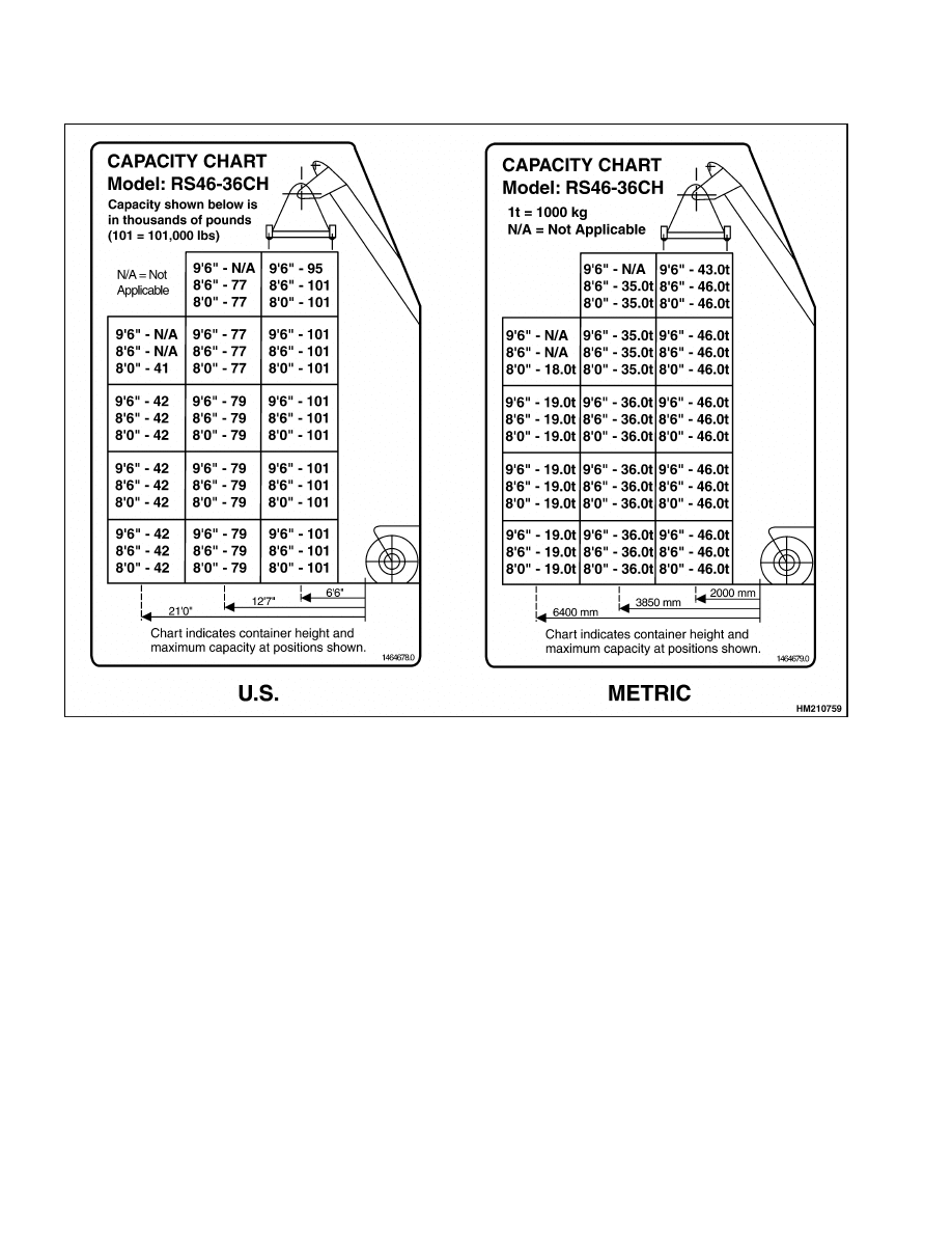
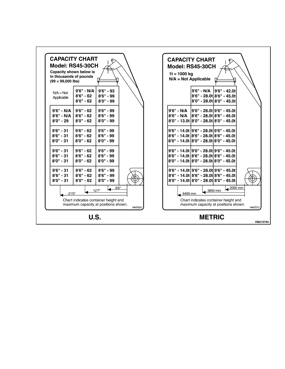
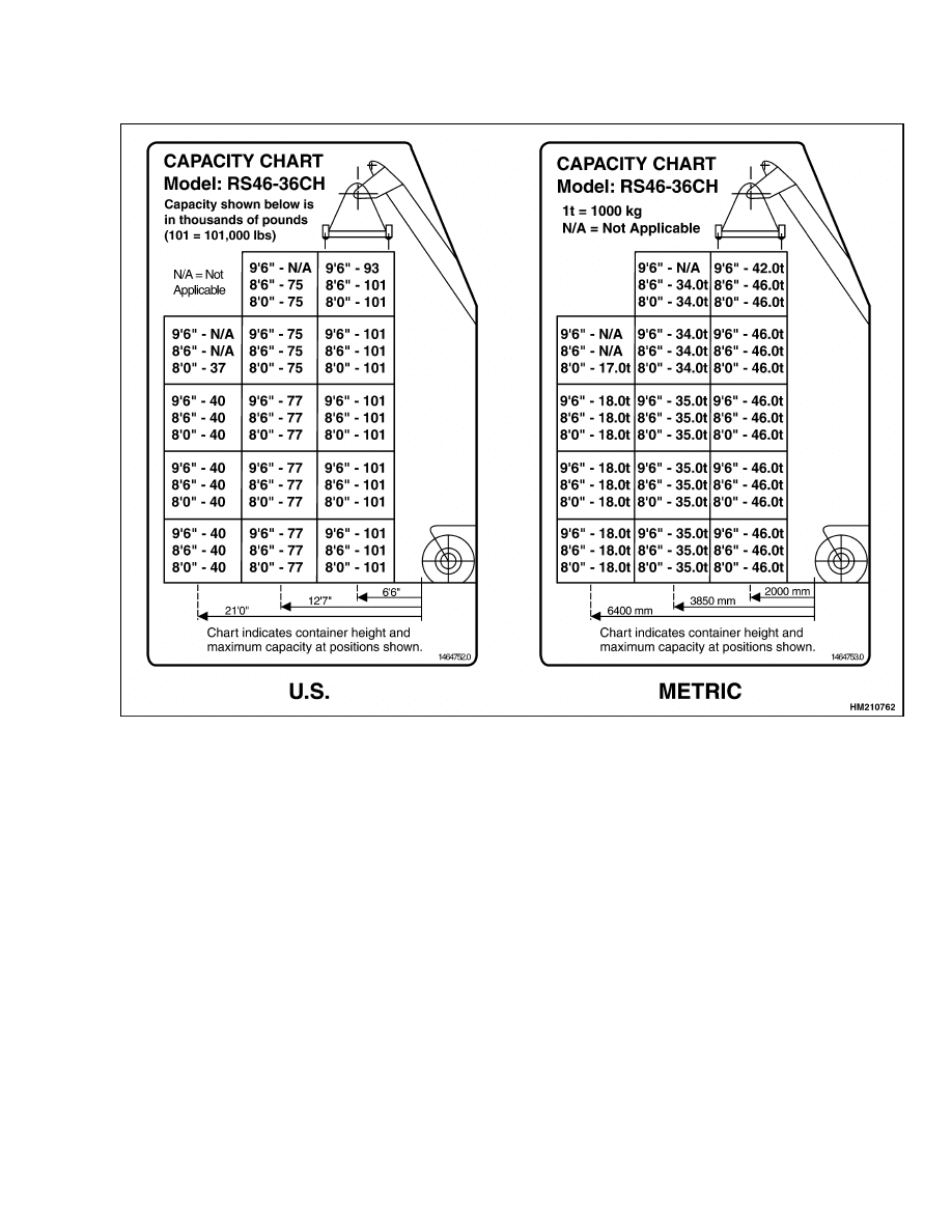
Container Spreader Without Powered Pile Slope Lifting Capacities
Container Spreader Without Powered Pile Slope Lifting Capacities
7
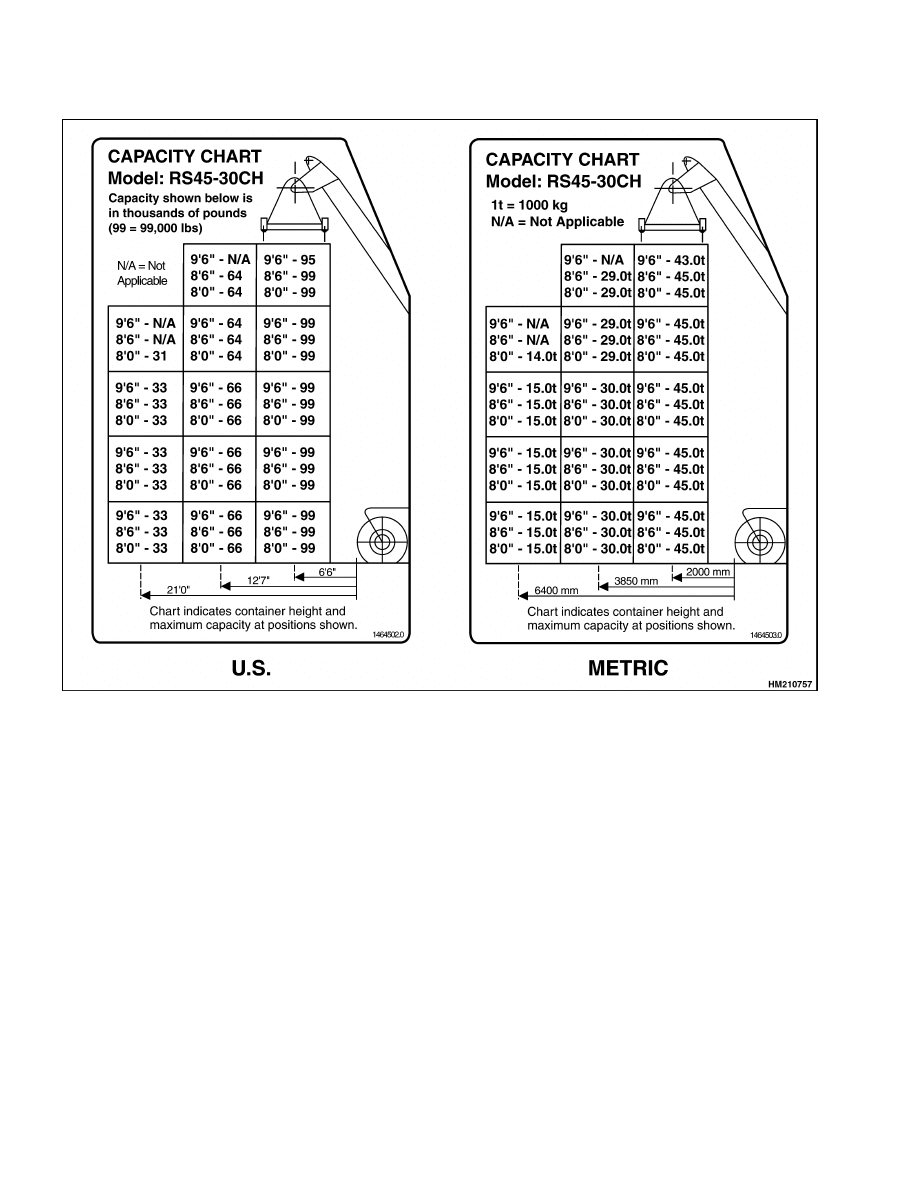
Container Spreader Without Powered Pile Slope Lifting Capacities
8000 SRM 949
8
8000 SRM 949
Container Spreader Without Powered Pile Slope Lifting Capacities
9
Container Spreader Without Powered Pile Slope Lifting Capacities
8000 SRM 949
10
8000 SRM 949
Container Spreader With Powered Pile Slope Lifting Capacities
Container Spreader With Powered Pile Slope Lifting Capacities
11

Container Spreader With Powered Pile Slope Lifting Capacities
8000 SRM 949
12
8000 SRM 949
Container Spreader With Powered Pile Slope Lifting Capacities
13
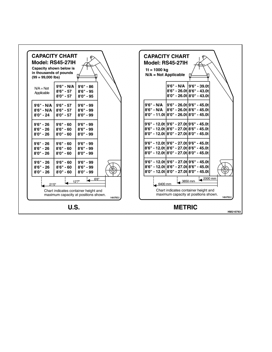
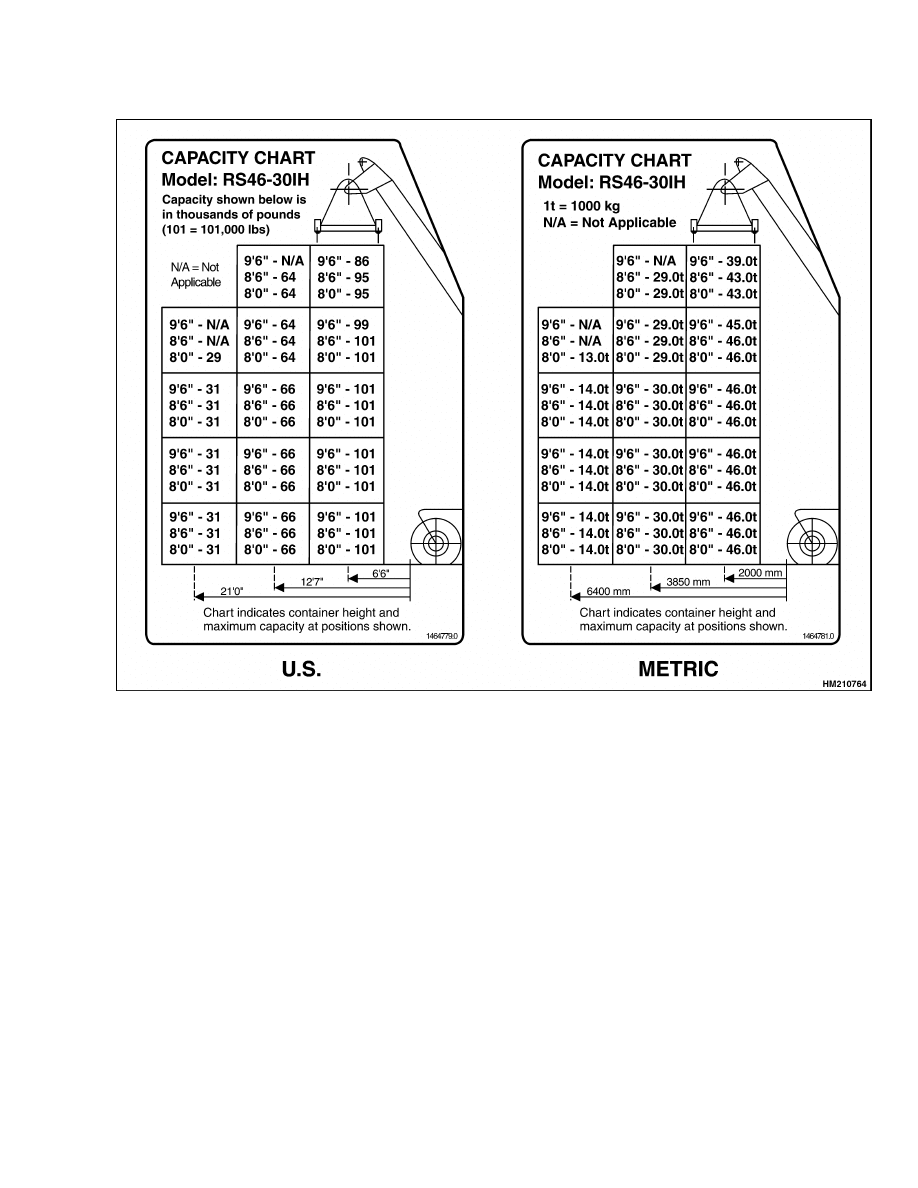
Intermodal Spreader Lifting Capacities
8000 SRM 949
Intermodal Spreader Lifting Capacities
14
8000 SRM 949
Intermodal Spreader Lifting Capacities
15

Intermodal Spreader Lifting Capacities
8000 SRM 949
16


TECHNICAL PUBLICATIONS
8000 SRM 949
3/05 (12/00) Printed in United Kingdom
Document Outline
- toc
- Capacities and Specifications
- Safety Precautions Maintenance and Repair
- Counterweight Weights
- Container Attachment Weights
- Vehicle Weights
- Capacities
- Electrical System
- Engine Specifications
- Tire Sizes
- Hydraulic System Specifications
- Torque Specifications
- Container Spreader Without Powered Pile Slope Lifting Capacities
- Container Spreader With Powered Pile Slope Lifting Capacities
- Intermodal Spreader Lifting Capacities
- tables
Wyszukiwarka
Podobne podstrony:
897875 8000SRM0616 (03 2005) UK EN
1458783 8000SRM0592 (03 2005) UK EN
1510478 8000SRM0988 (06 2005) UK EN
897953 1600SRM0639 (03 2005) UK EN
1598459 1900SRM1213 (03 2005) UK EN
897956 1900SRM0642 (03 2005) UK EN
897457 8000SRM0488 (03 1992) UK EN
897963 4500SRM0649 (03 2005) UK EN
1566279 8000SRM1155 (02 2005) UK EN
1573930 0600SRM1172 (03 2005) UK EN
1586985 2200SRM1178 (03 2005) UK EN
897345 1400SRM0413 (03 2005) UK EN
1531815 1800SRM1040 (03 2005) UK EN
899782 2000SRM0077 (03 2005) UK EN
1580526 8000SRM1151 (05 2005) UK EN
więcej podobnych podstron