FRAME
E3.50-5.50XL, E4.50XLS
(E70-120Z, E100ZS) [D098]
PART NO. 1596602
100 SRM 1200

SAFETY PRECAUTIONS
MAINTENANCE AND REPAIR
• When lifting parts or assemblies, make sure all slings, chains, or cables are correctly
fastened, and that the load being lifted is balanced. Make sure the crane, cables, and
chains have the capacity to support the weight of the load.
• Do not lift heavy parts by hand, use a lifting mechanism.
• Wear safety glasses.
• DISCONNECT THE BATTERY CONNECTOR before doing any maintenance or repair
on electric lift trucks. Disconnect the battery ground cable on internal combustion lift
trucks.
• Always use correct blocks to prevent the unit from rolling or falling. See HOW TO PUT
THE LIFT TRUCK ON BLOCKS in the Operating Manual or the Periodic Mainte-
nance section.
• Keep the unit clean and the working area clean and orderly.
• Use the correct tools for the job.
• Keep the tools clean and in good condition.
• Always use HYSTER APPROVED parts when making repairs. Replacement parts
must meet or exceed the specifications of the original equipment manufacturer.
• Make sure all nuts, bolts, snap rings, and other fastening devices are removed before
using force to remove parts.
• Always fasten a DO NOT OPERATE tag to the controls of the unit when making repairs,
or if the unit needs repairs.
• Be sure to follow the WARNING and CAUTION notes in the instructions.
• Gasoline, Liquid Petroleum Gas (LPG), Compressed Natural Gas (CNG), and Diesel fuel
are flammable. Be sure to follow the necessary safety precautions when handling these
fuels and when working on these fuel systems.
• Batteries generate flammable gas when they are being charged. Keep fire and sparks
away from the area. Make sure the area is well ventilated.
NOTE: The following symbols and words indicate safety information in this
manual:
WARNING
Indicates a condition that can cause immediate death or injury!
CAUTION
Indicates a condition that can cause property damage!

Frame
Table of Contents
TABLE OF CONTENTS
General ...............................................................................................................................................................
Description .........................................................................................................................................................
Overhead Guard Repair ....................................................................................................................................
Remove ...........................................................................................................................................................
Install .............................................................................................................................................................
Battery and Operator Restraint, Hood and Seat Brake Repair ......................................................................
Battery Restraint and Hood Repair..............................................................................................................
Operator Restraint Repair ............................................................................................................................
Seat Brake Repair .........................................................................................................................................
Counterweight Repair .......................................................................................................................................
Remove ...........................................................................................................................................................
Install .............................................................................................................................................................
Traction Motor Repair .......................................................................................................................................
Remove ...........................................................................................................................................................
Install .............................................................................................................................................................
Hydraulic Tank Repair ......................................................................................................................................
Inspect ............................................................................................................................................................
Small Leaks, Repair ......................................................................................................................................
Large Leaks, Repair ......................................................................................................................................
Clean ..............................................................................................................................................................
Steam Method............................................................................................................................................
Chemical Solution Method........................................................................................................................
Additional Preparations For Repair .............................................................................................................
Safety Label Replacement .................................................................................................................................
Battery Specifications........................................................................................................................................
This section is for the following models:
E3.50-5.50XL, E4.50XLS (E70-120Z, E100ZS) [D098]
©2005 HYSTER COMPANY
i

"THE
QUALITY
KEEPERS"
HYSTER
APPROVED
PARTS

100 SRM 1200
Description
General
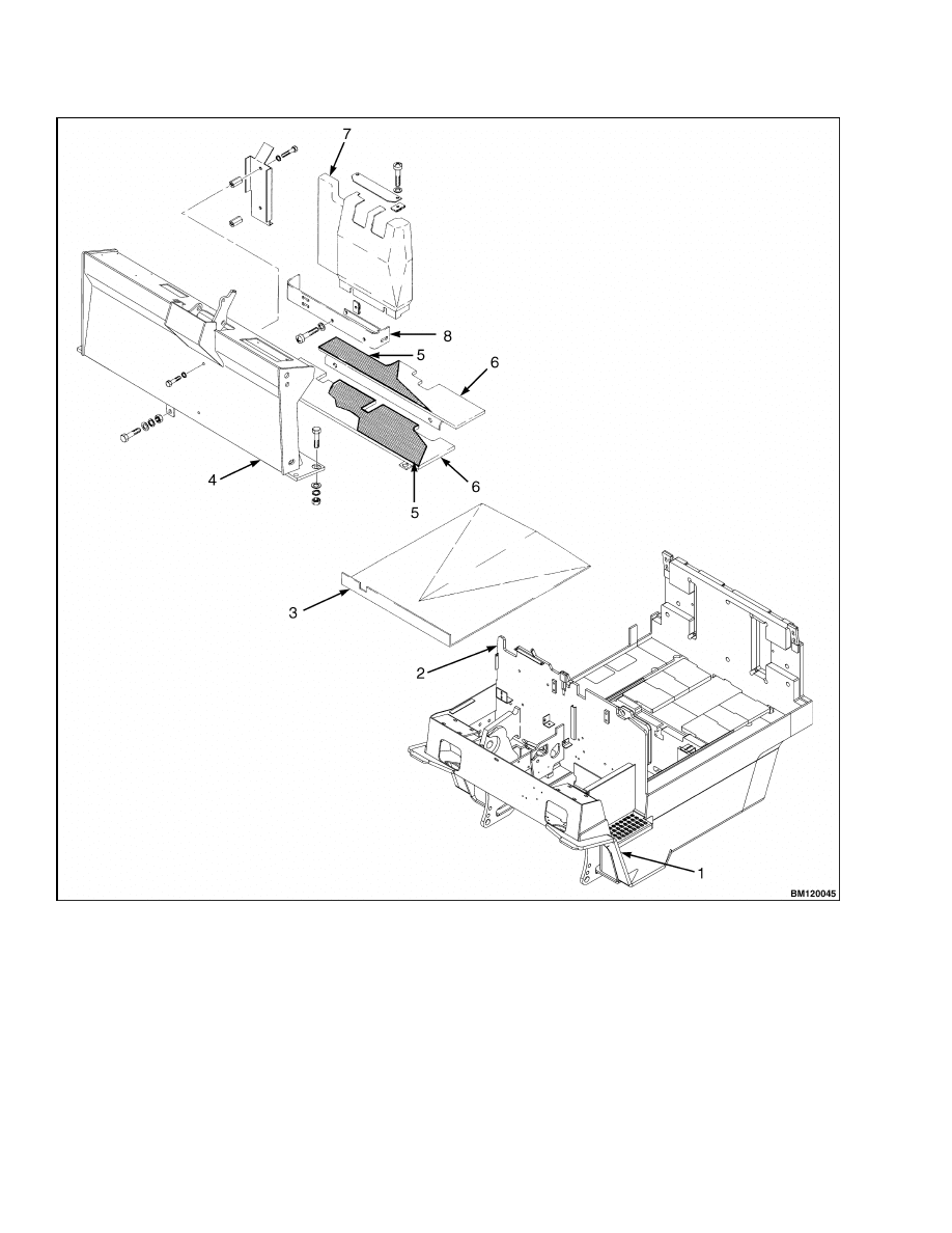
This section has a description and the service procedures for the parts of the frame. These parts include the
frame, counterweight assembly, overhead guard, hood and seat assembly, access panels, and label positions.
The procedure for removing the traction motor is also described in this section.
Description
The frame is a single weldment. See Figure 1. The
frame has mounts for the following:
• Counterweight
• Overhead guard
• Tilt cylinders
• Steering axle
• Drive axle assembly
The hydraulic tank is part of the lift truck frame and
is a welded steel unit. The lift trucks must have a
hood over the battery, or a covered battery if a hood
is not installed. The floor plates can be removed for
access to the hydraulic systems. A panel in the bot-
tom of the battery compartment can be removed for
access to the traction motor and the hydraulic pump
motor. The power steering pump and motor is located
under the floor plate on the left side of the lift truck.
The AC electronic controllers and contactors are in
the counterweight. A panel in the counterweight can
be removed for access to the AC controllers and con-
tactors.
The lift truck models E4.50XL and E4.50XLS (E100Z
and E100ZS) can have a short or long frame. See Bat-
tery Specifications section for the battery compart-
ment size and battery specifications.
WARNING
The battery must fit the battery compartment
so that the battery restraint will operate cor-
rectly. A loose battery can cause serious in-
jury and property damage if the lift truck over-
turns. Use spacers to prevent the battery from
moving more than 13 mm (0.5 in.) forward or
backward.
WARNING
Maximum clearance between the battery and
battery compartment width is 13 mm (0.5 in.).
Maximum clearance between the battery and
the spacer plate is also 13 mm (0.5 in.). The Bat-
tery Specifications chart shows the minimum
size compartment allowed.
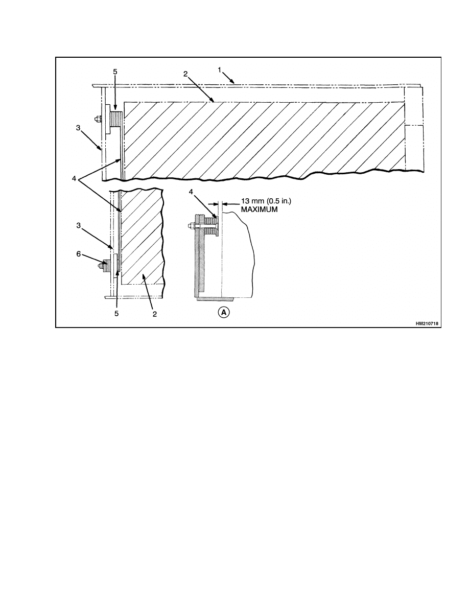
The lift trucks are equipped with adjustable spac-
ers in the battery compartment. See Figure 2. Add
or remove shims from under the front spacer bar to
control the movement of the battery in the forward
and backward directions. Install an equal number of
shims at each capscrew. Install the additional shims
under the nuts of the capscrews (outside battery com-
partment). The spacers on each side of the battery
can be adjusted to control the movement of the bat-
tery from side to side. Access to the nuts for the spac-
ers for the sides of the battery is under the frame near
the steer tires on all units. Tighten all capscrews. It
can be necessary to install the side spacers facing the
opposite direction for some batteries. If the spacers
cannot be adjusted for a battery that is specified for
this lift truck, see your Hyster lift truck dealer for
the correct spacers.
The weight of the battery is a large part of the coun-
terweight system on an electric lift truck. Make sure
that the battery is within the weight limits indicated
on the Nameplate. Each model of lift truck has a
cast-iron counterweight that provides the additional
weight necessary for the indicated capacity. A slot in
the overhead guard permits removal of the battery
without removing the overhead guard.
1
Description
100 SRM 1200
1.
SIDE STEP AND FENDER WELDMENT
2.
FRAME
3.
ACCESS PANEL
4.
COWL
5.
FLOOR MAT
6.
FLOOR PLATE
7.
COVER (HYDRAULIC LEVERS)
8.
PLATE
Figure 1. Lift Truck Frame, Floor Plates, and Covers
2
100 SRM 1200
Description
A. FRONT SPACER
1.
BATTERY COMPARTMENT
2.
BATTERY
3.
BULKHEAD
4.
SPACER BAR
5.
SHIM
6.
STORE ADDITIONAL SHIMS IN FRONT OF
BULKHEAD
Figure 2. Battery Spacer and Shims
3
Overhead Guard Repair
100 SRM 1200
Overhead Guard Repair
REMOVE
WARNING
Do not operate the lift truck without the over-
head guard correctly fastened to the lift truck.
WARNING
DO NOT weld mounts for lights or accessories
to legs of the overhead guard. Changes that are
made by welding, or by drilling holes that are
too big or in the wrong location, can reduce the
strength of the overhead guard.
See your dealer for Hyster lift trucks BEFORE
performing any changes to the overhead
guard.
No welding or drilling on legs of overhead guard is
permitted as per previous WARNING.
1.
Remove battery as described in the section Pe-
riodic Maintenance 8000 SRM 1201. See the
section Battery Specifications for information on
battery weights and sizes.
2.
Access to capscrews that hold rear supports of
overhead guard to counterweight is from the bat-
tery compartment. Remove capscrews.
3.
Remove two capscrews that hold each front sup-
port of overhead guard to cowl. Disconnect any
electric wires from under cowl that go through
supports of overhead guard.
When overhead
guard is lifted from the frame, make sure these
electric wires move through the holes in the cowl
so they are not damaged.
4.
Use lifting device or another person to help lift
overhead guard from lift truck.
INSTALL
1.
Put overhead guard on lift truck. Install any
electric wires from overhead guard supports
through holes in cowl.
2.
Install four capscrews, washers, and nuts that
hold front supports to cowl.
3.
Tighten capscrews to correct torque.
Install
capscrews and washers that hold rear supports
to counterweight. Tighten capscrews to correct
torque. The correct torque values are shown in
Figure 3 and Table 1. Install battery.
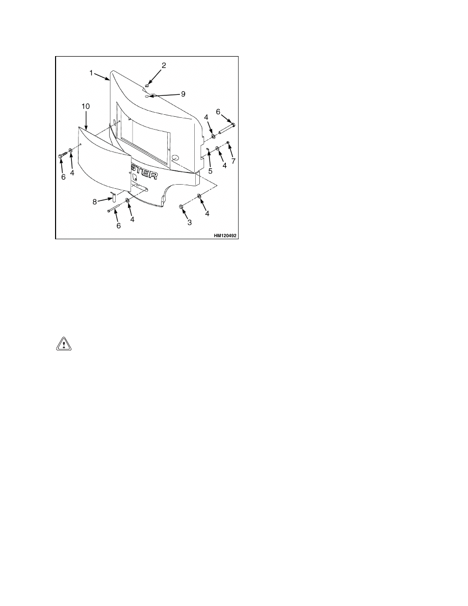
NOTE: OVERHEAD GUARD WITH CURVED LEGS
SHOWN. OVERHEAD GUARD MAY BE EQUIPPED
WITH STRAIGHT LEGS.
1.
OVERHEAD
GUARD (OHG)
2.
COUNTERWEIGHT
(CWT)
3.
FRAME
4.
CAPSCREWS (4)
OHG-FRONT
5.
CAPSCREWS (4)
OHG-REAR
6.
CAPSCREWS (2)
CWT-UPPER
7.
CAPSCREWS (2)
CWT-LOWER
Figure 3. Frame, Overhead Guard, and
Counterweight
Table 1. Torque Values
Overhead Guard
Counterweight
Model
Front
Rear
Upper
Lower
E3.50-5.50XL, E4.50XLS
(E70-120Z, E100ZS)
87 N•m
(64 lbf ft)
87 N•m
(64 lbf ft)
404 N•m
(298 lbf ft)
66 N•m
(49 lbf ft)
4
100 SRM 1200
Battery and Operator Restraint, Hood and Seat Brake Repair
Battery and Operator Restraint, Hood and Seat Brake Repair
BATTERY RESTRAINT AND HOOD REPAIR
WARNING
The battery restraint and its latch mechanisms
must operate correctly before a lift truck is op-
erated. Make sure the battery has a cover if the
lift truck does not have a hood.
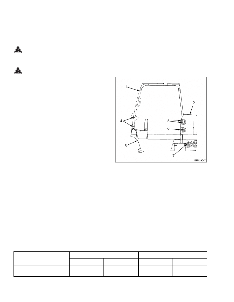
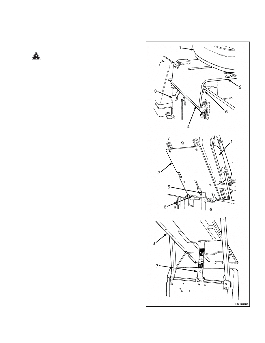
A battery restraint system is installed as a safety de-
vice. See Figure 4. The function of the battery re-
straint system, when correctly locked in the down po-
sition, is to hold the battery in the battery compart-
ment if an accident causes the lift truck to tip over.
The battery restraint is a steel plate that is connected
to the frame with a hinge. A sliding latch mechanism
locks the battery restraint in the down position for
operation. A knob near the hinge unlocks the battery
restraint from the frame so the battery restraint can
be raised to the up position for access to the battery.
The battery restraint is also the support for the seat.
A spring brace holds the seat and battery restraint in
the up position. A battery retention bar is fastened
to the counterweight with a hinge and is part of the
hood. Spacers are used inside the battery compart-
ment to prevent horizontal movement of the battery.
Legend for Figure 4
1.
SEAT
2.
BATTERY RESTRAINT PLATE
3.
KNOB FOR LATCH MECHANISM
4.
HINGE
5.
LATCH
6.
SPRING BRACE
7.
BATTERY RETENTION BAR
8.
HOOD
Figure 4. Battery Restraint and Seat Assembly
5
Battery and Operator Restraint, Hood and Seat Brake Repair
100 SRM 1200
NOTE: The steering column must be in the forward
position before raising the seat.
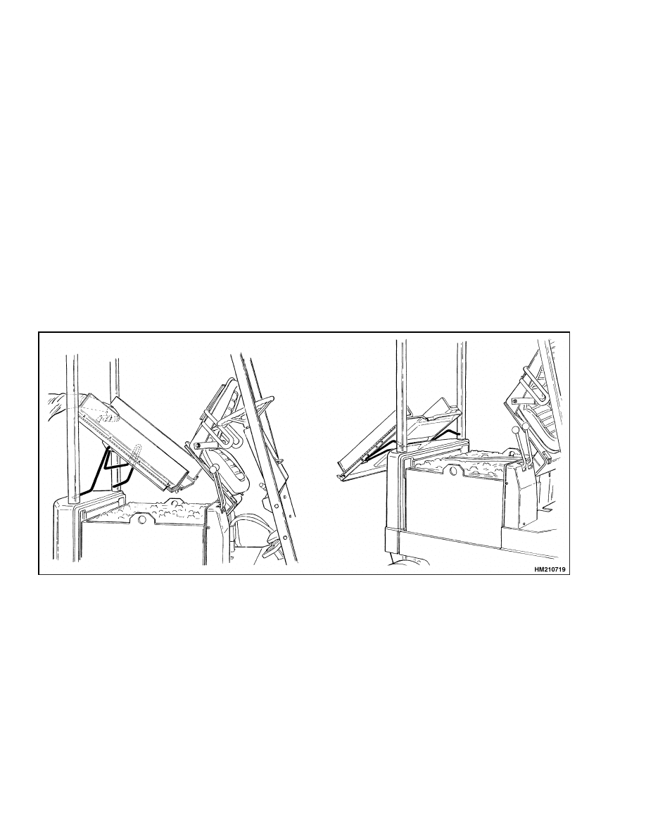
To raise the battery restraint and hood, the operator
must hold the handle on the restraint plate (handle
is located next to hip restraint on seat) with one hand
and with the other hand, pull down on the knob for
the latch mechanism to release the spring brace, and
then raise the seat assembly and battery restraint
plate toward the steering column. A spring brace will
hold the assembly in the up position. With the seat
assembly and battery restraint plate in the raised po-
sition, pull on the hood handles, located toward the
rear of the hood, to raise the hood toward the coun-
terweight. The hinged side plates must be flipped to
the center of the truck before raising the hood. See
Figure 5 and Figure 6.
Make sure that the battery cannot move more than
a total of 13 mm (0.5 in.)
in any one horizontal
direction.
Make sure the correct spacers are in-
stalled to prevent the movement. See your Hyster
lift truck dealer to replace damaged or missing
spacers. If a smaller battery of the correct weight
(see Nameplate) is installed and the spacers cannot
prevent movement, your Hyster lift truck dealer has
larger spacers.
To close the battery restraint and hood and to operate
correctly, the battery restraint plate must be locked
in the down position. Lower the battery retention
bar first, then pull the release knob to release the up
latch on the seat and lower the hood. Push the seat
and the battery restraint down until the latch locks to
lock the battery restraint plate in the down position
over the bar. Lift on battery restraint to make sure
it is latched securely to the frame and will not move.
Figure 5. Open Hood
6
100 SRM 1200
Battery and Operator Restraint, Hood and Seat Brake Repair
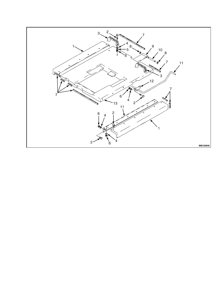
1.
HINGED SIDE PLATES
2.
CAPSCREW
3.
HOOD HANDLE (2)
4.
WASHER
5.
LOCKWASHER
6.
NUT
7.
ADHESIVE TRIM (SEAL)
8.
RETAINING RING
9.
PLATE (FOR BATTERY RESTRAINT BAR)
10. PIN
11. HINGE
12. BRACKET
13. HOOD
Figure 6. Hood Assembly
OPERATOR RESTRAINT REPAIR
There is an indicator light on the display panel for
the seat belt. The red light is ON as described in the
Operating Manual. The light can help the operator
remember to fasten the seat belt.
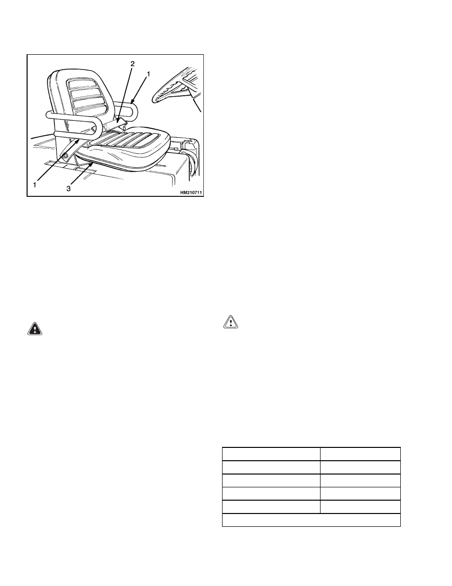
The seat belt, hip restraint brackets, seat and seat
rails, battery restraint (seat plate), and latch are all
part of the operator restraint system. See Figure 7.
Each item must be checked to make sure it is at-
tached securely, functions correctly, and is in good
condition.
The seat belt must latch securely. Make sure seat
belt extends and retracts smoothly and is not dam-
aged or torn. If seat belt cannot be pulled from re-
tractor assembly or is damaged, it must be replaced.
Make sure seat rails are not loose. Seat rails must
lock securely in position, but move freely when
unlocked. Seat rails must be securely attached to
mounting surface.
7
Counterweight Repair
100 SRM 1200
1.
HIP RESTRAINT
BRACKETS
2.
SEAT BELT
3.
SEAT RAILS
Figure 7. Operator Restraint System
SEAT BRAKE REPAIR
See the section Brake System 1800 SRM 338 for the
procedures for the seat brake.
Counterweight Repair
NOTE: If the lift truck must be put on blocks for
maintenance and repair, see the section How to Put
a Lift Truck on Blocks in the Operating Manual
or in the section Periodic Maintenance 8000 SRM
1201.
WARNING
The counterweight is very heavy. Make sure
that the crane and lifting devices have enough
lifting capacity to safely lift the counterweight.
The weights of the counterweights are shown
in Table 2.
The counterweight normally is not removed for most
repairs. Replacement of the AC controllers is ac-
complished by removing the cover from the counter-
weight. See Figure 8. The counterweight is fastened
to the frame with four capscrews. The weights for
the counterweights are shown in Table 2.
REMOVE
1.
Remove battery. See How to Change the Bat-
tery in the section Periodic Maintenance 8000
SRM 1201. See Battery Specifications section for
information on battery weights and sizes.
2.
Remove overhead guard as described in the para-
graphs under Overhead Guard Repair.
3.
Install lifting eyebolt in hole on top of counter-
weight. See Figure 8. Attach chain or sling to
eyebolt. Use crane to hold the weight of the coun-
terweight.
CAUTION
To prevent damage to the controller when re-
moving the counterweight, carefully lift coun-
terweight upward until it is off the frame, then
straight back from the lift truck.
4.
From inside the battery compartment, remove
two capscrews that hold counterweight to frame.
Remove two capscrews from tow pin area of coun-
terweight. Use crane to lift counterweight away
from frame. Make sure you do not damage the
electronic controls.
Table 2. Weight of Counterweights
Model
Weight*
E3.50XL (E70Z)
822 kg (1812 lb)
E4.00-4.50XL (E80-100Z)
1253 kg (2762 lb)
E4.50XLS (E100ZS)
1912 kg (4215 lb)
E5.50XL (E120Z)
1912 kg (4215 lb)
* ±50 kg (110 lb)
8
100 SRM 1200
Traction Motor Repair
1.
COUNTERWEIGHT
2.
PLUG
3.
NUT
4.
WASHER
5.
TAPE
6.
CAPSCREW
7.
LOCK NUT
8.
TOW PIN
9.
EYEBOLT HOLE
10. CONTROLLERS
COVER
Figure 8. Counterweight Assembly
INSTALL
CAUTION
To prevent damage to the controller when in-
stalling the counterweight, carefully move the
counterweight to the lift truck slightly above
the frame, then lower the counterweight to the
frame.
NOTE: The access panel to the controller can be
removed from the counterweight to make checks
and adjustments on the controller. Make sure lugs
are correctly engaged when access panel is installed
again or panel will fall from counterweight during
operation.
1.
Use crane to lift counterweight into position.
Make sure you do not damage controller.
In-
stall two upper capscrews from inside battery
compartment that hold counterweight to frame.
Install two lower capscrews in tow pin area of
counterweight.
Tighten capscrews to correct
torque. The correct torque values for capscrews
are shown in Figure 3.
2.
Disconnect sling or chain. Remove eyebolts from
counterweight.
3.
Install overhead guard as described in the para-
graphs for Overhead Guard Repair.
4.
Install battery. See How to Change the Bat-
tery in the section Periodic Maintenance 8000
SRM 1201. See Battery Specifications section for
information on battery weights and sizes.
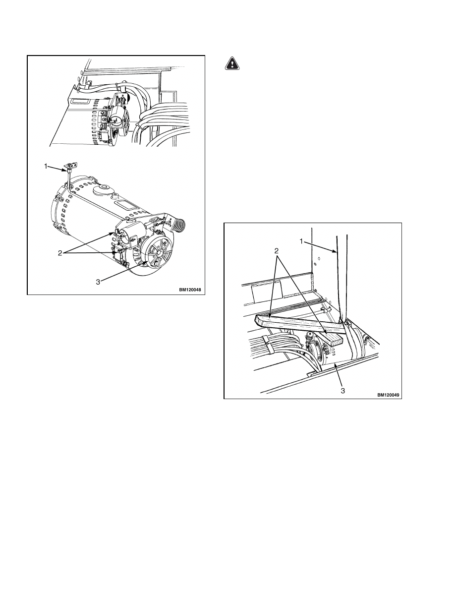
Traction Motor Repair
REMOVE
This procedure will show the removal of the trac-
tion motor through the battery compartment. The
lift trucks covered in this manual can have an op-
tional seat brake that actuates the brake on the ar-
mature shaft of the traction motor. See Figure 9. The
guide pipe connection and electrical connections for
the seat brake must be disconnected from the trac-
tion motor before the motor is removed. See the sec-
tion Brake System 1800 SRM 338 for seat brake ad-
justment procedures.
NOTE: The traction motor can also be removed from
under the lift truck with the use of a floor jack, but is
more difficult. The lift truck must be on blocks with
clearance for the jack and traction motor if the trac-
tion motor is removed from under the lift truck. See
the section How to Put a Lift Truck on Blocks in
the Operating Manual or in the section Periodic
Maintenance 8000 SRM 1201. The hydraulic lines
from the hydraulic tank must also be disconnected
if the traction motor is removed from under the lift
truck.
1.
Remove battery as described in the section Pe-
riodic Maintenance 8000 SRM 1201. Remove
floor plates and access panel in bottom of battery
compartment. See Figure 1.
9
Traction Motor Repair
100 SRM 1200
NOTE: TRACTION MOTOR WITH OPTIONAL SEAT
BRAKE SHOWN.
1.
GUIDE PIPE CONNECTION
2.
ELECTRICAL CONNECTION
3.
SEAT BRAKE
Figure 9. Traction Motor and Seat Brake
2.
If lift truck is equipped with a seat brake, discon-
nect seat brake guide pipe and electrical connec-
tions (see Figure 9). Disconnect hydraulic line to
main control valve so motor mount can be discon-
nected. Put caps on open hydraulic fittings.
3.
Disconnect power cables from traction motor.
Mark the cables and terminals for ease of recon-
necting.
4.
Put lift truck on blocks for easier access to bottom
bolts between traction motor and speed reducer.
Remove bolts between speed reducer and motor.
WARNING
Make sure the sling and crane can support the
weight of the traction motor. The traction mo-
tor on these lift trucks weighs approximately
204 kg (450 lb). Make sure the sling cannot slide
and permit traction motor to fall and cause in-
jury.
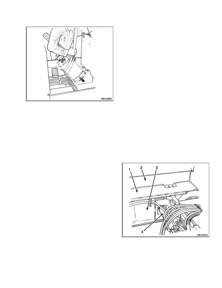
5.
Install sling to hold traction motor.
See Fig-
ure 10. Use wood block and board under sling as
shown in Figure 10. Use crane to hold weight of
traction motor. See Figure 11.
6.
Remove motor mount that holds traction motor
to frame. Pull traction motor from speed reducer.
7.
Use crane to move traction motor to a space to
make repairs.
NOTE: TRACTION MOTOR WITH OPTIONAL SEAT
BRAKE SHOWN.
1.
SLING
2.
USE WOOD BLOCK AND BOARD UNDER SLING
FOR A LEVER
3.
TRACTION MOTOR
Figure 10. Sling Installation to Lift Traction
Motor
10
100 SRM 1200
Hydraulic Tank Repair
NOTE: TRACTION MOTOR WITH OPTIONAL SEAT
BRAKE SHOWN.
Figure 11. Use Crane to Lift Traction Motor
INSTALL
1.
Install sling to lift traction motor. Use wood block
and board under sling as shown in Figure 10 to
control traction motor during installation.
2.
Lower traction motor into position in lift truck.
Align traction motor with speed reducer. See Fig-
ure 10.
3.
Use board or pry bar as necessary to push trac-
tion motor into speed reducer.
4.
Align bolt holes in speed reducer and motor
housing.
Install bolts that hold traction mo-
tor to speed reducer. Tighten bolts to 38 N•m
(28 lbf ft).
5.
Remove sling and install traction motor mount.
6.
Connect inlet hydraulic line to main control
valve. Install power cables.
7.
If seat brake was removed, connect seat brake
guide pipe and electrical connections. See Fig-
ure 9.
8.
Install floor plates and access panel in bottom of
battery compartment. See Figure 1. Install bat-
tery as described in the section Periodic Main-
tenance 8000 SRM 1201.
Hydraulic Tank Repair
INSPECT
Make a visual inspection of all sides of the tank. In-
spect welds for cracks and leakage. Check for wet ar-
eas, accumulation of dirt, and loose or missing paint
caused by leakage. Areas of the tank that are not eas-
ily seen can be checked with an inspection mirror and
a light that is approved for locations with flammable
vapors.
The hydraulic tank is part of the frame weldment and
cannot be removed from the lift truck. See Figure 12.
Repairs for leaks in the hydraulic tank can require
special procedures described in the next paragraphs.
1.
HYDRAULIC TANK
2.
OUTER FRAME
3.
INNER FRAME
4.
SUCTION PIPE
Figure 12. Hydraulic Tank
11

Hydraulic Tank Repair
100 SRM 1200
SMALL LEAKS, REPAIR
Use the following procedure to seal small leaks:
1.
Use steam to clean area around leak. Remove all
paint and dirt around leak.
WARNING
Do not use tools that can make sparks, heat, or
static electricity. The vapors in the tank can
cause an explosion.
2.
Apply Loctite
®
290 to leak. Follow instructions
of manufacturer.
LARGE LEAKS, REPAIR
1.
Use one of the procedures described under Clean
in this section to clean and prepare the tank for
repairs.
2.
Use acceptable welding practices to repair tank.
See the American National Standard Safety In
Welding and Cutting AWS Z 49.1 - 1999.
CLEAN
WARNING
Special procedures must be followed when
large leaks or other repairs need welding or
cutting. All work must be done by authorized
personnel. If the tank is cleaned inside of a
building, make sure there is enough ventila-
tion. See the following manuals for additional
information:
• Safe Practices for Welding and Cutting Con-
tainers That Have Held Combustibles by the
American Welding Society, F4.1 - 1999.
• Safety In Welding and Cutting, American Na-
tional Standard, AWS Z 49.1 - 1999.
When cleaning tank, do not use solutions that make
dangerous gases at normal temperatures or when
heated. Wear eye and face protection. Protect the
body from burns.
When cleaning with steam, use a hose with a mini-
mum diameter of 19 mm (0.75 in.). Control the pres-
sure of the steam by a valve installed at the nozzle of
the hose. If a metal nozzle is used, it must be made of
a material that does not make sparks. Make an elec-
trical connection between nozzle and tank. Connect
ground wire to tank to prevent static electricity.
Steam Method
Use the following procedure to clean the tank with
steam:
1.
Remove all parts from tank. Install drain plug.
2.
Fill tank 1/4 full with a solution of water and
sodium bicarbonate or sodium carbonate. Mix
0.5 kg (1 lb) per 4 liter (1 gal) of water.
WARNING
Compressed air can move particles so that they
cause injury to the user or to other personnel.
Make sure that the path of the compressed air
is away from all personnel.
Wear protective
goggles or a face shield to prevent injury to the
eyes.
3.
Mix solution in tank using air pressure. Make
sure all surfaces on inside of tank are flushed
with solution. Drain tank.
4.
Put steam into tank until tank does not have
odors and metal is hot. Steam vapors must come
from all openings.
5.
Flush inside of tank with boiling water. Make
sure all loose material is removed from inside of
tank.
6.
Make inspection of inside of tank. If it is not
clean, repeat Step 4 and Step 5 and make another
inspection. When making inspections, use a light
that is approved for locations with flammable va-
pors.
7.
Put plugs in all openings in tank. Wait 15 min-
utes, then remove inlet and outlet plugs. Test a
sample of the vapor with a special indicator for
gas vapors. If the amount of flammable vapors
is above the lower flammable limit, repeat the
cleaning procedures.
Chemical Solution Method
If the tank cannot be cleaned with steam, use the
following procedure:
1.
Mix a solution of water and trisodium phosphate
or a cleaning compound with an alkali base. Fol-
low the instructions given by the manufacturer.
12

100 SRM 1200
Safety Label Replacement
WARNING
Compressed air can move particles so that they
cause injury to the user or to other personnel.
Make sure that the path of the compressed air
is away from all personnel.
Wear protective
goggles or a face shield to prevent injury to the
eyes.
2.
Fill tank with cleaning solution. Use compressed
air to mix solution in tank.
3.
Drain tank. Flush inside of tank with hot (boil-
ing) water. Make sure all cleaning compound is
removed.
4.
Make an inspection of inside of tank. If tank is
not clean, repeat Step 1 through Step 3. Make
another inspection of tank. When making inspec-
tions, use a light that is approved for locations
with flammable vapors.
5.
Check tank for flammable vapors using a spe-
cial indicator for gas vapors. If the amount of
flammable vapors is above the lower flammable
limit, repeat the cleaning procedures.
ADDITIONAL PREPARATIONS FOR
REPAIR
If nitrogen gas or carbon dioxide gas is available, pre-
pare the tank for welding using these gases. See the
manual Safe Practices For Welding and Cutting Con-
tainers That Have Held Combustibles by the Ameri-
can Welding Society, F4.1 - 1999. If these gases are
not available, another method using water can be
used as follows:
1.
Fill tank with water to just below the point where
the work will be done. Make sure the space above
the level of the water has a vent.
2.
Use acceptable welding practices to repair tank.
See the American National Standard "Safety in
Welding and Cutting," AWS Z 49.1 - 1999.
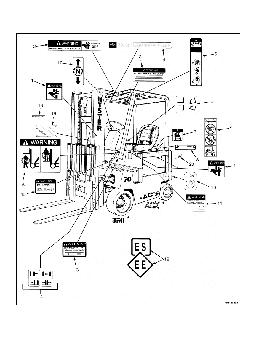
Safety Label Replacement
If the labels or information plates are missing or have
damage, they must be replaced. See Figure 13.
WARNING
WARNING or CAUTION labels must be re-
placed if they are damaged.
If a mast of
a different size or an accessory carriage is
installed, the capacity rating can change.
Changes in the kind of drive tires can change
the capacity rating. See a HYSTER Dealer for
a replacement Nameplate. The Nameplate in-
formation is a safety item and must be correct
for the equipment and configuration of the lift
truck.
NOTE: The Nameplate is installed using rivets. The
old rivets must be removed before installing a new
Nameplate.
1.
Make sure surface is dry and has no oil or grease.
Do not use solvent on new paint. Clean surface
of old paint using a cleaning solvent.
2.
Remove paper from back of label. Do not touch
adhesive surface.
3.
Carefully hold label in correct position above sur-
face. The label cannot be moved after it touches
the surface. Put label on surface. Make sure all
air is removed from under label and corners and
edges are tight.
13
Safety Label Replacement
100 SRM 1200
Figure 13. Label Positions
14

100 SRM 1200
Battery Specifications
Legend for Figure 13
NOTE: INSTALL NEW LABEL IN SAME LOCATION AS ORIGINAL.
NOTE: NOT ALL LABELS USED ON THESE LIFT TRUCK MODELS ARE SHOWN IN FIGURE 13. SEE THE
PARTS MANUAL FOR A COMPLETE LISTING OF ALL LABELS USED ON THESE LIFT TRUCKS.
1.
PINCH POINT LABEL
2.
MAST WARNING
3.
IMPACT RATING PLATE (OVERHEAD GUARD)
4.
OPERATOR WARNING
5.
LIFT/TILT LABEL
6.
OPERATOR RESTRAINT
7.
NO RIDERS
8.
UL CLASSIFICATION PLATE (US TRUCKS ONLY)
9.
BATTERY RESTRAINT
10. LIFTING EYE LABEL (EUROPEAN TRUCKS
ONLY)*
11. BATTERY SPACER WARNING
12. UL CLASSIFICATION LABEL (US TRUCKS
ONLY)
13. BATTERY DISCONNECT WARNING
14. AUXILIARY FUNCTION
15. PARKING BRAKE WARNING
16. MAST WARNING
17. FORWARD/REVERSE LABEL
18. NAMEPLATE LABEL
19. NAMEPLATE
20. RIVET
*LABEL USED ON EUROPEAN MODELS ONLY.
Battery Specifications
Table 3. Battery Specifications*
Battery Length
Weight
Model
Volts
Minimum
Compartment
Size Length ×
Width
Min./Max.
Min.
Max.
E3.50-4.00XL (E70-80Z)
36, 48,
80
841 × 987 mm
(33.1 × 38.9 in.)
950 to 990 mm
(37.4 to 39.0 in.)
1542 kg
(3400 lb)
2177 kg
(4799 lb)
E4.50XLS (E100ZS)
36, 48,
80
841 × 987 mm
(33.1 × 38.9 in.)
950 to 990 mm
(37.4 to 39.0 in.)
1633 kg
(3600 lb)
2177 kg
(4799 lb)
E4.50XL (E100Z)
36, 48,
80
694 × 1037 mm
(27.3 × 40.8 in.)
1115 to 1150 mm
(43.9 to 45.3 in.)
1814 kg
(4000 lb)
2517 kg
(5681 lb)
E5.50XL (E120Z)
36, 48,
80
993 × 1146 mm
(39.3 × 45.1 in.)
1115 to 1150 mm
(43.9 to 45.3 in.)
1919 kg
(4231 lb)
2517 kg
(5681 lb)
*BATTERY WIDTH
Batteries without cover: 950 to 1117 mm (37.4 to 44.0 in.)
Batteries with cover: 950 to 1143 mm (37.4 to 45.0 in.)
NOTE: Maximum tolerances are +0 and
13 mm (+0 and
0.5 in.) for the size of the battery compartment.
The battery specification chart shows the maximum size tolerances that will permit the battery to still fit into
a battery compartment.
15

NOTES
____________________________________________________________
____________________________________________________________
____________________________________________________________
____________________________________________________________
____________________________________________________________
____________________________________________________________
____________________________________________________________
____________________________________________________________
____________________________________________________________
____________________________________________________________
____________________________________________________________
____________________________________________________________
____________________________________________________________
____________________________________________________________
____________________________________________________________
____________________________________________________________
____________________________________________________________
____________________________________________________________
____________________________________________________________
____________________________________________________________
16


TECHNICAL PUBLICATIONS
100 SRM 1200
7/05 (3/05) Printed in United Kingdom
Document Outline
- toc
- tables
Wyszukiwarka
Podobne podstrony:
1596605 8000SRM1203 (07 2005) UK EN
1459370 1600SRM0720 (07 2005) UK EN
1554634 2200SRM1078 (07 2005) UK EN
1468474 2200SRM0756 (07 2005) UK EN
1586982 0100SRM1177 (03 2005) UK EN
1534732 0620SRM1053 (07 2005) UK EN
1580519 2200SRM1131 (07 2005) UK EN
1596604 8000SRM1202 (08 2005) UK EN(1)
1534733 1600SRM1054 (07 2005) UK EN
1556364 0620SRM1098 (07 2005) UK EN
1534735 2200SRM1056 (07 2005) UK EN
1459370 1600SRM0720 (07 2005) UK EN
więcej podobnych podstron