LIFT CYLINDERS
E3.50-5.50XL
3
(E70-120XL
3
) [C098];
H3.50-5.50XM (H70-120XM) [K005, L005];
S3.50-5.50XM (S70-120XM) [E004, F004];
E3.50-5.50XL, E4.50XLS
(E70-120Z, E100ZS) [D098]
PART NO. 1466169
4000 SRM 741

SAFETY PRECAUTIONS
MAINTENANCE AND REPAIR
• When lifting parts or assemblies, make sure all slings, chains, or cables are correctly
fastened, and that the load being lifted is balanced. Make sure the crane, cables, and
chains have the capacity to support the weight of the load.
• Do not lift heavy parts by hand, use a lifting mechanism.
• Wear safety glasses.
• DISCONNECT THE BATTERY CONNECTOR before doing any maintenance or repair
on electric lift trucks. Disconnect the battery ground cable on internal combustion lift
trucks.
• Always use correct blocks to prevent the unit from rolling or falling. See HOW TO PUT
THE LIFT TRUCK ON BLOCKS in the Operating Manual or the Periodic Mainte-
nance section.
• Keep the unit clean and the working area clean and orderly.
• Use the correct tools for the job.
• Keep the tools clean and in good condition.
• Always use HYSTER APPROVED parts when making repairs. Replacement parts
must meet or exceed the specifications of the original equipment manufacturer.
• Make sure all nuts, bolts, snap rings, and other fastening devices are removed before
using force to remove parts.
• Always fasten a DO NOT OPERATE tag to the controls of the unit when making repairs,
or if the unit needs repairs.
• Be sure to follow the WARNING and CAUTION notes in the instructions.
• Gasoline, Liquid Petroleum Gas (LPG), Compressed Natural Gas (CNG), and Diesel fuel
are flammable. Be sure to follow the necessary safety precautions when handling these
fuels and when working on these fuel systems.
• Batteries generate flammable gas when they are being charged. Keep fire and sparks
away from the area. Make sure the area is well ventilated.
NOTE: The following symbols and words indicate safety information in this
manual:
WARNING
Indicates a condition that can cause immediate death or injury!
CAUTION
Indicates a condition that can cause property damage!
Lift Cylinders
Table of Contents
TABLE OF CONTENTS
Safety Procedures When Working Near Mast..................................................................................................
General ...............................................................................................................................................................
Description .........................................................................................................................................................
Lowering Control Valve (Velocity Fuse) .......................................................................................................
Lift Cylinder Repair...........................................................................................................................................
Remove ...........................................................................................................................................................
Disassemble ...................................................................................................................................................
Assemble ........................................................................................................................................................
Install .............................................................................................................................................................
Lift System Leak Check ....................................................................................................................................
Troubleshooting..................................................................................................................................................
This section is for the following models:
E3.50-5.50XL
3
(E70-120XL
3
) [C098];
H3.50-5.50XM (H70-120XM) [K005, L005];
S3.50-5.50XM (S70-120XM) [E004, F004];
E3.50-5.50XL, E4.50XLS (E70-120Z, E100ZS) [D098]
©2005 HYSTER COMPANY
i

"THE
QUALITY
KEEPERS"
HYSTER
APPROVED
PARTS

4000 SRM 741
Safety Procedures When Working Near Mast
Safety Procedures When Working Near Mast
The following procedures MUST be used when in-
specting or working near the mast. Additional pre-
cautions and procedures can be required when re-
pairing or removing the mast.
WARNING
Mast parts are heavy and may shift. Distances
between parts are small. Serious injury can re-
sult if part of the body is hit by parts of the mast
or the carriage.
• Never put any part of the body into or under
the mast or carriage unless all parts are com-
pletely lowered or a safety chain is installed.
Make sure the power is OFF and the battery
is disconnected. Put a DO NOT OPERATE tag
in the operator’s compartment.
• Be careful of the forks.
When the mast is
raised, the forks can be at a height to cause
an injury.
• DO NOT climb on the mast or lift truck at any
time. Use a ladder or personnel lift to work
on the mast.
• DO NOT use blocks to support the mast weld-
ments nor to restrain their movement.
• Mast repairs require disassembly and re-
moval of parts and can require removal of
the mast or carriage. Follow the repair pro-
cedures in the correct Service Manual for
the mast.
WHEN WORKING NEAR THE MAST ALWAYS:
• Lower the mast and carriage completely.
Push the lift/lower control lever forward and
make sure there is no movement in the mast.
Make sure all parts of the mast that move are
fully lowered.
OR
• If parts of the mast must be in a raised po-
sition, install a safety chain to restrain the
moving parts of the mast. Connect moving
parts to a part that does not move. Follow
these procedures:
1.
Put mast in a vertical position.
2.
Raise mast to align bottom crossmember of weld-
ment that moves in outer weldment with a cross-
member on outer weldment. On two-stage and
free-lift mast, the moving part is the inner weld-
ment. On three-stage mast, it is the intermediate
weldment. See Figure 1.
3.
Use a 3/8-inch minimum safety chain with a hook
to fasten cross members together so the movable
member cannot lower. Put hook on back side
of mast. Make sure hook is completely engaged
with a link in the chain. Make sure safety chain
does not touch lift chains or chain sheaves, tubes,
hoses, fittings, or other parts on the mast.
4.
Lower mast until there is tension in safety chain,
and free-lift cylinder (two-stage full free-lift and
three-stage masts only) is completely retracted.
If running, stop engine. Apply parking brake. In-
stall a DO NOT REMOVE tag on safety chain(s).
5.
Install another safety chain (3/8 inch minimum)
between top or bottom crossmember of carriage
and a crossmember on outer weldment.
NOTE: After lowering or restraining the mast, shut
off the power and remove the key. Put a DO NOT
OPERATE tag in the operator’s compartment.
1

Safety Procedures When Working Near Mast
4000 SRM 741
A. TWO-STAGE LFL MAST
B. TWO-STAGE FFL MAST
C. THREE-STAGE FFL MAST
1.
OUTER WELDMENT
2.
INNER WELDMENT
3.
INTERMEDIATE WELDMENT
4.
HOOK
5.
FREE-LIFT CYLINDER
6.
CROSSMEMBER
7.
CROSSMEMBER
Figure 1. Safety Chain the Mast
2

4000 SRM 741
Description
General
This section has the description for lift cylinders used on the masts for model lift trucks S3.50-5.50XM (S70-
120XM), H3.50-5.50XM (H70-120XM), E3.50-5.50XL
3
(E70-120XL
3
) and E3.50-5.50XL, E4.50XLS (E70-120Z,
E100ZS) [D098] and the instructions for their repair. The operation and repair procedures for the different lift
cylinders are similar. See the section Lift Cylinders 4000 SRM 135 for lift cylinders used on other units.
Description
All lift cylinders for the masts are single-action hy-
draulic cylinders. The hydraulic force is applied only
in one direction. When hydraulic oil enters one end
of the lift cylinder, the hydraulic force extends the
piston rod. When the force is removed, the weight of
the carriage and inner mast causes the piston rod to
retract.
A common maintenance problem is the repair of oil
leaks. If the bore of the shell of the lift cylinder is
damaged and cannot be repaired, the lift cylinder
must be replaced.
The two-stage and three-stage masts have two main
lift cylinders. The free-lift mast has two main lift
cylinders and a shorter free-lift cylinder. See Fig-
ure 2 and Figure 3.
Spacers are used in some cylinders to limit the stroke
of the piston rod. Worn spacers must be replaced
with the same size spacer.
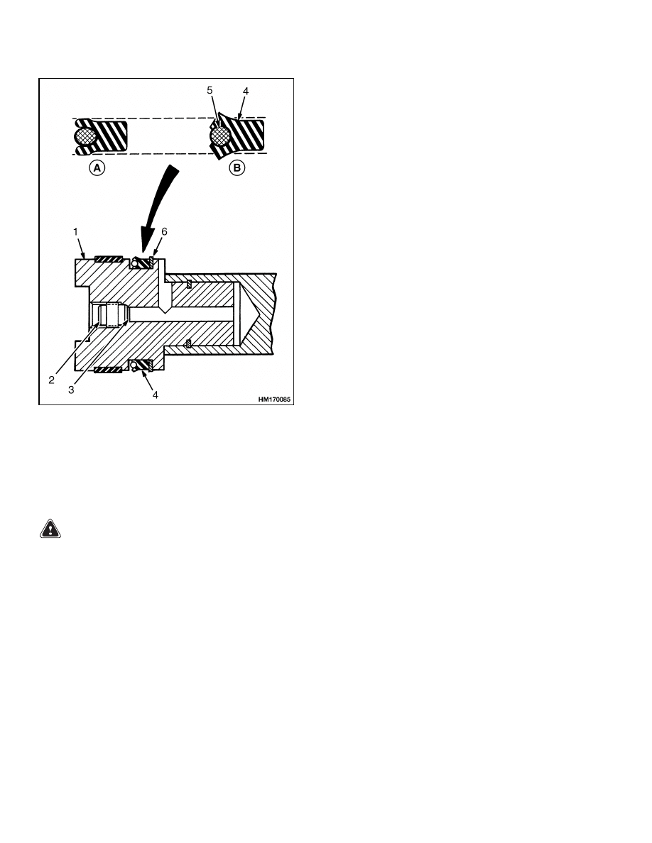
The free-lift cylinder has a single-lip seal on the pis-
ton to prevent hydraulic oil leaks past the piston and
retainer. The piston rod has a smaller diameter than
the piston.
During operation, some hydraulic oil will leak past
the piston area to the rod end of the lift cylinder.
Small leaks are permitted if the internal leak rate
of the hydraulic system is not greater than the spec-
ification. An internal check valve is installed in the
piston of the free-lift cylinders. When the piston rod
extends, the pressure increases more quickly on any
oil in the rod end of the lift cylinder. The hydraulic oil
transfers through the check valve to the piston end of
the free-lift cylinder. This action prevents hydraulic
damage to the single-lip seal and the wiper ring. See
Figure 4.
LOWERING CONTROL VALVE (VELOCITY
FUSE)
A lowering control valve is installed in the hydraulic
line to the bases of the main lift cylinders and at the
inlet port of each lift cylinder. The lowering control
valves (velocity fuses) permit easy entry of hydraulic
oil into the cylinders, but give a restriction when the
rods retract. This restriction controls the maximum
speed at which a load on the forks can be lowered.
The lowering control valves (velocity fuses) prevent
a load on the forks from freely falling if a hydraulic
hose breaks.
3
Description
4000 SRM 741
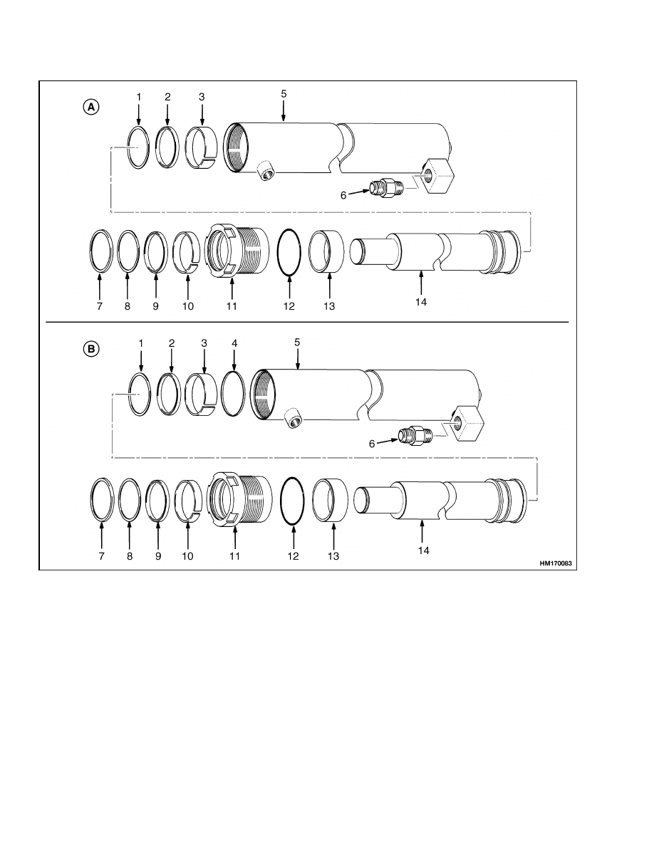
A. TWO-STAGE MAST
B. THREE-STAGE MAST
1.
PISTON U-CUP SEAL
2.
BACKUP RING
3.
WEAR RING
4.
PISTON RING
5.
SHELL
6.
LOWERING CONTROL VALVE (VELOCITY
FUSE)
7.
WIPER RING, ROD
8.
BACKUP RING
9.
ROD SEAL
10. WEAR RING
11. RETAINER
12. O-RING
13. SPACER
14. ROD ASSEMBLY
Figure 2. Main Lift Cylinders
4
4000 SRM 741
Description
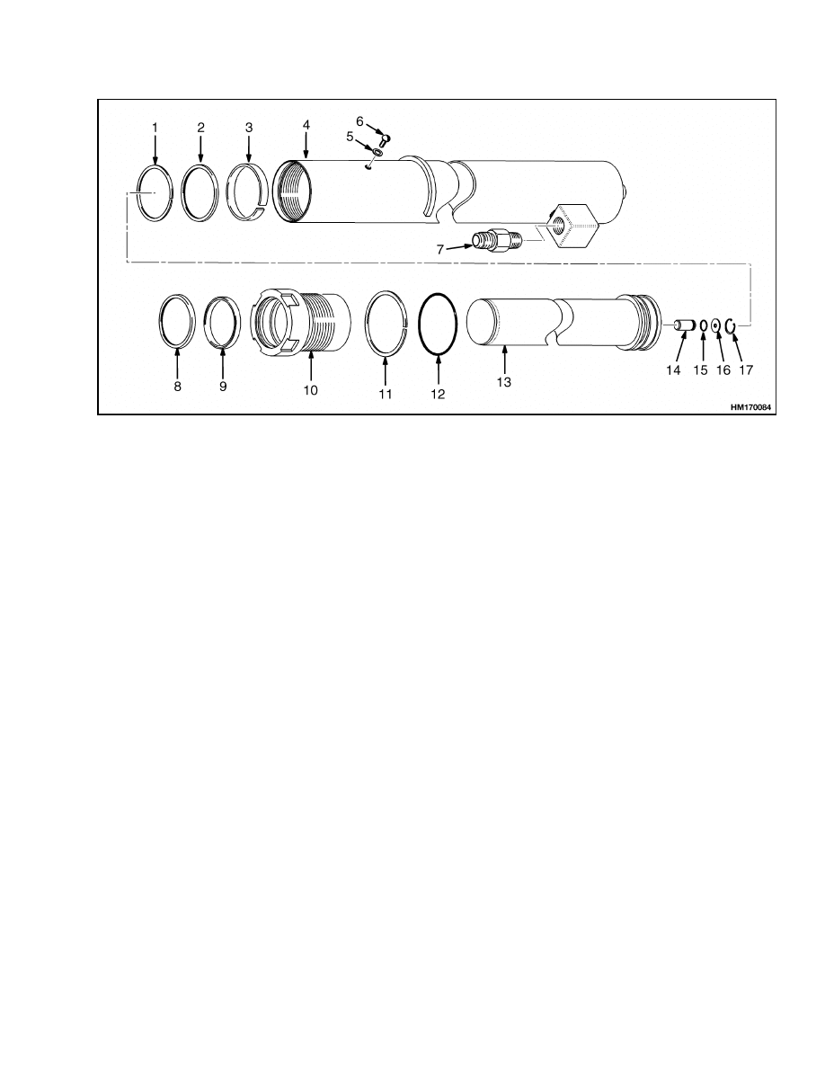
1.
BACKUP RING
2.
SEAL
3.
WEAR RING
4.
SHELL
5.
WASHER, SEAL
6.
SCREW, BUTTON HEAD
7.
LOWERING CONTROL VALVE (VELOCITY
FUSE)
8.
WIPER, ROD
9.
SEAL, ROD
10. RETAINER
11. BACKUP RING
12. O-RING
13. ROD ASSEMBLY
14. CHECK VALVE
15. O-RING
16. WASHER
17. SNAP RING
Figure 3. Free-Lift Cylinder
5
Lift Cylinder Repair
4000 SRM 741
Figure 4. Internal Check Valve and Single Lip
Seal
Legend for Figure 4
A. INSTALLED
B. NOT INSTALLED
1.
PISTON AND ROD
ASSEMBLY
2.
CHECK VALVE
3.
O-RING
4.
SINGLE-LIP SEAL
5.
O-RING
6.
BACKUP RING
Lift Cylinder Repair
REMOVE
WARNING
Connect slings and a crane to the top of the
inner mast (and intermediate mast, if it is a
three-stage mast) using chains. If it is a three-
stage mast, make sure all masts are fastened to-
gether. Make sure the chains will not damage
the sheaves, tubing, or other parts of the mast.
Make sure the crane and slings can lift the load
correctly.
NOTE: Remove the carriage before removing the lift
cylinders. See the procedure described in the Mast
section. If the mast assembly must be removed for
repairs, then remove the lift cylinders when the
mast assembly is disassembled. When only the lift
cylinder must be removed for repairs, remove the lift
cylinders from the mast as described in the following
paragraphs.
1.
Clean area around lift cylinder hydraulic fittings.
Disconnect fittings at the lift cylinders and put
caps on open lines.
2.
On free-lift mast, remove pins for the lift chains
at chain anchors, and remove capscrews, wash-
ers, and clamp that hold free-lift cylinder to in-
ner weldment. Remove free-lift cylinder.
3.
Remove snap rings and washers from top of
each main lift cylinder. Remove cylinder clamps
near top of each lift cylinder. Two capscrews and
washers are used to fasten each cylinder clamp
to outer mast top crossmember.
4.
Remove capscrews, washers, and brackets from
mounts at bottom of each lift cylinder.
5.
Support cylinder. Connect a crane to top of in-
ner mast using chains. Raise inner mast from
outer mast approximately 30 cm (12 in.). Dis-
engage piston rod ends of lift cylinders from top
6

4000 SRM 741
Lift Cylinder Repair
crossmember of inner mast. Remove lift cylin-
ders from mount plates at bottom of outer mast.
DISASSEMBLE
WARNING
Use slings and a crane to handle and disassem-
ble the lift cylinders of most lift trucks. Make
sure the crane and slings can lift the load cor-
rectly.
CAUTION
Carefully disassemble and assemble the lift
cylinders so the piston rods and sliding sur-
faces are not damaged.
NOTE: Disassembly of the main lift cylinders and the
free-lift cylinder is similar. All lift cylinders are dis-
assembled from the rod end of the cylinder shell.
1.
Loosen retainer with a spanner. See Figure 2 and
Figure 3.
2.
Remove retainer from shell. Remove and discard
wiper ring, backup ring, rod seal, wear ring, and
O-ring.
3.
Remove protective cap from inlet and slide rod
and piston assembly from shell. Drain hydraulic
oil into a container.
4.
Remove wear ring, single-lip seal, and backup
ring from rod assembly.
5.
Remove internal check valve, if installed, from
base of the lift cylinder.
6.
Remove lowering control valve (velocity fuse).
7.
Clean all parts. Check sliding surfaces for dam-
age. Repair or replace any damaged parts.
ASSEMBLE
Refer to Figure 2 and Figure 3 for the following steps.
CAUTION
A difficult and important step in assembling
lift cylinders is the correct installation of the
seals. Most lift cylinder maintenance is caused
by seal leaks. Special tools are available from
Hyster Parts and Service.
See Parts-Service
Gram L-A-2 (Latest Revision) for the available
tools.
NOTE:
• Lubricate all internal parts of the lift cylinder with
hydraulic oil during assembly.
• Use new O-rings and seals. Apply lubricant (hy-
draulic oil) during assembly.
Packing lubricant
(Part No. 186061) is also available.
• Make sure the single-lip seal assemblies are in-
stalled with the O-ring toward the base of the lift
cylinder. See Figure 4.
1.
Install internal check valve if removed. Make
sure arrow on internal check valve is toward base
of piston.
2.
Install wear ring, single-lip seal, and backup ring
onto rod assembly. If a spacer sleeve is used,
install it. Use shim material and a clamp as a
guide to move single-lip seal over threads of shell.
NOTE: Do not use an adhesive on the threads of the
piston rod and piston.
3.
Carefully push rod assembly into shell. Release
clamp on seal when seal has travelled past
threads of shell.
4.
Install seal, backup ring, O-ring, wear ring, and
wiper ring in retainer.
The wiper side of the
wiper seal must be toward base of the lift cylin-
der. See Figure 4.
5.
Carefully install retainer on piston rod.
6.
The retainer for the free lift cylinder used on
S3.50-5.50XM (S70-120XM) and E3.50-5.50XL
3
(E70-120XL
3
)
[C098],
and
E3.50-5.50XL,
E4.50XLS (E70-120Z, E100ZS) [D098] lift truck
is tightened to 340 to 410 N•m (250 to 300 lbf ft).
7.
Engage threads and tighten retainer to 340 to
410 N•m (250 to 300 lbf ft) for the main lift cylin-
der and 542 to 644 N•m (400 to 475 lbf ft) on the
free-lift cylinder. Use a correct spanner. Do not
hit the retainer with a hammer and driver.
8.
Install lowering control valve (velocity fuse).
7
Lift System Leak Check
4000 SRM 741
INSTALL
WARNING
Connect slings and a crane to the top of the
inner mast (and intermediate mast, if it is a
three-stage mast) using chains. If it is a three-
stage mast, make sure all masts are fastened to-
gether. Make sure the chains will not damage
the sheaves, tubing, or other parts of the mast.
Make sure the crane and slings can lift the load
correctly.
NOTE: The clamp blocks used to hold the free-lift
cylinder are designed to conform to different cylin-
der diameters depending on which side contacts the
cylinder. Be sure the blocks conform properly to the
cylinder shell.
1.
Install main lift cylinders to mounts at base of
outer mast. Use a crane and lower inner mast
to engage piston rods of lift cylinders to holes in
top crossmember of inner mast. Install washers
and snap rings, or other locking device, at top of
lift cylinders. Install cylinder clamps to brack-
ets mounted to outer weldment near top of each
cylinder and tighten nuts to 18 N•m (13 lbf ft).
2.
Install brackets, capscrews, and washers on bot-
tom mounts of each main lift cylinder.
3.
When inner mast is lowered, install free-lift
cylinder in inner mast. A pin in the base of the
lift cylinder will fit into the cylinder mount at
the base of the inner mast. Fasten upper end
of cylinder to center crossmember with clamp
blocks, washers, and capscrews. Tighten cap-
screws to 121 N•m (89 lbf ft).
Install chain
sheave and brackets to the top of free-lift piston
rod.
4.
Connect hydraulic lines and fittings at the lift
cylinders.
5.
Install chain sheaves and brackets. Connect lift
chains to chain anchors on inner mast. Fasten
wires between ends of the lift chains so they can
be controlled during installation of carriage.
6.
Install carriage. Connect the lift chains.
Lift System Leak Check
WARNING
Never allow anyone under a raised carriage.
Do not put any part of your body through the
lift mechanism unless all parts of the mast are
completely lowered and the engine is stopped.
Before making any repairs, use blocks and
chains on the mast and carriage so they can-
not move.
Make sure the moving parts are
attached to the parts that cannot move.
Do not try to find hydraulic leaks by putting hy-
draulic components under pressure or putting
hands on pressurized components. Hydraulic
oil can be injected into the body by pressure.
During the test procedures for the hydraulic
system, fasten the load to the carriage with
chains to prevent it from falling.
Keep all
personnel away from the lift truck during the
tests.
NOTE: See the procedures in the mast repair sec-
tions for lift chain adjustments, mast adjustments,
carriage adjustment, and header hose roller adjust-
ment.
1.
Operate hydraulic system. Put a capacity load
on forks and raise and lower load several times.
Lower load and tilt mast forward and backward
several times. Check for leaks.
2.
Raise carriage and load 1 m (3 ft). If carriage
lowers slowly with control valve in a NEUTRAL
position, there are leaks inside the hydraulic sys-
tem. Maximum speed the carriage is allowed to
lower is 50 mm (2 in.) per 10 minutes when hy-
draulic oil is 30 C (90 F). If oil temperature is
70 C (160 F), maximum speed the carriage can
lower is 150 mm (6 in.) per 10 minutes.
3.
Check lift cylinder for internal leaks. Remove
load from forks. Install a gate valve in supply
line between main control valve and mast. Put a
capacity load on forks again. Raise carriage 1 m
(3 ft). Close gate valve. If carriage or mast lowers
slowly, seals in the lift cylinders have leaks.
4.
If carriage does not move, open gate valve and
check for movement again. If carriage lowers
when gate valve is open, check for leaks in hy-
draulic lines and fittings. If no leaks are found,
the main control valve can have a defect. Remove
load from forks.
8

4000 SRM 741
Troubleshooting
Troubleshooting
PROBLEM
POSSIBLE CAUSE
PROCEDURE OR ACTION
No movement of the lift
cylinders.
Pilot line(s) to the control valve are
disconnected or leaking.
Tighten or connect fittings.
No oil or not enough oil in the hy-
draulic tank.
Fill tank. Check for leaks.
Relief valve(s) not set correctly.
Adjust or install new relief valve.
Hydraulic pump does not operate or
has damage.
Repair or install new pump.
Remote control valve does not oper-
ate.
Check and repair valve.
Slow movement of the lift
cylinders.
No oil or not enough oil to the lift
cylinders.
Fill tank. Check for leaks.
Cylinders have internal or external
leaks.
Repair leaks. Install new parts.
Relief valve is not set correctly.
Adjust or install new relief valve.
There is a restriction in a hydraulic
line.
Remove restriction.
Install new
parts.
Load is more than capacity.
Reduce load.
Rough movement of the mast
assembly.
There is air in the hydraulic system.
Remove air. Check for loose connec-
tions or breaks in lines.
Lift cylinder(s) is damaged.
Repair or install new lift cylinder.
Mast weldments are damaged or not
aligned.
Align weldments. Install new parts.
Mast weldments are not lubricated
correctly.
Lubricate correctly.
Load rollers or bearing blocks are
damaged or not adjusted correctly.
Replace or adjust load rollers or bear-
ing blocks.
Lift chains are damaged.
Replace lift chains.
9

Troubleshooting
4000 SRM 741
PROBLEM
POSSIBLE CAUSE
PROCEDURE OR ACTION
Lift or tilt cylinders extend
or retract when the control
valve lever (spool) is in the
NEUTRAL position.
Load check valves and spools have
damage.
Repair or install new load check
valve and spool.
Cylinder seals have leaks.
Install new seals.
Hydraulic lines have leaks.
Repair leaks. Install new parts. Re-
move air from system.
Leaks between spool and bore.
Install new spool and O-ring seals.
10


TECHNICAL PUBLICATIONS
4000 SRM 741
3/05 (10/03)(11/01)(8/99) Printed in United Kingdom
Document Outline
Wyszukiwarka
Podobne podstrony:
więcej podobnych podstron