PERIODIC
MAINTENANCE
REACHSTACKER
RS45-30CH, RS45-27IH, RS46-33CH, RS46-30IH,
RS46-36CH, RS46-33IH Up to 1528, 1530,
1531, and 1532 [A222]
PART NO. 1458783
8000 SRM 592

SAFETY PRECAUTIONS
MAINTENANCE AND REPAIR
• When lifting parts or assemblies, make sure all slings, chains, or cables are correctly
fastened, and that the load being lifted is balanced. Make sure the crane, cables, and
chains have the capacity to support the weight of the load.
• Do not lift heavy parts by hand, use a lifting mechanism.
• Wear safety glasses.
• DISCONNECT THE BATTERY CONNECTOR before doing any maintenance or repair
on electric lift trucks. Disconnect the battery ground cable on internal combustion lift
trucks.
• Always use correct blocks to prevent the unit from rolling or falling. See HOW TO PUT
THE LIFT TRUCK ON BLOCKS in the Operating Manual or the Periodic Mainte-
nance section.
• Keep the unit clean and the working area clean and orderly.
• Use the correct tools for the job.
• Keep the tools clean and in good condition.
• Always use HYSTER APPROVED parts when making repairs. Replacement parts
must meet or exceed the specifications of the original equipment manufacturer.
• Make sure all nuts, bolts, snap rings, and other fastening devices are removed before
using force to remove parts.
• Always fasten a DO NOT OPERATE tag to the controls of the unit when making repairs,
or if the unit needs repairs.
• Be sure to follow the WARNING and CAUTION notes in the instructions.
• Gasoline, Liquid Petroleum Gas (LPG), Compressed Natural Gas (CNG), and Diesel fuel
are flammable. Be sure to follow the necessary safety precautions when handling these
fuels and when working on these fuel systems.
• Batteries generate flammable gas when they are being charged. Keep fire and sparks
away from the area. Make sure the area is well ventilated.
NOTE: The following symbols and words indicate safety information in this
manual:
WARNING
Indicates a condition that can cause immediate death or injury!
CAUTION
Indicates a condition that can cause property damage!

Periodic Maintenance
Table of Contents
TABLE OF CONTENTS
General ...............................................................................................................................................................
Serial Number Data ......................................................................................................................................
Engine Shutoff System..................................................................................................................................
How to Move Disabled ReachStacker ...........................................................................................................
How to Tow ReachStacker ........................................................................................................................
How to Put ReachStacker on Blocks ............................................................................................................
How to Raise Drive Tires ..........................................................................................................................
How to Raise Steering Tires .....................................................................................................................
Maintenance Schedule.......................................................................................................................................
Maintenance Procedures Every 8 Hours or Daily............................................................................................
How to Make Checks With Engine Stopped.................................................................................................
Tires and Wheels .......................................................................................................................................
Safety Labels .............................................................................................................................................
Fuel, Oil, or Coolant Leaks Check............................................................................................................
Drive Belts .................................................................................................................................................
Battery .......................................................................................................................................................
Engine Oil ..................................................................................................................................................
Drain Water from Fuel Filter ...................................................................................................................
Hydraulic System ......................................................................................................................................
Cooling System ..........................................................................................................................................
Air Filter ....................................................................................................................................................
Boom and Spreader ...................................................................................................................................
How to Make Checks With Engine Running................................................................................................
Gauges, Indicator Lights, Horn, Fuses, and Relays................................................................................
Control Levers and Pedals........................................................................................................................
Electrical System.......................................................................................................................................
Transmission Oil .......................................................................................................................................
Steering System ........................................................................................................................................
Service Brakes ...........................................................................................................................................
Parking Brake ...........................................................................................................................................
Engine Oil ..................................................................................................................................................
Cooling System ..........................................................................................................................................
Hydraulic System ......................................................................................................................................
Boom and Spreader Operation .................................................................................................................
Maintenance Procedures Every 250 Hours or Monthly...................................................................................
Engine and Oil Filter.....................................................................................................................................
Brake System Oil...........................................................................................................................................
Battery ...........................................................................................................................................................
Wheel Nuts.....................................................................................................................................................
Steering Axle Tie Rods ..................................................................................................................................
Drive Shaft Joints..........................................................................................................................................
Drive Axle and Differential Oil.....................................................................................................................
General Lubrication ......................................................................................................................................
Maintenance Procedures Every 500 Hours or 3 Months .................................................................................
Hydraulic Filter .............................................................................................................................................
Fuel Filter/Water Separator..........................................................................................................................
Transmission Filter .......................................................................................................................................
Coolant Filter.................................................................................................................................................
Maintenance Procedures Every 1000 Hours or 6 Months ...............................................................................
Transmission Oil............................................................................................................................................
Brake System Filter ......................................................................................................................................
©2005 HYSTER COMPANY
i
Table of Contents
Periodic Maintenance
TABLE OF CONTENTS (Continued)
Disc Brakes ....................................................................................................................................................
Cleaning Procedures .................................................................................................................................
Inspect........................................................................................................................................................
Maintenance Procedures Every 2000 Hours or Annually ...............................................................................
Engine Coolant ..............................................................................................................................................
Hydraulic Oil .................................................................................................................................................
Change Hydraulic Oil ...............................................................................................................................
Hydraulic Tank Breather..........................................................................................................................
Drive Axle and Differential Oil.....................................................................................................................
Wheels and Tires................................................................................................................................................
Remove Wheels ..............................................................................................................................................
Remove Wheel From Tire..............................................................................................................................
Install Tire on Wheel .....................................................................................................................................
Install Wheel in Tire......................................................................................................................................
Add Air to Tires .............................................................................................................................................
Install Wheels ................................................................................................................................................
How to Store ReachStacker...........................................................................................................................
Short-Term Storage ...................................................................................................................................
Long-Term Storage ....................................................................................................................................
How to Move a ReachStacker on a Transport ..............................................................................................
Loading ......................................................................................................................................................
Unloading ..................................................................................................................................................
Preparation for Use .......................................................................................................................................
Preparation After Transport.....................................................................................................................
Preparation After Storage ........................................................................................................................
This section is for the following models:
RS45-30CH, RS45-27IH, RS46-33CH, RS46-30IH, RS46-36CH, RS46-33IH
Up to 1528, 1530, 1531, and 1532 [A222]
ii
8000 SRM 592
General
General
This section contains a Maintenance Schedule and
the instructions for maintenance and inspection.
The Maintenance Schedule has time intervals for
inspection, lubrication, and maintenance for your
ReachStacker
®
. The recommendation for the time
intervals are for eight hours of operation per day.
The time intervals must be decreased from the rec-
ommendations in the Maintenance Schedule for the
following conditions:
• If the ReachStacker is used more than 8 hours per
day.
• If the ReachStacker must work in dirty operating
conditions.
Your dealer for Hyster ReachStackers has the equip-
ment and trained personnel to do a complete program
of inspection, lubrication, and maintenance. A reg-
ular program of inspection, lubrication, and main-
tenance will help your ReachStacker give more effi-
cient performance and operate for a longer period of
time.
WARNING
Do not make repairs or adjustments unless you
have both authorization and training. Repairs
and adjustments made on a ReachStacker by
people without authorization and training can
make a dangerous operating condition.
Do not operate a ReachStacker that needs re-
pairs. Report the need for repairs immediately.
If repair is necessary, put a DO NOT OPER-
ATE tag in the operator’s area. Remove the key
from the key switch.
Some users have service personnel and equipment
to do the inspection, lubrication, and maintenance
shown in the Maintenance Schedule. Service Man-
uals are available from your dealer for Hyster
ReachStackers to help users who do their own main-
tenance.
SERIAL NUMBER DATA
The serial number for the ReachStacker is on the Ca-
pacity Plate. It is also on a channel on the right side
of the engine compartment behind the cab. The se-
rial number indicates the design series, manufactur-
ing plant, and the year manufactured.
Example:
A222
E
1509
U
(1)
(2)
(3)
(4)
(1) The first letter and number of the serial number
indicates the design series and the model number of
the ReachStacker.
(2) The second letter identifies the manufacturing
plant. Example: E=Nijmegen, The Netherlands
(3) The number series indicates the sequence of man-
ufacture where the vehicle was made.
(4) The letter indicates the year of manufacture start-
ing with: A=1980. The letter W=1999, X=2000, and
Y=2001. (The letters I, O, and Q are not used.)
ENGINE SHUTOFF SYSTEM
CAUTION
To lower the boom and, if necessary, to move
a disabled ReachStacker, the Start Engine
switch can override the engine shutoff system.
Override the engine shutoff system by going
through the Starting Procedures, but do not
release the START Engine Switch when the
engine is running.
The engine will shut off automatically when the
coolant temperature is approximately 105 C (221 F)
or when the engine oil pressure is below 0.25 bar
(3.6 psi).
1

General
8000 SRM 592
HOW TO MOVE DISABLED
REACHSTACKER
WARNING
Manual release of the parking brake caliper
will result in loss of brakes.
The service brake system requires hydraulic pres-
sure to operate. The park brake will automatically
apply when hydraulic pressure drops. If there is no
hydraulic pressure to release the parking brake, the
parking brake caliper must be manually released.
Put blocks on both sides (front and back) of the drive
tires to prevent movement of the ReachStacker. The
caliper is installed at the back of the differential
housing.
To manually release the parking brake,
remove the cotter pin from the bolt in the caliper.
Tighten the nut to compress the spring that applies
the brake.
How to Tow ReachStacker
WARNING
Do not tow a ReachStacker if a load is attached.
Use extra caution when moving a Reach-
Stacker if any of the following conditions
exist:
• Brakes do not operate correctly.
• Steering does not operate correctly.
• Tires are damaged.
• Traction conditions are bad.
If the engine cannot run, there is no power
assist available for the steering and service
brakes.
This can make the control of the
ReachStacker difficult.
Poor traction can
cause the disabled ReachStacker or towing
vehicle to slide.
Manual release of the parking brake caliper
will result in loss of brakes.
1.
The towed ReachStacker must have an operator.
2.
Tow the ReachStacker slowly.
3.
Tow the ReachStacker from the lifting points of
the counterweight attached to the frame.
4.
If another ReachStacker is used to tow the dis-
abled ReachStacker, that ReachStacker must
have an equal or larger capacity than the dis-
abled ReachStacker.
HOW TO PUT REACHSTACKER ON
BLOCKS
How to Raise Drive Tires
WARNING
The ReachStacker must be put on blocks for
some types of maintenance and repair. The sur-
face must be solid, even, and level when the
ReachStacker is put on blocks. Make sure that
any blocks used to support the ReachStacker
are solid, one-piece units. Do not use compo-
nent lifting points on the boom or frame to lift
the ReachStacker.
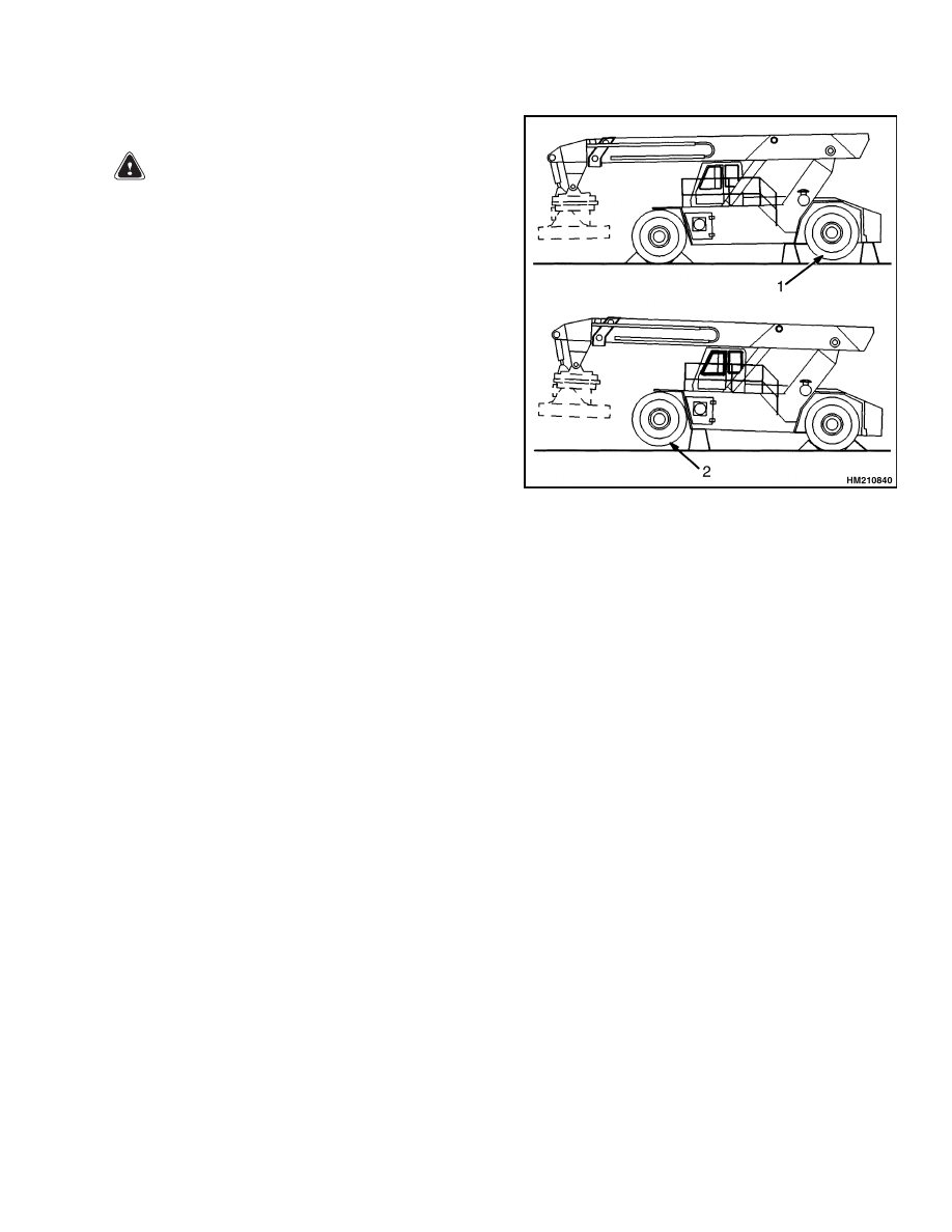
1.
Apply the parking brake.
Put blocks on both
sides (front and back) of the steering tires to pre-
vent movement of the ReachStacker. See Fig-
ure 1.
2.
Fully lower and retract the boom.
3.
Use a hydraulic jack under the side of the frame
near the front. Check that the jack has a capacity
of at least 41,000 kg (90,390 lb), equal to at least
half the weight of the ReachStacker. See the Ca-
pacity Plate.
4.
Put additional blocks under the frame behind the
drive tires. Be sure the blocks are under the
frame channels and not the tanks or compart-
ments.
2
8000 SRM 592
General
How to Raise Steering Tires
WARNING
The ReachStacker must be put on blocks for
some types of maintenance and repair. The sur-
face must be solid, even, and level when the
ReachStacker is put on blocks. Make sure that
any blocks used to support the ReachStacker
are solid, one-piece units. Do not use compo-
nent lifting points on the boom or frame to lift
the ReachStacker.
1.
Apply the parking brake.
Put blocks on both
sides (front and back) of the drive tires to prevent
movement of the ReachStacker. See Figure 1.
2.
Fully lower and retract the boom.
3.
Use a hydraulic jack to raise the steering tires.
Check that the jack has a capacity of at least
54,000 kg (119,050 lb), equal to 2/3 of the total
weight of the ReachStacker. See the Capacity
Plate.
4.
Put the jack under the steering axle or frame to
raise the ReachStacker. Put blocks under the
frame as supports for the ReachStacker.
1.
STEERING TIRES
2.
DRIVE TIRES
Figure 1. Put ReachStacker on Blocks
3
Maintenance Schedule
8000 SRM 592
Maintenance Schedule
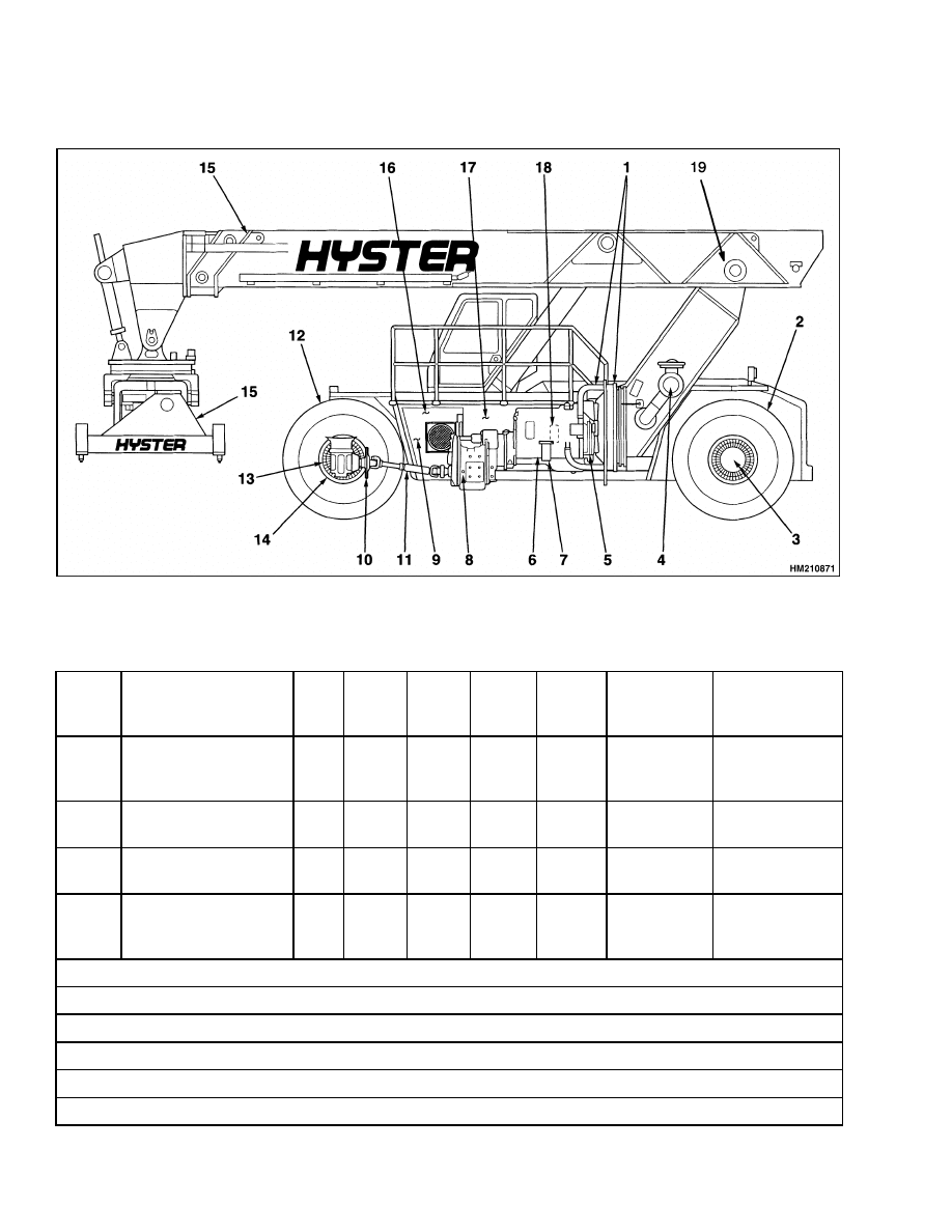
Figure 2. Maintenance and Lubrication Points
Table 1. Maintenance Schedule
Item
No.
Item
8 hr/
daily
250 hr/
1 mo
500 hr/
3 mo
1000
hr/
6 mo
2000 hr/
1 yr
Procedure
or Quantity
Specification
Fuel and Tank
Condition
X
Fuel low
400 liter
(102 gal)
Diesel No. 2
Safety Labels
X
Install as
necessary
See Parts
Manual
Check for Fuel, Oil, or
Coolant Leaks
X
Check for
leaks
Horn, Gauges, Lights,
Alarms
CIL
Check at start
and during
operation
X=Check C=Change L=Lubricate CIL=Check Indicator Light or Gauge During Operation
1
Change at first 50 hours of operation on a NEW truck.
2
Multipurpose grease with 2 to 4% molybdenum disulfide.
3
Change brake oil filter at initial 250 hours and every 1000 hours thereafter.
4
Check Krueger System every 2000 hours or every year, refer to SRM.
5
Use soap-based High Pressure Lithium grease.
4
8000 SRM 592
Maintenance Schedule
Table 1. Maintenance Schedule (Continued)
Item
No.
Item
8 hr/
daily
250 hr/
1 mo
500 hr/
3 mo
1000
hr/
6 mo
2000 hr/
1 yr
Procedure
or Quantity
Specification
Coolant Level
CIL
C
Coolant
50% water with
50% ethylene
glycol
1
Hoses
X
Check
condition
2
Tires and Tires
Pressure
X
See capacity
plate
Steering System
X
L
Steering Axle
Check
operation
3
Tie Rods and King
Pins
8 Fittings
Multipurpose
grease
2
4
Air Filter
X
CIL
C
Clean or
install new
filter
See Parts
Manual
5
Drive Belts
X
CIL
X
Check
condition
Check
tension
See Parts
Manual
See Service
Manual
6
Engine Oil
X
CIL
C
1
34 liter (9 gal)
API CE/SF or
CE/SG 0 C (32 F)
and up, SAE
20W-40;
10 C
(14 F) and up,
SAE 15W-40;
25 C ( 13 F)
to 35 C (95 F),
SAE 10W-30
7
Engine Oil Filter
C
1
1
See Parts
Manual
X=Check C=Change L=Lubricate CIL=Check Indicator Light or Gauge During Operation
1
Change at first 50 hours of operation on a NEW truck.
2
Multipurpose grease with 2 to 4% molybdenum disulfide.
3
Change brake oil filter at initial 250 hours and every 1000 hours thereafter.
4
Check Krueger System every 2000 hours or every year, refer to SRM.
5
Use soap-based High Pressure Lithium grease.
5

Maintenance Schedule
8000 SRM 592
Table 1. Maintenance Schedule (Continued)
Item
No.
Item
8 hr/
daily
250 hr/
1 mo
500 hr/
3 mo
1000
hr/
6 mo
2000 hr/
1 yr
Procedure
or Quantity
Specification
8
Transmission
Oil Level
Operation
Transmission
Oil
Filter
Transmission
Breather
CIL
X
X
C
1
X
C
1
42 liter
(11 gal)
Check
operation
Check and
clean
Hyster Part No.
336831
See Parts
Manual
9
Hydraulic System Oil
Hydraulic Filter
X
CIL
CIL
C
C
1
850 liter
(224 gal)
2
18 C (0 F) and
above
SAE 10W, API
CC or CC/SE
See Parts
Manual
X
Check
operation
10
Service Brakes and
Parking Brake
X
Check
operation
11
Drive Shaft Joints
L
3 Fittings
Multipurpose
grease
2
12
Brake System Oil
CIL
C
95 liter
(25 gal)
Hyster Part No.
336831
Wheel Nuts
X
Check torque
Drive Wheels
440 N•m
(325 lbf ft)
13
Steer Wheels
140 N•m
(103 lbf ft)
14
Drive Axle/Differential
Oil
X
C
30 liter (8 gal)
SAE 80W-90
15
Boom and Spreader
L
Lubricate as
needed
Lithium base
grease, 310-340
NLGI Grade
No. 1
X=Check C=Change L=Lubricate CIL=Check Indicator Light or Gauge During Operation
1
Change at first 50 hours of operation on a NEW truck.
2
Multipurpose grease with 2 to 4% molybdenum disulfide.
3
Change brake oil filter at initial 250 hours and every 1000 hours thereafter.
4
Check Krueger System every 2000 hours or every year, refer to SRM.
5
Use soap-based High Pressure Lithium grease.
6

8000 SRM 592
Maintenance Schedule
Table 1. Maintenance Schedule (Continued)
Item
No.
Item
8 hr/
daily
250 hr/
1 mo
500 hr/
3 mo
1000
hr/
6 mo
2000 hr/
1 yr
Procedure
or Quantity
Specification
16
Brake Oil Filter
C
3
1
See Parts
Manual
17
Battery Electrolyte
X
Check level
Pedals, Levers,
Seat and Cab Rails,
Linkages
L
Lubricate as
needed
Multipurpose
grease
2
18
Fuel Filter
Water Separator
Drain at Fuel Fil-
ter
X
C
1
1
Drain water
See Parts
Manual
19
Boom Pivot
L
5
2 Fittings
Lithium grease
5
Coolant Filter
C
1
1
See Parts
Manual
Engine Speed
Idle Speed
Governed Speed
X
Check
500 rpm
2100 rpm
Hydraulic Tank
Breather
C
Krueger Load System
X
4
Check
calibration
See 1900 SRM
642
X=Check C=Change L=Lubricate CIL=Check Indicator Light or Gauge During Operation
1
Change at first 50 hours of operation on a NEW truck.
2
Multipurpose grease with 2 to 4% molybdenum disulfide.
3
Change brake oil filter at initial 250 hours and every 1000 hours thereafter.
4
Check Krueger System every 2000 hours or every year, refer to SRM.
5
Use soap-based High Pressure Lithium grease.
7
Maintenance Procedures Every 8 Hours or Daily
8000 SRM 592
Maintenance Procedures Every 8 Hours or Daily
HOW TO MAKE CHECKS WITH ENGINE
STOPPED
WARNING
Do not operate a ReachStacker that needs re-
pairs. Report the need for repairs immediately.
If repair is necessary, put a DO NOT OPER-
ATE tag in the operator’s area. Remove the key
from the key switch.
Put ReachStacker on a level surface. Fully lower and
retract boom, stop engine, and apply parking brake.
Do all the checks outside of the engine compartment
first. Open hood and check for leaks and conditions
that are not normal. Clean any oil or fuel spills.
Make sure dirt and other materials are removed from
engine compartment.
Tires and Wheels
WARNING
Air pressure in tires can cause tire and wheel
parts to explode. The explosion of wheel parts
can cause serious injury or death.
Remove all of the air from the tires before the
tires are removed from the ReachStacker.
If the air pressure is less than 80% of the cor-
rect air pressure, the tire must be removed be-
fore air is added. Put the tire in a safety cage
when adding air pressure to the tire. Follow
the procedures described in Add Air to Tires.
When air is added to the tires, use a remote air
chuck. The person adding air must stand away
and to the side and not in front of the tire.
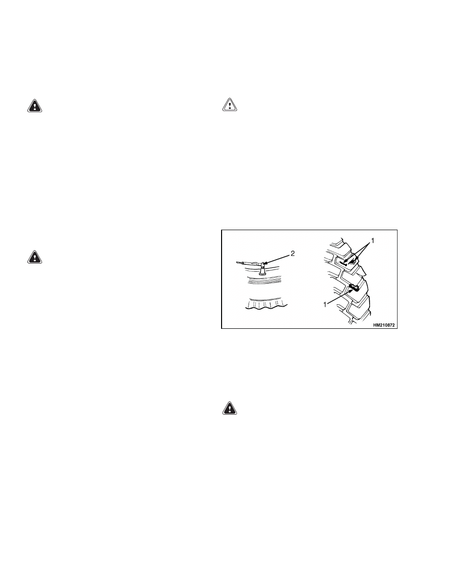
Keep tires at correct air pressure. See Figure 3. See
Capacity Plate.
Check air pressure with a gauge
when tires are cold. If it is necessary to add air to
a tire that is warm, check one of the other tires on
the same axle and add air to the tire that has low
pressure so that the air pressures are equal. The air
pressure of the warm tires must always be equal to
or greater than the specification for air pressure for
cold tires.
Check tires for damage. Inspect tread and remove
any objects that will cause damage. Check for bent
or damaged rims. Check for loose or missing parts.
Remove any wire, straps, or other material wrapped
around the axle.
CAUTION
Check all wheel nuts after 2 to 5 hours of
operation, when new ReachStackers begin
operation, and on all ReachStackers when
the wheels have been removed and installed.
Tighten nuts in a cross pattern to the correct
torque value shown in the Maintenance Sched-
ule. When the nuts stay tight for eight hours,
the interval for checking the torque can be
extended to 250 hours.
Make sure wheel nuts are tight. Tighten wheel nuts
in a cross pattern to the correct torque value shown
in the Maintenance Schedule.
1.
CHECK FOR DAMAGE (REMOVE NAILS,
GLASS, AND OTHER OBJECTS FROM TREAD)
2.
CHECK TIRE PRESSURE
Figure 3. Tires Check
Safety Labels
WARNING
Safety labels are installed on the ReachStacker
to give information about operation and possi-
ble hazards. It is important that all safety la-
bels are installed on the ReachStacker and can
be read.
Check that all safety labels are installed in the cor-
rect locations on the ReachStacker. See the Parts
Manual or the Frame section of the Service Man-
ual for the correct locations of the safety labels.
If new labels must be installed, use the following pro-
cedures:
8
8000 SRM 592
Maintenance Procedures Every 8 Hours or Daily
WARNING
Cleaning solvents can be flammable and toxic
and can cause skin irritation.
When using
cleaning solvents, always follow the recom-
mendations of the manufacturer.
1.
Make sure the surface is dry and has no oil or
grease. Do not use solvent on new paint. Clean
surface of old paint with a cleaning solvent.
2.
Remove paper from back of label. Do not touch
adhesive surface.
3.
Carefully hold label in correct position above
the surface. The label cannot be moved after it
touches the surface. Put label on surface. Make
sure all air is removed from under the label and
the corners and edges are tight.
Fuel, Oil, or Coolant Leaks Check
WARNING
All fuels are very flammable and can burn or
cause an explosion. Do not use an open flame
to check the fuel level or to check for leaks in
the fuel system. If there is a leak in the fuel sys-
tem, extra care must be used during the repair.
Do not operate the ReachStacker until a leak is
repaired.
Make a visual check for leaks on and under the
ReachStacker. If possible, find and repair leak at
source. Leaks can indicate a need for repair of dam-
aged or worn components.
Check fuel system for leaks and the condition of
parts. When fuel is added to the ReachStacker, see
the section, How to Add Fuel to ReachStacker
procedures in the Operating Manual.
Also check condition of radiator or heater hoses. Re-
place soft or cracked hoses.
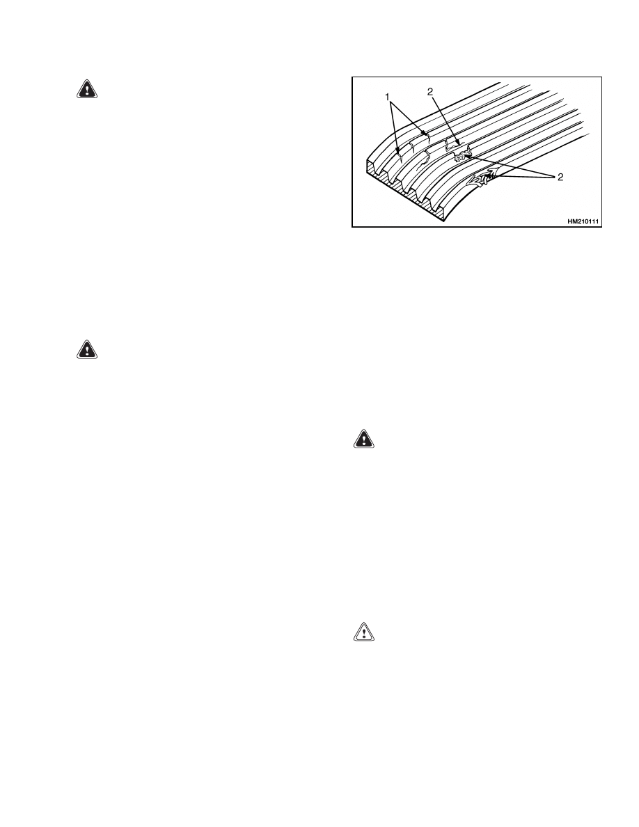
Drive Belts
Make sure key is in OFF position and engine is
stopped. Check drive belt for wear and damage. See
Figure 4. Small cracks that run across the belt are
acceptable. A drive belt with cracks that run the
length of the belt or a belt with missing pieces is not
acceptable.
Check drive belt for correct tension.
1.
ACCEPTABLE CRACKS
2.
NOT ACCEPTABLE CRACKS AND DAMAGE
Figure 4. Drive Belt
Battery
A check of the battery electrolyte level is normally
required only every 250 hours of operation. Heavy
duty or high temperature operations will require
more frequent checks. It is not necessary to check
the electrolyte level on a maintenance-free battery.
A low electrolyte level can cause the discharge in-
dicator light to come on or cause battery damage
during ReachStacker operation.
WARNING
The acid in the electrolyte can cause injury.
If the electrolyte is spilled, use water to flush
the area. Use a solution of sodium bicarbon-
ate (soda) to make the acid neutral. Acid in the
eyes must be flushed with water immediately.
Wear eye protection.
Batteries generate explosive fumes. Keep the
vents in the caps clean. Keep sparks or open
flame away from the battery area.
Do not
make sparks from the battery connections.
Disconnect the battery ground cable when
doing maintenance.
CAUTION
Disposal of batteries must meet local environ-
mental regulations.
Keep battery and cable terminals clean. Check elec-
trolyte level (unless maintenance-free battery). Keep
electrolyte level above the separators and plates. Use
distilled water. Do not fill battery more than to the
bottom of the internal filler neck.
9
Maintenance Procedures Every 8 Hours or Daily
8000 SRM 592
If battery becomes discharged and requires a booster
battery to start the engine, follow these procedures
carefully when connecting the jumper cables:
1.
Always connect positive jumper cable to positive
terminal of discharged battery and negative
jumper cable to negative terminal.
2.
Always connect jumper cable that is the ground
cable last.
3.
Always connect jumper cables to discharged bat-
tery before connecting them to booster battery.
Engine Oil
Check oil level in engine daily.
After engine has
stopped, wait one minute before checking oil level.
Keep oil at the correct level as indicated on the
dipstick. Use the correct oil as shown in the Mainte-
nance Schedule.
Drain Water from Fuel Filter
CAUTION
Disposal of lubricants and fluids must meet lo-
cal environmental regulations.
Open drain valve on bottom of fuel filter. Drain some
fuel (and any water) into a container until clean fuel
flows from filter. Close drain valve.
Hydraulic System
WARNING
At operating temperature the hydraulic oil is
HOT. Do not permit the hot oil to touch the skin
and cause a burn.
CAUTION
Do not permit dirt to enter the hydraulic sys-
tem when the oil level is checked or the filter
is changed.
Never operate the hydraulic pump without oil
in the hydraulic system. The operation of the
hydraulic pump without oil will damage the
pump.
The oil level gauge is on the outside of the hydraulic
tank. Keep oil level between the two marks when all
of the cylinders are retracted.
Check hydraulic system for leaks and damaged or
loose components.
Cooling System
WARNING
DO NOT remove the cap from the auxiliary
coolant reservoir when the engine is hot.
When the cap is removed, the pressure is re-
leased from the system. If the system is hot,
the steam and boiling coolant can cause burns.
Check coolant level at auxiliary coolant reservoir
near radiator. If coolant is added, use the correct
mixture of water and ethylene glycol shown in the
Maintenance Schedule.
WARNING
Compressed air can move particles so that they
cause injury to the user or to other personnel.
Make sure that the path of the compressed air
is away from all personnel.
Wear protective
goggles or a face shield to prevent injury to the
eyes.
Check radiator fins. Clean radiator with compressed
air or water as needed.
Air Filter
Check indicator light for air filter during operation.
When the amber light comes on, filters are dirty.
Clean or install new air filter elements as necessary.
Use compressed air to clean filter elements.
Air
pressure must be less than 210 kPa (30 psi). Apply
air from inside to outside of filter element.
Inspect filter element. Put a bright light inside
filter element and look for holes or other damage. If
filter element is damaged, install new filter element.
Use a cloth with solvent to clean inside of canister
before filter element is installed.
Boom and Spreader
1.
Inspect boom sections for cracks and wear.
2.
Inspect spreader sections for cracks and wear.
3.
Replace any damaged or broken parts.
10

8000 SRM 592
Maintenance Procedures Every 8 Hours or Daily
HOW TO MAKE CHECKS WITH ENGINE
RUNNING
WARNING
Exhaust from internal combustion engines
contains carbon monoxide and other harmful
chemicals.
Carbon monoxide is a colorless,
odorless poison and can cause unconscious-
ness or death without warning.
Long term
exposure to exhaust or chemicals in the ex-
haust can cause cancer, birth defects, and
other reproductive harm.
Avoid exposure to engine exhaust:
• Do not use diesel engines indoors where soot
can accumulate.
• If engines are operated in confined spaces
maintain adequate ventilation or vent ex-
haust to the outside. Do not exceed applica-
ble air contaminant limits.
• Follow
the
inspection
and
maintenance
schedule and procedures in this manual. Do
not alter exhaust, ignition, or fuel systems.
Make sure that the area around the ReachStacker
is clear before starting the engine or making any
checks of the operation. Be careful when making the
checks. If the ReachStacker is stationary during a
check, apply parking brake and put transmission in
NEUTRAL. Make checks carefully.
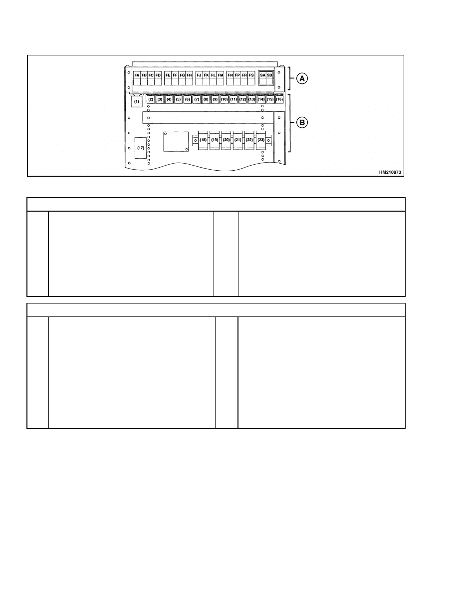
Gauges, Indicator Lights, Horn, Fuses,
and Relays
Check operation of horn. Push on start switch and
turn key switch to ON position. Check all gauges and
indicator lights for correct operation. See Figure 5.
start engine. Check gauges and indicator lights for
correct operation as described in the Operating
Manual. If any indicator lights or gauges do not
operate correctly, turn key switch OFF and check
thermal switches. Push on switch to reset circuit.
The fuse panel is in the battery compartment.
Control Levers and Pedals
Check that controls for transmission, boom, and
spreader operate as described in the Operating
Manual.
Check that pedals operate correctly as
described in the Operating Manual.
Electrical System
Check voltmeter and discharge indicator light during
operation. The discharge indicator light can come on
during operation if the drive belt does not have the
correct tension. Also check condition of battery.
Transmission Oil
Check indicator lights for transmission during oper-
ation. There are indicator lights for the oil filter, oil
pressure, and oil temperature of the transmission.
The amber light for the oil filter comes on when the
filter is dirty. The red light for the oil pressure is on
when the oil pressure is too low for correct operation.
The red light for the oil temperature is on when the
temperature is too high for correct operation. Make a
visual check of transmission and check transmission
oil level.
Apply parking brake. Check oil level in transmission
when engine is running at idle speed and transmis-
sion oil is at operating temperature. Put direction
control lever in NEUTRAL position. Use correct oil
shown in the Maintenance Schedule. Keep oil level
at full level.
Steering System
WARNING
The ReachStacker has hydraulic power steer-
ing. The steering can be difficult when the en-
gine is not running.
Make sure steering system operates smoothly and
provides good steering control.
Service Brakes
Check operation of service brakes. Push on brake
pedal. The service brakes must be applied before
brake pedal reaches floor plate. The pedal must stop
must apply equally to each side of the drive and steer
wheels.
The service brakes must not pull Reach-
Stacker to either side of the direction of travel when
they are applied.
11
Maintenance Procedures Every 8 Hours or Daily
8000 SRM 592
A. THERMAL SWITCHES
B. RELAYS
Thermal Switches
FA.
FB.
FC.
FD.
FE.
FF.
FG.
FH.
FJ.
Not Used
start Circuit/Horn, 10A
Rotating Beacon, 10A
Lights, 10A
Flasher/Brakes/Trans., 9A
Stop/Reverse, 7A
start, 7A
Brake Oil Cooler, 7A
Emergency Stop - Hydraulic Oil Cooler, 9A
FK.
FL.
FM.
FN.
FP.
FR.
FS.
SA.
SB.
Wipers-Washer-Sliding Cab
Kruger/Spreader, 9A
Attachment
Boom Stops - Joystick
Attachment Controls
20
″
-40
″
Work Lights, 12A
Work Lights
Transmission Override Switch (APC-100)
Transmission Auto/Manual Switch
Relays
1.
2.
3.
4.
5.
6.
7.
8.
9.
10.
11.
12.
start
start Solenoid
Horn
Rotating Beacon
Flasher
Reverse Alarm
start Permission
Twist Lock
20
″
Work Lights
40
″
Work Lights
Truck Work Lights
Flasher Relay Backup Lights
13.
14.
15.
16.
17.
18.
19.
20.
21.
22.
23
Rear Work Lights
Transmission
Rear Work Lights
Air Conditioning
Main Relay
Boom Cutout
Boom Cutout
Transmission
Transmission
Boom Cutout
Boom Cutout
Figure 5. Thermal Switch and Relay Panel
Parking Brake
Check operation of parking brake.
The parking
brake, when in good condition and operating cor-
rectly, will hold a ReachStacker with a capacity
load on a 15% grade. A 15% grade is a slope that
increases 1.5 m in 10 m (1.5 ft in 10 ft).
Engine Oil
Check gauge and indicator light during operation.
There is a gauge and indicator light on the instru-
ment panel for the engine oil pressure. The red light
for the indicator is on when the engine oil pressure is
too low for correct operation. Stop engine and check
oil level.
12
8000 SRM 592
Maintenance Procedures Every 250 Hours or Monthly
Cooling System
Check coolant temperature gauge and indicator light
for coolant level during operation. Do not operate ve-
hicle when temperature is above 100 C (212 F). The
red light is on when the coolant level is too low.
Hydraulic System
Check hydraulic oil filter light during operation. The
amber light is on when the filters are dirty.
Boom and Spreader Operation
WARNING
Lower and retract the boom completely. Never
allow any person under a raised boom or
spreader. Do not put any part of your body
in or through the lift mechanism unless all
parts of the boom and spreader are completely
lowered and the engine is STOPPED.
Do not try to find hydraulic leaks by putting
hands on pressurized hydraulic components.
Hydraulic oil can be injected into the body by
the pressure.
Do the following checks and inspections:
1.
Check for leaks in hydraulic system. Check con-
dition of hydraulic hoses and tubes.
2.
Slowly raise and lower boom several times with-
out a load. Extend and retract boom at least once.
The boom must raise and lower smoothly.
3.
Check that controls for boom and spreader oper-
ate functions correctly. See symbols by each of
the controls.
Maintenance Procedures Every 250 Hours or Monthly
NOTE: Do these procedures in addition to the 8-hour
checks.
ENGINE AND OIL FILTER
CAUTION
Disposal of lubricants and fluids must meet lo-
cal environmental regulations.
NOTE: Change oil and filter for engine after first
50 hours on a new ReachStacker.
After the first
50 hours, change oil and filter every 250 hours or
monthly.
Change oil filter and engine oil at the same time. Use
correct oil according to the Maintenance Schedule.
Fill filter with oil before installing it on engine. After
changing filter and oil, start engine, and check area
around filter for leaks. Check oil level at dipstick
that is on the left-hand side of engine.
BRAKE SYSTEM OIL
Check oil level in tank for brake system oil.
BATTERY
See procedures under Maintenance Procedures Ev-
ery 8 Hours or Daily.
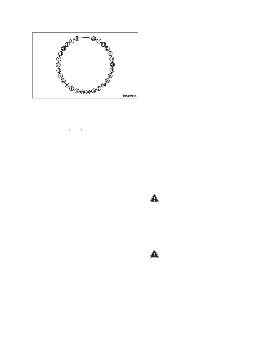
WHEEL NUTS
Check torque of wheel nuts in the sequence shown in
Figure 12. The correct torque value is in the Mainte-
nance Schedule.
STEERING AXLE TIE RODS
Lubricate grease fittings on steering tie rods with
multipurpose grease.
DRIVE SHAFT JOINTS
Lubricate grease fittings on drive shafts.
DRIVE AXLE AND DIFFERENTIAL OIL
The drive axle and differential use the same oil sup-
ply. The oil level in the drive axle is correct when the
oil is even with the plug in the center of the hub cover.
The oil level in the differential is correct when the oil
is even with the plug in the front of the housing. Add
correct oil as specified in the Maintenance Schedule.
GENERAL LUBRICATION
Lubricate any linkages, rod ends, levers, cab rails,
hinges, and seat rails with engine oil.
13
Maintenance Procedures Every 500 Hours or 3 Months
8000 SRM 592
Maintenance Procedures Every 500 Hours or 3 Months
NOTE: Do these procedures in addition to the 250-
hour checks.
HYDRAULIC FILTER
CAUTION
Disposal of lubricants and fluids must meet lo-
cal environmental regulations.
Change elements in hydraulic filters. Install new fil-
ter elements, then install and tighten filter heads.
FUEL FILTER/WATER SEPARATOR
The fuel filter/water separator is installed on the
right side of the engine. When replacing the spin-on
filter element, fill new filter with clean fuel. Install
filter and tighten it by hand. Start engine and check
for leaks.
TRANSMISSION FILTER
CAUTION
Disposal of lubricants and fluids must meet lo-
cal environmental regulations.
NOTE: Change oil filter for transmission after first
50 hours on new ReachStackers. After the first 50
hours, change filter every 500 hours or every three
months of operation.
Remove and install new oil filter.
COOLANT FILTER
WARNING
DO NOT remove the cap from the auxiliary
coolant reservoir when the engine is hot.
When the cap is removed, the pressure is re-
leased from the system. If the system is hot,
the steam and boiling coolant can cause burns.
CAUTION
Disposal of lubricants and fluids must meet lo-
cal environmental regulations.
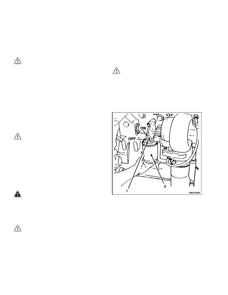
Remove cap at auxiliary coolant reservoir and close
shutoff valve at filter.
See Figure 6. Clean area
around filter head. Remove and discard coolant fil-
ter. Apply clean engine oil to gasket of new filter. In-
stall new filter and turn filter until gasket touches,
then tighten it 1/2 to 3/4 turn.
CAUTION
Do not start the engine with the coolant shutoff
valve in the closed (OFF) position. The engine
can be damaged when running with the valve
closed.
Install cap on auxiliary coolant reservoir and open
shutoff valve. Start engine. Check area around filter
for leaks.
1.
SHUTOFF VALVE
2.
COOLANT FILTER
Figure 6. Coolant Filter
14
8000 SRM 592
Maintenance Procedures Every 1000 Hours or 6 Months
Maintenance Procedures Every 1000 Hours or 6 Months
NOTE: Do these procedures in addition to the 500-
hour checks.
TRANSMISSION OIL
CAUTION
Disposal of lubricants and fluids must meet lo-
cal environmental regulations.
NOTE: Change oil for transmission after first 50
hours on new ReachStackers.
After the first 50
hours, change the oil every 1000 hours or every six
months of operation.
When filling transmission, start by putting in 19 liter
(5.0 gal) of correct oil. Start engine and let it run for
at least five minutes. Apply brakes and shift range
selector lever through all ranges. Fill transmission to
full mark. Check oil level with engine at idle speed.
Change oil for transmission. Use oil specified in the
Maintenance Schedule.
BRAKE SYSTEM FILTER
CAUTION
Disposal of lubricants and fluids must meet lo-
cal environmental regulations.
Remove and install new oil filter.
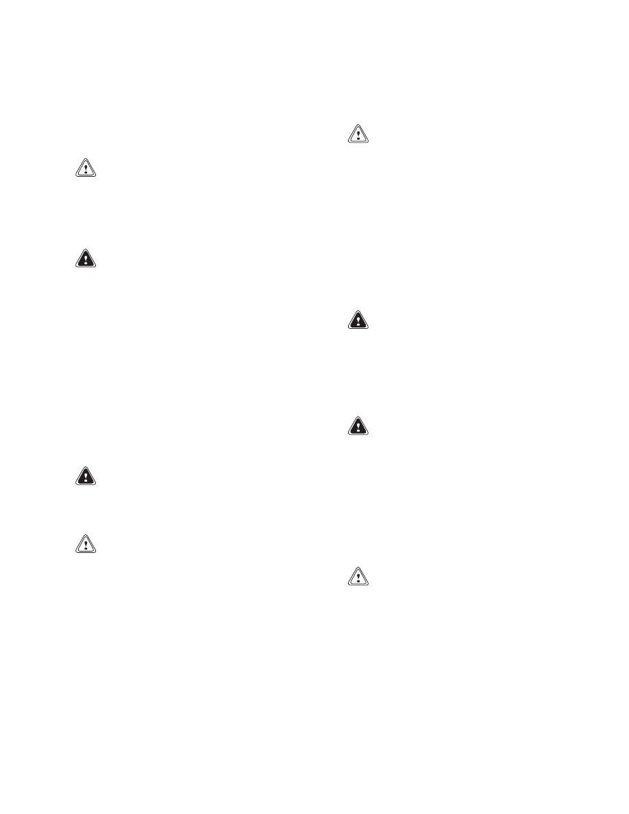
DISC BRAKES
There are disc brake assemblies at each steer wheel.
There is also a disc brake assembly installed on the
differential housing. The small brake caliper is for
the parking brake. The large caliper is for the ser-
vice brake system. Inspect disc brake assembly ev-
ery 1000 hours.
Cleaning Procedures
WARNING
Brake linings can contain dangerous fibers.
Breathing the dust from brake linings is a can-
cer or lung disease hazard. Do not create dust!
Do not clean brake parts with compressed
air or by brushing.
Use vacuum equipment
approved for dangerous fibers or follow the
cleaning procedure in this section.
Do not sand, grind, chisel, hammer, or change
linings in any way that will create dust. Any
changes to brake linings must be done in a re-
stricted area with special ventilation. Protec-
tive clothing and a respirator must be used.
1.
Do not release dust from brake linings into air
when checking brakes.
2.
Use a solvent to wet the lining dust on the parts
of the brake. If a solvent spray is used, do not
create dust with spray.
3.
When lining dust is wet, clean parts. Put any
cloth or towels in plastic bag or airtight container
while they are still wet. Put a DANGEROUS
FIBERS warning label on plastic bag or airtight
container.
4.
Any cleaning cloths that will be washed must be
cleaned so that fibers are not released into the
air.
Inspect
Inspect brake lining and parts of brake assembly for
wear or damage. If brake linings are worn or dam-
aged, they must be replaced. Brake linings must be
replaced in complete sets. Inspect brake rotors for
wear or damage.
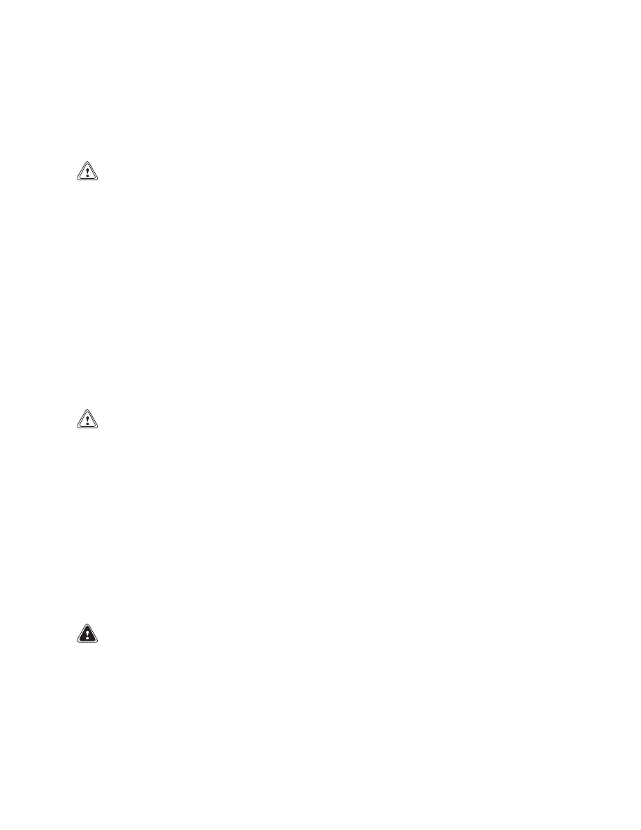
1.
Inspect brake linings as shown in Figure 7. In-
spect brake rotor as shown in Figure 8.
2.
Check calipers for leaks. See Figure 9.
15
Maintenance Procedures Every 1000 Hours or 6 Months
8000 SRM 592
1.
MINIMUM LINING (PAD) THICKNESS 3.0 mm
(0.12 in.) FROM BACK PLATE
2.
LINING
3.
BACK PLATE
4.
UNEVEN LINING WEAR
5.
CRACKED LININGS
6.
OIL OR GREASE ON LININGS
Figure 7. Inspect Brake Parts
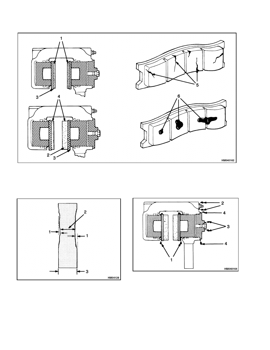
1.
MAXIMUM ROTOR WEAR 1.5 mm (0.06 in.)
2.
MINIMUM ROTOR THICKNESS 17.0 mm
(0.67 in.)
3.
ROTOR THICKNESS 20.07 mm (0.80 in.)
Figure 8. Inspect Rotor for Parking Brake and
Auxiliary Calipers
1.
LEAKS AT PISTON
2.
LEAKS AT SCREWS
3.
LEAKS AT INLET FITTING
4.
LEAKS AT CYLINDER HEAD
Figure 9. Leaks Check
16
8000 SRM 592
Maintenance Procedures Every 2000 Hours or Annually
Maintenance Procedures Every 2000 Hours or Annually
NOTE: Do these procedures in addition to the 1000-
hour checks.
ENGINE COOLANT
CAUTION
Disposal of lubricants and fluids must meet lo-
cal environmental regulations.
1.
Change coolant in cooling system. Put Reach-
Stacker on level surface. Stop engine.
WARNING
If the coolant is hot, do not permit the coolant
to touch the skin and cause a burn.
2.
Remove drain plugs or open drain valves. Re-
move cap from auxiliary coolant reservoir. Flush
cooling system.
Check hoses and fittings as
needed.
3.
Install drain plugs or close drain valves. Fill cool-
ing system with correct coolant (50% water and
50% ethylene glycol).
4.
Install cap on auxiliary coolant reservoir. Start
engine. Check for leaks.
HYDRAULIC OIL
WARNING
At operating temperature the hydraulic oil is
HOT. Do not permit the oil to touch the skin and
cause a burn.
CAUTION
Disposal of lubricants and fluids must meet lo-
cal environmental regulations.
Change oil filters for hydraulic system at first 50
hours of operation on new ReachStackers. After the
first 50 hours, change filters every 2000 hours or an-
nually.
Change Hydraulic Oil
CAUTION
Do not permit dirt to enter the hydraulic sys-
tem when the oil is checked or the filters are
changed.
1.
Put ReachStacker on level surface and retract
and lower boom completely. Put container under
hydraulic tank. Remove drain plug to drain oil.
2.
When hydraulic oil has drained, install drain
plug. Fill hydraulic tank with correct oil. Oper-
ate system and check for leaks.
Hydraulic Tank Breather
WARNING
Compressed air can move particles so they
cause injury to the user or to other personnel.
Make sure the path of the compressed air is
away from all personnel. Wear protective gog-
gles or a face shield to prevent injury to the
eyes.
WARNING
Cleaning solvents can be flammable and toxic
and can cause skin irritation.
When using
cleaning solvents, always follow the recom-
mendations of the manufacturer.
Remove hydraulic tank breather from cover and
clean in solvent. Dry breather with compressed air
and install it on cover.
DRIVE AXLE AND DIFFERENTIAL OIL
CAUTION
Disposal of lubricants and fluids must meet lo-
cal environmental regulations.
Change oil for differential and drive axle. To drain
oil, remove plugs from planetary covers and plug at
the bottom of the differential housing. Fill drive axle
with oil specified in the Maintenance Schedule. After
filling, operate ReachStacker to make sure oil level is
even. Check oil level again and check for leaks.
17
Wheels and Tires
8000 SRM 592
Wheels and Tires
REMOVE WHEELS
WARNING
The type of tire and tire pressure are shown
on the Capacity Plate. Make sure the Capac-
ity Plate is correct for the type of tires on the
ReachStacker.
WARNING
Wheels must be changed and tires repaired by
trained personnel only.
Always wear safety glasses.
Completely remove the air pressure from
the tire before it is removed from the Reach-
Stacker. If dual wheels are installed, remove
air from both tires. Air pressure in the tires
can cause the tire and wheel parts to explode,
causing serious injury or death.
1.
Raise the ReachStacker as described in How to
Put ReachStacker on Blocks in this section.
2.
Remove air from tire. Remove valve core to make
sure all air pressure is out of tire. See Figure 10.
Push a wire through the valve stem to make sure
that the stem does not have a restriction. When
dual tires are installed, remove air pressure from
both tires.
3.
Remove wheel nuts and rim clamps, then remove
wheel from ReachStacker. Tires and wheels are
heavy.
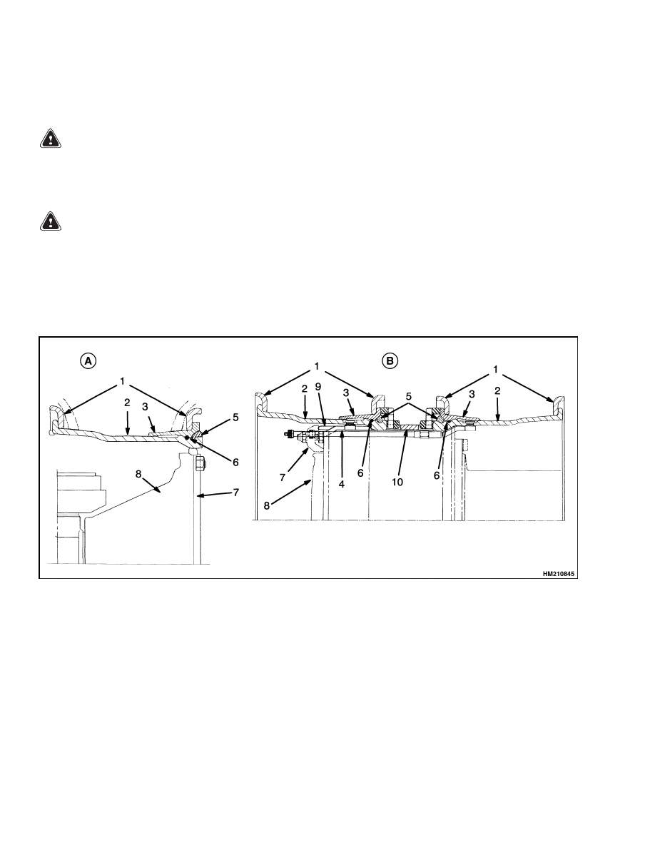
A. STEER WHEEL
B. DRIVE WHEELS
1.
SIDE FLANGE
2.
WHEEL RIM
3.
FLANGE SEAT
4.
VALVE STEM
5.
LOCK RING
6.
O-RING
7.
RIM CLAMP
8.
HUB
9.
WEDGE BAND
10. SPACER
Figure 10. Wheel Arrangements
18
8000 SRM 592
Wheels and Tires
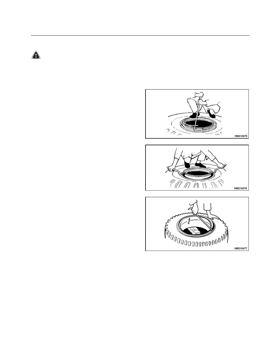
REMOVE WHEEL FROM TIRE
WARNING
Make sure all of the air pressure is removed from the tire before a wheel is disassembled. Air
pressure in the tires can cause the tire and wheel parts to explode, causing serious injury or death.
Keep tire tools in firm contact with wheels parts. If the tool slips, it can move with enough force
to cause serious injury.
STEP 1.
Loosen tire from side flange. Remove lock ring.
STEP 2.
Push flange seat downward and remove seal ring.
STEP 3.
Remove side flange and flange seat.
19
Wheels and Tires
8000 SRM 592
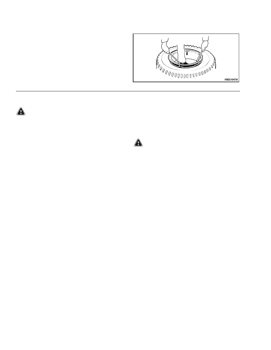
STEP 4.
Loosen tire from other side of wheel rim. Remove side
flange and seal ring as necessary. Remove rim from
tire.
INSTALL TIRE ON WHEEL
WARNING
Damage to the tire and wheel assembly and in-
jury or death can occur if you do not do the fol-
lowing procedures:
• Clean and inspect all parts of the wheel be-
fore installing the tire.
• DO NOT use any damaged or repaired wheel
parts.
• Make sure all parts of the wheel are the cor-
rect parts for that wheel assembly.
• DO NOT mix parts between different types or
manufacturers of wheels.
• DO NOT mix types of tires, type of tire tread,
or wheel assemblies of different manufactur-
ers on any one ReachStacker.
Do not use a steel hammer on the wheel. Use
a rubber, lead, plastic, or brass hammer to put
parts together. Make sure that the lock ring is
in the correct position. The ends of the lock
ring must not touch.
NOTE: When assembling the wheels, see Figure 10.
There are several kinds of wheels used on Reach-
Stackers.
1.
Clean and inspect all parts of wheel. If wheel has
rust or corrosion, remove loose rust and corrosion
and paint the parts.
WARNING
Do not lubricate the tire bead with antifreeze
or petroleum-based liquid. Vapors from these
liquids can cause an explosion when air pres-
sure is added or when the tire is in use.
2.
Apply rubber lubricant or soap solution to tire
bead and tube.
3.
Make sure the rim is the correct size for the tire.
Lubricate the part of the wheel that contacts the
bead.
4.
Install wheel in tire as shown in Install Wheel in
Tire.
20
8000 SRM 592
Wheels and Tires
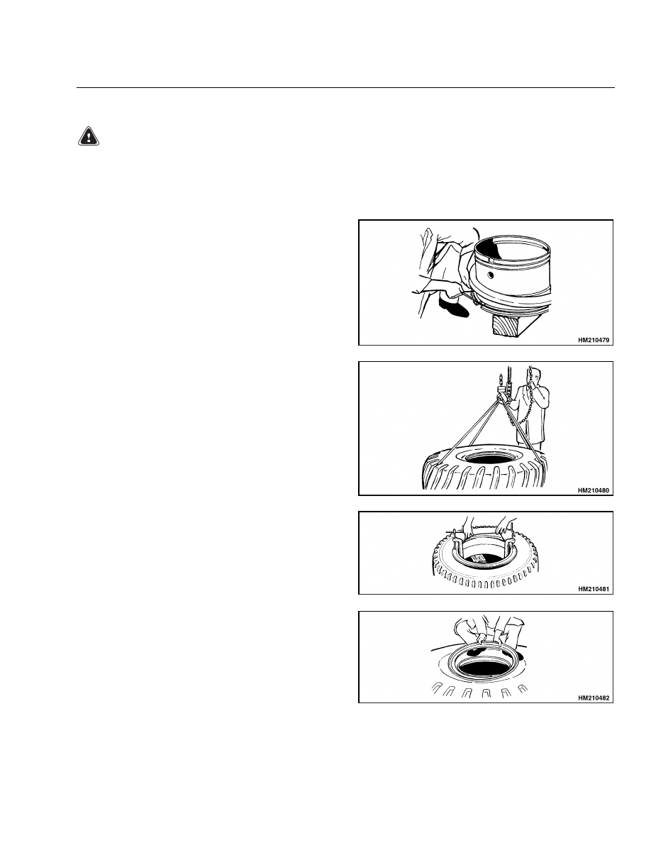
INSTALL WHEEL IN TIRE
WARNING
Make sure all air pressure is removed from the tire before a wheel is disassembled. Air pressure
in the tires can cause the tire and wheel parts to explode, causing serious injury or death.
Keep tire tools in firm contact with wheels parts. If the tool slips, it can move with enough force
to cause serious injury.
STEP 1.
Put rim on blocks. Install side flange. Make sure side
flange is engaged with rim.
STEP 2.
Install valve stem in rim. Install tire on rim.
STEP 3.
Install flange seat and seal ring.
STEP 4.
Install side flange.
21
Wheels and Tires
8000 SRM 592
STEP 5.
Install lock ring. Make sure all parts are correctly
aligned. When correctly installed, there will be a 13
to 25 mm (0.5 to 1.0 in.) clearance between ends of
side ring and/or lock ring. Add air pressure to the tire
as described in Add Air to Tires.
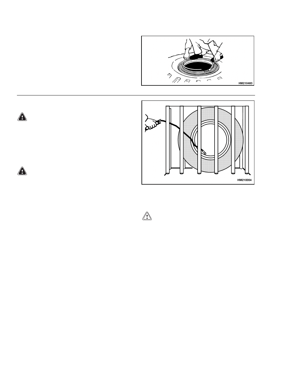
ADD AIR TO TIRES
WARNING
Add air pressure to the tires only in a safety
cage. Inspect the safety cage for damage before
use. When air pressure is added to the tire, use
a chuck that fastens onto the valve stem. Make
sure there is enough air hose to permit the op-
erator to stand away from the safety cage when
air pressure is added to the tire.
WARNING
Do not sit or stand by the safety cage. Do not
use a hammer to try and correct the position of
the side flange or lock ring when the tire has
air pressure greater than 20 kPa (3.0 psi).
1.
Put tire in a safety cage. See Figure 11.
2.
Add 20 kPa (3.0 psi) air pressure to tire.
3.
Check that all wheel parts are correctly installed.
Hit lock ring to make sure it is in the seat.
4.
If installation is correct, add air to the tire to the
correct pressure. (See capacity plate.)
5.
Check that all wheel parts are correctly installed.
If installation is not correct, remove all air pres-
sure from the tire.
Remove the valve core to
make sure all air pressure has been removed and
then make adjustments.
Figure 11. Add Air to Tires
INSTALL WHEELS
CAUTION
When the wheels have been installed, check
all wheel nuts after 2 to 5 hours of operation.
Tighten the nuts to the correct torque. When
the nuts stay tight for eight hours, the interval
for checking can be extended to 250 hours.
Install wheel(s) on hub. Tighten nuts in three stages.
Use the sequence shown in Figure 12. First, tighten
nuts to 35 N•m (26 lbf ft), then tighten to 100 N•m
(74 lbf ft). Finally, tighten nuts to the torque value
as shown in the Maintenance Schedule.
22
8000 SRM 592
Wheels and Tires
Figure 12. Wheel Nut Tightening Sequence
HOW TO STORE REACHSTACKER
These storage procedures are for conditions and tem-
peratures above 0 C (32 F). Adjust these procedures
for local conditions and any changes in conditions
during storage. The following conditions also affect
storage preparations:
• Short-term storage is from 1 to 6 months. Long-
term storage is over 6 months.
• Storage Location. A ReachStacker stored indoors
will not require as much external protection as a
ReachStacker stored outdoors.
Short-Term Storage
Do the following steps to prepare the ReachStacker
for storage from 1 to 6 months:
1.
Check lubricant and fluid levels. Completely fill
fuel tank. Make sure coolant mixture will protect
cooling system and engine to lowest temperature
expected during storage. Make sure all caps and
dipsticks are installed correctly.
2.
Fully lower and retract boom. Apply a thin coat
of engine oil to cylinder rods.
3.
Check that all switches and accessories are in the
OFF position.
4.
If the ReachStacker must be left on an incline,
put blocks on the down hill side of the wheels so
the ReachStacker cannot move - do not use the
parking brake.
5.
Disconnect battery cables from batteries. Apply
a protective coat to the cable connectors and bat-
tery terminals to prevent corrosion.
6.
Check tire pressure. Make sure tires have the
correct pressure (see the capacity plate).
7.
Clean engine compartment to prevent corrosion.
8.
If the ReachStacker is not stored in a shelter, put
a cover over the ReachStacker to prevent damage
from the weather. In wet conditions, a cover will
not prevent corrosion to a ReachStacker that is in
long-term storage outside of a dry storage area.
Long-Term Storage
Do the following steps to prepare the ReachStacker
for storage for 6 months or longer:
1.
Complete all short-term storage procedures.
2.
Wrap or cover all exterior lights, radiator grill,
and air vents with a moisture barrier cover. Use
tape to hold the covers in position.
3.
Remove batteries from ReachStacker. Store bat-
teries in an approved space. Be sure to follow
local regulations. Batteries that are stored for
long periods can become damaged. A recommen-
dation is that the batteries be used in service if
possible.
4.
Spray preservative coating on external surfaces
and frame.
HOW TO MOVE A REACHSTACKER ON A
TRANSPORT
WARNING
Stay a safe distance from the edge of docks,
ramps, platforms, and other similar working
surfaces.
Watch the "tail swing." Remember
when traveling in the forward direction and
the steering wheel is turned to move the
ReachStacker away from the edge of the dock,
the rear will swing toward the edge. This can
cause the ReachStacker to fall off the dock.
WARNING
IF THE REACHSTACKER FALLS OFF THE
DOCK, DO NOT JUMP OFF! HOLD FIRMLY
TO STEERING WHEEL, BRACE YOUR FEET,
AND LEAN FORWARD AND AWAY FROM THE
POINT OF IMPACT.
Before transporting the ReachStacker, check the se-
lected route to make sure there is enough clearance
for it, as loaded on the transport vehicle. Bridges,
overpasses, power lines, and natural barriers can
prevent clearance.
Removal of the boom and/or
spreader may be necessary.
23
Wheels and Tires
8000 SRM 592
If a trailer is the method of transportation, use blocks
in front and back of the trailer tires to prevent move-
ment of the trailer when the ReachStacker is loaded
and unloaded. If a loading ramp is used, make sure
that the ramp is the correct design and capacity.
Lift the ReachStacker only at the designated lifting
points.
Loading
If the boom and/or spreader must be removed for
transport of the ReachStacker, see the Service Man-
ual for removal procedures.
The operator must never leave a ReachStacker in
a condition so that it can cause damage and injury.
When a ReachStacker is loaded on a transport, do
these operations:
1.
Apply parking brake.
2.
Fully lower and retract boom.
3.
Put direction control lever for transmission in
NEUTRAL.
4.
Turn key switch OFF to stop engine. Check that
all switches and accessories are turned OFF.
5.
To prevent any movement, put blocks in front
and back of the ReachStacker tires. Make sure
blocks are attached to the load surface.
WARNING
The straps or chains used to fasten the Reach-
Stacker to the transport must be directly con-
nected to the ReachStacker frame or to a com-
ponent (drive axle) that is solidly attached to
the frame. Do not fasten a strap or chain to the
boom or spreader to hold the ReachStacker on
the transport.
CAUTION
Make sure that any straps or chains used to fas-
ten the ReachStacker to the transport do not
contact any tubes, hoses, hydraulic cylinders,
or other parts of the truck that are easily dam-
aged.
If the ReachStacker is transported in severe weather
or any other condition that can damage it, cover the
ReachStacker. Check that the protective cover that is
designed for the application and is securely fastened.
Unloading
If components normally attached to the Reach-
Stacker were removed for transport, see the Service
Manual for installation procedures.
1.
If used, remove any protective cover.
2.
Make sure parking brake is applied.
3.
Disconnect straps or chains.
4.
Remove wheel blocks.
5.
Check that all switches and accessories are
turned OFF.
6.
Unload ReachStacker.
PREPARATION FOR USE
After transporting or storage, the ReachStacker
must be prepared for operation. Correct all prob-
lems before using the ReachStacker, see Service
Manual procedures.
Preparation After Transport
1.
Complete unloading procedures.
2.
Inspect ReachStacker for damage and missing
parts.
3.
Do the procedures in How to Make Checks With
Engine Stopped.
Preparation After Storage
1.
Remove all tape, covers, and preservation mate-
rials.
2.
Check ReachStacker for damage and missing
components.
Repair damage and/or replace
missing parts.
NOTE: If ReachStacker has been stored longer than
one year, all lubricants and fluids must be drained
and replaced. Refer to Periodic Maintenance sec-
tion.
3.
Clean battery cables and terminals. Check bat-
tery voltage. If voltage is not correct, charge bat-
tery. Connect battery cables to battery.
4.
Do the procedures in Maintenance Procedures
Every 8 Hours or Daily.
24


TECHNICAL PUBLICATIONS
8000 SRM 592
3/05 (6/00)(4/00)(6/98)(2/96) Printed in United Kingdom
Document Outline
- toc
- Periodic Maintenance
- Safety Precautions Maintenance and Repair
- General
- Maintenance Schedule
- Maintenance Procedures Every 8 Hours or Daily
- Maintenance Procedures Every 250 Hours or Monthly
- Maintenance Procedures Every 500 Hours or 3 Months
- Maintenance Procedures Every 1000 Hours or 6 Months
- Maintenance Procedures Every 2000 Hours or Annually
- Wheels and Tires
- tables
Wyszukiwarka
Podobne podstrony:
897875 8000SRM0616 (03 2005) UK EN
1495208 8000SRM0949 (03 2005) UK EN
1510478 8000SRM0988 (06 2005) UK EN
897953 1600SRM0639 (03 2005) UK EN
1598459 1900SRM1213 (03 2005) UK EN
897956 1900SRM0642 (03 2005) UK EN
897457 8000SRM0488 (03 1992) UK EN
897963 4500SRM0649 (03 2005) UK EN
1566279 8000SRM1155 (02 2005) UK EN
1573930 0600SRM1172 (03 2005) UK EN
1586985 2200SRM1178 (03 2005) UK EN
897345 1400SRM0413 (03 2005) UK EN
1531815 1800SRM1040 (03 2005) UK EN
899782 2000SRM0077 (03 2005) UK EN
1580526 8000SRM1151 (05 2005) UK EN
więcej podobnych podstron