AUXILIARY BRAKE
CALIPER
RS45-27IH, RS45-30CH, RS46-30IH, RS46-33CH, RS46-33IH,
RS46-36CH Up to 1528, 1530, 1531, and 1532 [A222];
H20.00-32.00F, H28.00F-16CH (H440, H550, H620,
H700F, FS) [E008]; H36.00-48.00E (H800-1050E) [D117];
H36.00-48.00E-16CH (H800-1050E-16CH) [D117]
PART NO. 1531815
1800 SRM 1040

SAFETY PRECAUTIONS
MAINTENANCE AND REPAIR
• When lifting parts or assemblies, make sure all slings, chains, or cables are correctly
fastened, and that the load being lifted is balanced. Make sure the crane, cables, and
chains have the capacity to support the weight of the load.
• Do not lift heavy parts by hand, use a lifting mechanism.
• Wear safety glasses.
• DISCONNECT THE BATTERY CONNECTOR before doing any maintenance or repair
on electric lift trucks. Disconnect the battery ground cable on internal combustion lift
trucks.
• Always use correct blocks to prevent the unit from rolling or falling. See HOW TO PUT
THE LIFT TRUCK ON BLOCKS in the Operating Manual or the Periodic Mainte-
nance section.
• Keep the unit clean and the working area clean and orderly.
• Use the correct tools for the job.
• Keep the tools clean and in good condition.
• Always use HYSTER APPROVED parts when making repairs. Replacement parts
must meet or exceed the specifications of the original equipment manufacturer.
• Make sure all nuts, bolts, snap rings, and other fastening devices are removed before
using force to remove parts.
• Always fasten a DO NOT OPERATE tag to the controls of the unit when making repairs,
or if the unit needs repairs.
• Be sure to follow the WARNING and CAUTION notes in the instructions.
• Gasoline, Liquid Petroleum Gas (LPG), Compressed Natural Gas (CNG), and Diesel fuel
are flammable. Be sure to follow the necessary safety precautions when handling these
fuels and when working on these fuel systems.
• Batteries generate flammable gas when they are being charged. Keep fire and sparks
away from the area. Make sure the area is well ventilated.
NOTE: The following symbols and words indicate safety information in this
manual:
WARNING
Indicates a condition that can cause immediate death or injury!
CAUTION
Indicates a condition that can cause property damage!

Auxiliary Brake Caliper
Table of Contents
TABLE OF CONTENTS
General ...............................................................................................................................................................
Description and Operation ................................................................................................................................
Auxiliary Brake Caliper Repair ........................................................................................................................
Brake Linings ................................................................................................................................................
Remove.......................................................................................................................................................
Clean and Inspect......................................................................................................................................
Install .........................................................................................................................................................
Auxiliary Caliper ...........................................................................................................................................
Remove.......................................................................................................................................................
Disassemble ...............................................................................................................................................
Caliper ...................................................................................................................................................
Piston Subassembly ..............................................................................................................................
Clean ..........................................................................................................................................................
Inspect........................................................................................................................................................
Caliper ...................................................................................................................................................
Rotor ......................................................................................................................................................
Piston Return Spring ............................................................................................................................
Piston Assembly Return Spring Force and Built-In Clearance .........................................................
Piston Assembly Adjuster Grip Force..................................................................................................
Grip Force Adjuster Grip Assembly.....................................................................................................
Assemble ....................................................................................................................................................
Piston Subassembly ..............................................................................................................................
Caliper ...................................................................................................................................................
Install .........................................................................................................................................................
Bleed Brakes..............................................................................................................................................
Adjust .........................................................................................................................................................
Troubleshooting..................................................................................................................................................
This section is for the following models:
RS45-27IH, RS45-30CH, RS46-30IH, RS46-33CH, RS46-33IH, RS46-36CH
Up to 1528, 1530, 1531, and 1532 [A222];
H20.00-32.00F, H28.00F-16CH (H440, H550, H620, H700F, FS) [E008];
H36.00-48.00E (H800-1050E) [D117];
H36.00-48.00E-16CH (H800-1050E-16CH) [D117]
©2005 HYSTER COMPANY
i

"THE
QUALITY
KEEPERS"
HYSTER
APPROVED
PARTS
1800 SRM 1040
Description and Operation
General
The auxiliary brake caliper is for use on hydraulic brake systems only. The main components that control the
auxiliary brake system are the brake treadle, shuttle valve, relay valve, and auxiliary brake caliper.
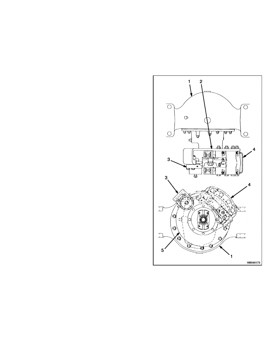
Description and Operation
The auxiliary brake system uses a disc brake in-
stalled at the rear of the differential housing. See
Figure 1 for typical configuration.
The auxiliary
brake is applied with the service brake for additional
braking force. This brake is a caliper brake with
one caliper that has two pistons in each half of the
caliper. Two pistons push from one side of the rotor
and two pistons push from the other side. The brake
rotor is installed on the pinion shaft.
Hydraulic pressure is created by operating the brake
treadle, which moves the oil through the shuttle
valve to the relay valve. The piston of the relay valve
then applies oil from the accumulator circuit to the
caliper pistons. The pistons then push the linings
against the disc.
1.
DIFFERENTIAL
2.
BRAKE ASSEMBLIES AND MOUNT
3.
PARKING BRAKE CALIPER
4.
AUXILIARY BRAKE CALIPER
5.
ROTOR
Figure 1. Auxiliary and Parking Brake
Assemblies
1
Auxiliary Brake Caliper Repair
1800 SRM 1040
Auxiliary Brake Caliper Repair
BRAKE LININGS
Remove
1.
Verify that the vehicle is on a level surface.
2.
Put blocks under the wheels to keep the vehicle
from moving.
3.
At one side of the caliper only, remove the bolts
that fasten the end plates. Remember to replace
the end plates if worn or damaged. See Figure 2.
4.
Slip out and discard the worn linings.
Clean and Inspect
CAUTION
Always replace both linings. If only one lining
is replaced, possible rotor damage can occur.
1.
Replace linings when the thickness of the lining
is less than 7.9 mm (0.31 in.) from the back plate.
2.
Replace the lining if the thickness of the two lin-
ings is different.
3.
Replace the linings if contaminated with oil or
grease.
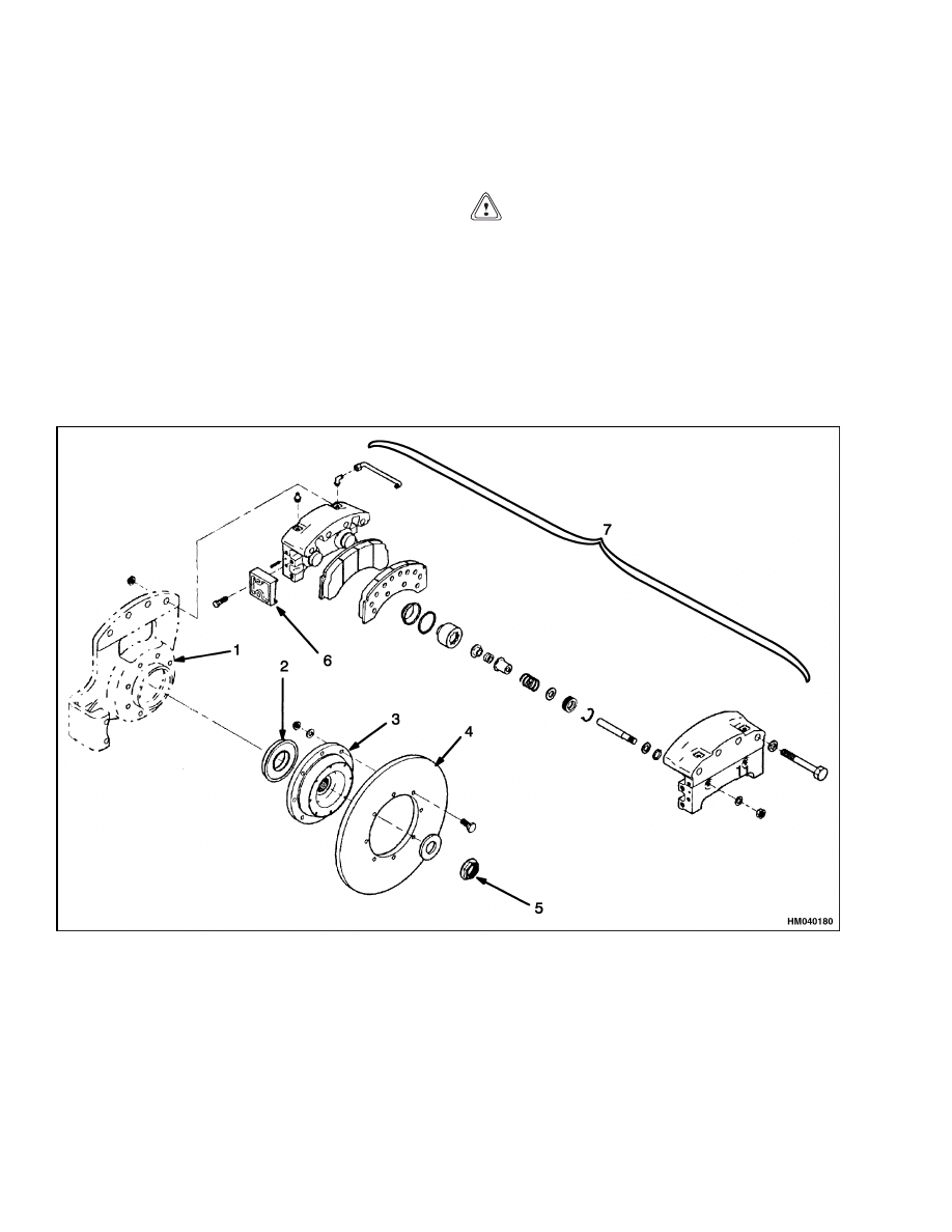
1.
CALIPER MOUNT
2.
OIL SEAL
3.
ROTOR FLANGE
4.
ROTOR
5.
NUT AND WASHER
6.
END PLATE
7.
CALIPER ASSEMBLY
Figure 2. Auxiliary Brake Assembly
2
1800 SRM 1040
Auxiliary Brake Caliper Repair
4.
Replace linings that have larger or deeper cracks
than the normal small, tight cracks on the sur-
face caused by the caliper when used under high
temperature conditions.
Install
CAUTION
When retracting the pistons, be careful not to
damage the dust boots.
1.
Use a piston retraction tool to force the pistons
back into the housings. Pry between the disc and
face of each piston until the pistons are fully re-
tracted. See Figure 3.
Figure 3. Piston Retraction Tool
2.
Slide new linings in position.
WARNING
Take care when using Loctite
®
to avoid seri-
ous personal injury.
Follow manufacturer’s
instructions to prevent irritation to eyes and
skin. If Loctite
®
gets into eyes, flush them with
water for 15 minutes. Have eyes checked by a
doctor as soon as possible.
3.
Apply Loctite
®
271 to the bolt threads and rein-
stall the end plates. Torque the bolts to 224 to
285 N•m (165 to 210 lbf ft).
4.
Verify the new linings slide freely between the
end plates.
AUXILIARY CALIPER
Remove
WARNING
To prevent serious eye injury, always wear safe
eye protection when doing maintenance or ser-
vice.
CAUTION
Always replace both linings. If only one lining
is replaced, possible disc damage can occur.
1.
Verify that the vehicle is on a level surface.
2.
Put blocks under the wheels to keep the vehicle
from moving.
3.
Remove brake linings. See Brake Linings.
4.
Remove the end plates that remain on the caliper
housing. See Figure 5.
WARNING
Before disconnecting any hydraulic lines, re-
lease pressure from the hydraulic circuit as fol-
lows:
a. Shut off the engine and completely lower
the carriage. Put blocks in front and behind
the wheels to prevent the lift truck from
moving.
b. Operate the lift/lower lever and the brake
pedals until the hydraulic pressure is re-
leased.
5.
Disconnect the hydraulic inlet line and remove
the crossover tube.
6.
Remove the two inner bolts that fasten the
caliper housing to the vehicle.
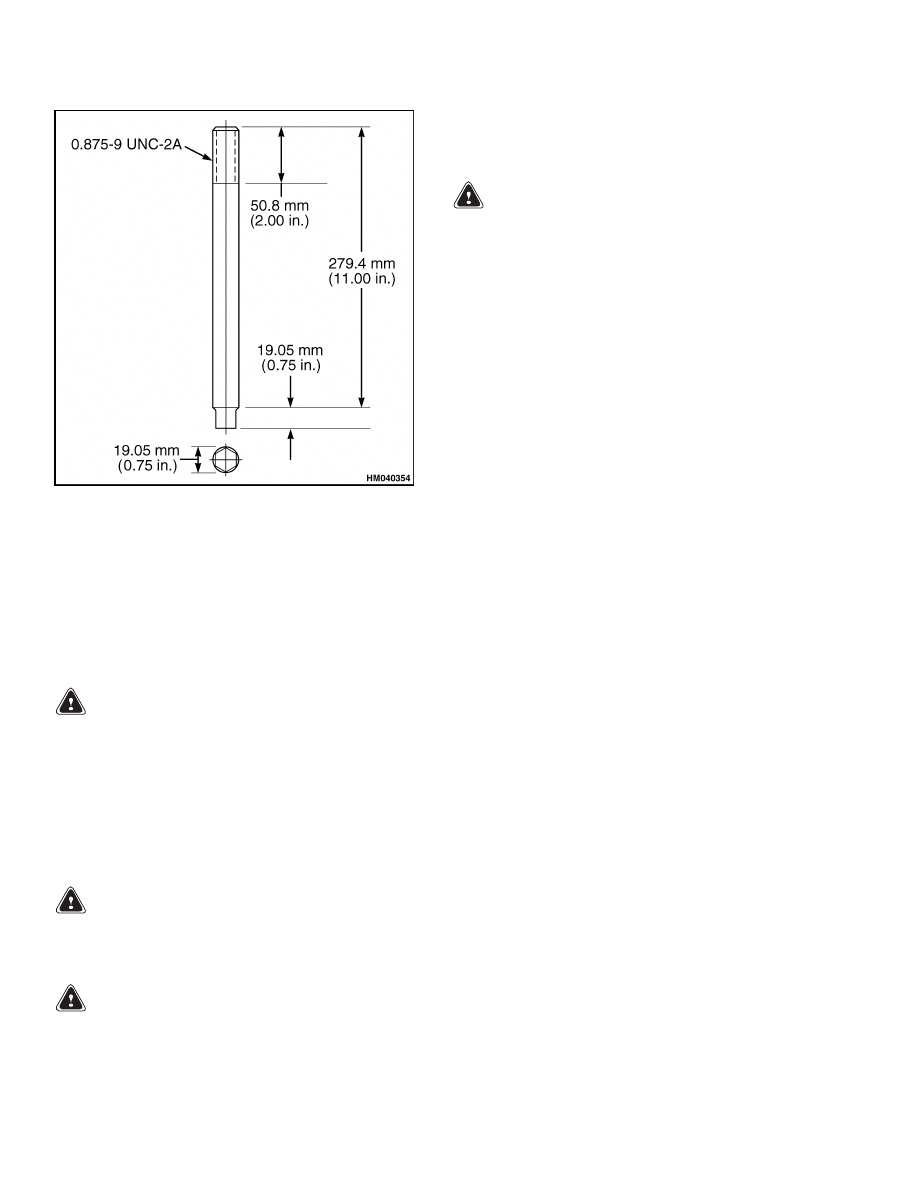
7.
Install two special studs to replace the two inner
bolts. See Figure 4.
3
Auxiliary Brake Caliper Repair
1800 SRM 1040
Figure 4. Brake Installation Stud
8.
Remove the two remaining bolts.
9.
Slide the outer caliper housing subassembly off
the special studs.
10. Unless the disc is to be removed, support the in-
ner caliper housing subassembly while removing
the two special studs.
WARNING
Verify lifting device has a minimum lifting rat-
ing of 100 kg (220.50 lb).
11. Use a lifting device to lift the caliper housing sub-
assembly clear of the disc.
Disassemble
Caliper
WARNING
To prevent serious eye injury, always wear safe
eye protection when doing maintenance or ser-
vice.
WARNING
Properly discard hydraulic fluid that is re-
moved from the brake system. Hydraulic fluid
that is removed can be contaminated and
cause damage, loss of braking, and serious
personal injury.
WARNING
Use only the type of hydraulic fluid specified
by Hyster. Do not use or mix different types
of hydraulic fluid. The wrong hydraulic fluid
can damage rubber parts of the caliper and can
cause damage, loss of braking, and serious per-
sonal injury.
1.
Drain hydraulic fluid from the housings. Cap or
plug the inlet openings.
2.
Remove the bolts and the end plates.
3.
Remove bleeder screws.
4.
Position the caliper housing so that the end of the
adjuster pin and nut are up. Use a screwdriver or
Allen wrench to hold the adjuster pin and remove
the nut and washer on each housing half.
5.
Carefully remove the dust boots from the pistons
and housing. See Figure 5.
6.
Use a 6.4 mm (0.25 in.) brass drift pin against
the adjuster pin to drive each piston subassembly
out of the housing.
7.
Remove the backup rings and O-rings.
Piston Subassembly
NOTE: Disassembly of the piston subassembly dur-
ing brake overhaul is not mandatory. Clean the pis-
ton subassembly thoroughly. If the piston surface
is acceptable for reuse and the piston subassembly
passes the functional tests for adjusting grip force,
spring force, and built in clearance (BIC), return the
piston subassembly into service.
1.
Remove the O-ring and adjuster pin washer. See
Figure 5.
2.
Remove the lock ring.
3.
Place the piston subassembly on an arbor press
table. See Figure 6.
4.
Use a special sleeve over the adjuster pin. See
Figure 7 and Figure 8.
4
1800 SRM 1040
Auxiliary Brake Caliper Repair
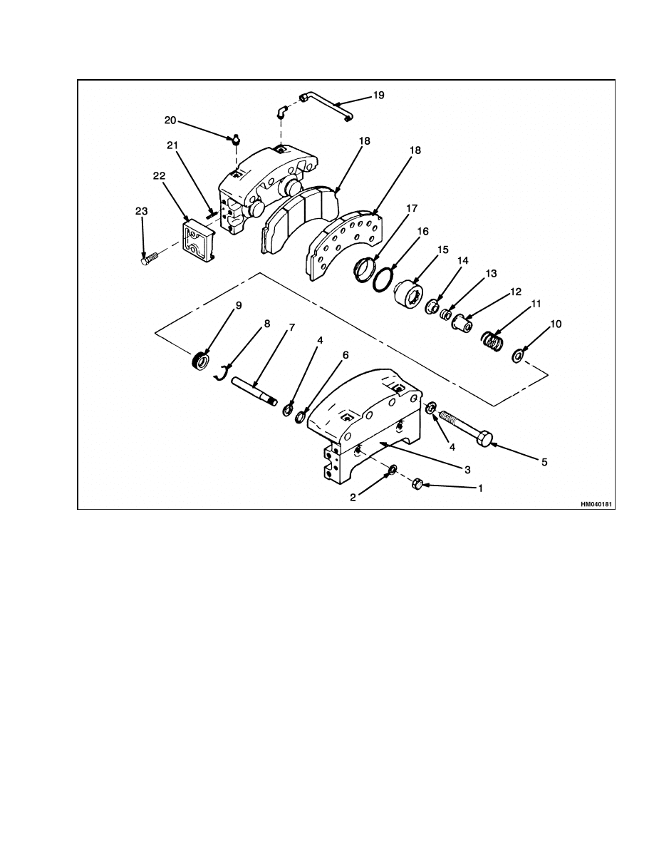
1.
NUT
2.
LOCKWASHER
3.
CALIPER HOUSING
4.
WASHER
5.
CALIPER BOLT
6.
GUIDE PIN O-RING
7.
GUIDE PIN
8.
LOCK RING
9.
THREADED RING
10. SPRING RETAINER
11. SPRING
12. OUTER SPRING GUIDE
13. GUIDE PIN ADJUSTER
14. INNER SPRING GUIDE
15. PISTON
16. PISTON O-RING
17. BOOT
18. LINING
19. TUBE
20. FITTING
21. ROLL PIN
22. END PLATE
23. END PLATE BOLT
Figure 5. Auxiliary Brake Components
5
Auxiliary Brake Caliper Repair
1800 SRM 1040
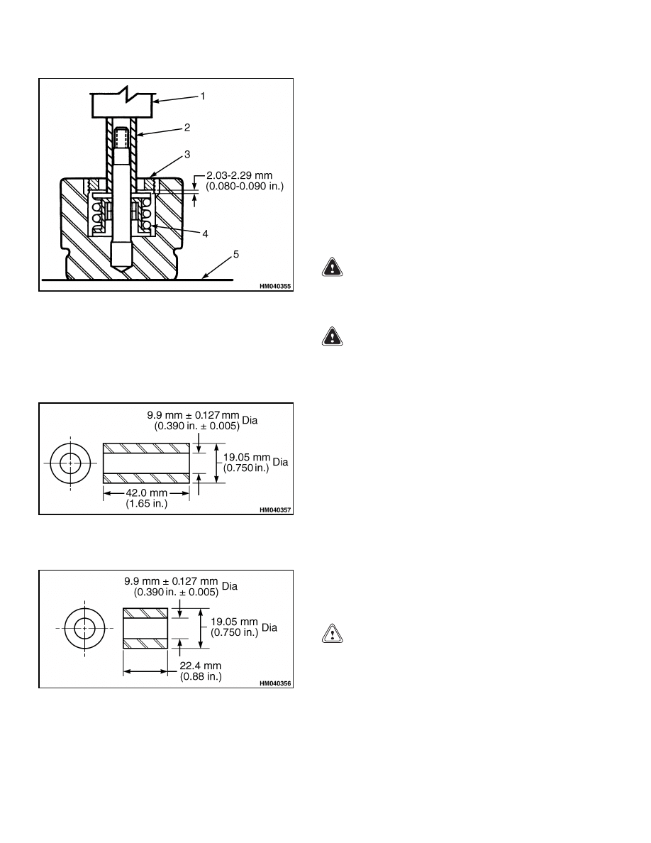
1.
ARBOR
2.
SPECIAL SLEEVE
3.
THREADED RING
4.
RETURN SPRING
5.
ARBOR PRESS TABLE
Figure 6. Arbor Press Setup for Piston
Subassembly
Figure 7. Long Grip Spacer and Installation
Sleeve
Figure 8. Short Grip Spacer and Installation
Sleeve
5.
Lower the arbor and compress the return spring
to minimum height and hold.
6.
Remove the threaded ring.
Use a spanner
wrench if the ring will not unscrew by hand.
7.
Slowly raise the arbor press until all compression
is relieved from the piston return spring.
8.
Remove the spring retainer, return spring, outer
spring guide, adjuster pin with grip assemblies,
inner spring guide, and piston.
Clean
WARNING
To prevent serious eye injury, always wear safe
eye protection when performing vehicle main-
tenance or service.
WARNING
To avoid personal injury when cleaning parts,
work in a well-ventilated area, wear protective
clothing (face shield or safety glasses and pro-
tective gloves), and follow chemical manufac-
turer’s recommendations for safe usage.
Solvent cleaners can be flammable, poisonous,
and cause burns. Examples of solvent clean-
ers are carbon tetrachloride, emulsion-type
cleaners, and petroleum-based cleaners.
To
avoid serious personal injury when using sol-
vent cleaners, carefully follow manufacturer’s
instructions and these procedures:
• Wear safe eye protection.
• Wear clothing that protects skin.
• Work in a well-ventilated area.
• Do not use gasoline or solvents that contain
gasoline. Gasoline can explode.
• Use hot solution tanks or alkaline solutions
correctly.
Carefully follow manufacturer’s
instructions.
CAUTION
Use only solvent cleaners to clean ground or
polished metal parts. Hot solution tanks or wa-
ter and alkaline solutions will damage these
parts. Isopropyl alcohol can be used for this
purpose.
1.
Use solvent cleaners to clean all metal parts that
have a ground or polished surface. Metal sur-
faces that have rough surface can be cleaned with
solvent cleaners or alkaline solutions.
6
1800 SRM 1040
Auxiliary Brake Caliper Repair
2.
Clean all threads and fittings with a wire brush.
3.
Clean all parts not made of metal with soap and
water.
4.
Scrape off all mud and dirt from the brake lin-
ings. Discard all linings contaminated with oil
or grease.
5.
Dry all parts with clean paper or rags.
6.
Apply hydraulic fluid used in the system to the
clean parts that are to be assembled. Do not ap-
ply fluid to the linings or disc.
Inspect
Caliper
1.
Inspect the piston, housing bore, and O-ring for
scratches or corrosion. Remove small scratches
or corrosion with fine emery cloth. Replace the
components if there are large scratches or exces-
sive corrosion.
2.
Measure the outer diameter of the piston. Re-
place the piston if the outer diameter is less than
66.57 mm (2.621 in.).
3.
Measure the diameter of the housing bore.
Replace the housing if the diameter exceeds
66.80 mm (2.630 in.).
4.
Inspect the housing for damage. If damage can-
not be repaired, replace the housing.
NOTE: Replace any component that has thread dam-
age that cannot be repaired.
5.
Inspect the caliper ports and end plate bolt holes
for thread damage. Use appropriate taps lubri-
cated with light oil to repair minor thread dam-
age. Use a 7/16-20 UNF-2B tap for the fluid ports
and a 5/8-11 UNC-2B tap for the end plate bolts.
Rotor
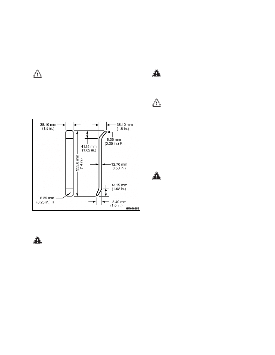
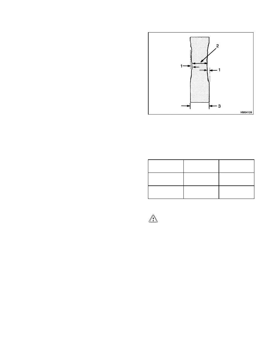
If the rotor is worn beyond the wear limits, replace
the disc. See Figure 9 and Table 1.
1.
MAXIMUM ROTOR THICKNESS
2.
MINIMUM ROTOR THICKNESS
3.
ORIGINAL ROTOR THICKNESS
Figure 9. Rotor Maximum Wear Limits
Table 1. Rotor Wear Limits
Original Rotor
Thickness
Maximum
Rotor Wear
Minimum
Rotor Wear
20 mm
(0.790 in.)
1.5 mm
(0.06 in.)
17 mm
(0.670 in.)
25.4 mm
(1.0 in.)
1.5 mm
(0.06 in.)
22.4 mm
(0.880 in.)
Piston Return Spring
CAUTION
If one defective spring is found, the other
return springs in the same brake assembly
should also be replaced.
Brake overheating
while in service usually causes this problem.
Check for hardening and compression set of
the piston seals and the backup rings. Check
for bluing of the steel back plates of the linings.
The free height of the return springs should be
30.16 mm (1.188 in.). Springs must be replaced
if below 28.58 mm (1.125 in.) free height.
1.
Check for a free height dimension of 30.16 mm
(1.188 in.).
A measured height of less than
28.58 mm (1.125 in.) is an indication that the
brake assembly has been subjected to high
temperature operation. This causes loss of the
spring force at working height.
7
Auxiliary Brake Caliper Repair
1800 SRM 1040
2.
Measure the spring force at maximum service de-
flection on a spring tester. See Figure 10.
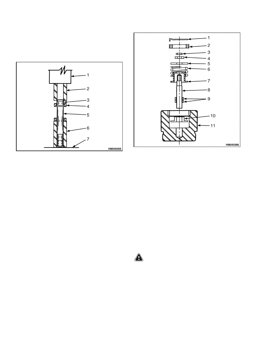
1.
TESTER ARBOR
2.
DIAL INDICATOR
3.
RETURN SPRING
4.
TESTER FORCE SCALE
5.
TESTER TABLE
6.
OUTER SPRING GUIDE
Figure 10. Inspecting Piston Return Springs
3.
Set up the dial indicator between the tester arbor
and the table. Place the outer spring guide under
the tester arbor and lower the arbor on the spring
guide. Hold the arbor in this position and reset
the indicator dial to zero.
4.
Raise the arbor and place the return spring over
the spring guide. Lower the arbor slowly until
the dial indicator reads zero. Read the spring
force on the tester scale. See Figure 10.
NOTE: This is the value of the spring return force
exerted under maximum deflection installed in the
piston subassembly. Because of manufacturing tol-
erances, this can be as low as 81.6 kg (180 lb), but
will usually measure greater than 90.7 kg (200 lb).
It is recommended that springs measuring less than
81.6 kg (180 lb) under these test conditions be re-
placed.
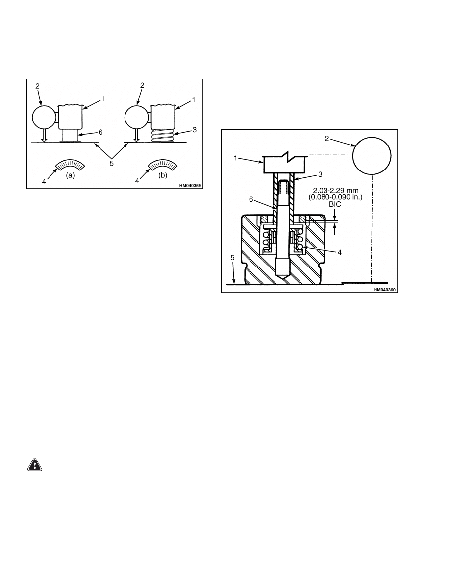
Piston Assembly Return Spring Force and Built-In
Clearance
WARNING
Follow all warnings and cautions regarding
press operation to avoid serious personal in-
jury and possible damage to components.
1.
Place the piston subassembly on a spring tester
table. Install the long special sleeve over the ex-
posed adjuster pin.
2.
Set the dial indicator between the spring tester
and arbor table. Use a dial indicator with a range
of 2.54 to 3.1 mm (0.100 to 0.122 in.) with incre-
ments of 0.0127 mm (0.0005 in.).
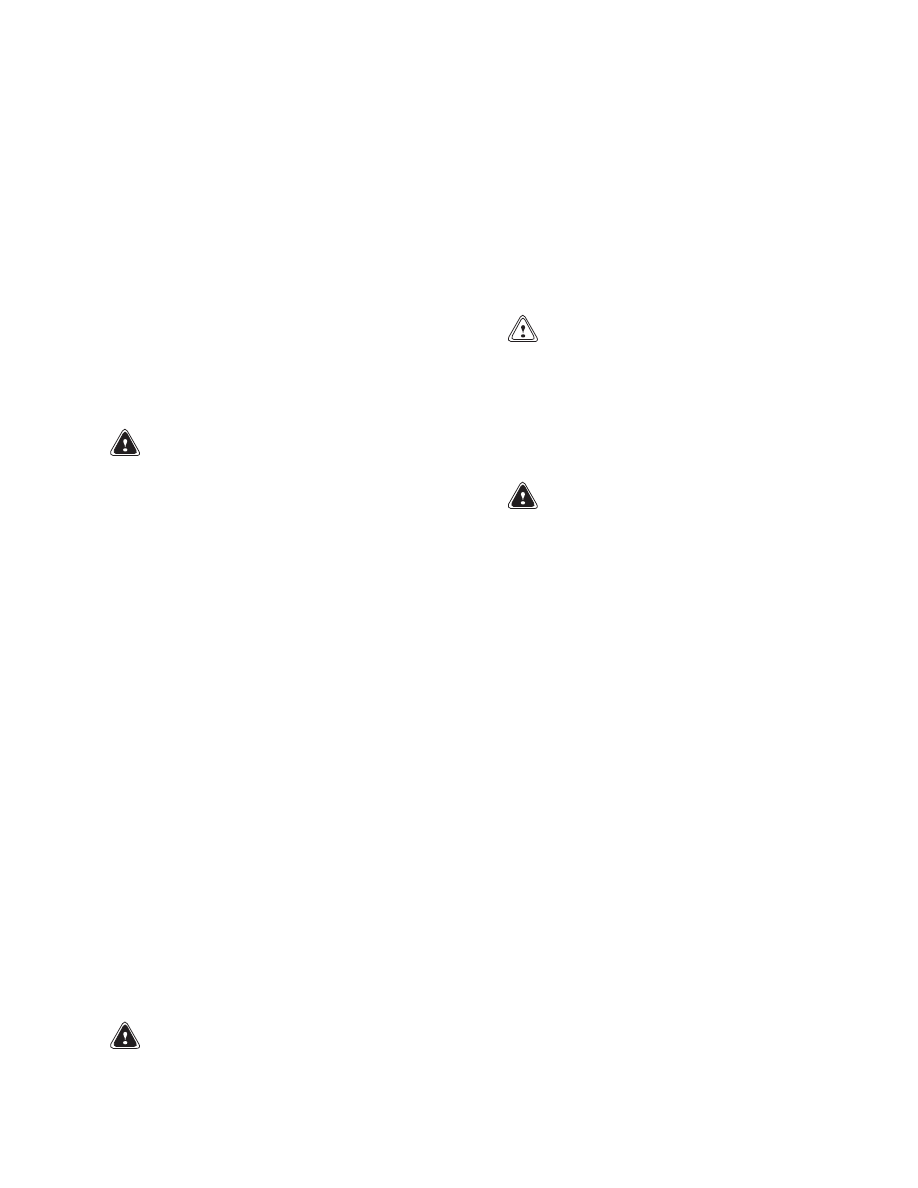
3.
Lower the spring arbor tester to compress the
spring to minimum height. This is when the in-
dicator point stops rotating. See Figure 11.
1.
ARBOR
2.
DIAL INDICATOR
3.
SPECIAL SLEEVE
4.
RETURN SPRING
5.
SPRING TESTER TABLE
6.
ADJUSTER PIN
Figure 11. Spring Tester Setup
4.
Rotate the indicator dial to zero while the spring
is compressed.
5.
Raise the arbor slowly until the spring tester
force scale reads zero. The indicator dial read-
ing will be the BIC (built-in clearance).
6.
Lower the arbor slowly until the indicator reads
zero again. The spring tester force scale will now
indicate the spring return force.
7.
Slowly raise and lower the arbor several times to
verify the BIC force and the spring return force.
NOTE: The return spring force should measure a
minimum of 81.6 kg (180 lb) when the spring is
compressed, the maximum amount in the piston
subassembly. Replace the spring if the reading is
less than 81.6 kg (180 lb).
8
1800 SRM 1040
Auxiliary Brake Caliper Repair
Piston Assembly Adjuster Grip Force
The adjuster grip force is the force required to cause
the adjuster pin to slip in the pair of adjuster grip
subassemblies.
CAUTION
Do not use a commercially available spring
tester for making adjuster grip force measure-
ments. Sudden adjuster grip force release can
damage the tester and cause need for repair
and recalibration.
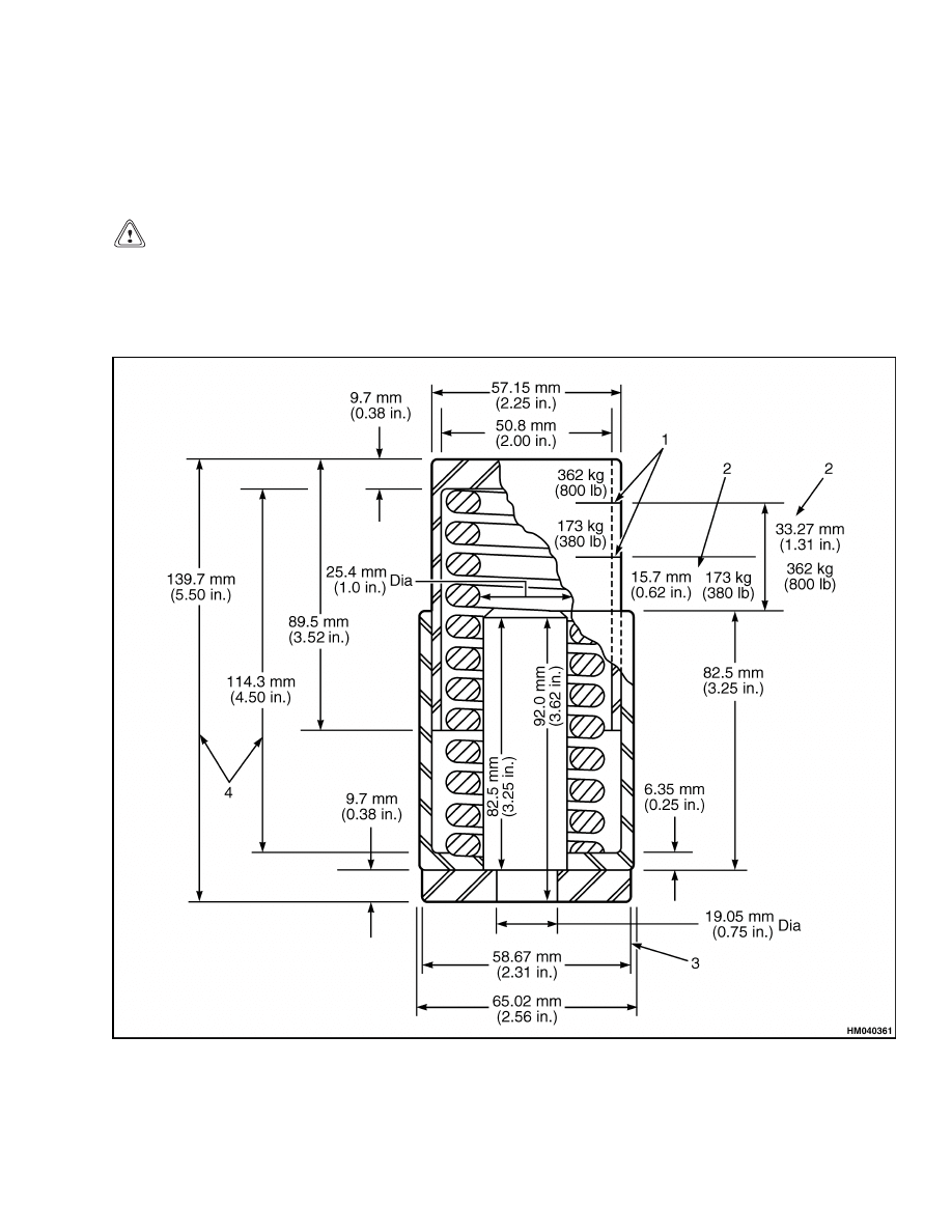
NOTE: A calibrated spring pod and an adjuster pin
extender tool are needed to perform the following
checks. See Figure 12 and Figure 13.
NOTE: If a hydraulic shop press with suitable re-
quirements is available, the calibrated spring pod is
not needed. The press must have a pressure gauge
with a 35.0 bar (500 psi) range accurately calibrated
to read bars (pounds) of force exerted by the ram.
1.
SCRIBE AND MARK
2.
DEFLECTION
3.
PRESS FIT
4.
FREE LENGTH
Figure 12. Calibrated Spring Pod
9
Auxiliary Brake Caliper Repair
1800 SRM 1040
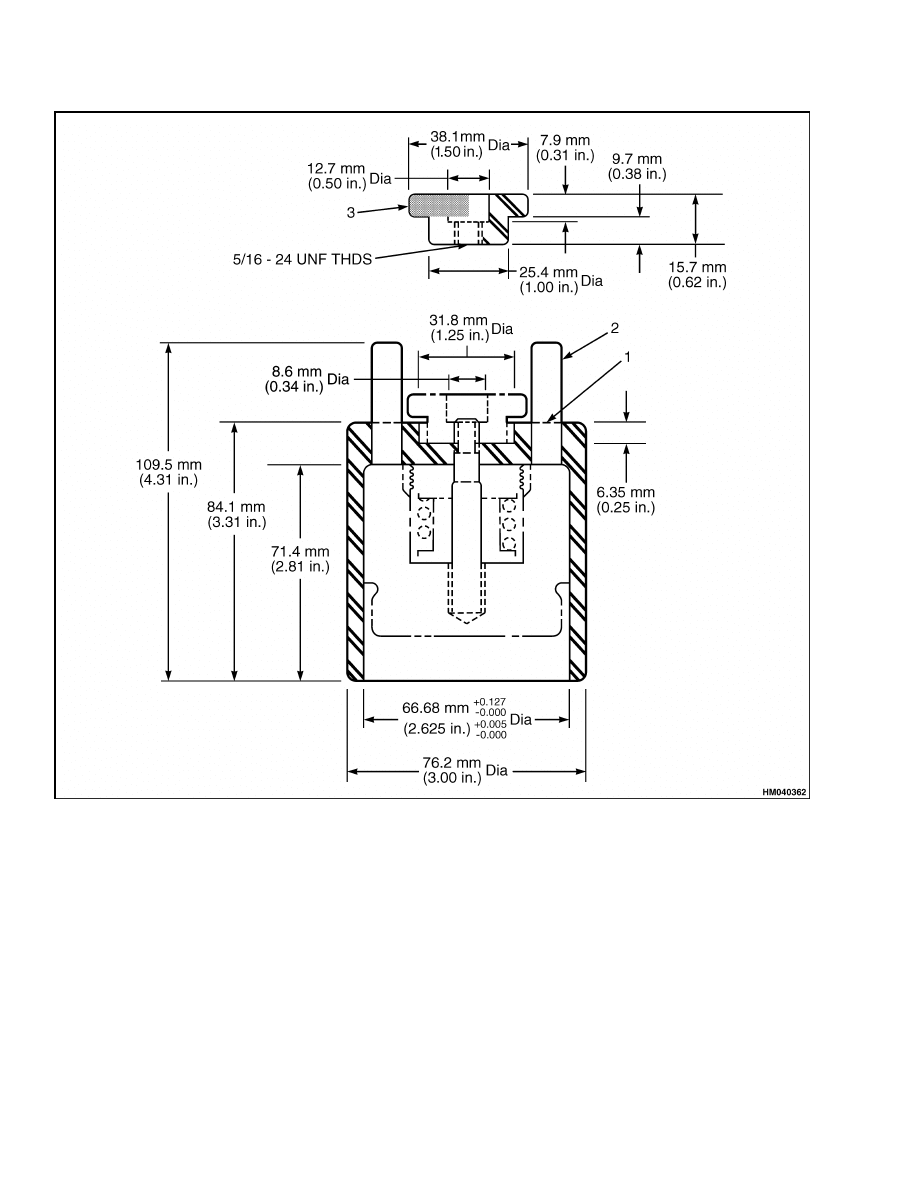
1.
3/8 DOWEL HOLES
2.
DOWEL PINS
3.
DIAMOND KNURL
Figure 13. Adjuster Pin Extender Tool
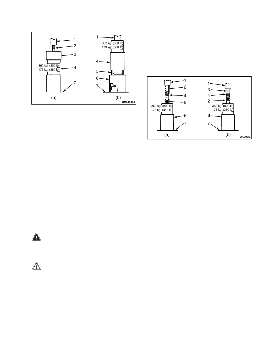
1.
Place the special calibrated spring pod on the ar-
bor press.
2.
Place the piston assembly on top of the spring
pod. Slowly lower the arbor to push in the ex-
tended adjuster pin. See Figure 14. The adjuster
pin should slide in the adjuster grip and move
downward between 173 to 362 kg (380 to 800 lb).
NOTE: The adjuster pin must be in the extended po-
sition for reassembly of the piston in the brake.
3.
Insert the piston assembly in the adjuster pin ex-
tender tool. Secure it firmly by using the knurled
nut on the adjuster pin.
10
1800 SRM 1040
Auxiliary Brake Caliper Repair
1.
ARBOR PRESS
2.
ADJUSTER PIN
3.
PISTON SUBASSEMBLY
4.
CALIBRATED SPRING POD
5.
DOWELS
6.
ADJUSTER PIN EXTENDER
7.
ARBOR PRESS TABLE
Figure 14. Checking Adjuster Grip Slip Force
4.
Place the piston assembly and the special tool un-
der the arbor and insert three 9.5 mm (0.374 in.)
dowel pins. Place the calibrated spring pod on
top of the dowels.
5.
Apply arbor force slowly to the top of the cali-
brated spring pod and verify that slippage occurs
between 173 to 362 kg (380 to 800 lb).
NOTE: If slippage occurs below 173 kg (380 lb) min-
imum or above 362 kg (800 lb) maximum force, the
adjuster pin and adjuster grips in the piston assem-
bly must be replaced.
Grip Force Adjuster Grip Assembly
WARNING
Follow all warnings and cautions regarding
press operation to avoid serious personal in-
jury and possible damage to components.
CAUTION
Do not use a spring tester for making adjuster
grip force measurements.
Sudden adjuster
grip force release can damage the tester and
cause need for repair and recalibration.
NOTE: To perform the following procedures you must
have either a calibrated spring pod or a force cali-
brated shop press.
1.
Place the spring pod on the arbor press table.
Use short and long sleeve spacers to slip adjuster
grips back and forth on the adjuster pin. See
Figure 15.
1.
ARBOR
2.
SPECIAL SLEEVE, LONG
3.
ADJUSTER PIN
4.
GRIP ASSEMBLIES
5.
SPECIAL SLEEVE, SHORT
6.
CALIBRATED SPRING POD
7.
ARBOR PRESS TABLE
Figure 15. Checking Grip Force
2.
Apply force from the arbor slowly to verify that
slippage occurs between the 173 to 362 kg (380
to 800 lb) markings on the spring pod.
3.
If slippage occurs in the required force limits, slip
grips back into position as shown in view (b) in
Figure 15.
4.
If slippage occurs below 173 kg (380 lb), either
the grips or the grips and adjuster pin must be
replaced.
Use the long sleeve spacer and the
arbor press to slip the grips off the adjuster
pin. Inspect the adjuster pin for nicks and wear.
Slight nicks that can be polished out by hand
can be reused if subsequent slip inspection is
in required measurements.
Replace adjuster
pins that are bent or worn to less than 9.5 mm
(0.374 in.) diameter.
11
Auxiliary Brake Caliper Repair
1800 SRM 1040
5.
If replacement is required, use the following pro-
cedures:
a. Install the adjuster grips on the adjuster pin.
See Figure 16.
1.
ARBOR
2.
SPECIAL SLEEVE, SHORT
3.
PILOT PIN
4.
ADJUSTER GRIP ASSEMBLY
5.
ADJUSTER PIN
6.
SPECIAL SLEEVE, LONG
7.
ARBOR PRESS TABLE
Figure 16. Installing Adjuster Grips on the
Return Pin
b. Place the adjuster grip and pilot pin assem-
bly on the adjuster pin.
c.
Press the adjuster grip off the expendable pi-
lot pin onto the adjuster pin.
d. Press the second grip onto the adjuster pin.
Continue to press the adjuster pin until it
contacts the previously installed grip.
e.
Recheck the grip force of the adjuster grip
assembly.
Assemble
Piston Subassembly
1.
Install the inner spring guide in the piston cavity.
See Figure 17.
1.
LOCK RING
2.
THREADED RING
3.
O-RING
4.
ADJUSTER PIN WASHER
5.
SPRING RETAINER
6.
RETURN SPRING
7.
OUTER SPRING GUIDE
8.
ADJUSTER PIN
9.
ADJUSTER GRIP
10. INNER SPRING GUIDE
11. PISTON
Figure 17. Piston Subassembly
2.
Install the adjuster pin with grip assemblies.
3.
Install the outer spring guide.
4.
Install the return spring.
5.
Install the spring retainer.
WARNING
Follow all warnings and cautions regarding
press operation to avoid serious personal in-
jury and possible damage to components.
6.
Place the piston assembly on the arbor press ta-
ble.
7.
Place the long special sleeve over the adjuster
pin.
Place the threaded ring over the special
sleeve.
12
1800 SRM 1040
Auxiliary Brake Caliper Repair
8.
Slowly lower the arbor to compress the return
spring to minimum height and hold.
9.
Use an adjustable wrench to screw the threaded
ring against the spring retainer.
Verify the
threaded ring is bottomed.
NOTE: The following step provides the required
built-in clearance (BIC).
10. Keeping the spring compressed,
back the
threaded ring off one full turn, plus additional
amount to install the lock ring in the second
available lock ring position.
11. Raise the arbor and install lock ring.
Caliper
WARNING
Use only specified components when assem-
bling the caliper. Do not use components from
other calipers. If the wrong components are
installed, the caliper will not operate correctly
and can cause damage to the equipment. Use
of parts not approved by Hyster can cause
damage and loss of braking which could result
in serious personal injury.
1.
Position the housings on a work surface with the
cylinder bores up.
2.
Lubricate all cylinder bores, threads, seals,
backup rings, piston seal surfaces, and seal
grooves with Dow
®
Corning DC4 or with the
type of hydraulic fluid used in the system.
3.
Install a new O-ring into the groove of each hous-
ing cylinder bore. Push the O-rings to the bottom
of the grooves.
4.
Install a new piston backup ring above each pis-
ton O-ring so that the curved side of the piston
backup ring is against each piston O-ring.
5.
Install a washer and a new O-ring on the exposed
part of each adjuster pin.
6.
Gently push and twist each piston subassembly
past the O-ring and backup ring until the O-ring
and washer are seated in the bottoms of the cav-
ities.
WARNING
When installing dust boots, avoid pushing
boots against the sharp edge of the boot
groove.
This can cut the underside of the
boots and cause failure of boots in service.
This can cause loss of braking and serious
personal injury.
7.
Carefully install new dust boots keeping them
free of lubricant.
8.
Position the housing subassemblies with ad-
juster pins up and install the lockwashers and
nuts.
CAUTION
Avoid turning the adjuster pin when tightening
the nuts. This can cause damage to the O-ring
and cause the seal to leak.
9.
Hold the adjuster pin using a screwdriver
or Allen wrench and torque nuts to 13.6 to
17.0 N•m (120 to 150 lbf in).
WARNING
Follow all warnings and cautions regarding
press operation to avoid serious personal in-
jury and possible damage to components.
10. Place each housing subassembly on the arbor
press and press the piston subassemblies into
their cavities to the maximum retracted position.
11. Install fittings and bleeder screws in the hous-
ing subassemblies according to 12 o’clock and 6
o’clock installation requirements.
Install
1.
Slide the caliper housing subassembly between
the disc and axle mounting. Support the hous-
ing subassembly in place while installing the two
special studs in the two inner bolt holes.
2.
Slide the remaining housing assembly over the
two special studs and install the two inner bolts.
3.
Remove special studs and install remaining
bolts.
4.
Torque the inner and outer bolts to 746 to
881 N•m (550 to 650 lbf ft).
5.
Install the crossover tube and reconnect the hy-
draulic fluid inlet line.
6.
Install new linings. See Brake Linings.
13

Auxiliary Brake Caliper Repair
1800 SRM 1040
WARNING
Take care when using Loctite
®
to avoid seri-
ous personal injury.
Follow manufacturer’s
instructions to prevent irritation to eyes and
skin. If Loctite
®
gets into eyes, flush them with
water for 15 minutes. Have eyes checked by a
doctor as soon as possible.
7.
Apply Loctite
®
271 to the bolt threads and rein-
stall the remaining end plates. Torque the bolts
to 224 to 285 N•m (165 to 210 lbf ft).
8.
Verify the new linings slide freely between the
end plates.
9.
Remove all air from the brake hydraulic system.
See Bleed Brakes.
10. Adjust the brakes. See Adjust.
Bleed Brakes
WARNING
Remove air from the brake system after each
installation or repair of hydraulic or brake sys-
tem components or hydraulic lines. The brakes
will not operate correctly with air in the system
and can cause injury or damage.
NOTE: This brake is designed to bleed correctly at
the 12 o’clock and 6 o’clock positions.
• When mounted at the 12 o’clock position, place the
two bleeders at the two upper ports. Connect the
inlet line to one of the four lower ports and use the
three remaining bleeders at the other three ports.
• When the brake is mounted at the 6 o’clock posi-
tion, install four bleeders at the uppermost ports.
Then connect the inlet line to one of the two re-
maining ports, and install the last bleeder at the
remaining lower port.
Always start at the point that is the farthest from
the master cylinder and work back toward the mas-
ter cylinder.
Bleed every bleeder screw on every
caliper at every brake position. When you complete
a caliper, go to the next closest caliper on the same
wheel. When you complete a wheel, go to the fur-
thest bleeder screw on the next closest wheel.
WARNING
Properly discard hydraulic fluid that is re-
moved from the brake system. Hydraulic fluid
that is removed can be contaminated and
cause damage, loss of braking, and serious
personal injury.
WARNING
Use only the type of hydraulic fluid specified
by Hyster. Do not use or mix different types
of hydraulic fluid. The wrong hydraulic fluid
can damage rubber parts of the caliper and can
cause damage, loss of braking, and serious per-
sonal injury.
1.
Verify that the master cylinder is filled. Keep the
master cylinder filled during bleeding so you do
not draw air into the system through the master
cylinder. Verify that the master cylinder is filled
when you are done bleeding the system.
2.
Put a clear tube on the bleeder screw. Place the
other end of the clear tube in a container of clean
hydraulic fluid.
3.
Bleed brakes.
a. For full hydraulic systems:
(1)
Slowly apply hydraulic pressure to the
caliper.
(2)
Loosen the bleeder screw and continue
to apply pressure until no air bubbles
appear in the container of fluid.
(3)
Tighten the bleeder screw to 11.3 to
13.6 N•m (100 to 120 lbf in). Release
the pressure to the caliper.
b. For air/hydraulic or mechanical actuator sys-
tems:
(1)
Apply brake pedal, then loosen the
bleeder screw.
(2)
Tighten the bleeder screw to 11.3 to
13.6 N•m (100 to 120 lbf in) before re-
leasing the brake so air is not pulled
back into the system.
(3)
Repeat Step (1) and Step (2) until no air
bubbles appear in the container of fluid
when you apply the brake pedal.
4.
Apply and release the brakes three times to ver-
ify that the caliper operates correctly.
5.
Check for fluid leaks.
6.
Verify that the linings move freely in the caliper.
14

1800 SRM 1040
Troubleshooting
Adjust
1.
Put blocks under the wheels to keep the vehicle
from moving.
2.
Start the engine and operate the brake pedal.
This will apply hydraulic pressure to the auxil-
iary brake pedal.
3.
Verify that the caliper moves freely on the align-
ment pins.
4.
Slide the caliper so that one of the linings is
against the disc.
5.
Measure the clearance between the lining and
the disc. If the clearance is greater than 3.4 mm
(0.13 in.), continue with adjustment procedures.
6.
Tighten the nut until it touches the spring cover.
Apply the parking brake to release hydraulic
pressure.
Troubleshooting
PROBLEM
POSSIBLE CAUSE
PROCEDURE OR ACTION
The brake does not apply.
Fluid reservoir is low or empty.
Fill reservoir to correct level.
Damage to the hydraulic system.
Repair hydraulic system.
No pressure to the brake.
Fill reservoir to correct level.
Brake leaking from the bleeder
screw.
Tighten the bleeder screw to 11.3 to
13.6 N•m (100 to 120 lbf in).
Brake leaking at an inlet fitting.
Replace and/or tighten the inlet fit-
ting.
Brakes leaking from O-rings and/or
backup rings.
Replace O-rings and/or backup rings.
Inspect piston for wear and damage.
Brakes leaking because of a loose ad-
juster pin nut.
Tighten the adjuster pin nut to 13.6
to 17 N•m (120 to 150 lbf in).
Linings are worn or damaged.
Replace linings.
Linings have uneven wear.
Inspect piston, caliper bore, housing,
and end plates. Replace and service
as necessary.
Linings are contaminated with oil or
grease.
Replace linings.
The brake does not release.
Parking brake is applied.
Release the parking brake.
Damage to the hydraulic system.
Repair hydraulic system.
A brake line has a restriction.
Replace line.
The brake pedal valve(s) is damaged.
Replace brake pedal valve.
The brake linings are damaged.
Replace brake linings.
15

Troubleshooting
1800 SRM 1040
PROBLEM
POSSIBLE CAUSE
PROCEDURE OR ACTION
The brake does not release.
(Cont.)
The auxiliary brake rotor is dam-
aged.
Replace auxiliary rotor.
Vehicle or equipment not operated
correctly.
Advise operator on correct vehicle or
equipment operation.
Piston is cocked in the bore.
Check
the
piston
diameter
and
replace
if
less
than
66.57
mm
(2.621 in.). Inspect the caliper bore
and replace the housing if the bore
diameter is greater than 66.80 mm
(2.630 in.). Inspect linings and re-
place if they have tapered wear.
Adjuster assembly is not adjusted
correctly.
Check and adjust.
16


TECHNICAL PUBLICATIONS
1800 SRM 1040
3/05 (4/03)(3/03) Printed in United Kingdom
Document Outline
- toc
- tables
Wyszukiwarka
Podobne podstrony:
1531821 1800SRM1037 (03 2005) UK EN
897653 1800SRM0566 (04 2005) UK EN
897953 1600SRM0639 (03 2005) UK EN
1598459 1900SRM1213 (03 2005) UK EN
897956 1900SRM0642 (03 2005) UK EN
1510466 1800SRM0985 (05 2005) UK EN
897963 4500SRM0649 (03 2005) UK EN
1565789 1800SRM1117 (08 2005) UK EN
1573930 0600SRM1172 (03 2005) UK EN
1554629 1800SRM1076 (03 2004) UK EN
1586985 2200SRM1178 (03 2005) UK EN
1529749 1800SRM1036 (08 2005) UK EN
897345 1400SRM0413 (03 2005) UK EN
899782 2000SRM0077 (03 2005) UK EN
1466229 1800SRM0734 (05 2005) UK EN
897875 8000SRM0616 (03 2005) UK EN
1482623 1800SRM0803 (03 2000) UK EN
więcej podobnych podstron