INSTRUMENT PANEL,
INDICATORS, AND
SENDERS
RS45-27CH, RS45-30CH, RS45-27IH, RS46-33CH,
RS46-30IH, RS46-36CH, RS46-33IH First Used
on 1563, 1566, 1567, 1568, 1570, and Up [A222]
PART NO. 1586985
2200 SRM 1178

SAFETY PRECAUTIONS
MAINTENANCE AND REPAIR
• When lifting parts or assemblies, make sure all slings, chains, or cables are correctly
fastened, and that the load being lifted is balanced. Make sure the crane, cables, and
chains have the capacity to support the weight of the load.
• Do not lift heavy parts by hand, use a lifting mechanism.
• Wear safety glasses.
• DISCONNECT THE BATTERY CONNECTOR before doing any maintenance or repair
on electric lift trucks. Disconnect the battery ground cable on internal combustion lift
trucks.
• Always use correct blocks to prevent the unit from rolling or falling. See HOW TO PUT
THE LIFT TRUCK ON BLOCKS in the Operating Manual or the Periodic Mainte-
nance section.
• Keep the unit clean and the working area clean and orderly.
• Use the correct tools for the job.
• Keep the tools clean and in good condition.
• Always use HYSTER APPROVED parts when making repairs. Replacement parts
must meet or exceed the specifications of the original equipment manufacturer.
• Make sure all nuts, bolts, snap rings, and other fastening devices are removed before
using force to remove parts.
• Always fasten a DO NOT OPERATE tag to the controls of the unit when making repairs,
or if the unit needs repairs.
• Be sure to follow the WARNING and CAUTION notes in the instructions.
• Gasoline, Liquid Petroleum Gas (LPG), Compressed Natural Gas (CNG), and Diesel fuel
are flammable. Be sure to follow the necessary safety precautions when handling these
fuels and when working on these fuel systems.
• Batteries generate flammable gas when they are being charged. Keep fire and sparks
away from the area. Make sure the area is well ventilated.
NOTE: The following symbols and words indicate safety information in this
manual:
WARNING
Indicates a condition that can cause immediate death or injury!
CAUTION
Indicates a condition that can cause property damage!

Instrument Panel, Indicators, and Senders
Table of Contents
TABLE OF CONTENTS
General ...............................................................................................................................................................
Description .........................................................................................................................................................
General ...........................................................................................................................................................
Instrument Panel Meters, Indicators, and Switches...............................................................................
Container Handler Controls .....................................................................................................................
Intermodal Handler Controls ...................................................................................................................
3B6 Load Limiter System .........................................................................................................................
Senders ......................................................................................................................................................
Instrument Panel Component Replacement ....................................................................................................
General ...........................................................................................................................................................
Instrument Panel...........................................................................................................................................
Remove.......................................................................................................................................................
Install .........................................................................................................................................................
Container/Intermodal Handler Controls ......................................................................................................
Remove.......................................................................................................................................................
Install .........................................................................................................................................................
3B6 Load Limiter System .........................................................................................................................
Replace...................................................................................................................................................
Sender Replacement ..........................................................................................................................................
Fuel Level Sender ..........................................................................................................................................
Pressure Sender.............................................................................................................................................
Temperature Sender ......................................................................................................................................
Low Coolant Sender.......................................................................................................................................
Crankshaft Position Sensor ..........................................................................................................................
This section is for the following models:
RS45-27CH, RS45-30CH, RS45-27IH, RS46-33CH, RS46-30IH, RS46-36CH,
RS46-33IH First Used on 1563, 1566, 1567, 1568, 1570, and Up [A222]
©2005 HYSTER COMPANY
i

"THE
QUALITY
KEEPERS"
HYSTER
APPROVED
PARTS
2200 SRM 1178
Description
General
Meters provide information to the operator on the
condition of various systems. Gauges may be either
direct reading (mechanical) or indirect (electrical).
Unlike mechanical gauges, electrical gauges have
electrical meter movements, light emitting diodes
(LEDs), or digital displays inside the case. These me-
ters receive an electrical signal from a sender unit,
usually in the engine or transmission case.
This
section only describes electrical meters, senders, and
instrument panel displays.
Meters and displays are used to provide operator in-
formation on the status of many systems including
engine oil pressure, fuel level, transmission oil pres-
sure, engine coolant temperature, transmission oil
temperature, hour display, and transmission fault
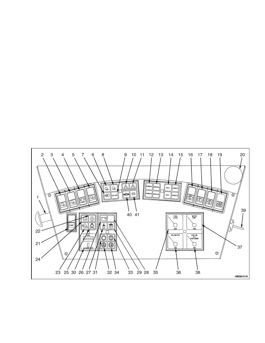
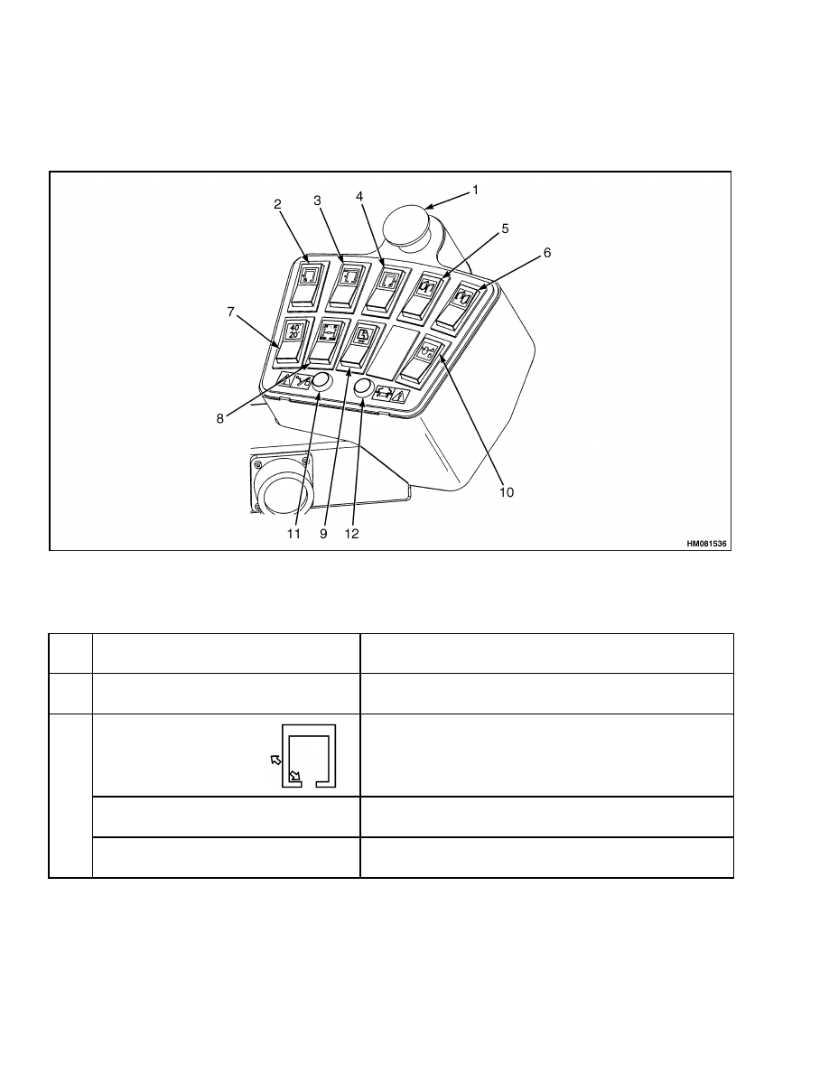
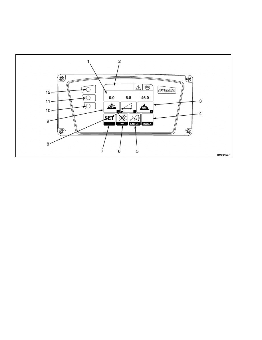
codes. See Figure 1 and Table 1.
Description
GENERAL
Many meters have meter movements that move an
indicating needle attached to a shaft (or pin). The
shaft rotates to swing the needle. Shaft rotation of
a meter is limited to less than one full revolution.
Meter faces are calibrated to indicate a range of val-
ues. For examples of meter faces and indicators, see
Figure 1 and Table 1.
Many meters and displays require a separate sender.
Figure 1. Instrument Panel and Indicators
1
Description
2200 SRM 1178
Instrument Panel Meters, Indicators, and Switches
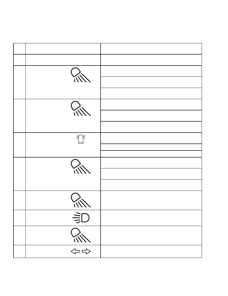
Table 1. Instrument Panel and Indicators
Item
No.
Item
Function
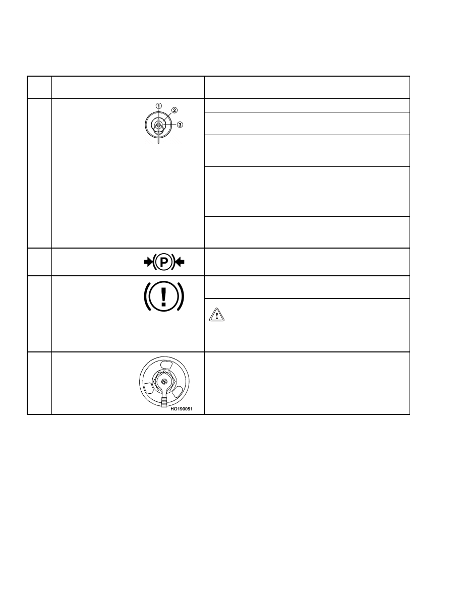
1
Emergency
Engine Stop
Push this red knob to STOP the engine.
This switch controls the operation of the chassis lights
as follows:
• Push the switch to the first position to turn the marker
lights ON.
2
Chassis Light
Switch
• Push the switch to the second position to turn the front
work lights ON.
This switch controls the operation of the boom lights as
follows:
• Push the switch to the first position to turn the 20’
lights ON.
3
Boom Light
Switch
• Push the switch to the second position to turn the 40’
lights ON.
This switch controls the operation of the rotating
beacons as follows:
• Push the switch to turn the beacons ON.
4
Beacon Light
Switch
• Push the top of the switch to turn the beacons OFF.
This switch controls the operation of the spreader lights
as follows:
• Push this switch to the first position to turn the rear
work lights ON.
5
Work Light Switch
• Push the switch to the second position to turn spreader
work lights ON.
6
Indicator for
Chassis Lights
The amber light is ON when the chassis lights are ON.
7
Indicator for High
Beams
The amber light is ON when the high beams are ON.
8
Indicator for Boom
Lights
The amber light is ON when the boom lights are ON.
9
Turn Signal
Indicator
The green arrows indicate the turn signal is operating.
2
2200 SRM 1178
Description
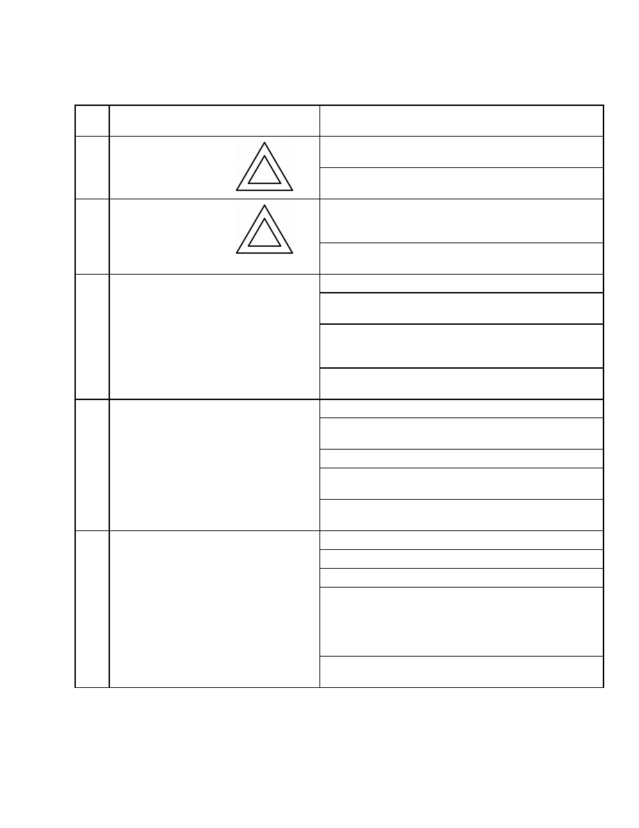
Table 1. Instrument Panel and Indicators (Continued)
Item
No.
Item
Function
The red light is ON when the operator has pushed the
button to override the load limiter system.
10
Load Limiter
Override Warning
Light
NOTE: Both upper and lower lights have the same func-
tion.
The red light is ON and an audible alarm is activated
when the operator has pushed the rotator override
button.
11
Rotator Override
Warning Light
NOTE: Both upper and lower lights have the same func-
tion.
The amber lights function as follows:
• ON: Laydown at both left side corners of the container
is correct.
• OFF: All other conditions.
Left-hand legs properly
closed (legs standard with Intermodal Handling at-
tachment).
12
Amber Left-Side
Position Indicator
Lights
NOTE: Both upper and lower lights have the same func-
tion.
The green indicator lights function as follows:
• ON: Twist locks closed. Shoes properly engaged (shoes
standard with Intermodal Handling attachment).
• OFF: In all other conditions.
NOTE: The combination of amber and green lights indi-
cates the correct condition to lift the load.
13
Green Indicator
Lights
NOTE: Both upper and lower lights have the same func-
tion.
The red lights function as follows:
• ON: Twist locks unlocked.
• OFF: In all other conditions.
NOTE: The red light should be ON before lifting the
spreader off the load. (Optional with Intermodal Han-
dling attachment): The red light is ON while the front
legs move from VERTICAL, HORIZONTAL, or RE-
VERSE.
14
Red Indicator
Lights
NOTE: Both upper and lower lights have the same func-
tion.
3
Description
2200 SRM 1178
Table 1. Instrument Panel and Indicators (Continued)
Item
No.
Item
Function
The amber lights function as follows:
• ON: Laydown at both right-hand corners of the con-
tainer is correct.
• OFF: In all other conditions.
(Optional with Inter-
modal Handling attachment): Right side legs properly
closed.
15
Amber Right-Side
Position Indicator
Lights
NOTE: Both upper and lower lights have the same func-
tion.
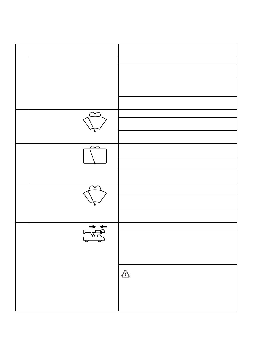
The switch controls the top wiper and washer as follows:
• Push the top of the switch to the first position to turn
ON the windshield wiper.
16
Top Wiper Switch
• Push the top of the switch past the ON position to ac-
tivate the window washer.
The switch controls the operation of rear wiper as
follows:
• Push the top of the switch to the first position to turn
ON the rear wiper.
17
Rear Wiper
Switch
• Push the top of the switch past the ON position to ac-
tivate the window washer.
The switch controls the front windshield wiper and
windshield washer as follows:
• Push the top of the switch to the first position to turn
ON the windshield wiper.
18
Front Windshield
Wiper Switch
• Push the top of the switch past the ON position to ac-
tivate the windshield washer.
Push switch to override the 3B6 load limiter system.
NOTE: The override switch disables the 3B6 load limiter
system. When the 3B6 load limiter system is disabled,
the boom can be lowered or extended under conditions not
permitted by the 3B6 load limiter system. Extending or
lowering the boom may be necessary to free the container
from the ReachStacker
®
.
19
3B6 Load Limiter
Override Switch
CAUTION
Extending or lowering the boom or handling loads
which are too heavy can overload the Reach-
Stacker.
Overloading can damage the truck or
cause tipping. Disable the 3B6 load limiter system
only if required to free the truck from a container.
Do NOT overload the ReachStacker.
4
2200 SRM 1178
Description
Table 1. Instrument Panel and Indicators (Continued)
Item
No.
Item
Function
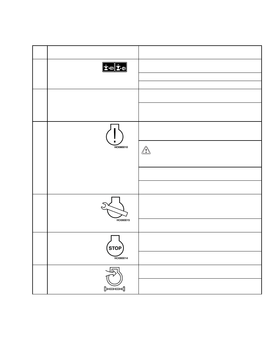
This switch controls the operation of the parking brake
as follows:
• Push knob to release the parking brake.
20
Parking Brake
Switch
• Pull knob to apply the parking brake.
Push and hold switch, then turn the key switch to start
the engine.
21
Start Engine and
Warning Light
Test Switch
Release the switch when the engine starts and is
running properly. Pushing on this switch also tests the
operation of the warning lights.
The warning light will come ON when the engine
operating conditions are near the maximum permissible
values. Engine power derating may take place.
CAUTION
Operating conditions might deteriorate. Monitor
engine operating conditions.
NOTE: The warning and stop lights are also used when
the diagnostic mode is selected.
22
Limited
Operating
Conditions
Warning Light
NOTE: See the section diagnostics in the maintenance
section of this manual.
The maintenance light will come ON when one or more
fluid levels are low. Upon the power up of the ECM
(Engine Control Module), the maintenance light will
flash when oil change is due.
23
Maintenance
Light
NOTE: See the section diagnostics in the maintenance
section of this manual.
The stop light will come ON when engine conditions are
beyond the maximum permissible values. The engine
will immediately shut off to prevent damage.
24
Stop Light
NOTE: See the section diagnostics in the maintenance
section of this manual.
The amber light is ON when the start switch (21) is
pushed and must go OFF when the engine is running.
25
Air Filter
Restriction
Warning Light
If light is ON while engine is running, the air filter is
dirty and replacement is required.
5
Description
2200 SRM 1178
Table 1. Instrument Panel and Indicators (Continued)
Item
No.
Item
Function
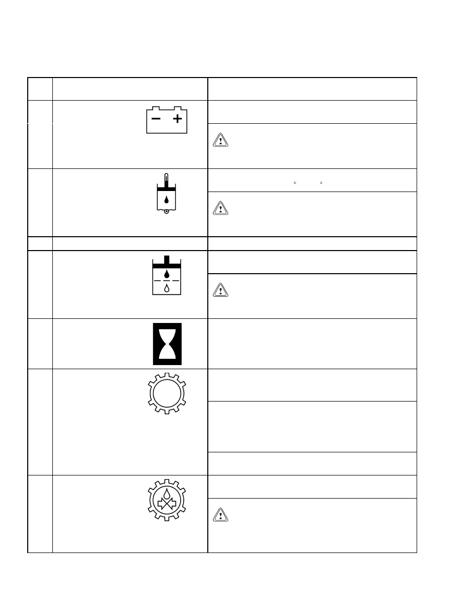
The red light will come ON when the alternator is not
charging the battery.
26
Battery Discharge
Warning Light
CAUTION
Do not continue to operate the vehicle when the
red light is ON at engine speeds above idle.
The red light is ON when the temperature of the brake
cooling oil is above 121 C (250 F).
27
Brake Oil
Temperature
Warning Light
CAUTION
Do not operate the vehicle when the red light is ON
or fork lift damage may occur.
28
Not Used
N/A
The amber light is ON when the oil filters are dirty and
have a restriction.
29
Hydraulic Oil
Filter Warning
Light
CAUTION
Do not operate the vehicle when the red light is ON
or fork lift damage may occur.
30
Hourmeter
The hourmeter operates when the key switch is in the
ON position. Periodic maintenance recommendations
are based on these hours.
The red light is ON when the transmission input speed
is more than 2450 rpm. The light will go OFF when the
speed decreases to 2400 rpm or less.
NOTE: The light flashes when the operator changes direc-
tion with the forward/reverse lever, if the engine speed is
too high to shift gears. The engine speed must fall below
600 RPM before the transmission will engage the chosen
gear.
31
Engine Over-
Speed Light
NOTE: If the light flashes, the transmission speed sensor
may need repair.
The red light is ON when the oil pressure for the
clutches is less than 14 bar (203 psi).
32
Transmission Oil
Pressure Warning
Light
CAUTION
Do not continue to operate the vehicle when the
warning light is ON or damage to the Reach-
Stacker
®
may occur.
6
2200 SRM 1178
Description
Table 1. Instrument Panel and Indicators (Continued)
Item
No.
Item
Function
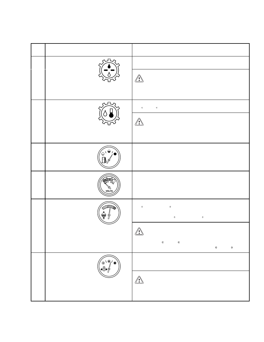
This amber light is ON when the oil filter is dirty and
has a restriction.
33
Transmission Oil
Filter Warning
Light
CAUTION
Do not continue to operate the vehicle when the
warning light is ON or damage to the Reach-
Stacker
®
may occur.
The red light is ON when the oil temperature is above
120 C (248 F).
34
Transmission
Oil Temperature
Warning Light
CAUTION
Do not continue to operate the vehicle when the
warning light is ON or damage to the Reach-
Stacker
®
may occur.
35
Fuel Gauge
This gauge indicates the amount of fuel in the tank.
36
Voltmeter
This gauge indicates the output of the alternator from
18 to 32 volts.
This gauge indicates engine coolant temperature, 40 to
120 C (104 to 248 F), when the key switch is in the ON
position. During normal operation, the gauge needle will
be between 70 to 90 C (158 to 194 F).
37
Coolant
Temperature
Gauge
CAUTION
Do NOT operate the vehicle when the temperature
is above 100 C (212 F). Engine shuts off automati-
cally when temperature reaches 105 C (221 F).
This gauge indicates the oil pressure in the engine from
0 to 5 bar (0 to 73 psi). Normal oil pressure at operating
temperature is 2 to 3.5 bar (29 to 51 psi).
38
Engine Oil
Pressure Gauge
CAUTION
Minimum oil pressure at idle speed is 0.8 bar
(12 psi). Engine may be derated or may shut down
when its oil pressure gets below 0.8 bar (12 psi).
7
Description
2200 SRM 1178
Table 1. Instrument Panel and Indicators (Continued)
Item
No.
Item
Function
The key switch has the following three positions:
• No. 1 Position: OFF position. De-energizes all electric
circuits except for the horn and rotating beacon.
• No. 2 Position: ON position. Energizes all electric cir-
cuits except the starter circuit. The key switch will be
in this position during normal operation.
• No. 3 Position: START position. Energizes the starter
motor for starting the engine. Push and hold the start
switch (item 21) while starting the engine. A spring
returns the key to position No. 2 (ON position) when
the key is released.
39
Key Switch
NOTE: There is a mechanical lockout that prevents the
key switch from being returned to the START position
without first being returned to the OFF position.
40
Parking Brake
Warning Light
The red light is ON when the parking brake is applied.
The red light is ON when the brake pressure is low for
operation.
41
Low Brake
Pressure Warning
Light
CAUTION
If the red light is ON, STOP operation of the Reach-
Stacker immediately. The red light stays ON until
the accumulator for the brake system is full.
Battery
Disconnect Lever
The battery disconnect switch operation is shown on the
label.
8
2200 SRM 1178
Description
Container Handler Controls
NOTE: For the location and description of the con-
tainer handler controls, see Figure 2 and Table 2.
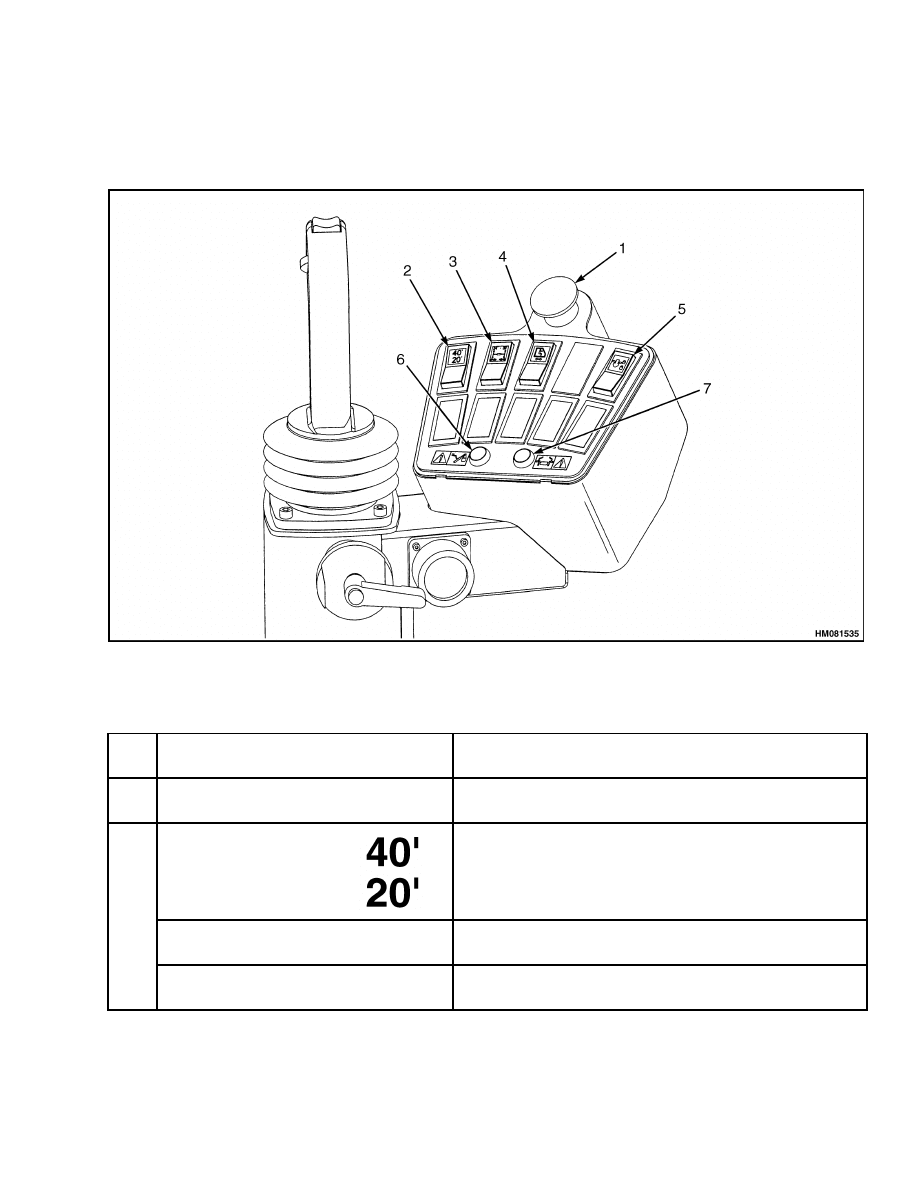
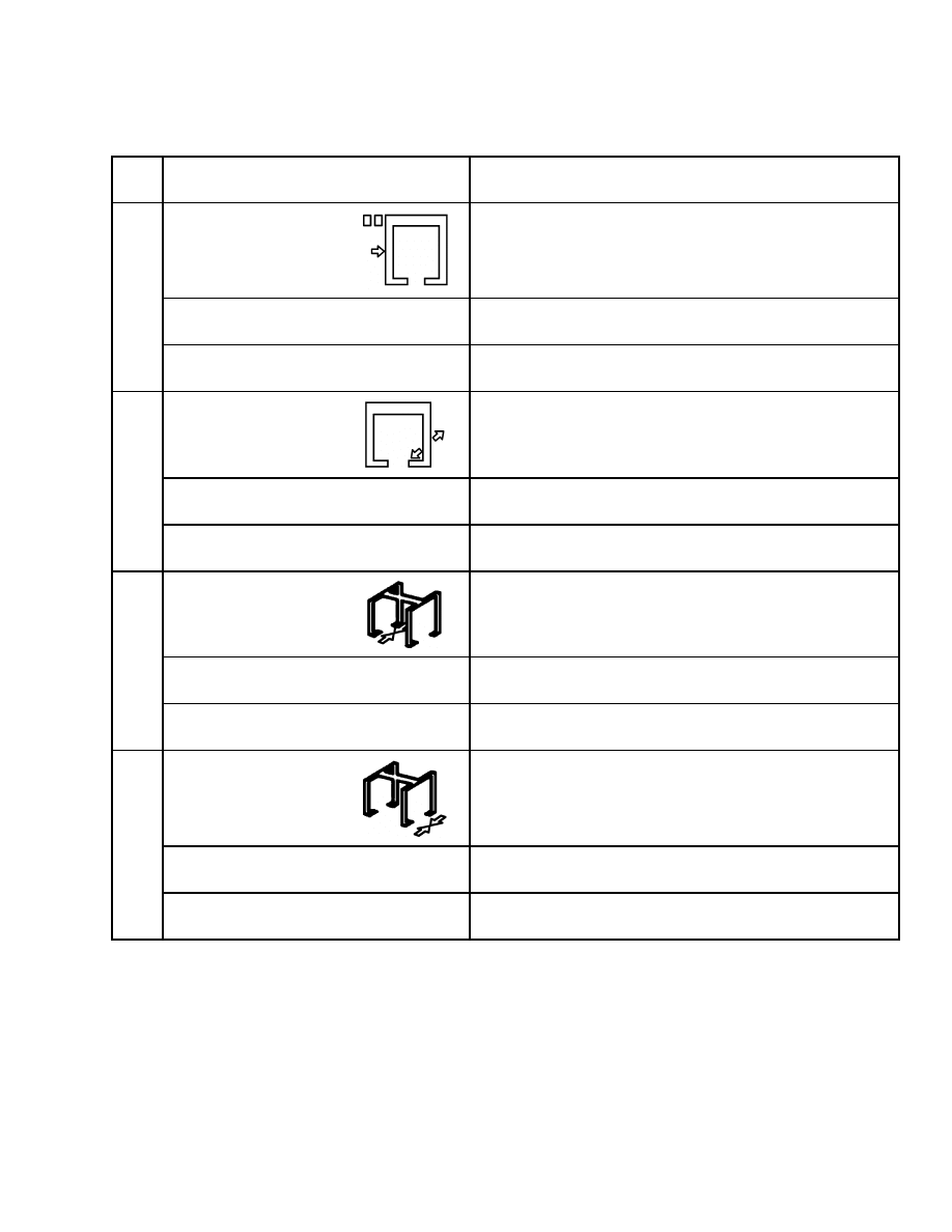
Figure 2. Container Handler Controls
Table 2. Container Handler Controls
Item
No.
Item
Function
1
Emergency Stop
Switch
Push knob to stop all functions of the spreader.
Container Selector
Button
40’ Position
Push the top of the rocker switch to select the 40’ position
of the spreader.
2
20’ Position
Push the bottom of the rocker switch to select the 20’
position of the spreader.
9
Description
2200 SRM 1178
Table 2. Container Handler Controls (Continued)
Item
No.
Item
Function
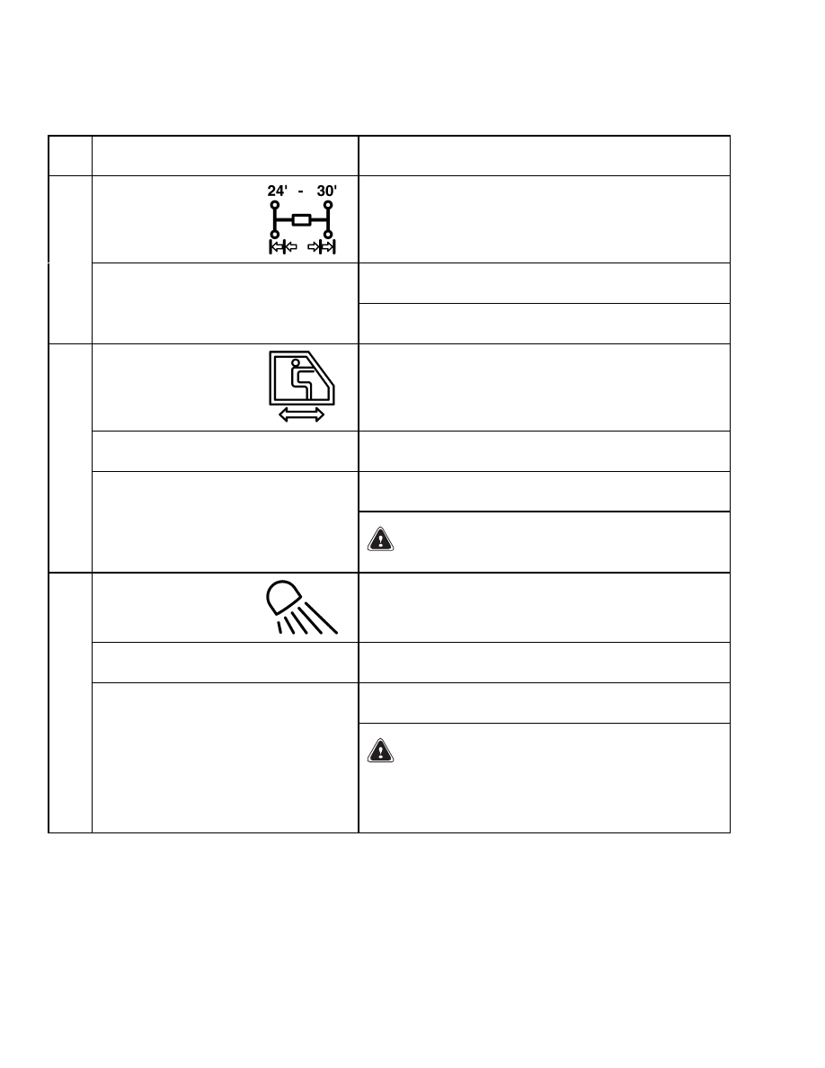
Container Selector
Button
Push and release the top of the rocker switch to select
the 30’ position of the spreader.
3
30’ Position
NOTE: Optional 24’ size by removing a stop-bar from the
hole on the spreader.
Optional Sliding cab
Forward
Push the top of the rocker switch to slide the cab
FORWARD. A buzzer will also sound.
Push the bottom of the rocker switch to slide the cab
BACKWARD. A buzzer will also sound.
4
Backward
WARNING
DO NOT position the cab under the load!
Twist lock Rocker
Switch
Engage
Push the top of the rocker switch to engage the twist
locks.
Push the bottom of the rocker switch to release the twist
locks.
5
Release
WARNING
The twist locks will not engage unless all four cor-
ners of the spreader are seated in the container.
The twist locks will NOT release unless the con-
tainer is set down.
10
2200 SRM 1178
Description
Table 2. Container Handler Controls (Continued)
Item
No.
Item
Function
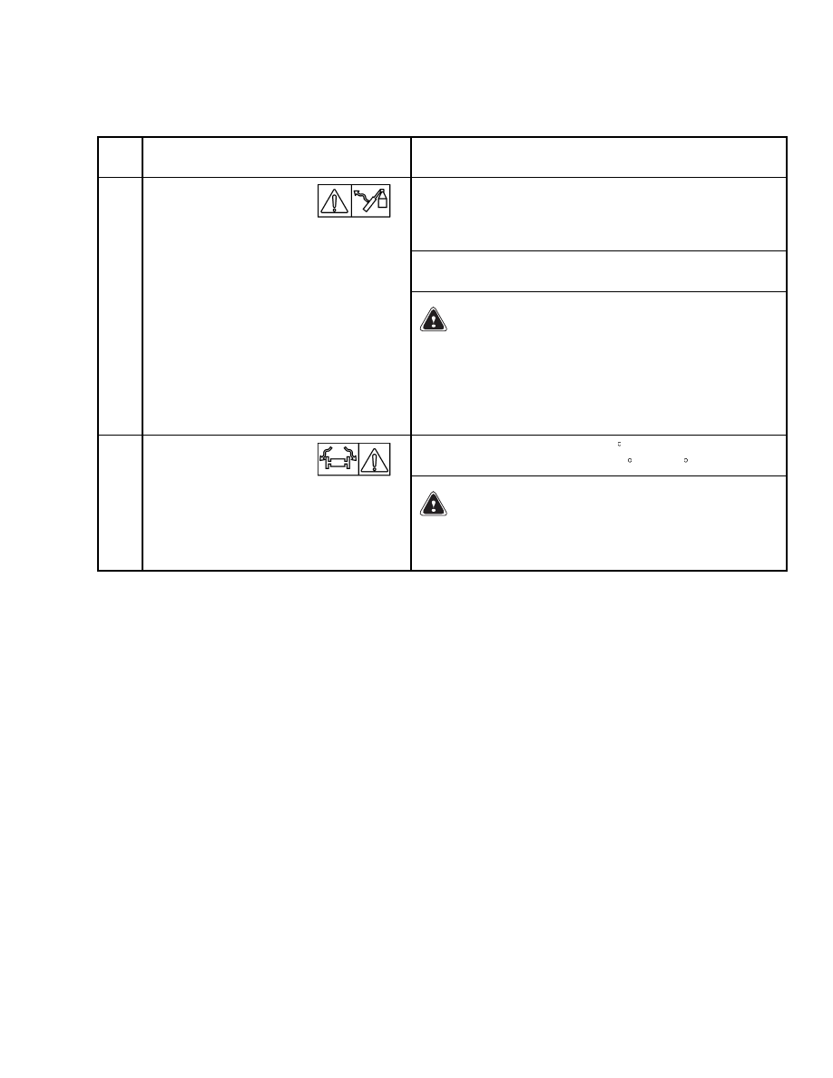
Push button to override the lock-out of boom tilting down
hydraulics caused by a malfunction in the twist lock
system or when the attachment is not connected to the
truck.
NOTE: Use the override button to handle/activate the
boom when the attachment is not connected to the truck.
6
Boom Lock-Out
Override Button
WARNING
Use the override button ONLY when twist lock sys-
tem malfunctions. Use the boom hydraulics to put
the container on a solid surface, another container,
or the ground.
Do NOT continue to operate the
ReachStacker when the twist locks do not operate
correctly.
Push button to override the 12 rotation limit. The
spreader can now rotate from -95 to +185 .
7
Rotator Override
Button
WARNING
Be careful when using the rotator override button.
The container can hit the boom or cab and cause an
accident or injury.
11
Description
2200 SRM 1178
Intermodal Handler Controls
NOTE: For the location and description of the inter-
modal handler controls, see Figure 3 and Table 3.
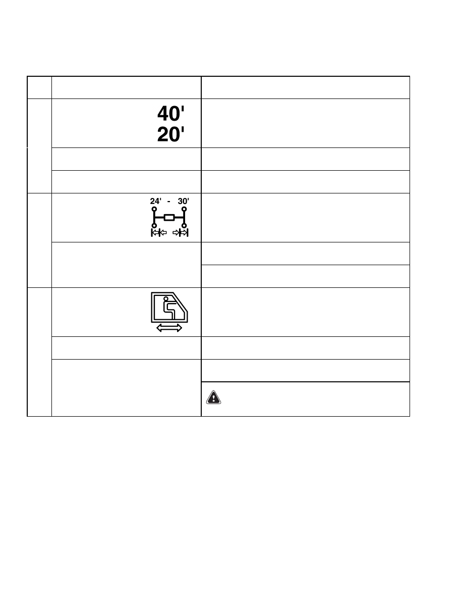
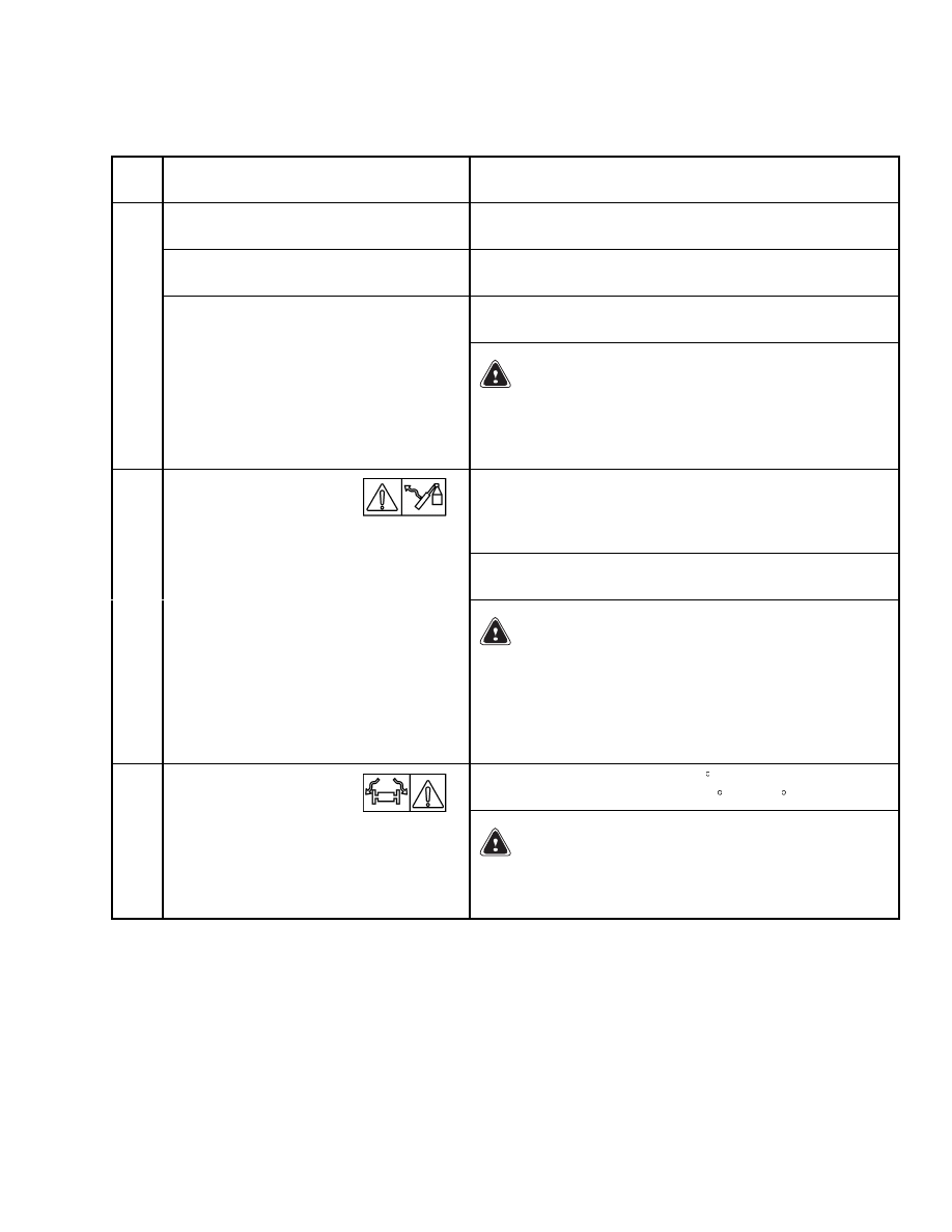
Figure 3. Intermodal Handler Controls
Table 3. Intermodal Handler Controls
Item
No.
Item
Function
1
Emergency Stop
Switch
Push knob to stop all functions of the spreader.
Rear Legs Selector
Button
Down
Push the top of the rocker switch to move the rear legs to
the VERTICAL position.
2
Up
Push the bottom of the rocker switch to move the rear
legs to the HORIZONTAL position.
12
2200 SRM 1178
Description
Table 3. Intermodal Handler Controls (Continued)
Item
No.
Item
Function
Rear Legs Pre-position
Selector Button
Approach
Push the top of the rocker switch to place the shoes of the
rear legs in position to approach the load.
3
Retract
Push the bottom of the rocker switch to retract the
pre-position of the rear legs.
Front Legs Selector
Button
Down
Push the top of the rocker switch to move the front legs
to the VERTICAL position.
4
Up
Push the bottom of the rocker switch to move the front
legs to the HORIZONTAL position.
Left Side Legs Selector
Button
Close
Push the top of the rocker switch to engage the left side
legs with the trailer.
5
Open
Push the bottom of the rocker switch to disengage the
left side legs from the trailer.
Right Side Legs
Selector Button
Close
Push the top of the rocker switch to engage the right side
legs with the trailer.
6
Open
Push the bottom of the rocker switch to disengage the
right side legs from the trailer.
13
Description
2200 SRM 1178
Table 3. Intermodal Handler Controls (Continued)
Item
No.
Item
Function
Container Selector
Button
40’ Position
Push the top of the rocker switch to select the 40’ position
of the spreader.
7
20’ Position
Push the bottom of the rocker switch to select the 20’
position of the spreader.
Container Selector
Button
Push and release the top of the rocker switch to select
the 30’ position of the spreader.
8
30’ Position
NOTE: Optional 24’ size by removing a stop-bar from the
hole on the spreader.
Optional Sliding cab
Forward
Push the top of the rocker switch to slide the cab
FORWARD. A buzzer will also sound.
Push the bottom of the rocker switch to slide the cab
BACKWARD. A buzzer will also sound.
9
Backward
WARNING
DO NOT position the cab under the load!
14
2200 SRM 1178
Description
Table 3. Intermodal Handler Controls (Continued)
Item
No.
Item
Function
Twist Lock Rocker
Switch
Engage
Push the top of the rocker switch to engage the twist
locks.
Push the bottom of the rocker switch to release the twist
locks.
10
Release
WARNING
The twist locks will not engage unless all four cor-
ners of the spreader are seated in the container.
The twist locks will NOT release unless the con-
tainer is set down.
Push button to override the lock-out of boom tilting down
hydraulics caused by a malfunction in the twist lock
system or when the attachment is not connected to the
truck.
NOTE: Use the override button to handle/activate the
boom when the attachment is not connected to the truck.
11
Boom Lock-Out
Override Button
WARNING
Use the override button ONLY when twist lock sys-
tem malfunctions. Use the boom hydraulics to put
the container on a solid surface, another container
or the ground.
Do NOT continue to operate the
ReachStacker when the twist locks do not operate
correctly.
Push button to override the 12 rotation limit. The
spreader can now rotate from -95 to +185 .
12
Rotator Override
Button
WARNING
Be careful when using the rotator override button.
The container can hit the boom or cab and cause an
accident or injury.
15
Description
2200 SRM 1178
3B6 Load Limiter System
NOTE: For the location and description of the inter-
modal handler controls, see Figure 4 and Table 4.
Figure 4. 3B6 Load Limiter System
16

2200 SRM 1178
Description
Table 4. 3B6 Load Limiter System
Item
No.
Item
Function
Displays information for the load sensing system. The display has
four rows as follows:
• The top row is a color bar, indicating safe, warning, and overload
conditions. See Item 2.
• The second row is a screen giving information about the current load.
This screen has 2 lines as follows:
The top line of the second row shows the percentage of load the truck
can lift. It is the default display. An alternate display (page) is
shown with the ENTER key (#5, page 1). It displays three groups of
information.
The bottom line of the second row shows the truck data. It is the
default display. It displays three groups of information. Pressing
ENTER shows the alternate display (page).
• The third row has symbols for the length, height, or angle of the
boom. The measurement information is on the line above the sym-
bol. Press ENTER key for each measurement. See Figure 4 items 4,
5, and 6.
• The fourth row is a row of keys used to change display values. See
items 4, 5, 6, and 7.
1-9
Alphanumeric Display
Screen
NOTE: WARNING MESSAGES ARE SHOWN ON THE DISPLAY
SCREEN. Please refer to 3B6 display pages for screen display infor-
mation.
The first line has a bar shown in three different colors as follows:
• Left side of graph is Green Zone:
Indicates load is within capacity limits of truck.
• Middle-right side of graph is Yellow Zone:
Indicates load is approaching capacity limits of truck. Limiter is in
caution zone, pre-alarm condition. Note warning triangle.
• Right side of graph is Red Zone:
Indicates load exceeds capacity limits of truck. Limiter alarm zone,
alarm sounds. Retract the boom or raise the boom, to shorten the
load center. Note stop symbol.
2
Percentage Bar Graph
NOTE: Do not lift the load if the load limiter is in the red zone.
17

Description
2200 SRM 1178
Table 4. 3B6 Load Limiter System (Continued)
Item
No.
Item
Function
Row two, bottom line, right side:
• Indicates the maximum liftable load in current position.
3
Maximum Liftable
Load/Boom Angle
NOTE: The maximum load, in metric tons or 1,000s of pounds allowed,
is indicated on the display screen above the Maximum Load symbol.
Press enter key (5) to display boom angle for 5 seconds.
4
Index Key
Selects mode of operation for display. Only used during calibration.
5
Enter Key
Shows operating mode of display. Pressing this key will display pages
of different data available for truck operation. There are 7 pages.
6
Buzzer Shutoff Key
Pressing this button shuts off the alarm buzzer. The buzzer
automatically resets after the alarm shuts off.
7
Set Key
This key is only used in calibrating the load sensing system.
Row three, middle:
Actual load radius, horizontal distance from the front of the tire to
the center of the load in meters or feet.
Press enter key (5). The actual lift height or the vertical distance from
the ground to the bottom of the twist locks is shown for 5 seconds.
8
Load Radius/Boom Height
Pushing on this button shows the lower and upper boom angles set
on the display screen.
The actual load, weight of container in metric tons or 1,000s of
pounds, is shown on the display screen above the actual load symbol.
9
Actual Load
NOTE: The actual load shows only the approximate weight of the con-
tainer. It is not a substitute for weighing the container to get the actual
weight.
Press enter key (5) to display boom length for 5 seconds.
10
Green Light
This light will come ON as a load system check when the truck is
started. It indicates load sensing systems conditions are functional
for proper truck operation.
11
Yellow Light
This light is ON when the truck is started, as a load system check. It
will be ON to indicate pre-alarm conditions during truck operation.
12
Red Light
This light will come ON as a load system check when the truck is
started. It will come ON to indicate alarm conditions during truck
operation.
18
2200 SRM 1178
Description
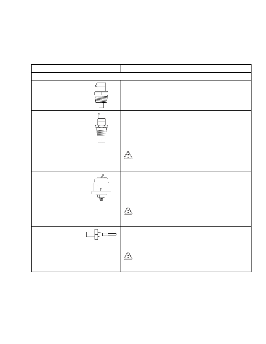
Senders
Table 5 describes the senders which send electronic
signals to the display panel.
Table 5. Sender Description
Item
Function
NOTE: For the locations of warning lights, see Table 1.
Water Temperature
Sender
The water temperature sender is mounted in the engine block
and senses the water temperature. If the water temperature
exceeds the specified temperature, the sender sends a signal to
the control panel and lights the coolant temperature indicator.
This signal also drives the coolant temperature gauge.
Transmission Oil
Temperature Sender
The transmission oil temperature sender unit is mounted
in the transmission oil sump and senses the transmission
fluid temperature. When the transmission temperature
exceeds system specifications, the sender sends a signal to the
instrument panel and lights the transmission oil temperature
warning light. This signal also drives the transmission oil
temperature gauge.
CAUTION
Do not continue to operate the ReachStacker when the
gauge indication is in the red area of the gauge.
Engine Oil Pressure
Sender
The engine oil pressure sender is located on the side of the
engine block and senses the engine oil pressure. If the oil
pressure drops lower than specifications, the sender sends a
signal to the control panel and lights the engine oil pressure
indicator. The engine oil pressure sender signal also drives
the engine oil pressure gauge.
CAUTION
Do not continue to operate the ReachStacker if the red
light is ON at engine speeds above idle.
Low Coolant Sender
The low coolant sender is mounted in the coolant system
radiator near the top of the tank. It senses the fluid level and,
when low, sends a signal to the control panel and lights the
engine low warning indicator.
CAUTION
Do not continue to operate the ReachStacker if the or-
ange light is ON during operation.
19
Description
2200 SRM 1178
Table 5. Sender Description (Continued)
Item
Function
NOTE: For the locations of warning lights, see Table 1.
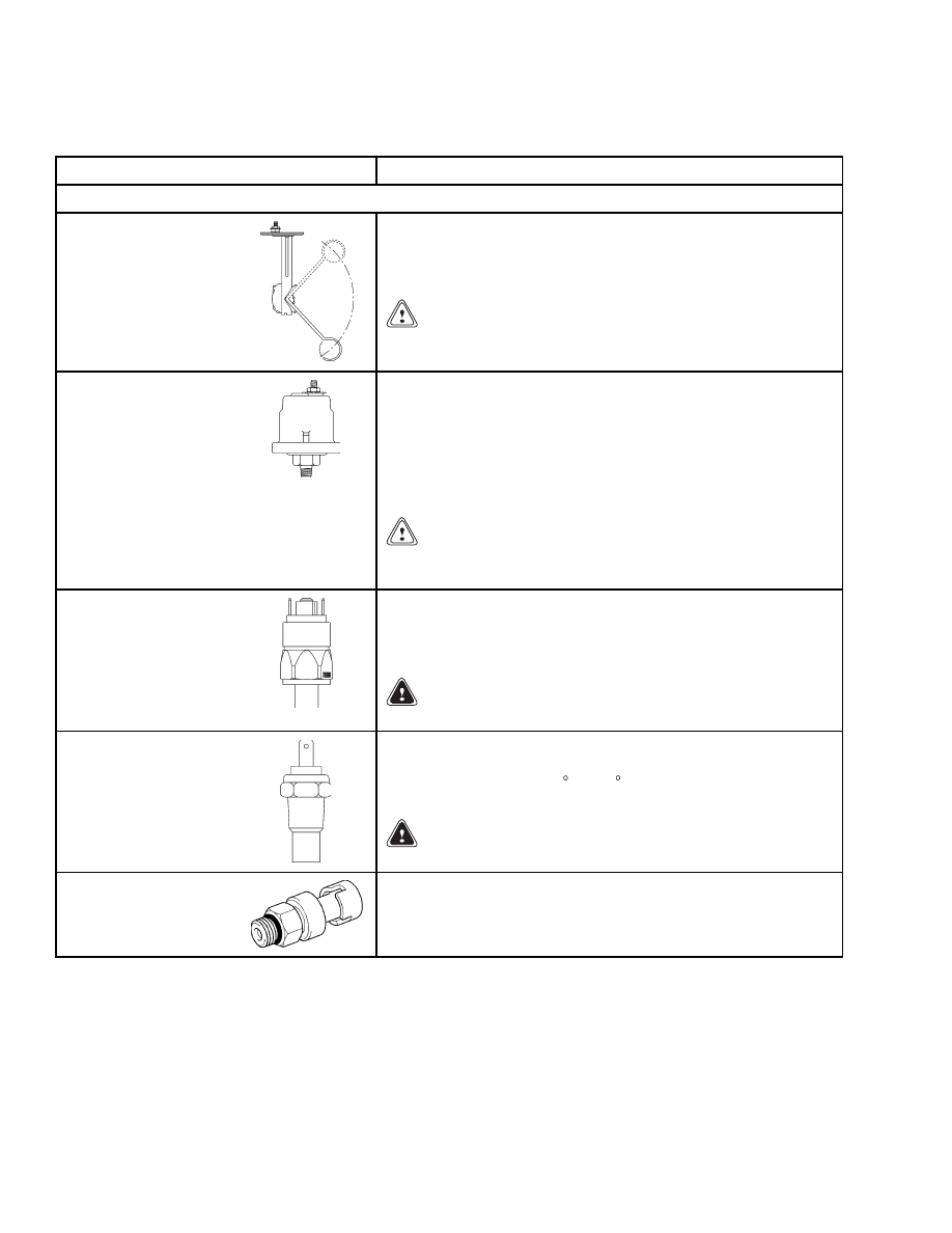
Fuel Level Sender
The fuel level sender is installed in the fuel tank and indicates
when the fuel is low. An internal float sends a signal to the
fuel level gauge to indicate the amount of fuel remaining in
the tank.
CAUTION
Do not continue to operate the ReachStacker if the or-
ange light is ON during operation.
Transmission Oil
Pressure Sender
The transmission oil pressure sender unit is mounted in the
transmission on the engine side and senses the transmission
fluid pressure. When the transmission oil pressure drops below
specifications, the sender sends a signal to the instrument
panel and lights the transmission oil pressure warning
light. The transmission oil pressure sender also drives the
transmission oil pressure gauge.
CAUTION
Do not continue to operate the ReachStacker when the
red light is ON at engine speeds above idle.
Low Pressure Sender
The low pressure sender senses the brake system pressure.
When pressure drops below specified value, the sender sends
a signal to the instrument panel and lights the low pressure
warning light 14.
WARNING
Never operate a truck with a brake malfunction.
Brake Temperature
Sender
The brake temperature senders are mounted in the wheel
hubs and sense the brake fluid temperature. If the fluid
temperature exceeds 110 C (230 F), the senders send a signal
to the instrument panel and lights warning light 15.
WARNING
Never operate a truck with a brake malfunction.
Intake Manifold
Pressure Sensor
This is an active sensor with an output between 0 and 5 volts.
The ECM will recognize the output to be valid if it is between
0.5 volts representing 52 kPa (8 psi) and 4.5 volts representing
306 kPa (44 psi).
20
2200 SRM 1178
Instrument Panel Component Replacement
Table 5. Sender Description (Continued)
Item
Function
NOTE: For the locations of warning lights, see Table 1.
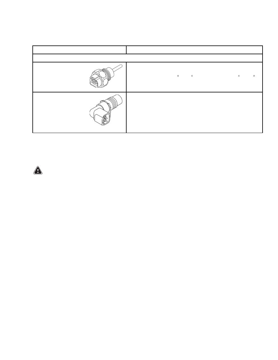
Intake Manifold
Temperature Sensor
This is a thermistor-type sensor with an output between 0 and
5 volts. The ECM will recognize the output to be valid if it is
between 0.2 volts at -40 C (-40 F) and 4.9 volts at 150 C (302 F).
Sensor diagnostics will detect a fault if the input voltage is
outside this range for more than 2 seconds continuously.
Crankshaft Position
Sensor
This is a magnetic-type sensor that measures both crankshaft
speed and position. The sensor will measure speeds above
246 rpm when the output will be greater than 0.4 volts peak
to peak. The sensor detects the passing of teeth on a wheel.
These teeth are spaced at 1/36 intervals of the wheel. One
tooth is missing to facilitate the position measurement. There
are a total of 36 teeth.
Instrument Panel Component Replacement
GENERAL
WARNING
Before replacing any components, fully lower
all parts of the mast and tilt it forward until the
tips of the forks touch the ground. This action
will prevent the mast from lowering suddenly
if the control lever is accidently moved.
ALWAYS disconnect the battery and remove op-
erator key before replacing components.
Never have any metal on your fingers, arms, or
neck. These metal items can accidentally make
an electrical connection and may cause an in-
jury.
Meters, display panels, most indicators, and senders
are not repairable items. The most accurate and usu-
ally easiest check for proper operation of individual
meters, indicators, or senders is direct replacement.
The most common cause of failure is poor connec-
tions or damaged or improper wiring and not the me-
ter indicator or sender. This section only has the re-
placement procedures. Before a meter, display panel,
indicator, or sender is replaced, make the following
checks:
1.
Check that other meters and electrical circuits
operate correctly.
2.
Check that the battery is fully charged and has
a good ground and cable terminals are clean and
tight.
3.
Check that the wiring and connections to meter,
indicator, or sender are tight and in good condi-
tion.
INSTRUMENT PANEL
Remove
NOTE: None of the electrical components can be re-
paired. All malfunctioning components must be re-
placed.
1.
Disconnect ground lead of battery.
2.
Remove the four screws from front panel.
3.
Carefully lift the front panel to have access to the
back inner side of the front panel.
4.
Put tags on the wires for correct identification
during installation.
5.
Remove the wires from the meter terminals.
NOTE: The indicators, switches, and gauges are as-
sembled as a terminal and if one function has a mal-
function, you must replace a complete terminal.
6.
Remove the terminal that is malfunctioning.
21

Instrument Panel Component Replacement
2200 SRM 1178
Install
1.
Install a new terminal.
2.
Connect the wires using the tag information.
CAUTION
Use caution when installing the front panel to
avoid damage to the wires.
3.
Install the front panel and install the four screws
at the front panel.
4.
Connect the ground lead of battery.
5.
Check if all functions work correctly.
CONTAINER/INTERMODAL HANDLER
CONTROLS
Remove
1.
Disconnect the ground lead of battery.
NOTE: The connector is held in place with a mount-
ing cap. To disconnect the connector, turn the mount-
ing cap counterclockwise and pull slightly to remove
the connector.
2.
Disconnect the connector at the backside of the
handler controls.
3.
Remove the three socket head capscrews from
the back cover.
4.
Remove the back cover.
NOTE: Switch connectors are already numbered for
identification. Tag the connector or make a note of
the correct identification number.
5.
Disconnect the switch connector from the switch
with the malfunction.
6.
Remove the switch by pushing it out of the front
panel.
Install
1.
Install the new switch by pressing it firmly into
the hole of the front panel.
2.
Connect the correct switch connector.
3.
Connect the ground lead of battery.
4.
Check for correct functions.
5.
Install the back cover and three socket head cap-
screws.
3B6 Load Limiter System
Replace
NOTE: The load limiter system is not a repairable
part. Replace complete load limiter system.
1.
Disconnect the ground lead of battery.
2.
Disconnect connector at the backside of the load
limiter system.
3.
Remove two screws that hold the load limiter sys-
tem to the bracket.
4.
Remove and replace the load limiter system.
5.
Install two screws that hold the load limiter sys-
tem to the bracket.
6.
Connect the connector at the backside of the load
limiter system.
7.
Connect the ground lead of battery.
8.
Check that the functions of the load limiter sys-
tem work correctly.
22
2200 SRM 1178
Sender Replacement
Sender Replacement
FUEL LEVEL SENDER
WARNING
Before replacing any components, fully lower
the boom. This action will prevent the boom
from lowering suddenly if the control lever is
accidently moved.
ALWAYS disconnect the battery and remove op-
erator key before replacing components.
Never have any metal on your fingers, arms, or
neck. These metal items can accidentally make
an electrical connection and may cause an in-
jury.
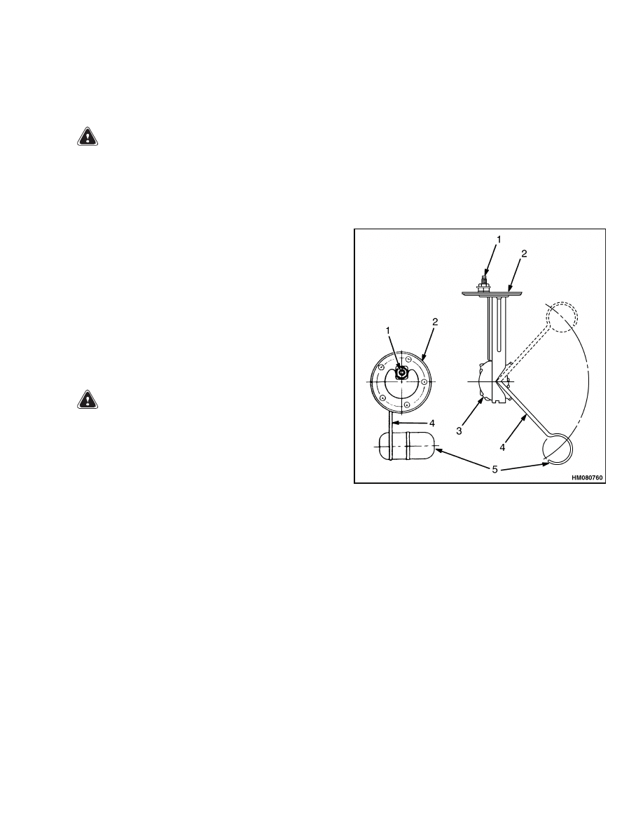
The fuel level sending unit is mounted to fuel tank
surface (usually top surface) with screws through
the sender plate and gasket. See Figure 5. Correct
sender operation and screw hole alignment can only
be obtained with plate mounted in one position.
Replace sender as follows:
WARNING
All fuel vapors are extremely explosive. Do not
have sparks or flames around vehicles or fuel
storage and service areas. Verify there is no
source of open flame or sparks in the vicinity.
Use caution to prevent sparks from tools.
1.
Turn key switch to OFF position. Disconnect
battery positive cable at battery. Install a lock
or tag on connector to prevent connection.
2.
Disconnect sender wire at sender.
3.
Remove screws that fasten sender plate to tank.
4.
Remove sender.
5.
Carefully install new sender. Use a new gasket.
6.
Verify screw holes are aligned and install screws.
Tighten screws enough to partially compress gas-
ket to prevent leaks.
7.
Remove tape from wire connector and install con-
nector on sender terminal.
1.
ELECTRICAL
TERMINAL
2.
PLATE
3.
SENDER UNIT
4.
FLOAT ARM
5.
FLOAT
Figure 5. Fuel Level Sender
23
Sender Replacement
2200 SRM 1178
PRESSURE SENDER
NOTE: If applicable, replace O-ring when replacing
sender.
1.
Turn key switch to OFF position.
2.
Disconnect electrical connector.
3.
Remove pressure sender. See Figure 6.
4.
Install new pressure sender.
5.
Connect electrical connector.
6.
Check if sender is functioning correctly.
Figure 6. Pressure Sender
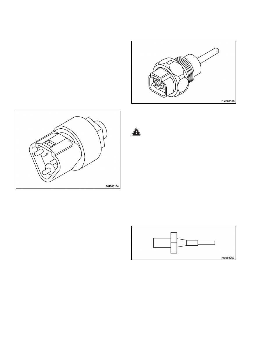
TEMPERATURE SENDER
NOTE: If applicable, replace O-ring when replacing
sender.
1.
Turn key switch to OFF position.
2.
Disconnect electrical connector.
3.
Remove temperature sender. See Figure 7.
4.
Install new temperature sender.
5.
Connect electrical connector.
6.
Check if sender is functioning correctly.
Figure 7. Temperature Sender
LOW COOLANT SENDER
WARNING
High temperature risk. Radiator temperature
may be high and radiator may be pressurized.
NOTE: Verify system fluid is drained so the level is
below sender to prevent leakage when sender is re-
moved.
1.
Turn key switch to OFF position.
2.
Disconnect sender wire. See Figure 8.
3.
Turn sender counterclockwise and remove.
4.
Install a new sender.
Use Teflon tape.
Turn
clockwise and tighten. Torque 5.6 ±0.6 N•m (50
±5 lbf in).
5.
Connect sender wire.
Figure 8. Low Coolant Sender
24
2200 SRM 1178
Sender Replacement
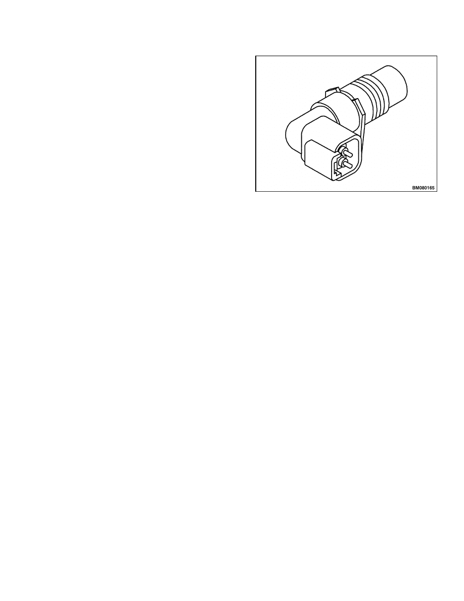
CRANKSHAFT POSITION SENSOR
NOTE: If applicable, replace O-ring when replacing
sensor.
1.
Turn key switch to OFF position.
2.
Disconnect electrical connector.
3.
Remove crankshaft position sensor. See Figure 9.
4.
Install new crankshaft position sensor.
5.
Connect electrical connector.
6.
Check if sender is functioning correctly.
Figure 9. Crankshaft Position Sensor
25

NOTES
____________________________________________________________
____________________________________________________________
____________________________________________________________
____________________________________________________________
____________________________________________________________
____________________________________________________________
____________________________________________________________
____________________________________________________________
____________________________________________________________
____________________________________________________________
____________________________________________________________
____________________________________________________________
____________________________________________________________
____________________________________________________________
____________________________________________________________
____________________________________________________________
____________________________________________________________
____________________________________________________________
____________________________________________________________
____________________________________________________________
26


TECHNICAL PUBLICATIONS
2200 SRM 1178
3/05 Printed in United Kingdom
Document Outline
- toc
- tables
Wyszukiwarka
Podobne podstrony:
897961 2200SRM0647 (03 2005) UK EN
1586982 0100SRM1177 (03 2005) UK EN
1589731 2200SRM1184 (03 2005) UK EN
897825 2200SRM0596 (03 2005) UK EN
897953 1600SRM0639 (03 2005) UK EN
1598459 1900SRM1213 (03 2005) UK EN
897956 1900SRM0642 (03 2005) UK EN
897963 4500SRM0649 (03 2005) UK EN
897435 2200SRM0473 (03 1994) UK EN
1554634 2200SRM1078 (07 2005) UK EN
1573930 0600SRM1172 (03 2005) UK EN
897345 1400SRM0413 (03 2005) UK EN
1531815 1800SRM1040 (03 2005) UK EN
1468474 2200SRM0756 (07 2005) UK EN
więcej podobnych podstron