BRITISH STANDARD
BS EN
1993-1-5:2006
Eurocode 3 — Design of
steel structures —
Part 1-5: Plated structural elements
ICS 91.010.30; 91.080.10
12&23<,1*:,7+287%6,3(50,66,21(;&(37$63(50,77('%<&23<5,*+7/$:
corrigendum
April 2009
Incorporating
Licensed copy: BSI USER 06 Document Controller, Midmac Contracting Co. W.L.L, Version correct as of 26/05/2010
13:22, (c) BSI

National foreword
This British Standard is the UK implementation of EN 1993-1-5:2006,
incorporating corrigendum April 2009.
The start and finish of text introduced or altered by corrigendum is indicated
in the text by tags. Tags indicating changes to CEN text carry the number of
the CEN corrigendum. For example, text altered by April 2009 corrigendum is
indicated by ˆ‰.
The structural Eurocodes are divided into packages by grouping Eurocodes for
each of the main materials: concrete, steel, composite concrete and steel,
timber, masonry and aluminium; this is to enable a common date of
withdrawal (DOW) for all the relevant parts that are needed for a particular
design. The conflicting national standards will be withdrawn at the end of the
co-existence period, after all the EN Eurocodes of a package are available.
Following publication of the EN, there is a period allowed for national
calibration during which the National Annex is issued, followed by a
co-existence period of a maximum three years. During the co-existence period
Member States are encouraged to adapt their national provisions. At the end
of this co-existence period, the conflicting parts of national standard(s) will be
withdrawn.
In the UK, the primary corresponding national standards are:
BS 449-2:1969, Specification for the use of structural steel in building. Metric
units
BS 5400-3:2000, Steel, concrete and composite bridges. Code of practice for
design of steel bridges
BS 5950-1:2000, Structural use of steelwork in building. Code of practice for
design. Rolled and welded sections
BS EN 1993-1-5 partially supersedes BS 449-2, BS 5400-3, and BS 5950-1,
which will be withdrawn by March 2010.
The UK participation in its preparation was entrusted by Technical Committee
B/525, Building and civil engineering structures, to Subcommittee B/525/31,
Structural use of steel.
A list of organizations represented on this subcommittee can be obtained on
request to its secretary.
Where a normative part of this EN allows for a choice to be made at the
national level, the range and possible choice will be given in the normative text
as Recommended Values, and a note will qualify it as a Nationally Determined
Parameter (NDP). NDPs can be a specific value for a factor, a specific level or
class, a particular method or a particular application rule if several are
proposed in the EN.
To enable EN 1993-1-5 to be used in the UK, the NDPs have been published in
a National Annex, which has been issued separately by BSI.
This publication does not purport to include all the necessary provisions of a
contract. Users are responsible for its correct application.
Compliance with a British Standard cannot confer immunity from
legal obligations.
BS EN 1993-1-5:2006
This British Standard was
published under the authority
of the Standards Policy and
Strategy Committee
on 30 November 2006
© BSI 2010
ISBN 978 0 580 66395 6
Amendments/corrigenda issued since publication
Date
Comments
28 February 2010 Implementation of CEN corrigendum April 2009
Licensed copy: BSI USER 06 Document Controller, Midmac Contracting Co. W.L.L, Version correct as of 26/05/2010
13:22, (c) BSI

EUROPEAN STANDARD
NORME EUROPÉENNE
EUROPÄISCHE NORM
EN 1993-1-5
October 2006
ICS 91.010.30; 91.080.10
Supersedes ENV 1993-1-5:1997
English Version
Eurocode 3 - Design of steel structures - Part 1-5: Plated
structural elements
Eurocode 3 - Calcul des structures en acier - Partie 1-5:
Plaques planes
Eurocode 3 - Bemessung und konstruktion von Stahlbauten
- Teil 1-5: Plattenbeulen
This European Standard was approved by CEN on 13 January 2006.
CEN members are bound to comply with the CEN/CENELEC Internal Regulations which stipulate the conditions for giving this European
Standard the status of a national standard without any alteration. Up-to-date lists and bibliographical references concerning such national
standards may be obtained on application to the Central Secretariat or to any CEN member.
This European Standard exists in three official versions (English, French, German). A version in any other language made by translation
under the responsibility of a CEN member into its own language and notified to the Central Secretariat has the same status as the official
versions.
CEN members are the national standards bodies of Austria, Belgium, Cyprus, Czech Republic, Denmark, Estonia, Finland, France,
Germany, Greece, Hungary, Iceland, Ireland, Italy, Latvia, Lithuania, Luxembourg, Malta, Netherlands, Norway, Poland, Portugal, Romania,
Slovakia, Slovenia, Spain, Sweden, Switzerland and United Kingdom.
EUROPEAN COMMITTEE FOR STANDARDIZATION
C O M I T É E U R O P É E N D E N O R M A L I S A T I O N
E U R O P Ä IS C H E S K O M IT E E FÜ R N O R M U N G
Management Centre: rue de Stassart, 36 B-1050 Brussels
© 2006 CEN
All rights of exploitation in any form and by any means reserved
worldwide for CEN national Members.
Ref. No. EN 1993-1-5:2006: E
Incorporating corrigendum April 2009
Licensed copy: BSI USER 06 Document Controller, Midmac Contracting Co. W.L.L, Version correct as of 26/05/2010
13:22, (c) BSI

2
Content
Page
1
Introduction
5
1.1
Scope
5
1.2
Normative references
5
1.3
Terms and definitions
5
1.4
Symbols
6
2
Basis of design and modelling
7
2.1
General
7
2.2
Effective width models for global analysis
7
2.3
Plate buckling effects on uniform members
7
2.4
Reduced stress method
8
2.5
Non uniform members
8
2.6
Members with corrugated webs
8
3
Shear lag in member design
9
3.1
General
9
3.2
Effective
s
width for elastic shear lag
9
3.3
Shear lag at the ultimate limit state
12
4
Plate buckling effects due to direct stresses at the ultimate limit state
13
4.1
General
13
4.2
Resistance to direct stresses
13
4.3
Effective cross section
13
4.4
Plate elements without longitudinal stiffeners
15
4.5
Stiffened plate elements with longitudinal stiffeners
18
4.6
Verification
21
5
Resistance to shear
21
5.1
Basis
21
5.2
Design resistance
22
5.3
Contribution from the web
22
5.4
Contribution from flanges
25
5.5
Verification
25
6
Resistance to transverse forces
25
6.1
Basis
25
6.2
Design resistance
26
6.3
Length of stiff bearing
26
6.4
Reduction factor
χ
F
for effective length for resistance
27
6.5
Effective loaded length
27
6.6
Verification
28
7
Interaction
28
7.1
Interaction between shear force, bending moment and axial force
28
7.2
Interaction between transverse force, bending moment and axial force
29
8
Flange induced buckling
29
9
Stiffeners and detailing
30
9.1
General
30
9.2
Direct stresses
30
9.3
Shear
34
9.4
Transverse loads
35
10
Reduced stress method
36
Annex A (informative) Calculation of critical stresses for stiffened plates
38
BS EN 1993-1-5:2006
EN 1993-1-5:2006 (E)
Licensed copy: BSI USER 06 Document Controller, Midmac Contracting Co. W.L.L, Version correct as of 26/05/2010
13:22, (c) BSI

3
Annex B (informative) Non uniform members
43
Annex C (informative) Finite Element Methods of Analysis (FEM)
45
Annex D (informative) Plate girders with corrugated webs
50
Annex E (normative) Alternative methods for determining effective cross sections
53
BS EN 1993-1-5:2006
EN 1993-1-5:2006 (E)
Licensed copy: BSI USER 06 Document Controller, Midmac Contracting Co. W.L.L, Version correct as of 26/05/2010
13:22, (c) BSI

4
Foreword
This European Standard EN 1993-1-5,, Eurocode 3: Design of steel structures Part 1.5: Plated structural
elements, has been prepared by Technical Committee CEN/TC250 « Structural Eurocodes », the Secretariat
of which is held by BSI. CEN/TC250 is responsible for all Structural Eurocodes.
This European Standard shall be given the status of a National Standard, either by publication of an identical
text or by endorsement, at the latest by April 2007 and conflicting National Standards shall be withdrawn
at latest by March 2010.
This Eurocode supersedes ENV 1993-1-5.
According to the CEN-CENELEC Internal Regulations, the National Standard Organizations of the
following countries are bound to implement this European Standard: Austria, Belgium, Cyprus, Czech
Republic, Denmark, Estonia, Finland, France, Germany, Greece, Hungary, Iceland, Ireland, Italy, Latvia,
Lithuania, Luxembourg, Malta, Netherlands, Norway, Poland, Portugal, Romania, Slovakia, Slovenia, Spain,
Sweden, Switzerland and United Kingdom.
National annex for EN 1993-1-5
This standard gives alternative procedures, values and recommendations with notes indicating where national
choices may have to be made. The National Standard implementing EN 1993-1-5 should have a National
Annex containing all Nationally Determined Parameters to be used for the design of steel structures to be
constructed in the relevant country.
National choice is allowed in EN 1993-1-5 through:
–
2.2(5)
–
3.3(1)
–
4.3(6)
–
5.1(2)
–
6.4(2)
–
8(2)
–
9.1(1)
–
9.2.1(9)
–
10(1)
–
10(5)
–
C.2(1)
–
C.5(2)
–
C.8(1)
–
C.9(3)
–
D.2.2(2)
BS EN 1993-1-5:2006
EN 1993-1-5:2006 (E)
Licensed copy: BSI USER 06 Document Controller, Midmac Contracting Co. W.L.L, Version correct as of 26/05/2010
13:22, (c) BSI

5
1 Introduction
1.1 Scope
(1)
EN 1993-1-5 gives design requirements of stiffened and unstiffened plates which are subject to in-
plane forces.
(2)
Effects due to shear lag, in-plane load introduction and plate buckling for I-section girders and box
girders are covered. Also covered are plated structural components subject to in-plane loads as in tanks and
silos. The effects of out-of-plane loading are outside the scope of this document.
NOTE 1: The rules in this part complement the rules for class 1, 2, 3 and 4 sections, see EN 1993-1-1.
NOTE 2: For the design of slender plates which are subject to repeated direct stress and/or shear and also
fatigue due to out-of-plane bending of plate elements (breathing) see EN 1993-2 and EN 1993-6.
NOTE 3: For the effects of out-of-plane loading and for the combination of in-plane effects and out-of-plane
loading effects see EN 1993-2 and EN 1993-1-7.
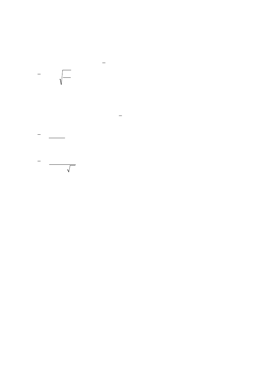
NOTE 4: Single plate elements may be considered as flat where the curvature radius r satisfies:
t
a
r
2
≥
(1.1)
where a is the panel width
t
is the plate thickness
1.2 Normative references
(1)
This European Standard incorporates, by dated or undated reference, provisions from other
publications. These normative references are cited at the appropriate places in the text and the publications
are listed hereafter. For dated references, subsequent amendments to or revisions of any of these publications
apply to this European Standard only when incorporated in it by amendment or revision. For undated
references the latest edition of the publication referred to applies.
EN 1993-1-1
Eurocode 3 :Design of steel structures: Part 1-1: General rules and rules for buildings
1.3 Terms and definitions
For the purpose of this standard, the following terms and definitions apply:
1.3.1
elastic critical stress
stress in a component at which the component becomes unstable when using small deflection elastic theory
of a perfect structure
1.3.2
membrane stress
stress at mid-plane of the plate
1.3.3
gross cross-section
the total cross-sectional area of a member but excluding discontinuous longitudinal stiffeners
1.3.4
effective cross-section and effective width
the gross cross-section or width reduced for the effects of plate buckling or shear lag or both; to distinguish
between their effects the word “effective” is clarified as follows:
“effective
p
“ denotes effects of plate buckling
BS EN 1993-1-5:2006
EN 1993-1-5:2006 (E)
Licensed copy: BSI USER 06 Document Controller, Midmac Contracting Co. W.L.L, Version correct as of 26/05/2010
13:22, (c) BSI

6
“effective
s
“ denotes effects of shear lag
“effective“ denotes effects of plate buckling and shear lag
1.3.5
plated structure
a structure built up from nominally flat plates which are connected together; the plates may be stiffened or
unstiffened
1.3.6
stiffener
a plate or section attached to a plate to resist buckling or to strengthen the plate; a stiffener is denoted:
–
longitudinal if its direction is parallel to the member;
–
transverse if its direction is perpendicular to the member.
1.3.7
stiffened plate
plate with transverse or longitudinal stiffeners or both
1.3.8
subpanel
unstiffened plate portion surrounded by flanges and/or stiffeners
1.3.9
hybrid girder
girder with flanges and web made of different steel grades; this standard assumes higher steel grade in
flanges compared to webs
1.3.10
sign convention
unless otherwise stated compression is taken as positive
1.4 Symbols
(1)
In addition to those given in EN 1990 and EN 1993-1-1, the following symbols are used:
A
sℓ
total area of all the longitudinal stiffeners of a stiffened plate;
A
st
gross cross sectional area of one transverse stiffener;
A
eff
effective cross sectional area;
A
c,eff
effective
p
cross sectional area;
A
c,eff,loc
effective
p
cross sectional area for local buckling;
a
length of a stiffened or unstiffened plate;
b
width of a stiffened or unstiffened plate;
b
w
;
b
eff
effective
s
width for elastic shear lag;
F
Ed
design transverse force;
h
w
clear web depth between flanges;
L
eff
effective length for resistance to transverse forces, see 6;
M
f.Rd
design plastic moment of resistance of a cross-section consisting of the flanges only;
M
pl.Rd
design plastic moment of resistance of the cross-section (irrespective of cross-section class);
M
Ed
design bending moment;
N
Ed
design axial force;
t
thickness of the plate;
ˆ
‰
BS EN 1993-1-5:2006
EN 1993-1-5:2006 (E)
clear width between welds for welded sections or between ends of radii for rolled sections
Licensed copy: BSI USER 06 Document Controller, Midmac Contracting Co. W.L.L, Version correct as of 26/05/2010
13:22, (c) BSI

7
V
Ed
design shear force including shear from torque;
W
eff
effective elastic section modulus;
β
effective
s
width factor for elastic shear lag;
(2)
Additional symbols are defined where they first occur.
2 Basis of design and modelling
2.1 General
(1)P The effects of shear lag and plate buckling shall be taken into account at the ultimate, serviceability or
fatigue limit states.
NOTE: Partial factors
γ
M0
and
γ
M1
used in this part are defined for different applications in the National
Annexes of EN 1993-1 to EN 1993-6.
2.2 Effective width models for global analysis
(1)P The effects of shear lag and of plate buckling on the stiffness of members and joints shall be taken into
account in the global analysis.
(2)
The effects of shear lag of flanges in global analysis may be taken into account by the use of an
effective
s
width. For simplicity this effective
s
width may be assumed to be uniform over the length of the
span.
(3)
For each span of a member the effective
s
width of flanges should be taken as the lesser of the full
width and L/8 per side of the web, where L is the span or twice the distance from the support to the end of a
cantilever.
(4)
The effects of plate buckling in elastic global analysis may be taken into account by effective
p
cross
sectional areas of the elements in compression, see 4.3.
(5)
For global analysis the effect of plate buckling on the stiffness may be ignored when the effective
p
cross-sectional area of an element in compression is larger than
ρ
lim
times the gross cross-sectional area of
the same element.
NOTE 1: The parameter
ρ
lim
may be given in the National Annex. The value
ρ
lim
= 0,5 is recommended.
NOTE 2: For determining the stiffness when (5) is not fulfilled, see Annex E.
2.3 Plate buckling effects on uniform members
(1)
Effective
p
width models for direct stresses, resistance models for shear buckling and buckling due to
transverse loads as well as interactions between these models for determining the resistance of uniform
members at the ultimate limit state may be used when the following conditions apply:
–
panels are rectangular and flanges are parallel;
–
the diameter of any unstiffened open hole or cut out does not exceed 0,05b, where b is the width of the
panel.
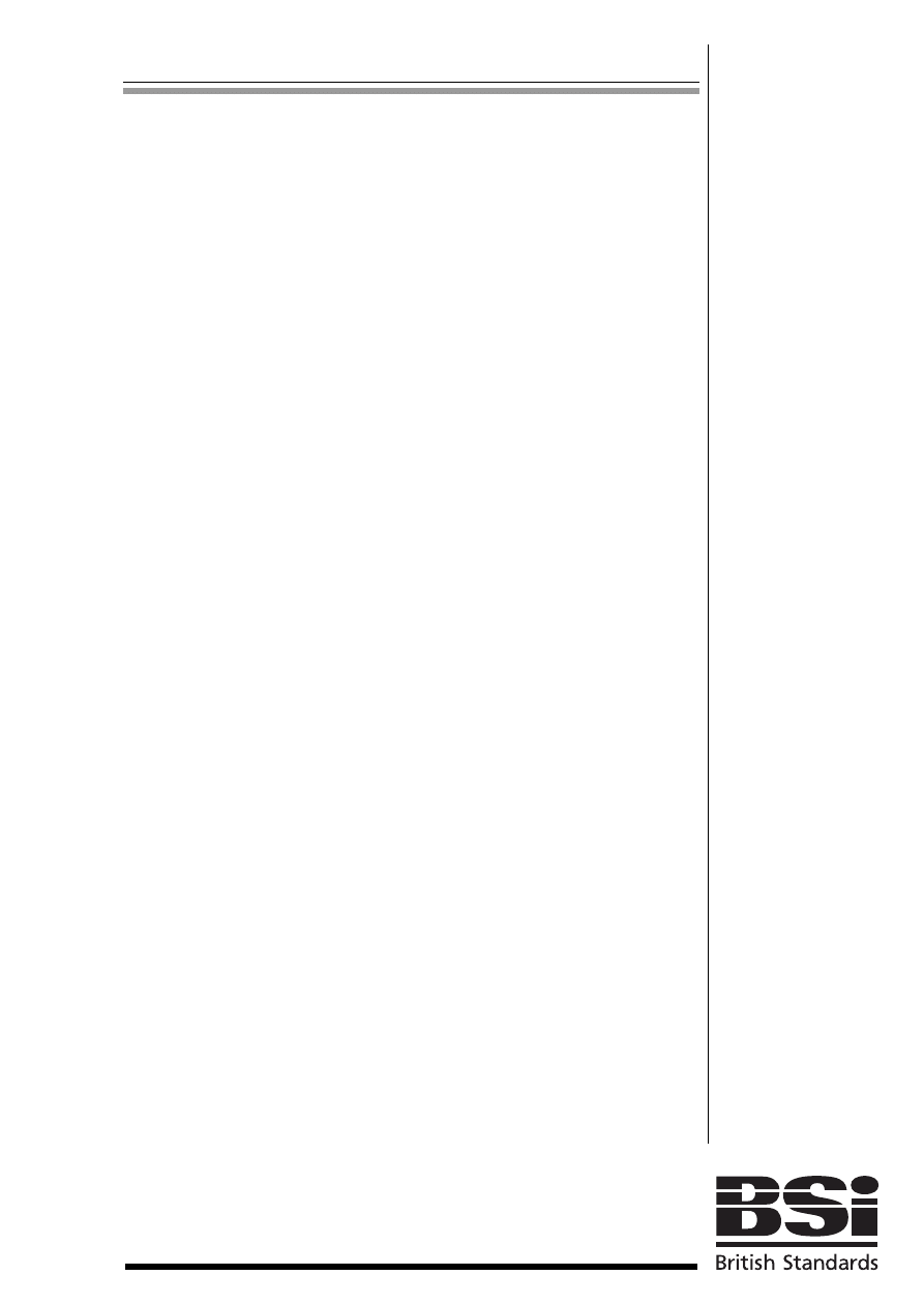
NOTE: The rules may apply to non rectangular panels provided the angle
α
limit
(see Figure 2.1) is not greater
than 10 degrees. If α
limit
exceeds 10, panels may be assessed assuming it to be a rectangular panel based on the
larger of b
1
and b
2
of the panel.
BS EN 1993-1-5:2006
EN 1993-1-5:2006 (E)
Licensed copy: BSI USER 06 Document Controller, Midmac Contracting Co. W.L.L, Version correct as of 26/05/2010
13:22, (c) BSI
8
Figure 2.1: Definition of angle
α
α
α
α
(2)
For the calculation of stresses at the serviceability and fatigue limit state the effective
s
area may be
used
. For ultimate limit states the effective area according to 3.3
should be
used with
β
replaced by
β
ult
.
2.4 Reduced stress method
(1)
As an alternative to the use of the effective
p
width models for direct stresses given in sections 4 to 7,
the cross sections may be assumed to be class 3 sections provided that the stresses in each panel do not
exceed the limits specified in section 10.
NOTE: The reduced stress method is analogous to the effective
p
width method (see 2.3) for single plated
elements. However, in verifying the stress limitations no load shedding has been assumed between the plated
elements of the cross section.
2.5 Non uniform members
(1)
Non uniform members (e.g. haunched members, non rectangular panels) or members with regular or
irregular large openings may be analysed using Finite Element (FE) methods.
NOTE 1: See Annex B for non uniform members.
NOTE 2: For FE-calculations see Annex C.
2.6 Members with corrugated webs
(1)
For members with corrugated webs, the bending stiffness should be based on the flanges only and
webs should be considered to transfer shear and transverse loads.
NOTE: For
buckling resistance of flanges in compression and the shear resistance of webs
see Annex D.
α
a
b
1
b
2
if the condition in 2.2(5) is
ˆ
‰
fulfilled
ˆ
‰
BS EN 1993-1-5:2006
EN 1993-1-5:2006 (E)
text deleted
Licensed copy: BSI USER 06 Document Controller, Midmac Contracting Co. W.L.L, Version correct as of 26/05/2010
13:22, (c) BSI
9
3 Shear lag in member design
3.1 General
(1)
Shear lag in flanges may be neglected if b
0
< L
e
/50 where b
0
is taken as the flange outstand or half the
width of an internal element and L
e
is the length between points of zero bending moment, see 3.2.1(2).
(2)
Where the above limit for b
0
is exceeded the effects due to shear lag in flanges should be considered at
serviceability and fatigue limit state verifications by the use of an effective
s
width according to 3.2.1 and a
stress distribution according to 3.2.2. For the ultimate limit state verification an effective area according to
3.3 may be used.
(3)
Stresses due to patch loading in the web applied at the flange level should be determined from 3.2.3.
3.2 Effective
s
width for elastic shear lag
3.2.1
Effective width
(1)
The effective
s
width b
eff
for shear lag under elastic conditions should be determined from:
b
eff
= β b
0
(3.1)
where the effective
s
factor β is given in Table 3.1.
This effective width may
be relevant for serviceability and fatigue limit states.
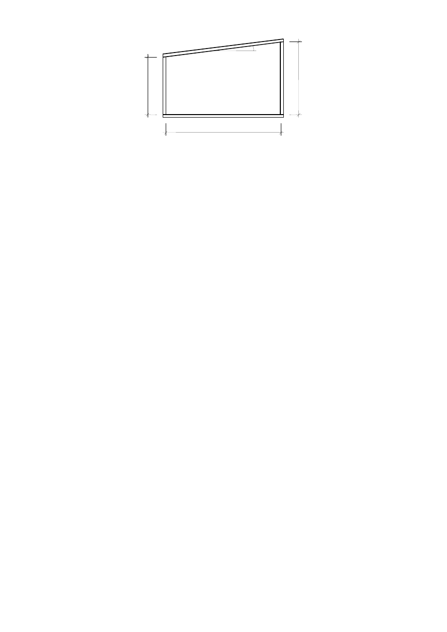
(2)
Provided adjacent spans do not differ more than 50% and any cantilever span is not larger than half the
adjacent span the effective lengths L
e
may be determined from Figure 3.1. For all other cases L
e
should be
taken as the distance between adjacent points of zero bending moment.
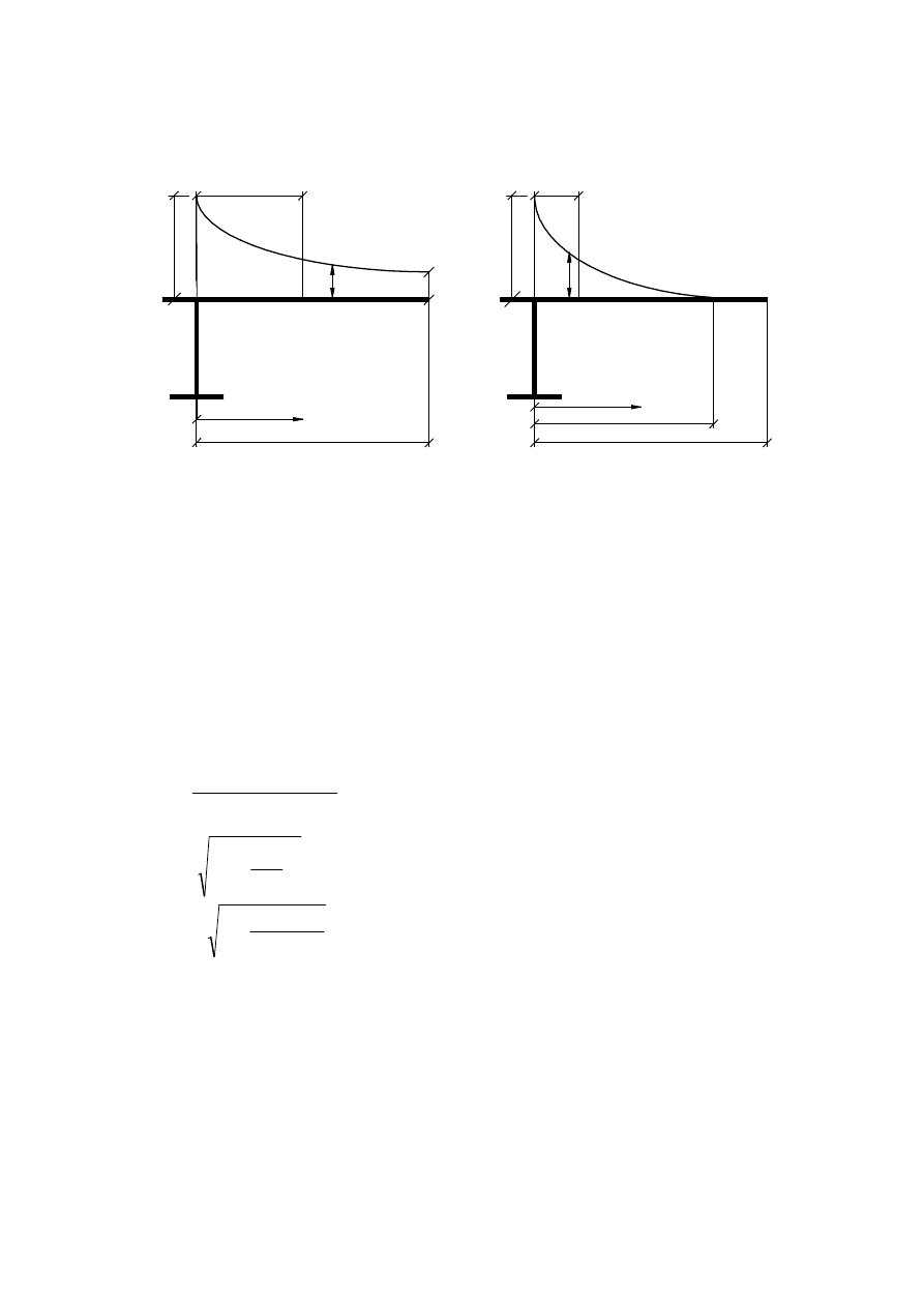
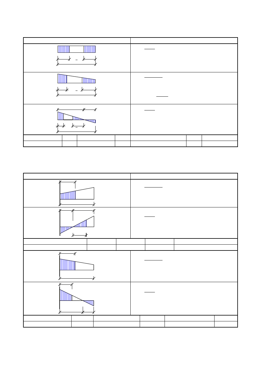
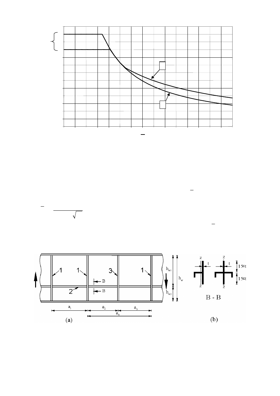
Figure 3.1: Effective length L
e
for continuous beam and distribution of
effective
s
width
L
L
L
L
/
4
L
/
2
L
/
4
L
/
4
L
/
2
L
/
4
L
=
0,
85
L
L
=
0
,
7
0L
L
=
0
,
2
5
(L
+
L
)
L
=
2
L
β
:
β
:
β
:
β
:
β
β
β
β
β
β
1
1
1
1
1
1
1
1
1
1
e
e
e
e
2
2
2
2
2
2
2
2
2
2
2
0
3
3
s
ˆ
‰
s
ˆ
‰
BS EN 1993-1-5:2006
EN 1993-1-5:2006 (E)
Licensed copy: BSI USER 06 Document Controller, Midmac Contracting Co. W.L.L, Version correct as of 26/05/2010
13:22, (c) BSI
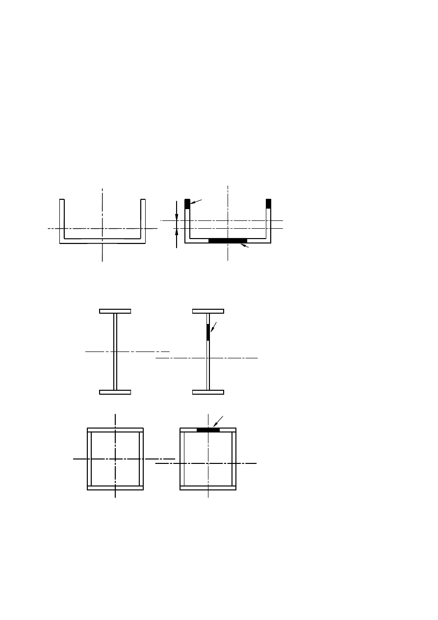
10
1 for flange outstand
2 for internal flange
3 plate thickness t
4 stiffeners with
∑
=
i
s
s
A
A
l
l
Figure 3.2: Notations for shear lag
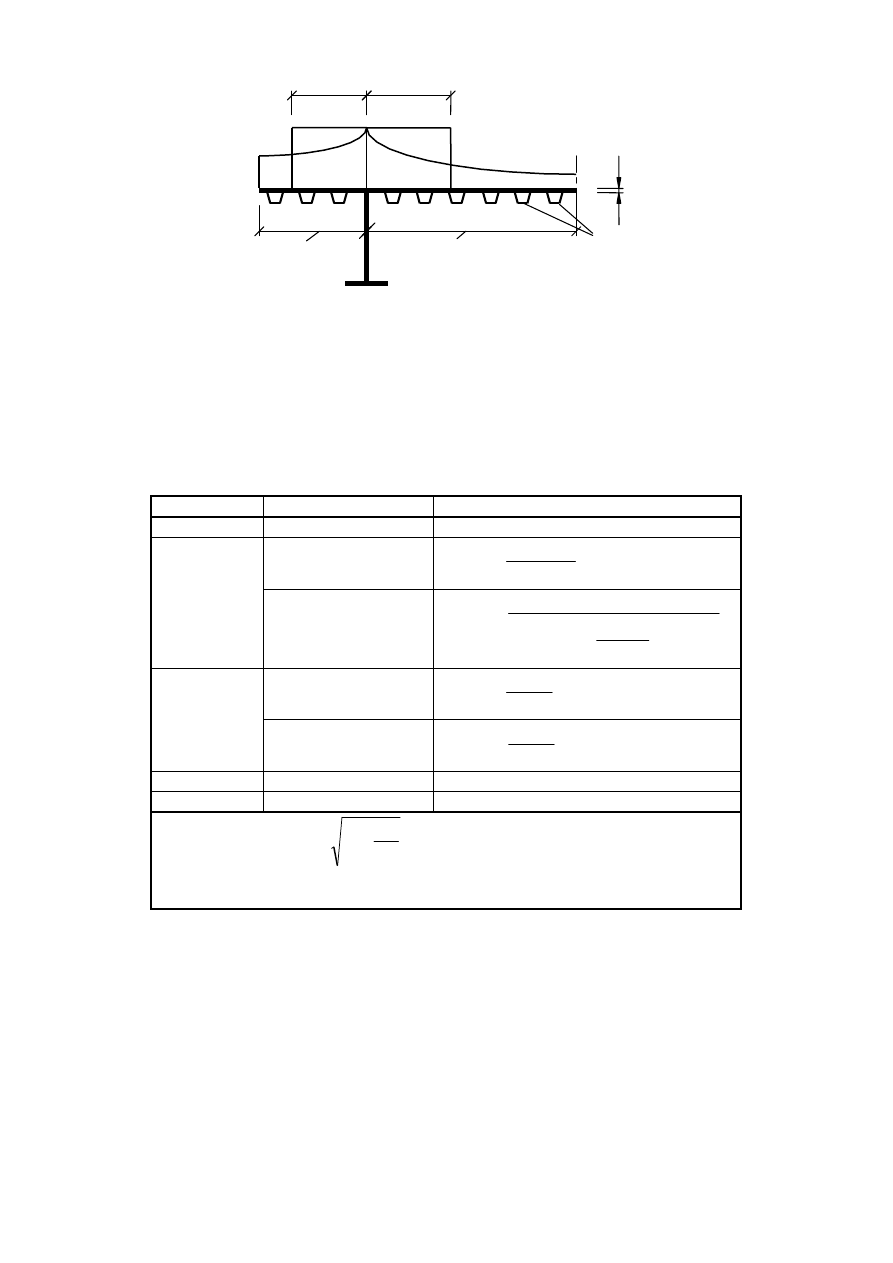
Table 3.1: Effective
s
width factor β
κ
Verification
β – value
κ ≤ 0,02
β = 1,0
sagging bending
2
1
4
,
6
1
1
κ
β
β
+
=
=
0,02 < κ ≤ 0,70
hogging bending
2
2
6
,
1
2500
1
0
,
6
1
1
κ
κ
κ
β
β
+
−
+
=
=
sagging bending
κ
β
β
9
,
5
1
1
=
=
> 0,70
hogging bending
κ
β
β
6
,
8
1
2
=
=
all κ
end support
β
0
= (0,55 + 0,025 / κ) β
1
, but β
0
< β
1
all κ
Cantilever
β = β
2
at support and at the end
κ = α
0
b
0
/ L
e
with
t
b
A
s
0
0
1
l
+
=
α
in which A
sℓ
is the area of all longitudinal stiffeners within the width b
0
and other
symbols are as defined in Figure 3.1 and Figure 3.2.
b
b
b
b
ef
f
e
ff
0
0
4
1
2
3
C
L
BS EN 1993-1-5:2006
EN 1993-1-5:2006 (E)
Licensed copy: BSI USER 06 Document Controller, Midmac Contracting Co. W.L.L, Version correct as of 26/05/2010
13:22, (c) BSI
11
3.2.2 Stress distribution due to shear lag
(1)
The distribution of longitudinal stresses across the flange plate due to shear lag should be obtained
from Figure 3.3.
b
b
y
y
b = b
σ
σ
σ
σ
σ
β
β
1
1
2
(y
)
(y
)
eff
eff
0
0
b = b
b = 5 b
0
0
1
0
β
(
)
( )
(
) (
)
4
0
2
1
2
1
2
/
1
20
,
0
25
,
1
:
20
,
0
b
y
y
−
−
+
=
−
=
>
σ
σ
σ
σ
σ
β
σ
β
( )
(
)
4
1
1
2
/
1
0
:
20
,
0
b
y
y
−
=
=
≤
σ
σ
σ
β
σ
1
is calculated
with the effective width
of the flange b
eff
Figure 3.3: Distribution of stresses due to shear lag
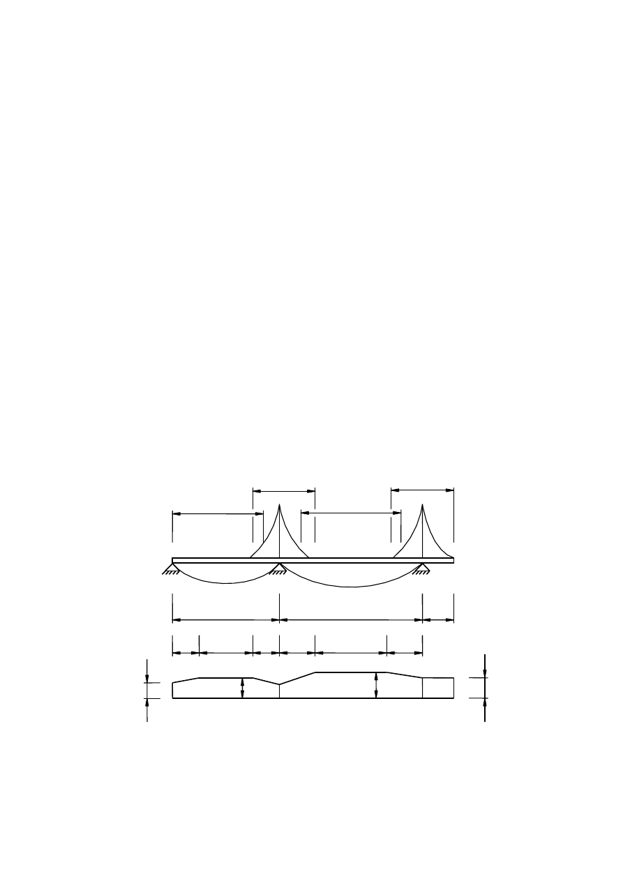
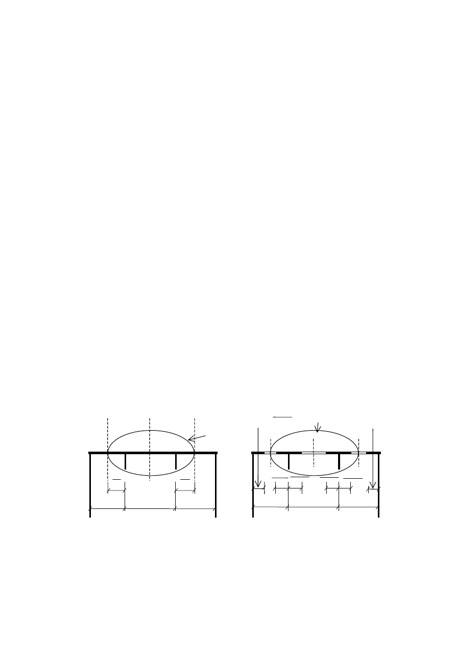
3.2.3 In-plane load effects
(1)
The elastic stress distribution in a stiffened or unstiffened plate due to the local introduction of in-
plane forces (patch loads), see Figure 3.4, should be determined from:
(
)
st
w
eff
Ed
Ed
z
a
t
b
F
,
,
+
=
σ
(3.2)
with:
2
1
+
=
n
s
z
s
b
e
e
eff
w
st
t
a
n
1
,
878
,
0
1
636
,
0
+
=
f
s
e
t
s
s
2
+
=
where a
st,1
is the gross cross-sectional
area of the
over the length s
e
.
This may be taken
t
w
is the web thickness;
z
is the distance to flange.
NOTE: The equation (3.2) is valid when s
st
/s
e
≤ 0,5; otherwise the contribution of stiffeners should be
neglected.
s
ˆ
‰
1
ˆ
‰
directly loade d
stiffeners divided
ˆ
‰
as the area of a sti
f fener smeared over the length of the spacing s
st
ˆ
‰
s
e
is the length of the stiff bearing;
s
st
is the spacing of stiffeners;
ˆ
‰
;
BS EN 1993-1-5:2006
EN 1993-1-5:2006 (E)
Licensed copy: BSI USER 06 Document Controller, Midmac Contracting Co. W.L.L, Version correct as of 26/05/2010
13:22, (c) BSI
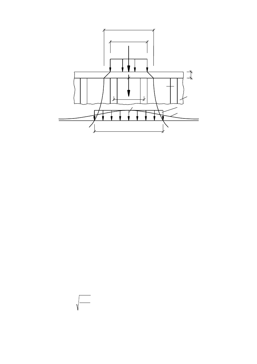
12
1 stiffener
2 simplified stress distribution
3 actual stress distribution
Figure 3.4: In-plane load introduction
NOTE: The above stress distribution may also be used for the fatigue verification.
3.3 Shear lag at the ultimate limit state
(1)
At the ultimate limit state shear lag effects may be determined as follows:
a) elastic shear lag effects as determined for serviceability and fatigue limit states,
b) combined effects of shear lag and of plate buckling,
c) elastic-plastic shear lag effects allowing for limited plastic strains.
NOTE 1: The National Annex may choose the method to be applied. Unless specified otherwise in EN 1993-2
to EN 1993-6, the method in NOTE 3 is recommended.
NOTE 2: The combined effects of plate buckling and shear lag may be taken into account by using A
eff
as given
by:
ult
eff
c
eff
A
A
β
,
=
(3.3)
where A
c,eff
is the effective
p
area of the compression flange due to plate buckling (see 4.4 and 4.5);
β
ult
is the effective
s
width factor for the effect of shear lag at the ultimate limit state, which may be
taken as
β determined from Table 3.1 with
α
0
replaced by
f
eff
c
t
b
A
0
,
*
0
=
α
(3.4)
t
f
is the flange thickness.
b
s
s
σ
z
F
1 :1
t
t
z
,
E
d
z
,
E
d
f
w
ef
f
s
t
ef
f
s
e
1
s
2
3
BS EN 1993-1-5:2006
EN 1993-1-5:2006 (E)
Licensed copy: BSI USER 06 Document Controller, Midmac Contracting Co. W.L.L, Version correct as of 26/05/2010
13:22, (c) BSI

13
NOTE 3: Elastic-plastic shear lag effects allowing for limited plastic strains may be taken into account using
A
eff
as follows:
β
β
κ
eff
c
eff
c
eff
A
A
A
,
,
≥
=
(3.5)
where
β
and
κ
are taken from Table 3.1.
The expressions in NOTE 2 and NOTE 3 may also be applied for flanges in tension in which case A
c,eff
should be
replaced by the gross area of the tension flange.
4 Plate buckling effects due to direct stresses at the ultimate limit state
4.1 General
(1)
This section gives rules to account for plate buckling effects from direct stresses at the ultimate limit
state when the following criteria are met:
a) The panels are rectangular and flanges are parallel or nearly parallel (see 2.3);
b) Stiffeners, if any, are provided in the longitudinal or transverse direction or both;
c) Open holes and cut outs are small (see 2.3);
d) Members are of uniform cross section;
e) No flange induced web buckling occurs.
NOTE 1: For compression flange buckling in the plane of the web see section 8.
NOTE 2: For stiffeners and detailing of plated members subject to plate buckling see section 9.
4.2 Resistance to direct stresses
(1) The resistance of plated members may be determined
using the effective areas
of plate elements
in
compression for class 4 sections using cross sectional data (A
eff
, I
eff
, W
eff
) for cross sectional verifications
and member verifications for column buckling and lateral torsional buckling according to EN 1993-1-1.
(2)
Effective
p
areas should be determined on the basis of the linear strain distributions with the attainment
of yield strain in the mid plane of the compression plate.
4.3 Effective cross section
(1)
In calculating longitudinal stresses, account should be taken of the combined effect of shear lag and
plate buckling using the effective areas given in 3.3.
(2)
The effective cross sectional properties of members should be based on the effective areas of the
compression elements and on the effective
s
area of the tension elements due to shear lag.
(3)
The effective area A
eff
should be determined assuming that the cross section is subject only to stresses
due to uniform axial compression. For non-symmetrical cross sections the possible shift e
N
of the centroid of
the effective area A
eff
relative to the centre of gravity of the gross cross-section, see Figure 4.1, gives an
additional moment which should be taken into account in the cross section verification using 4.6.
(4)
The effective section modulus W
eff
should be determined assuming the cross section is subject only to
bending stresses, see Figure 4.2. For biaxial bending effective section moduli should be determined about
both main axes.
NOTE: As an alternative to 4.3(3) and (4) a single effective section may be determined from N
Ed
and M
Ed
acting
simultaneously. The effects of e
N
should be taken into account as in 4.3(3). This requires an iterative procedure.
p
ˆ
‰
BS EN 1993-1-5:2006
EN 1993-1-5:2006 (E)
Licensed copy: BSI USER 06 Document Controller, Midmac Contracting Co. W.L.L, Version correct as of 26/05/2010
13:22, (c) BSI
14
(5)
The stress in a flange should be calculated using the elastic section modulus with reference to the mid-
plane of the flange.
(6)
Hybrid girders may have flange material with yield strength f
yf
up to
φ
h
×f
yw
provided that:
a) the increase of flange stresses caused by yielding of the web is taken into account by limiting the stresses
in the web to f
yw
;
b) f
yf
is used in determining the effective area of the web.
NOTE: The National Annex may specify the value
φ
h
. A value of
φ
h
= 2,0 is recommended.
(7)
The increase of deformations and of stresses at serviceability and fatigue limit states may be ignored
for hybrid girders complying with 4.3(6) including the NOTE.
(8)
For hybrid girders complying with 4.3(6) the stress range limit in EN 1993-1-9 may be taken as 1,5f
yf
.
Gross cross section
Effective cross section
G centroid of the gross cross
section
G´ centroid of the effective
cross section
1 centroidal axis of the gross
cross section
2 centroidal axis of the
effective cross section
3 non effective zone
Figure 4.1: Class 4 cross-sections - axial force
G
G´
G´
G
1
1
2
2
3
3
Gross cross section
Effective cross section
G centroid of the gross cross
section
G´ centroid of the effective
cross section
1 centroidal axis of the gross
cross section
2 centroidal axis of the
effective cross section
3 non effective zone
Figure 4.2: Class 4 cross-sections - bending moment
G
1
2
3
3
G
G´
e
N
text deleted
ˆ
‰
BS EN 1993-1-5:2006
EN 1993-1-5:2006 (E)
Licensed copy: BSI USER 06 Document Controller, Midmac Contracting Co. W.L.L, Version correct as of 26/05/2010
13:22, (c) BSI

15
4.4 Plate elements without longitudinal stiffeners
(1)
The effective
p
areas of flat compression elements should be obtained using Table 4.1 for internal
elements and Table 4.2 for outstand elements. The effective
p
area of the compression zone of a plate with the
gross cross-sectional area A
c
should be obtained from:
A
c,eff
= ρ A
c
(4.1)
where ρ is the reduction factor for plate buckling.
(2)
The reduction factor ρ may be taken as follows:
–
internal compression elements:
ρ
= 1,0
for
(
)
0
,
1
3
055
,
0
2
≤
+
−
=
p
p
λ
ψ
λ
ρ
for
,
(4.2)
–
outstand compression elements:
ρ
= 1,0
for
748
,
0
≤
p
λ
0
,
1
188
,
0
2
≤
−
=
p
p
λ
λ
ρ
for
748
,
0
>
p
λ
(4.3)
where
σ
ε
σ
λ
k
t
b
f
cr
y
p
4
,
28
/
=
=
ψ
is the stress ratio determined in accordance with 4.4(3) and 4.4(4)
b
is the appropriate width to be taken as follows (for definitions, see Table 5.2 of EN 1993-1-1)
b
w
for webs;
b
for internal flange elements (except RHS);
b
- 3 t for flanges of RHS;
c
for outstand flanges;
h
for equal-leg angles;
h
for unequal-leg angles;
k
σ
is the buckling factor corresponding to the stress ratio ψ and boundary conditions. For long plates k
σ
is
given in Table 4.1 or Table 4.2 as appropriate;
t
is the thickness;
σ
cr
is the elastic critical plate buckling stress see equation (A.1) in Annex A.1(2) and Table 4.1 and Table
4.2;
[
]
2
/
235
mm
N
f
y
=
ε
(3)
For flange elements of I-sections and box girders the stress ratio
ψ
used in Table 4.1 and Table 4.2
should be based on the properties of the gross cross-sectional area, due allowance being made for shear lag in
the flanges if relevant. For web elements the stress ratio ψ used in Table 4.1 should be obtained using a stress
distribution based on the effective area of the compression flange and the gross area of the web.
NOTE: If the stress distribution results from different stages of construction (as e.g. in a composite bridge) the
stresses from the various stages may first be calculated with a cross section consisting of effective flanges and
‰
‰
ψ
−
+
≤
λ
055
0
085
0
5
0
.
.
,
p
ψ
−
+
>
λ
055
0
085
0
5
0
.
.
,
p
ˆ
ˆ
text deleted
ˆ
‰
BS EN 1993-1-5:2006
EN 1993-1-5:2006 (E)
Licensed copy: BSI USER 06 Document Controller, Midmac Contracting Co. W.L.L, Version correct as of 26/05/2010
13:22, (c) BSI
16
gross web and these stresses are added together. This resulting stress distribution determines an effective web
section that can be used for all stages to calculate the final stress distribution for stress analysis.
(4)
Except as given in 4.4(5), the plate slenderness
p
λ
of an element may be replaced by:
0
,
,
/
M
y
Ed
com
p
red
p
f
γ
σ
λ
λ
=
(4.4)
where σ
com,Ed
is the maximum design compressive stress in the element determined using the effective
p
area of the section caused by all simultaneous actions.
NOTE 1: The above procedure is conservative and requires an iterative calculation in which the stress ratio ψ
(see Table 4.1 and Table 4.2) is determined at each step from the stresses calculated on the effective
p
cross-
section defined at the end of the previous step.
NOTE 2: See also alternative procedure in Annex E.
(5)
For the verification of the design buckling resistance of a class 4 member using 6.3.1, 6.3.2 or 6.3.4 of
EN 1993-1-1, either the plate slenderness
p
λ
or
red
p
,
λ
with σ
com,Ed
based on second order analysis with
global imperfections should be used.
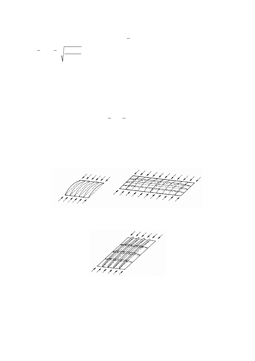
(6)
For aspect ratios a/b < 1 a column type of buckling may occur and the check should be performed
according to 4.5.4 using the reduction factor
ρ
c
.
NOTE: This applies e.g. for flat elements between transverse stiffeners where plate buckling could be column-
like and require a reduction factor
ρ
c
close to
χ
c
as for column buckling, see Figure 4.3 a) and b). For plates with
longitudinal stiffeners column type buckling may also occur for a/b
≥ 1, see Figure 4.3 c).
a) column-like behaviour
of plates without
longitudinal supports
b) column-like behaviour of an
unstiffened plate with a small
aspect ratio
α
c) column-like behaviour of a longitudinally
stiffened plate with a large aspect ratio
α
Figure 4.3: Column-like behaviour
BS EN 1993-1-5:2006
EN 1993-1-5:2006 (E)
Licensed copy: BSI USER 06 Document Controller, Midmac Contracting Co. W.L.L, Version correct as of 26/05/2010
13:22, (c) BSI
17
Table 4.1: Internal compression elements
Stress distribution (compression positive)
Effective
p
width b
eff
ψ = 1:
b
eff
= ρ
b
b
e1
= 0,5 b
eff
b
e2
= 0,5 b
eff
1 > ψ ≥ 0:
b
eff
= ρ
b
eff
e
b
b
ψ
−
=
5
2
1
b
e2
= b
eff
- b
e1
ψ < 0:
b
eff
= ρ b
c
= ρ
b
/ (1-ψ)
b
e1
= 0,4 b
eff
b
e2
= 0,6 b
eff
ψ = σ
2
/σ
1
1
1 > ψ > 0
0
0 > ψ > -1
-1
Buckling factor k
σ
4,0
8,2 / (1,05 + ψ)
7,81
7,81 - 6,29ψ + 9,78ψ
2
23,9
5,98 (1 - ψ)
2
Table 4.2: Outstand compression elements
Stress distribution (compression positive)
Effective
p
width b
eff
1 > ψ ≥ 0:
b
eff
= ρ c
ψ < 0:
b
eff
= ρ b
c
= ρ c / (1-ψ)
ψ = σ
2
/
σ
1
1
0
-1
1 ≥ ψ ≥ -3
Buckling factor k
σ
0,43
0,57
0,85
0,57 - 0,21ψ + 0,07ψ
2
1 > ψ ≥ 0:
b
eff
= ρ c
ψ < 0:
b
eff
= ρ b
c
= ρ c / (1-ψ)
ψ = σ
2
/σ
1
1
1 > ψ > 0
0
0 > ψ > -1
-1
Buckling factor k
σ
0,43
0,578 / (ψ + 0,34)
1,70
1,7 - 5ψ + 17,1ψ
2
23,8
b
σ
σ
1
2
b
b
e2
e1
b
σ
σ
1
2
b
b
e2
e
1
b
σ
σ
1
2
b
b
b
b
e2
t
e
1
c
σ
σ
2
1
b
c
ef
f
σ
σ
2
1
b
b
b
ef
f
t
c
σ
σ
1
2
b
c
e
f
f
σ
σ
1
2
b
c
b
b
e
f
f
t
-1 > ψ
≥
-3
ˆ
‰
BS EN 1993-1-5:2006
EN 1993-1-5:2006 (E)
Licensed copy: BSI USER 06 Document Controller, Midmac Contracting Co. W.L.L, Version correct as of 26/05/2010
13:22, (c) BSI
18
4.5 Stiffened plate elements with longitudinal stiffeners
4.5.1 General
(1)
For plates with longitudinal stiffeners the effective
p
areas from local buckling of the various subpanels
between the stiffeners and the effective
p
areas from the global buckling of the stiffened panel should be
accounted for.
(2)
The effective
p
section area of each subpanel should be determined by a reduction factor in accordance
with 4.4 to account for local plate buckling. The stiffened plate with effective
p
section areas for the stiffeners
should be checked for global plate buckling (by modelling it as an equivalent orthotropic plate) and a
reduction factor
should be determined for overall plate buckling.
(3)
The effective
p
area of the compression zone of the stiffened plate should be taken as:
∑
+
=
t
b
A
A
eff
edge
loc
eff
c
c
eff
c
,
,
,
,
ρ
(4.5)
where A
c,eff,loc
is the effective
p
section area
of all the stiffeners and subpanels that are fully or partially
in the compression zone except the effective parts supported by an adjacent plate element with the width
b
edge,eff
,
see example in Figure 4.4.
(4)
The area A
c,eff,loc
should be obtained from:
t
b
A
A
loc
c
c
loc
eff
s
loc
eff
c
,
,
,
,
∑
+
=
ρ
l
(4.6)
where
∑
c
applies to the part of the stiffened panel width that is in compression except the parts b
edge,eff
,
see Figure 4.4;
A
sℓ,eff
is the sum of the effective
p
sections according to 4.4 of all longitudinal stiffeners with gross
area A
sℓ
located in the compression zone;
b
c,loc
is the width of the compressed part of each subpanel;
ρ
loc
is the reduction factor from 4.4(2) for each subpanel.
Figure 4.4: Stiffened plate under uniform compression
NOTE: For non-uniform compression see Figure A.1.
A
c
b
1
b
2
b
3
2
1
b
2
b
3
b
1
b
2
b
3
2
1
1
ρ
b
2
3
3
ρ
b
A
c,eff,loc
2
2
2
ρ
b
2
1
1
,
,
1
ρ
b
b
eff
edge
=
eff
edge
b
,
,
3
2
2
2
ρ
b
c
ρ
ˆ ‰
ˆ
‰
BS EN 1993-1-5:2006
EN 1993-1-5:2006 (E)
Licensed copy: BSI USER 06 Document Controller, Midmac Contracting Co. W.L.L, Version correct as of 26/05/2010
13:22, (c) BSI

19
(5)
In determining the reduction factor ρ
c
for overall buckling, the reduction factor for column-type
buckling, which is more severe than the reduction factor than for plate buckling, should be considered.
(6)
Interpolation should be carried out in accordance with 4.5.4(1) between the reduction factor ρ for plate
buckling and the reduction factor χ
c
for column buckling to determine
ρ
c
see 4.5.4.
(7)
The reduction of the compressed area A
c,eff,loc
through ρ
c
may be taken as a uniform reduction across
the whole cross section.
(8)
If shear lag is relevant (see 3.3), the effective cross-sectional area A
c,eff
of the compression zone of the
stiffened plate should then be taken as
*
,eff
c
A
accounting not only for local plate buckling effects but also for
shear lag effects.
(9)
The effective cross-sectional area of the tension zone of the stiffened plate should be taken as the gross
area of the tension zone reduced for shear lag if relevant, see 3.3.
(10) The effective section modulus W
eff
should be taken as the second moment of area of the effective cross
section divided by the distance from its centroid to the mid depth of the flange plate.
4.5.2 Plate type behaviour
(1)
The relative plate slenderness
p
λ
of the equivalent plate is defined as:
p
cr
y
c
A
p
f
,
,
σ
β
λ
=
(4.7)
with
c
loc
eff
c
c
A
A
A
,
,
,
=
β
where A
c
is the gross area of the compression zone of the stiffened plate except the parts of subpanels
supported by an adjacent plate, see Figure 4.4 (to be multiplied by the shear lag factor if
shear lag is relevant, see 3.3);
A
c,eff,loc
is the effective area of the same part of the plate (including shear lag effect, if relevant) with
due allowance made for possible plate buckling of subpanels and/or stiffeners.
(2)
The reduction factor ρ for the equivalent orthotropic plate is obtained from 4.4(2) provided
p
λ
is
calculated from equation (4.7).
NOTE: For calculation of
σ
cr,p
see Annex A.
4.5.3 Column type buckling behaviour
(1)
The elastic critical column buckling stress σ
cr,c
of an unstiffened (see 4.4) or stiffened (see 4.5) plate
should be taken as the buckling stress with the supports along the longitudinal edges removed.
(2)
For an unstiffened plate the elastic critical column buckling stress
σ
cr,c
may be obtained from
(
)
2
2
2
2
,
1
12
a
t
E
c
cr
ν
π
σ
−
=
(4.8)
(3)
For a stiffened plate
σ
cr,c
may be determined from the elastic critical column buckling stress
σ
cr,sl
of the
stiffener closest to the panel edge with the highest compressive stress as follows:
2
1
,
1
,
2
,
a
A
I
E
s
s
s
cr
l
l
l
π
σ
=
(4.9)
BS EN 1993-1-5:2006
EN 1993-1-5:2006 (E)
Licensed copy: BSI USER 06 Document Controller, Midmac Contracting Co. W.L.L, Version correct as of 26/05/2010
13:22, (c) BSI

20
where
1
,
l
s
I
is the second moment of area of the gross cross section of the stiffener and the adjacent parts
of the plate, relative to the out-of-plane bending of the plate;
1
,
l
s
A
is the gross cross-sectional area of the stiffener and the adjacent parts of the plate according to
Figure A.1.
NOTE: σ
cr,c
may be obtained from
1
,
,
,
l
l
s
c
s
cr
c
cr
b
b
σ
σ
=
, where
σ
cr,c
is related to the compressed edge of the
plate, and ,
and b
c
are geometric values from the stress distribution used for the extrapolation, see
Figure A.1.
(4)
The relative column slenderness
c
λ
is defined as follows:
c
cr
y
c
f
,
σ
λ
=
for unstiffened plates
(4.10)
c
cr
y
c
A
c
f
,
,
σ
β
λ
=
for stiffened plates
(4.11)
with
1
,
,
1
,
,
l
l
s
eff
s
c
A
A
A
=
β
;
1
,
l
s
A
is defined in 4.5.3(3);
eff
s
A
,
1
,
l
is the effective cross-sectional area of the stiffener and the adjacent parts of the plate with
due allowance for plate buckling, see Figure A.1.
(5)
The reduction factor χ
c
should be obtained from 6.3.1.2 of EN 1993-1-1. For unstiffened plates
α = 0,21 corresponding to buckling curve a should be used. For stiffened plates its value should be increased
to:
e
i
e
/
09
,
0
+
=
α
α
(4.12)
with
1
,
1
,
l
l
s
s
A
I
i
=
e
= max (e
1
, e
2
) is the largest distance from the respective centroids of the plating and the one-sided
stiffener (or of the centroids of either set of stiffeners when present on both sides) to the neutral
axis of the effective column, see Figure A.1;
α = 0,34 (curve b) for closed section stiffeners;
= 0,49 (curve c) for open section stiffeners.
4.5.4 Interaction between plate and column buckling
(1)
The final reduction factor ρ
c
should be obtained by interpolation between χ
c
and ρ as follows:
(
) (
)
c
c
c
χ
ξ
ξ
χ
ρ
ρ
+
−
−
=
2
(4.13)
where
1
,
,
−
=
c
cr
p
cr
σ
σ
ξ
but
1
0
≤
≤
ξ
σ
cr,p
is the elastic critical plate buckling stress, see Annex A.1(2);
σ
cr,c
is the elastic critical column buckling stress according to 4.5.3(2) and (3), respectively;
1
,
l
s
b
ˆ
‰
BS EN 1993-1-5:2006
EN 1993-1-5:2006 (E)
Licensed copy: BSI USER 06 Document Controller, Midmac Contracting Co. W.L.L, Version correct as of 26/05/2010
13:22, (c) BSI

21
χ
c
is the reduction factor due to column buckling.
ρ
is the reduction factor due to plate buckling, see 4.4(1).
4.6 Verification
(1)
Member verification
should be performed as follows:
0
,
1
0
0
1
≤
+
+
=
M
eff
y
N
Ed
Ed
M
eff
y
Ed
W
f
e
N
M
A
f
N
γ
γ
η
(4.14)
where A
eff
is the effective cross-section area in accordance with 4.3(3);
e
N
is the shift in the position of neutral axis, see 4.3(3);
M
Ed
is the design bending moment;
N
Ed
is the design axial force;
W
eff
is the effective elastic section modulus, see 4.3(4);
γ
M0
is the partial factor, see application parts EN 1993-2 to 6.
NOTE: For members subject to compression and biaxial bending the above equation (4.14) may be modified as
follows:
0
,
1
0
,
,
,
0
,
,
,
0
1
≤
+
+
+
+
=
M
eff
z
y
N
z
Ed
Ed
z
M
eff
y
y
N
y
Ed
Ed
y
M
eff
y
Ed
W
f
e
N
M
W
f
e
N
M
A
f
N
γ
γ
γ
η
(4.15)
M
y,Ed
, M
z,Ed
are the design bending moments with respect to y–y and z–z axes respectively;
e
y,N
, e
z,N
are the eccentricities with respect to the neutral axis.
(2)
Action effects M
Ed
and N
Ed
should include global second order effects where relevant.
(3)
The plate buckling verification of the panel should be carried out for the stress resultants at a distance
0,4a or 0,5b, whichever is the smallest, from the panel end where the stresses are the greater. In this case the
gross sectional resistance needs to be checked at the end of the panel.
5 Resistance to shear
5.1 Basis
(1)
This section gives rules for shear resistance of plates considering shear buckling at the ultimate limit
state where the following criteria are met:
a) the panels are rectangular within the angle limit stated in 2.3;
b) stiffeners, if any, are provided in the longitudinal or transverse direction or both;
c) all holes and cut outs are small (see 2.3);
d) members are of uniform cross section.
(2)
Plates with h
w
/t greater than
ε
η
72
for an unstiffened web, or
τ
ε
η
k
31
for a stiffened web, should be
checked for resistance to shear buckling and should be provided with transverse stiffeners at the supports,
where
[
]
2
/
235
mm
N
f
y
=
ε
.
for compression and uniaxial bending
ˆ
‰
ˆ
‰
BS EN 1993-1-5:2006
EN 1993-1-5:2006 (E)
Licensed copy: BSI USER 06 Document Controller, Midmac Contracting Co. W.L.L, Version correct as of 26/05/2010
13:22, (c) BSI
22
NOTE 1: h
w
see Figure 5.1 and for k
τ
see 5.3(3).
NOTE 2: The National Annex will define
η
. The value
η
= 1,20 is recommended for steel grades up to and
including S460. For higher steel grades
η
= 1,00 is recommended.
5.2 Design resistance
(1)
For unstiffened or stiffened webs the design resistance for shear should be taken as:
1
,
,
,
3
M
w
yw
Rd
bf
Rd
bw
Rd
b
t
h
f
V
V
V
γ
η
≤
+
=
(5.1)
in which the contribution from the web is given by:
1
,
3
M
w
yw
w
Rd
bw
t
h
f
V
γ
χ
=
(5.2)
and the contribution from the flanges V
bf,Rd
is according to 5.4.
(2)
Stiffeners should comply with the requirements in 9.3 and welds should fulfil the requirement given in
9.3.5.
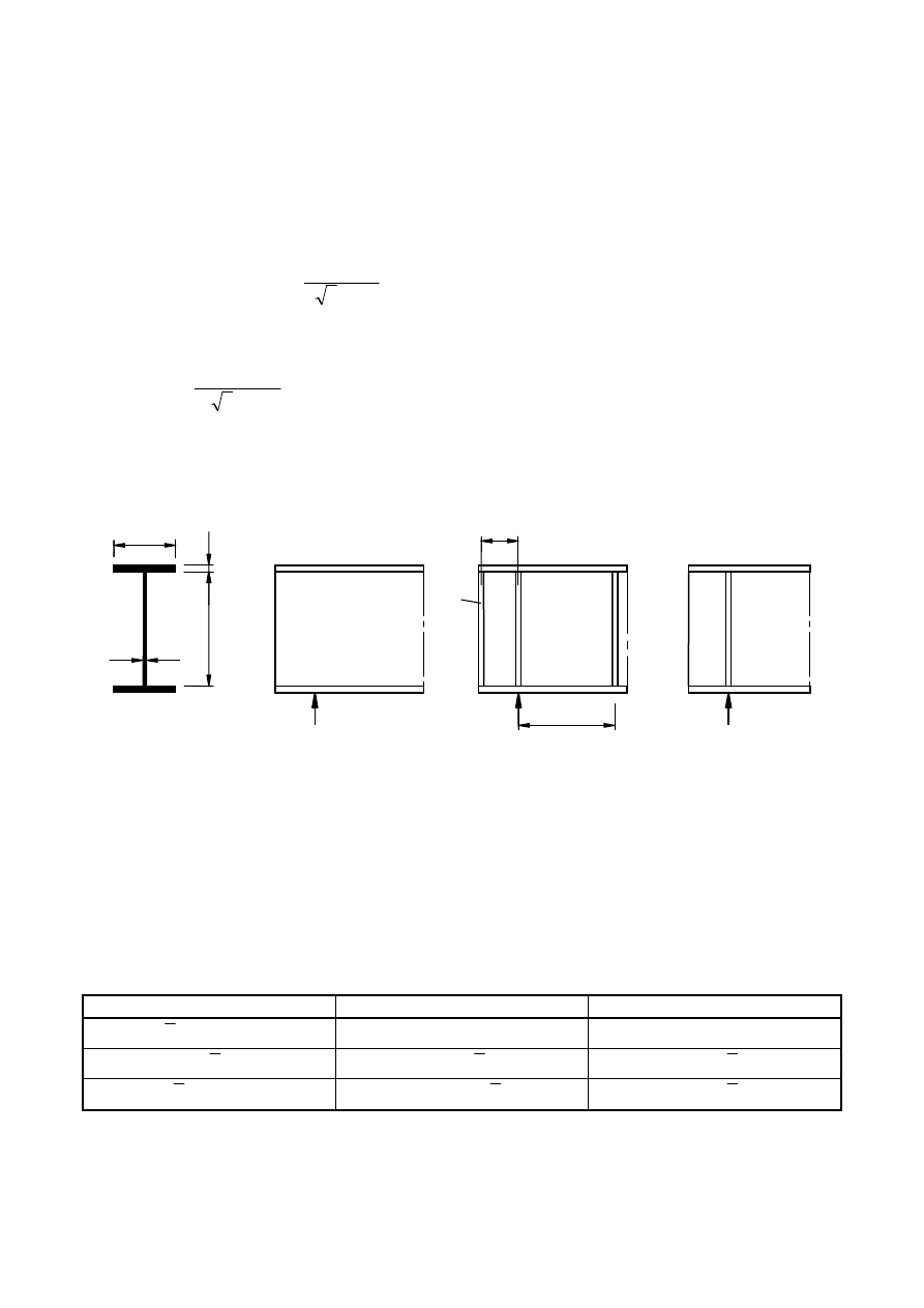
Cross section notations
a) No end post
b) Rigid end post
c) Non-rigid end post
Figure 5.1: End supports
5.3 Contribution from the web
(1)
For webs with transverse stiffeners at supports only and for webs with either intermediate transverse
stiffeners or longitudinal stiffeners or both, the factor
χ
w
for the contribution of the web to the shear buckling
resistance should be obtained from Table 5.1 or Figure 5.2.
Table 5.1: Contribution from the web χ
w
to shear buckling resistance
Rigid end post
Non-rigid end post
η
λ
/
83
,
0
<
w
η
η
08
,
1
/
83
,
0
<
≤
w
λ
η
w
λ
/
83
,
0
w
λ
/
83
,
0
08
,
1
≥
w
λ
(
)
w
λ
+
7
,
0
/
37
,
1
w
λ
/
83
,
0
NOTE: See 6.2.6 in EN 1993-1-1.
b
h
w
t
t
f
f
a
e
A
e
BS EN 1993-1-5:2006
EN 1993-1-5:2006 (E)
Licensed copy: BSI USER 06 Document Controller, Midmac Contracting Co. W.L.L, Version correct as of 26/05/2010
13:22, (c) BSI
23
(2)
Figure 5.1 shows various end supports for girders:
a)
No end post, see 6.1 (2), type c);
b) Rigid end posts, see 9.3.1; this case is also applicable for panels at an intermediate support of a
continuous girder;
c)
Non rigid end posts see 9.3.2.
(3)
The
w
λ
in Table 5.1 and Figure 5.2 should be taken as:
cr
yw
w
f
τ
λ
76
,
0
=
(5.3)
where
E
cr
k
σ
τ
τ
=
(5.4)
NOTE 1: Values for σ
E
and k
τ
may be taken from Annex A.
NOTE 2: The
w
λ
may be taken as follows:
a) transverse stiffeners at supports only:
ε
λ
t
h
w
w
4
,
86
=
(5.5)
b) transverse stiffeners at supports and intermediate transverse or longitudinal stiffeners or both:
τ
ε
λ
k
t
h
w
w
4
,
37
=
(5.6)
in which k
τ
is the minimum shear buckling coefficient for the web panel.
NOTE 3: Where non-rigid transverse stiffeners are also used in addition to rigid transverse stiffeners, k
τ
is taken
as the minimum of the values from the web panels between any two transverse stiffeners (e.g. a
2
× h
w
and a
3
×
h
w
) and that between two rigid stiffeners containing non-rigid transverse stiffeners (e.g. a
4
× h
w
).
NOTE 4: Rigid boundaries may be assumed for panels bordered by flanges and rigid transverse stiffeners. The
web buckling analysis can then be based on the panels between two adjacent transverse stiffeners (e.g. a
1
× h
w
in
Figure 5.3).
NOTE 5: For non-rigid transverse stiffeners the minimum value k
τ
may be obtained from the buckling analysis
of the following:
1. a combination of two adjacent web panels with one flexible transverse stiffener
2. a combination of three adjacent web panels with two flexible transverse stiffeners
For procedure to determine k
τ
see Annex A.3.
(4)
The second moment of area of a longitudinal stiffener should be reduced to 1/3 of its actual value
when calculating k
τ
. Formulae for k
τ
taking this reduction into account in A.3 may be used.
modified slenderness
ˆ
‰
modified slenderness
ˆ
‰
BS EN 1993-1-5:2006
EN 1993-1-5:2006 (E)
Licensed copy: BSI USER 06 Document Controller, Midmac Contracting Co. W.L.L, Version correct as of 26/05/2010
13:22, (c) BSI
24
1 Rigid end post
2 Non-rigid end post
3 Range of recommended
η
Figure 5.2: Shear buckling factor χ
w
(5)
For webs with longitudinal stiffeners the
w
λ
in (3) should not be taken
as less than
i
wi
w
k
t
h
τ
ε
λ
4
,
37
=
(5.7)
where h
wi
and k
τi
refer to the subpanel with the largest
w
λ
of all subpanels
within the web panel under consideration.
NOTE: To calculate k
τ
i
the expression given in A.3 may be used with k
τ
st
= 0.
1 Rigid transverse stiffener
2 Longitudinal stiffener
3 Non-rigid transverse stiffener
0
0,1
0,2
0,3
0,4
0,5
0,6
0,7
0,8
0,9
1
1,1
1,2
1,3
0
0,2
0,4
0,6
0,8
1
1,2
1,4
1,6
1,8
2
2,2
2,4
2,6
2,8
3
8
8
8
8
w
P
P
P
P
w
1
2
3
modified slenderness
ˆ
‰
modified slenderness
ˆ
‰
BS EN 1993-1-5:2006
EN 1993-1-5:2006 (E)
Licensed copy: BSI USER 06 Document Controller, Midmac Contracting Co. W.L.L, Version correct as of 26/05/2010
13:22, (c) BSI

25
Figure 5.3: Web with transverse and longitudinal stiffeners
5.4 Contribution from flanges
(1)
When the flange resistance is not completely utilized in resisting the bending moment (M
Ed
< M
f,Rd
)
the contribution from the flanges should be obtained as follows:
−
=
2
,
1
2
,
1
Rd
f
Ed
M
yf
f
f
Rd
bf
M
M
c
f
t
b
V
γ
(5.8)
b
f
and t
f
are taken for the flange which provides the least axial resistance,
b
f
being taken as not larger than 15εt
f
on each side of the web,
0
,
,
M
k
f
Rd
f
M
M
γ
=
is the moment of resistance of the cross section consisting of the effective area of the
flanges only,
+
=
yw
w
yf
f
f
f
h
t
f
t
b
a
c
2
2
6
,
1
25
,
0
(2)
When an axial force N
Ed
is present, the value of M
f,Rd
should be reduced by multiplying it by the
following factor:
(
)
+
−
0
2
1
1
M
yf
f
f
Ed
f
A
A
N
γ
(5.9)
where A
f1
and A
f2
are the areas of the top and bottom flanges respectively.
5.5 Verification
(1)
The verification should be performed as follows:
0
,
1
,
3
≤
=
Rd
b
Ed
V
V
η
(5.10)
where V
Ed
is the design shear force including shear from torque.
6 Resistance to transverse forces
6.1 Basis
(1)
The design resistance of the webs of rolled beams and welded girders should be determined in
accordance with 6.2, provided that the compression flange is adequately restrained in the lateral direction.
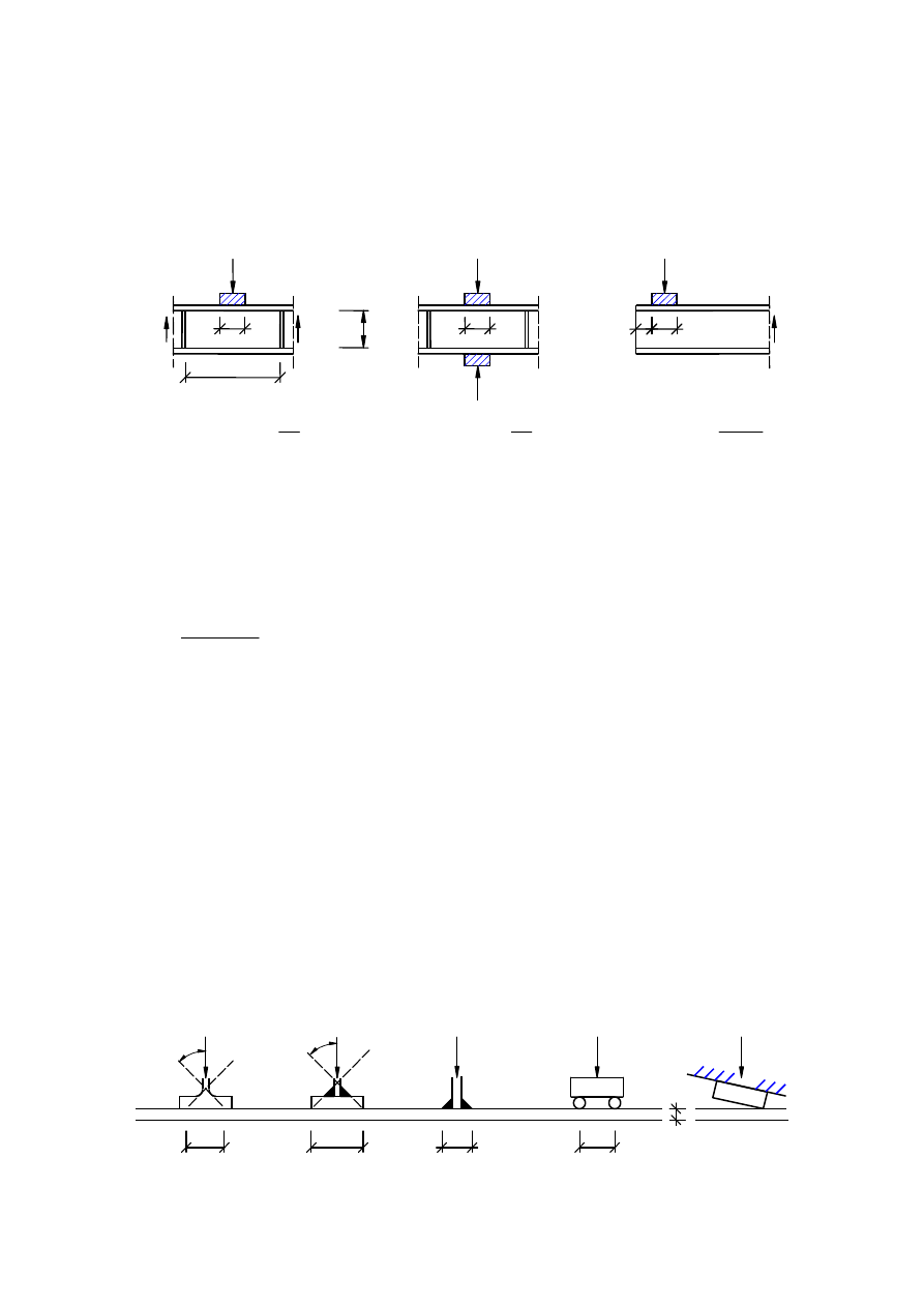
(2)
The load is applied as follows:
a) through the flange and resisted by shear forces in the web, see Figure 6.1 (a);
b) through one flange and transferred through the web directly to the other flange, see Figure 6.1 (b).
c) through one flange adjacent to an unstiffened end, see Figure 6.1 (c)
BS EN 1993-1-5:2006
EN 1993-1-5:2006 (E)
Licensed copy: BSI USER 06 Document Controller, Midmac Contracting Co. W.L.L, Version correct as of 26/05/2010
13:22, (c) BSI
26
(3)
For box girders with inclined webs the resistance of both the web and flange should be checked. The
internal forces to be taken into account are the components of the external load in the plane of the web and
flange respectively.
(4)
The interaction of the transverse force, bending moment and axial force should be verified using 7.2.
Type (a)
Type (b)
Type (c)
2
2
6
+
=
a
h
k
w
F
2
2
5
,
3
+
=
a
h
k
w
F
6
6
2
≤
+
+
=
w
s
F
h
c
s
k
Figure 6.1: Buckling coefficients for different types of load application
6.2 Design resistance
(1)
For unstiffened or stiffened webs the design resistance to local buckling under transverse forces should
be taken as
1
M
w
eff
yw
Rd
t
L
f
F
γ
=
(6.1)
where t
w
is the thickness of the web;
f
yw
is the yield strength of the web;
L
eff
is the effective length for resistance to transverse forces, which should be determined from
y
F
eff
L
l
χ
=
(6.2)
where
l
y
is the effective loaded length, see 6.5, appropriate to the length of stiff bearing s
s
, see 6.3;
χ
F
is the reduction factor due to local buckling, see 6.4(1).
6.3 Length of stiff bearing
(1)
The length of stiff bearing s
s
on the flange should be taken as the distance over which the applied load
is effectively distributed at a slope of 1:1, see Figure 6.2. However, s
s
should not be taken as larger than h
w
.
(2)
If several concentrated forces are closely spaced, the resistance should be checked for each individual
force as well as for the total load with s
s
as the centre-to-centre distance between the outer loads.
Figure 6.2: Length of stiff bearing
a
F
F
F
V
V
h
V
S
S
S
1 ,S
2
,
S
w
S
s
s
s
s
c
s
s
s
F
F
F
F
F
S
S
S
S
S
4
5°
s
s
s
s
s
s
s
s
S
=
0
t
f
s
BS EN 1993-1-5:2006
EN 1993-1-5:2006 (E)
Licensed copy: BSI USER 06 Document Controller, Midmac Contracting Co. W.L.L, Version correct as of 26/05/2010
13:22, (c) BSI
27
(3)
If the bearing surface of the applied load rests at an angle to the flange surface, see Figure 6.2, s
s
should be taken as zero.
6.4 Reduction factor
χχχχ
F
for effective length for resistance
(1)
The reduction factor
χ
F
should be obtained from:
0
,
1
5
,
0
≤
=
F
F
λ
χ
(6.3)
where
cr
yw
w
y
F
F
f
t
l
=
λ
(6.4)
w
w
F
cr
h
t
E
k
F
3
9
,
0
=
(6.5)
(2)
For webs without longitudinal stiffeners k
F
should be obtained from Figure 6.1.
NOTE: For webs with longitudinal stiffeners information may be given in the National Annex. The following
rules are recommended:
For webs with longitudinal stiffeners k
F
may be taken as
s
w
F
a
b
a
h
k
γ
−
+
+
=
21
,
0
44
,
5
2
6
1
2
(6.6)
where b
1
is the depth of the loaded subpanel taken as the clear distance between the loaded flange and the
stiffener
−
+
≤
=
a
b
h
a
t
h
I
w
w
w
s
s
1
3
3
1
,
3
,
0
210
13
9
,
10
l
γ
(6.7)
where
1
,
l
s
I
is the second moment of area of the stiffener closest to the loaded flange including contributing parts
of the web according to Figure 9.1.
Equation (6.6) is valid for
3
,
0
05
,
0
1
≤
≤
a
b
and
3
,
0
1
≤
w
h
b
and loading according to type a) in Figure 6.1.
(3)
l
y
should be obtained from 6.5.
6.5 Effective loaded length
(1)
The effective loaded length ℓ
y
should be calculated as follows:
w
yw
f
yf
t
f
b
f
m
=
1
(6.8)
5
,
0
0
5
,
0
02
,
0
2
2
2
≤
=
>
=
F
F
f
w
if
m
if
t
h
m
λ
λ
(6.9)
For box girders, b
f
in equation (6.8) should be limited to 15
ε
t
f
on each side of the web.
(2)
For types a) and b) in Figure 6.1, ℓ
y
should be obtained using:
(
)
2
1
1
2
m
m
t
s
f
s
y
+
+
+
=
l
, but
≤
y
l
distance between adjacent transverse stiffeners
(6.10)
BS EN 1993-1-5:2006
EN 1993-1-5:2006 (E)
Licensed copy: BSI USER 06 Document Controller, Midmac Contracting Co. W.L.L, Version correct as of 26/05/2010
13:22, (c) BSI

28
(3)
For type c) ℓ
y
should be taken as the smallest value obtained from the
equations (6.11)
(6.12)
and
.
2
2
1
2
m
t
m
t
f
e
f
e
y
+
+
+
=
l
l
l
(6.11)
2
1
m
m
t
f
e
y
+
+
= l
l
(6.12)
c
s
h
f
t
E
k
s
w
yw
w
F
e
+
≤
=
2
2
l
(6.13)
6.6 Verification
(1)
The verification should be performed as follows:
0
,
1
1
2
≤
=
M
w
eff
yw
Ed
t
L
f
F
γ
η
(6.14)
where F
Ed
is the design transverse force;
L
eff
is the effective length for resistance to transverse forces, see
6.2(1);
t
w
is the thickness of the plate.
7 Interaction
7.1 Interaction between shear force, bending moment and axial force
(1)
Provided that
3
η
(see below) does not exceed 0,5 , the design resistance to bending moment and axial
force need not be reduced to allow for the shear force. If
3
η
is more than 0,5 the combined effects of
bending and shear in the web of an I or box girder should satisfy:
(
)
Rd
pl
Rd
f
Rd
pl
Rd
f
M
M
for
M
M
,
,
1
2
3
,
,
1
0
,
1
1
2
1
≥
≤
−
−
+
η
η
η
(7.1)
where M
f,Rd
is the design plastic moment of resistance of the section consisting of the effective area of
the flanges;
M
pl,Rd
is the design plastic resistance of the cross section consisting of the effective area of the
flanges and the fully effective web irrespective of its section class.
Rd
pl
Ed
M
M
,
1
=
η
Rd
bw
Ed
V
V
,
3
=
η
In addition the requirements in sections 4.6 and 5.5 should be met.
Action effects should include global second order effects of members where relevant.
(2)
The criterion given in (1) should be verified at all sections other than those located at a distance less
than h
w
/2 from a support with vertical stiffeners.
ˆ
‰
ˆ
‰
ˆ
‰
ˆ
for
,
bw Rd
V
see expression (5.2).
‰
where
BS EN 1993-1-5:2006
EN 1993-1-5:2006 (E)
Licensed copy: BSI USER 06 Document Controller, Midmac Contracting Co. W.L.L, Version correct as of 26/05/2010
13:22, (c) BSI
EN 1993-1-5: 2006 (E)
29
(3)
The plastic moment of resistance M
f,Rd
may be taken as the product of the yield strength, the effective
area of the flange with the smallest value of A
f
f
y
/
γ
M0
and the distance between the centroids of the flanges.
(4)
If an axial force N
Ed
is present, M
pl,Rd
and M
f,Rd
should be reduced in accordance with 6.2.9 of
EN 1993-1-1 and 5.4(2) respectively. When the axial force is so large that the whole web is in compression
7.1(5) should be applied.
(5)
A flange in a box girder should be verified using 7.1(1) taking M
f,Rd
= 0 and τ
Ed
taken as the average
shear stress in the flange which should not be less than half the maximum shear stress in the flange and
1
η
is
taken as
η
1
according to 4.6(1). In addition the subpanels should be checked using the average shear stress
within the subpanel and χ
w
determined for shear buckling of the subpanel according to 5.3, assuming the
longitudinal stiffeners to be rigid.
7.2 Interaction between transverse force, bending moment and axial force
(1)
If the girder is subjected to a concentrated transverse force acting on the compression flange in
conjunction with bending and axial force, the resistance should be verified using 4.6, 6.6 and the following
interaction expression:
4
,
1
8
,
0
1
2
≤
+
η
η
(7.2)
(2)
If the concentrated load is acting on the tension flange the resistance should be verified according to
section 6. Additionally 6.2.1(5) of EN 1993-1-1 should be met.
8 Flange induced buckling
(1)
To prevent the compression flange buckling in the plane of the web, the following criterion should be
met:
fc
w
yf
w
w
A
A
f
E
k
t
h ≤
(8.1)
where A
w
is the cross section area of the web;
A
fc
is the effective cross section area of the compression flange;
h
w
is the depth of the web;
t
w
is the thickness of the web.
The value of the factor k should be taken as follows:
–
plastic rotation utilized
k
= 0,3
–
plastic moment resistance utilized k = 0,4
–
elastic moment resistance utilized k = 0,55
(2)
When the girder is curved in elevation, with the compression flange on the concave face, the following
criterion should be met:
yf
w
fc
w
yf
w
w
f
r
E
h
A
A
f
E
k
t
h
3
1
+
≤
(8.2)
r
is the radius of curvature of the compression flange.
NOTE: The National Annex may give further information on flange induced buckling.
BS EN 1993-1-5:2006
EN 1993-1-5:2006 (E)
Licensed copy: BSI USER 06 Document Controller, Midmac Contracting Co. W.L.L, Version correct as of 26/05/2010
13:22, (c) BSI
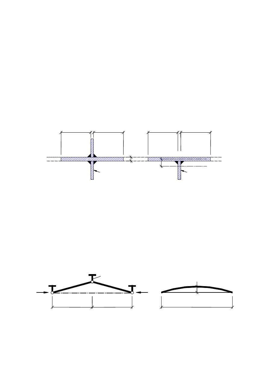
30
9 Stiffeners and detailing
9.1 General
(1)
This section gives design rules for stiffeners in plated structures which supplement the plate buckling
rules specified in sections 4 to 7.
NOTE: The National Annex may give further requirements on stiffeners for specific applications.
(2)
When checking the buckling resistance, the section of a stiffener may be taken as the gross area
comprising the stiffener plus a width of plate equal to 15εt but not more than the actual dimension available,
on each side of the stiffener avoiding any overlap of contributing parts to adjacent stiffeners, see Figure 9.1.
(3)
The axial force in a transverse stiffener should be taken as the sum of the force resulting from shear
(see 9.3.3(3)) and any external loads.
Figure 9.1: Effective cross-section of stiffener
9.2 Direct stresses
9.2.1 Minimum requirements for transverse stiffeners
(1)
In order to provide a rigid support for a plate with or without longitudinal stiffeners, intermediate
transverse stiffeners should satisfy the criteria given below.
(2)
The transverse stiffener should be treated as a simply supported member subject to lateral loading with
an initial sinusoidal imperfection w
0
equal to s/300, where s is the smallest of a
1
, a
2
or b, see Figure 9.2 ,
where a
1
and a
2
are the lengths of the panels adjacent to the transverse stiffener under consideration and b is
the height between the centroids of the flanges or span of the transverse stiffener. Eccentricities should be
accounted for.
1 Transverse stiffener
Figure 9.2: Transverse stiffener
(3)
The transverse stiffener should carry the deviation forces from the adjacent compressed panels under
the assumption that both adjacent transverse stiffeners are rigid and straight together with any external load
1
5
t
15
t
1
5
t
15
t
A
A
s
s
t
ε
ε
ε
ε
e
a
w
0
1
2
a
1
b
BS EN 1993-1-5:2006
EN 1993-1-5:2006 (E)
Licensed copy: BSI USER 06 Document Controller, Midmac Contracting Co. W.L.L, Version correct as of 26/05/2010
13:22, (c) BSI

31
and axial force according to the NOTE to 9.3.3(3). The compressed panels and the longitudinal stiffeners are
considered to be simply supported at the transverse stiffeners.
(4)
It should be verified that using a second order elastic method analysis both the following criteria are
satisfied at the ultimate limit state:
–
that the maximum stress in the stiffener should not exceed f
y
/
γ
M1;
–
that the additional deflection should not exceed b/300.
(5)
In the absence of an axial force in the transverse stiffener both the criteria in (4) above may be
assumed to be satisfied provided that the second moment of area I
st
of the transverse stiffeners is not less
than:
+
=
u
b
w
b
E
I
m
st
300
1
0
4
π
σ
(9.1)
where
+
=
2
1
,
,
1
1
a
a
b
N
Ed
p
cr
c
cr
m
σ
σ
σ
0
,
1
300
1
max
2
≥
=
M
y
b
f
e
E
u
γ
π
e
max
is the maximum distance from the extreme fibre of the stiffener to the centroid of the stiffener;
N
Ed
is the maximum compressive force of the adjacent panels but not less than the maximum
compressive stress times half the effective
p
compression area of the panel including stiffeners;
σ
cr,c
, σ
cr,p
are defined in 4.5.3 and Annex A.
NOTE: Where out of plane loading is applied to the transverse stiffeners reference should be made to
EN 1993-2 and EN 1993-1-7.
(6)
If the stiffener carries axial compression this should be increased by
2
2
/
π
σ
b
N
m
st
=
∆
in order to
account for deviation forces. The criteria in (4) apply but
∆N
st
need not be considered when calculating the
uniform stresses from axial load in the stiffener.
(7)
As a simplification the requirement of (4) may, in the absence of axial forces, be verified using a first
order elastic analysis taking account of the following additional equivalent uniformly distributed lateral load
q
acting on the length b:
(
)
el
m
w
w
q
+
=
0
4
σ
π
(9.2)
where
σ
m
is defined in (5) above;
w
0
is defined in Figure 9.2;
w
el
is the elastic deformation, that may be either determined iteratively or be taken as the maximum
additional deflection b/300.
(8)
Unless a more advanced method of analysis is carried out in order to prevent torsional buckling of
stiffeners with open cross-sections, the following criterion should be satisfied:
E
f
I
I
y
p
T
3
,
5
≥
(9.3)
where I
p
is the polar second moment of area of the stiffener alone around the edge fixed to the plate;
I
T
is the St. Venant torsional constant for the stiffener alone.
BS EN 1993-1-5:2006
EN 1993-1-5:2006 (E)
Licensed copy: BSI USER 06 Document Controller, Midmac Contracting Co. W.L.L, Version correct as of 26/05/2010
13:22, (c) BSI
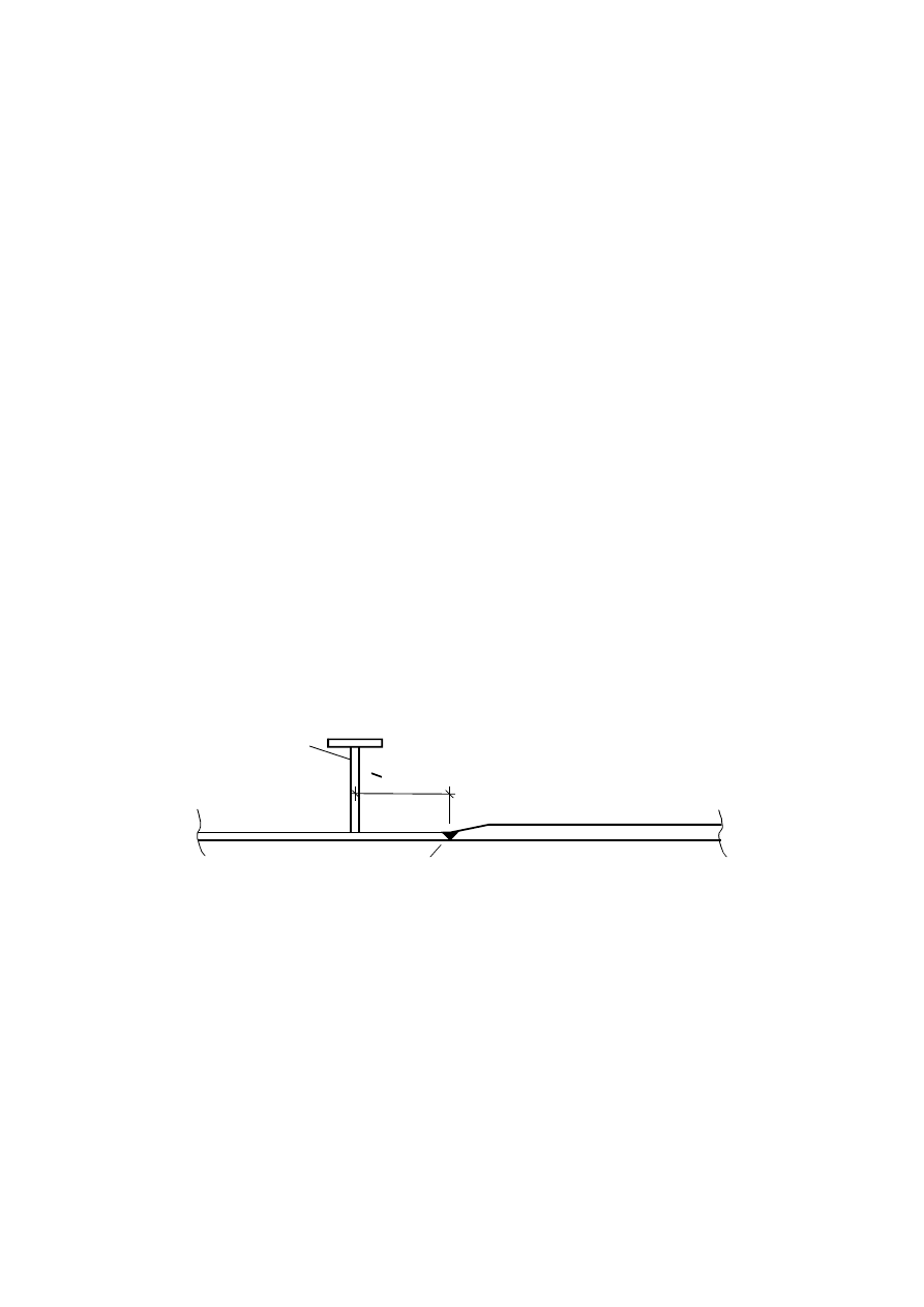
32
(9)
Where warping stiffness is considered stiffeners should either fulfil (8) or the criterion
σ
cr
≥
θ
f
y
(9.4)
where
σ
cr
is the elastic critical stress for torsional buckling not considering rotational restraint from the
plate;
θ
is a parameter to ensure class 3 behaviour.
NOTE: The parameter
θ
may be given in the National Annex. The value
θ
= 6 is recommended.
9.2.2 Minimum requirements for longitudinal stiffeners
(1)
The requirements concerning torsional buckling in 9.2.1(8) and (9) also apply to longitudinal
stiffeners.
(2)
Discontinuous longitudinal stiffeners that do not pass through openings made in the transverse
stiffeners or are not connected to either side of the transverse stiffeners should be:
–
used only for webs (i.e. not allowed in flanges);
–
neglected in global analysis;
–
neglected in the calculation of stresses;
–
considered in the calculation of the effective
p
widths of web sub-panels;
–
considered in the calculation of the elastic critical stresses.
(3)
Strength assessments for stiffeners should be performed according to 4.5.3 and 4.6.
9.2.3 Welded plates
(1)
Plates with changes in plate thickness should be welded adjacent to the transverse stiffener, see Figure
9.3. The effects of eccentricity need not be taken into account unless the distance to the stiffener from the
welded junction exceeds b
0
/2 or 200 mm whichever is the smallest, where b
0
is the width of the plate
between longitudinal stiffeners.
1 Transverse stiffener
2 Transverse weld
Figure 9.3: Welded plates
<min ( or 200 mm)
_
2
b
0
1
2
BS EN 1993-1-5:2006
EN 1993-1-5:2006 (E)
Licensed copy: BSI USER 06 Document Controller, Midmac Contracting Co. W.L.L, Version correct as of 26/05/2010
13:22, (c) BSI
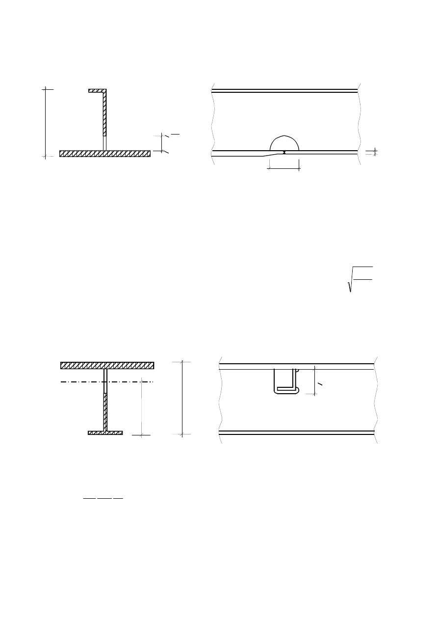
33
9.2.4 Cut outs in stiffeners
(1)
The dimensions of cut outs in longitudinal stiffeners should be as shown in Figure 9.4.
Figure 9.4: Cut outs in longitudinal stiffeners
(2)
The length
l
should not exceed:
min
6 t
≤
l
for flat stiffeners in compression
min
8 t
≤
l
for other stiffeners in compression
min
15 t
≤
l
for stiffeners without compression
where t
min
is the lesser of the plate thicknesses
(3)
The limiting values
l
in (2) for stiffeners in compression may be increased by
Ed
x
Rd
x
,
,
σ
σ
when
Rd
x
Ed
x
,
,
σ
σ
≤
and
min
15t
≤
l
.
Ed
x
,
σ
is the compression stress at the location of the cut-out
(4)
The dimensions of cut outs in transverse stiffeners should be as shown in Figure 9.5.
Figure 9.5: Cut outs in transverse stiffeners
(5)
The gross web adjacent to the cut out should resist a shear force V
Ed
, where
G
M
yk
net
Ed
b
f
e
I
V
π
γ
0
=
(9.5)
I
net
is the second moment of area for the net section of the transverse stiffener;
e
is the maximum distance from the underside of the flange plate to the neutral axis of net section,
see Figure 9.5;
b
G
is the length of the transverse stiffener between the flanges.
h
s
e
< 0,6h
s
h
s
< 40 mm
<
t
min
R
4
s
h
ˆ
‰
BS EN 1993-1-5:2006
EN 1993-1-5:2006 (E)
Licensed copy: BSI USER 06 Document Controller, Midmac Contracting Co. W.L.L, Version correct as of 26/05/2010
13:22, (c) BSI
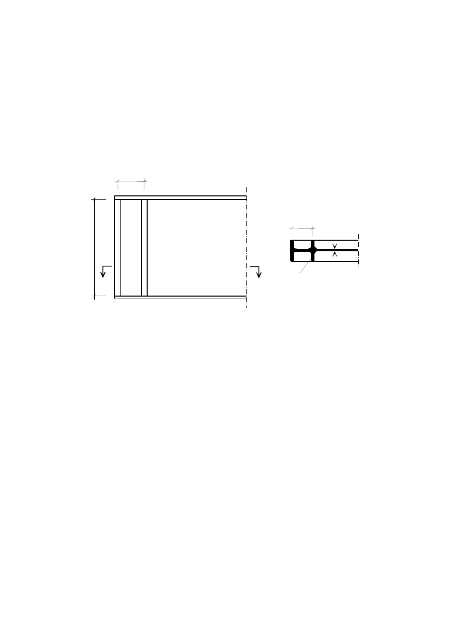
34
9.3 Shear
9.3.1 Rigid end post
(1)
The rigid end post (see Figure 5.1) should act as a bearing stiffener resisting the reaction from the
support (see 9.4), and should be designed as a short beam resisting the longitudinal membrane stresses in the
plane of the web.
NOTE: For the effects of eccentricity due to movements of bearings, see EN 1993-2.
(2)
A rigid end post should comprise of two double-sided transverse stiffeners that form the flanges of a
short beam of length h
w
, see Figure 5.1 (b). The strip of web plate between the stiffeners forms the web of
the short beam. Alternatively, a rigid end post may be in the form of a rolled section, connected to the end of
the web plate as shown in Figure 9.6.
1 Inserted section
Figure 9.6: Rolled section forming an end-post
(3)
Each double sided stiffener consisting of flats should have a cross sectional area of at least
e
t
h
w
/
4
2
,
where e is the centre to centre distance between the stiffeners and
w
h
e
1
,
0
>
, see Figure 5.1 (b). Where a
rolled section other than flats is used for the end-post its section modulus should be not less than
2
4 t
h
w
for
bending around a horizontal axis perpendicular to the web.
(4)
As an alternative the girder end may be provided with a single double-sided stiffener and a vertical
stiffener adjacent to the support so that the subpanel resists the maximum shear when designed with a non-
rigid end post.
9.3.2 Stiffeners acting as non-rigid end post
(1)
A non-rigid end post may be a single double sided stiffener as shown in Figure 5.1 (c). It may act as a
bearing stiffener resisting the reaction at the girder support (see 9.4).
9.3.3 Intermediate transverse stiffeners
(1)
Intermediate stiffeners that act as rigid supports to interior panels of the web should be designed for
strength and stiffness.
(2)
When flexible intermediate transverse stiffeners are used, their stiffness should be considered in the
calculation of k
τ
in 5.3(5).
h
w
e
A
A
t
e
A - A
1
BS EN 1993-1-5:2006
EN 1993-1-5:2006 (E)
Licensed copy: BSI USER 06 Document Controller, Midmac Contracting Co. W.L.L, Version correct as of 26/05/2010
13:22, (c) BSI
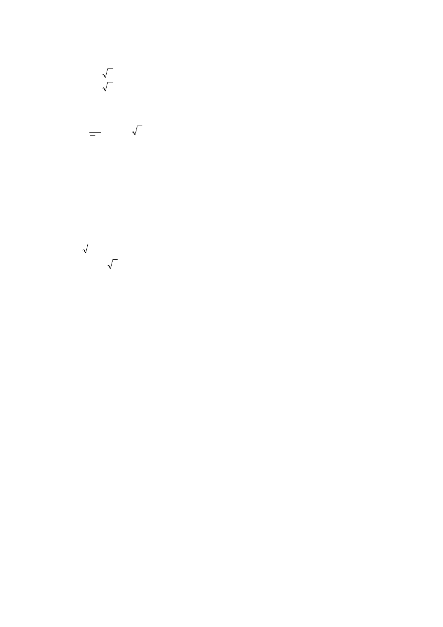
35
(3)
The effective section of intermediate stiffeners acting as rigid supports for web panels should have a
minimum second moment of area I
st
:
3
2
3
3
75
,
0
:
2
/
/
5
,
1
:
2
/
t
h
I
h
a
if
a
t
h
I
h
a
if
w
st
w
w
st
w
≥
≥
≥
<
(9.6)
NOTE:
Intermediate
rigid
stiffeners
may
be
designed
for
an
axial
force
equal
to
(
)
−
1
2
3
/
1
M
w
yw
w
Ed
t
h
f
V
γ
λ
according to 9.2.1(3). In the case of variable shear forces the check is
performed for the shear force at the distance 0,5h
w
from the edge of the panel with the largest shear force.
9.3.4 Longitudinal stiffeners
(1)
If longitudinal stiffeners are taken into account in the stress analysis they should be checked for direct
stresses for the cross sectional resistance.
9.3.5 Welds
(1)
The web to flange welds may be designed for the nominal shear flow
w
Ed
h
V
/
if V
Ed
does not exceed
(
)
1
3
/
M
w
yw
w
t
h
f
γ
χ
. For larger values V
Ed
the weld between flanges and webs should be designed for the
shear flow
(
)
1
3
/
M
yw
t
f
γ
η
.
(2)
In all other cases welds should be designed to transfer forces along and across welds making up
sections taking into account analysis method (elastic/plastic) and second order effects.
9.4 Transverse loads
(1)
If the design resistance of an unstiffened web is insufficient, transverse stiffeners should be provided.
(2)
The out-of-plane buckling resistance of the transverse stiffener under transverse loads and shear force
(see 9.3.3(3)) should be determined from 6.3.3 or 6.3.4 of EN 1993-1-1, using buckling curve c. When both
ends are assumed to be fixed laterally a buckling length ℓ of not less than 0,75h
w
should be used. A larger
value of ℓ should be used for conditions that provide less end restraint. If the stiffeners have cut outs at the
loaded end, the cross sectional resistance should be checked at this end.
(3)
Where single sided or other asymmetric stiffeners are used, the resulting eccentricity should be
allowed for using 6.3.3 or 6.3.4 of EN 1993-1-1. If the stiffeners are assumed to provide lateral restraint to
the compression flange they should comply with the stiffness and strength criteria in the design for lateral
torsional buckling.
BS EN 1993-1-5:2006
EN 1993-1-5:2006 (E)
Licensed copy: BSI USER 06 Document Controller, Midmac Contracting Co. W.L.L, Version correct as of 26/05/2010
13:22, (c) BSI
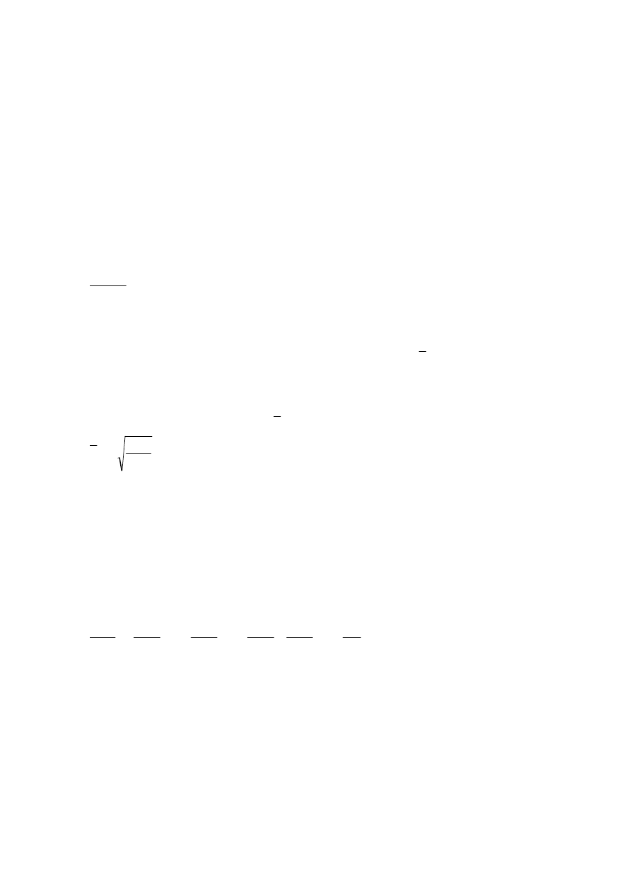
36
10 Reduced stress method
(1)
The reduced stress method may be used to determine the stress limits for stiffened or unstiffened
plates.
NOTE 1: This method is an alternative to the effective width method specified in section 4 to 7 in respect of the
following:
–
σ
x,Ed
,
σ
z,Ed
and
τ
Ed
are considered as acting together
–
the stress limits of the weakest part of the cross section may govern the resistance of the full cross section.
NOTE 2: The stress limits may also be used to determine equivalent effective areas. The National Annex may
give limits of application for the methods.
(2)
For unstiffened or stiffened panels subjected to combined stresses
σ
x,Ed
,
σ
z,Ed
and
τ
Ed
class 3 section
properties may be assumed, where
1
1
,
≥
M
k
ult
γ
α
ρ
(10.1)
where
α
ult,k
is the minimum load amplifier for the design loads to reach the characteristic value of
resistance of the most critical point of the plate, see (4);
ρ
is the reduction factor depending on the plate slenderness
p
λ
to take account of plate
buckling, see (5);
γ
M1
is the partial factor applied to this method.
(3)
The
p
λ
should be taken from
cr
k
ult
p
α
α
λ
,
=
(10.2)
where
α
cr
is the minimum load amplifier for the design loads to reach the elastic critical load of the plate
under the complete stress field, see (6)
NOTE 1: For calculating
α
cr
for the complete stress field, the stiffened plate may be modelled using the rules in
section 4 and 5 without reduction of the second moment of area of longitudinal stiffeners as specified in 5.3(4).
NOTE 2: When
α
cr
cannot be determined for the panel and its subpanels as a whole, separate checks for the
subpanel and the full panel may be applied.
(4)
In determining
α
ult,k
the yield criterion may be used for resistance:
2
,
,
2
,
2
,
2
,
3
1
+
−
+
=
y
Ed
y
Ed
z
y
Ed
x
y
Ed
z
y
Ed
x
k
ult
f
f
f
f
f
τ
σ
σ
σ
σ
α
(10.3)
where
σ
x,Ed
,
σ
z,Ed
and
τ
Ed
are the components of the stress field in the ultimate limit state.
NOTE: By using the equation (10.3) it is assumed that the resistance is reached when yielding occurs without
plate buckling.
(5)
The reduction factor
ρ may be determined using either of the following methods:
a) the minimum value of the following reduction factors:
ρ
x
for longitudinal stresses from 4.5.4(1) taking into account column-like behaviour where relevant;
ρ
z
for transverse stresses from 4.5.4(1) taking into account column-like behaviour where relevant;
χ
w
for shear stresses from
5.3
(1)
;
modified plate slenderness
ˆ
‰
ˆ
‰
BS EN 1993-1-5:2006
EN 1993-1-5:2006 (E)
Licensed copy: BSI USER 06 Document Controller, Midmac Contracting Co. W.L.L, Version correct as of 26/05/2010
13:22, (c) BSI

37
each calculated for the
p
λ
according to equation (10.2).
NOTE: This method leads to the verification formula:
2
2
1
1
,
1
,
2
1
,
2
1
,
/
3
/
/
/
/
ρ
γ
τ
γ
σ
γ
σ
γ
σ
γ
σ
≤
+
−
+
M
y
Ed
M
y
Ed
z
M
y
Ed
x
M
y
Ed
z
M
y
Ed
x
f
f
f
f
f
(10.4)
NOTE: For determining
ρ
z
for transverse stresses the rules in section 4 for direct stresses
σ
x
should be applied
to
σ
z
in the z-direction. For consistency section 6 should not be applied.
b) a value interpolated between the values of
ρ
x
,
ρ
z
and
χ
w
as determined in a) by using the formula for
α
ult,k
as interpolation function
NOTE: This method leads to the verification format:
1
/
3
/
/
/
/
2
1
1
,
1
,
2
1
,
2
1
,
≤
+
−
+
M
y
w
Ed
M
y
z
Ed
z
M
y
x
Ed
x
M
y
z
Ed
z
M
y
x
Ed
x
f
f
f
f
f
γ
χ
τ
γ
ρ
σ
γ
ρ
σ
γ
ρ
σ
γ
ρ
σ
(10.5)
NOTE 1: Since verification formulae (10.3), (10.4) and (10.5) include an interaction between shear force,
bending moment, axial force and transverse force, section 7 should not be applied.
NOTE 2: The National Annex may give further information on the use of equations (10.4) and (10.5). In case
of panels with tension and compression it is recommended to apply equations (10.4) and (10.5) only for the
compressive parts.
(6)
Where
α
cr
values for the complete stress field are not available and only
α
cr,i
values for the various
components of the stress field
σ
x,Ed
,
σ
z,Ed
and
τ
Ed
can be used, the
α
cr
value may be determined from:
2
/
1
2
,
2
,
2
,
2
,
,
,
,
1
2
1
2
1
4
1
4
1
4
1
4
1
1
+
−
+
−
+
+
+
+
+
+
+
+
=
τ
α
α
ψ
α
ψ
α
ψ
α
ψ
α
ψ
α
ψ
α
cr
z
cr
z
x
cr
x
z
cr
z
x
cr
x
z
cr
z
x
cr
x
cr
(10.6)
where
Ed
x
x
cr
x
cr
,
,
,
σ
σ
α
=
Ed
z
z
cr
z
cr
,
,
,
σ
σ
α
=
Ed
cr
cr
,
τ
τ
τ
α
=
and
σ
cr,x
,
σ
cr,z
,
τ
cr
,
ψ
x
and
ψ
z
are determined from sections 4 to 6.
(7)
Stiffeners and detailing of plate panels should be designed according to section 9.
ˆ
‰
‰
ˆ
BS EN 1993-1-5:2006
EN 1993-1-5:2006 (E)
modified plate slenderness
Licensed copy: BSI USER 06 Document Controller, Midmac Contracting Co. W.L.L, Version correct as of 26/05/2010
13:22, (c) BSI
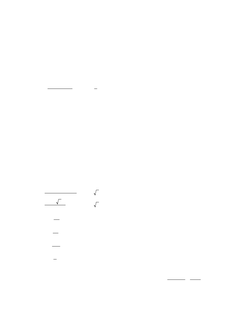
38
Annex A [informative] – Calculation of critical stresses for stiffened
plates
A.1
Equivalent orthotropic plate
(1)
Plates with at least three longitudinal stiffeners may be treated as equivalent orthotropic plates.
(2)
The elastic critical plate buckling stress of the equivalent orthotropic plate may be taken as:
E
p
p
cr
k
σ
σ
σ
,
,
=
(A.1)
where
(
)
[
]
MPa
in
b
t
b
t
E
E
2
2
2
2
2
190000
1
12
=
−
=
ν
π
σ
k
σ
,p
is the buckling coefficient according to orthotropic plate theory with the stiffeners smeared over
the plate;
b
is defined in Figure A.1;
t
is the thickness of the plate.
NOTE 1: The buckling coefficient k
σ
,p
is obtained either from appropriate charts for smeared stiffeners or
relevant computer simulations; alternatively charts for discretely located stiffeners may be used provided local
buckling in the subpanels can be ignored and treated separately.
NOTE 2:
σ
cr,p
is the elastic critical plate buckling stress at the edge of the panel where the maximum
compression stress occurs, see Figure A.1.
NOTE 3: Where a web is of concern,
the width b in
equations (A.1) and (A.2) should be replaced by h
w
.
NOTE 4: For stiffened plates with at least three equally spaced longitudinal stiffeners the plate buckling
coefficient k
σ,p
(global buckling of the stiffened panel) may be approximated by:
(
)
(
)(
)
(
)
(
)(
)
4
,
4
2
2
2
,
1
1
1
4
1
1
1
1
2
γ
α
δ
ψ
γ
γ
α
δ
ψ
α
γ
α
σ
σ
>
+
+
+
=
≤
+
+
−
+
+
=
if
k
if
k
p
p
(A.2)
with:
5
,
0
1
2
≥
=
σ
σ
ψ
p
sl
I
I
=
γ
p
sl
A
A
=
δ
5
,
0
≥
=
b
a
α
where:
sl
I
is the second moment of area of the whole stiffened plate;
p
I
is the second moment of area for bending of the plate
(
)
92
,
10
1
12
3
2
3
bt
bt
=
−
=
;
sl
A
is the sum of the gross areas of the individual longitudinal stiffeners;
A
p
p
A
is the gross area of the plate
bt
=
;
1
σ
is the larger edge stress;
2
σ
is the smaller edge stress;
ˆ
‰
‰
ˆ
ν
ˆ
‰
‰
ˆ
BS EN 1993-1-5:2006
EN 1993-1-5:2006 (E)
Licensed copy: BSI USER 06 Document Controller, Midmac Contracting Co. W.L.L, Version correct as of 26/05/2010
13:22, (c) BSI
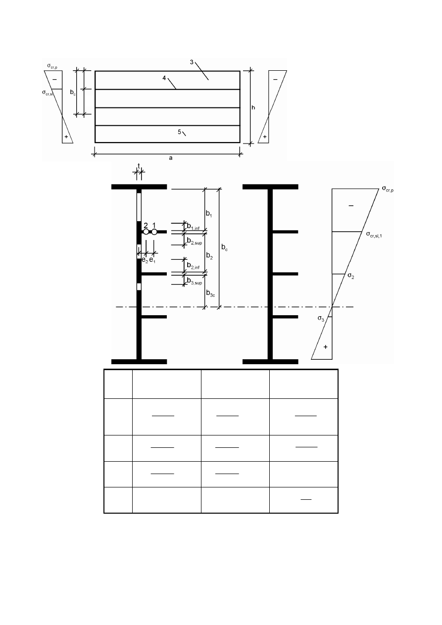
39
a
,
b
and
t
are as defined in Figure A.1.
1 centroid of
stiffener
2 centroid of
column =
stiffeners + accompanying
plating
3 subpanel
4 stiffener
5 plate thickness t
e
= max (e
1
, e
2
)
width for gross
area
width for effective
area according to
Table 4.1
condition for
ψ
i
b
1,inf
1
1
1
5
3
b
ψ
ψ
−
−
eff
b
,
1
1
1
5
3
ψ
ψ
−
−
0
,
1
,
,
1
>
=
p
cr
sl
cr
σ
σ
ψ
b
2,sup
2
2
5
2
b
ψ
−
eff
b
,
2
2
5
2
ψ
−
0
1
,
,
2
2
>
=
sl
cr
σ
σ
ψ
b
2,inf
2
2
2
5
3
b
ψ
ψ
−
−
eff
b
,
2
2
2
5
3
ψ
ψ
−
−
0
2
>
ψ
b
3,sup
0,4 b
3c
0,4 b
3c,eff
0
2
3
3
<
=
σ
σ
ψ
Figure A.1: Notations for longitudinally stiffened plates
ˆ
ˆ
‰
‰
,1
s
b
l
ˆ
‰
BS EN 1993-1-5:2006
EN 1993-1-5:2006 (E)
Licensed copy: BSI USER 06 Document Controller, Midmac Contracting Co. W.L.L, Version correct as of 26/05/2010
13:22, (c) BSI
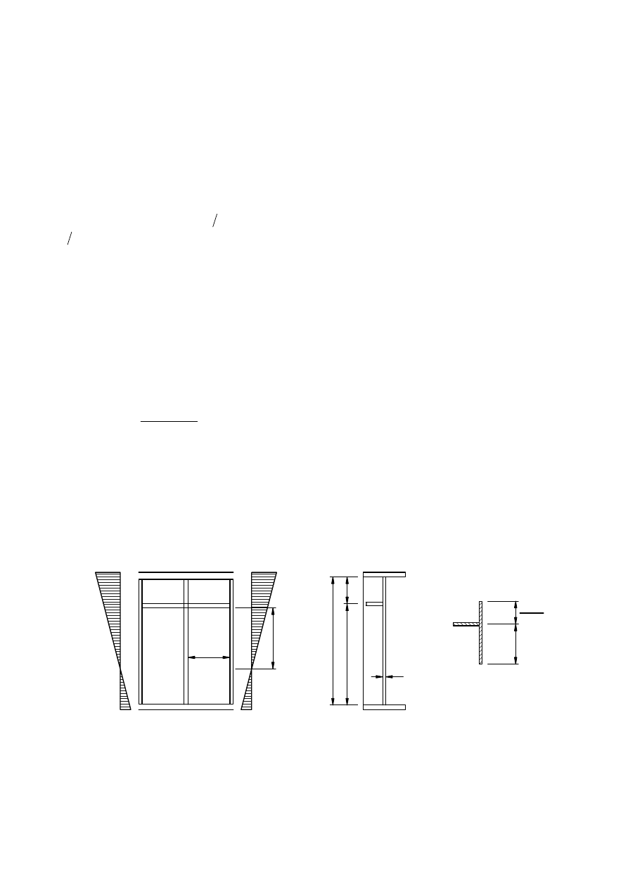
40
A.2
Critical plate buckling stress for plates with one or two stiffeners in the
compression zone
A.2.1
General procedure
(1)
If the stiffened plate has only one longitudinal stiffener in the compression zone the procedure in A.1
may be simplified by a fictitious isolated strut supported on an elastic foundation reflecting the plate effect in
the direction perpendicular to this strut. The elastic critical stress of the strut may be obtained from A.2.2.
(2)
For calculation of
1
,
l
s
A
and
1
,
l
s
I
the gross cross-section of the column should be taken as the gross
area of the stiffener and adjacent parts of the plate described as follows. If the subpanel is fully in
compression, a portion
(
) (
)
ψ
ψ
−
−
5
3
of its width b
1
should be taken at the edge of the panel and
(
)
ψ
−
5
2
at the edge with the highest stress. If the stress changes from compression to tension within the
subpanel, a portion 0,4 of the width b
c
of the compressed part of this subpanel should be taken as part of the
column, see Figure A.2 and also Table 4.1.
ψ
is the stress ratio relative to the subpanel in consideration.
(3)
The effective
p
cross-sectional area
eff
s
A
,
l
of the column should be taken as the effective
p
cross-section
of the stiffener and the adjacent effective
p
parts of the plate, see Figure A.1. The slenderness of the plate
elements in the column may be determined according to 4.4(4), with σ
com,Ed
calculated for the gross cross-
section of the plate.
(4)
If
ρ
c
f
y
/
γ
M1
,with ρ
c
determined according to 4.5.4(1), is greater than the average stress in the column
σ
com,Ed
no further reduction of the effective
p
area of the column should be made. Otherwise the effective area
in (4.6) should be modified as follows:
1
,
1
,
,
,
M
Ed
com
sl
y
c
loc
eff
c
A
f
A
γ
σ
ρ
=
(A.3)
(5)
The reduction mentioned in A.2.1(4) should be applied only to the area of the column. No reduction
need be applied to other compressed parts of the plate, except for checking buckling of subpanels.
(6)
As an alternative to using an effective
p
area according to A.2.1(4), the resistance of the column may be
determined from A.2.1(5) to (7) and checked to ensure that it exceeds the average stress σ
com,Ed
.
NOTE: The method outlined in (6) may be used in the case of multiple stiffeners in which the restraining effect
from the plate is neglected, that is the fictitious column is considered free to buckle out of the plane of the web.
a
a.
b.
b
c
b
b
b
2
1
t
c.
1
c
b
0,4 b
(3- )
ψ
ψ
(5- )
Figure A.2: Notations for a web plate with single stiffener in the compression
zone
(7)
If the stiffened plate has two longitudinal stiffeners in the compression zone, the one stiffener
procedure described in A.2.1(1) may be applied, see Figure A.3. First, it is assumed that one of the stiffeners
1
,
l
s
A
ˆ
‰
BS EN 1993-1-5:2006
EN 1993-1-5:2006 (E)
Licensed copy: BSI USER 06 Document Controller, Midmac Contracting Co. W.L.L, Version correct as of 26/05/2010
13:22, (c) BSI
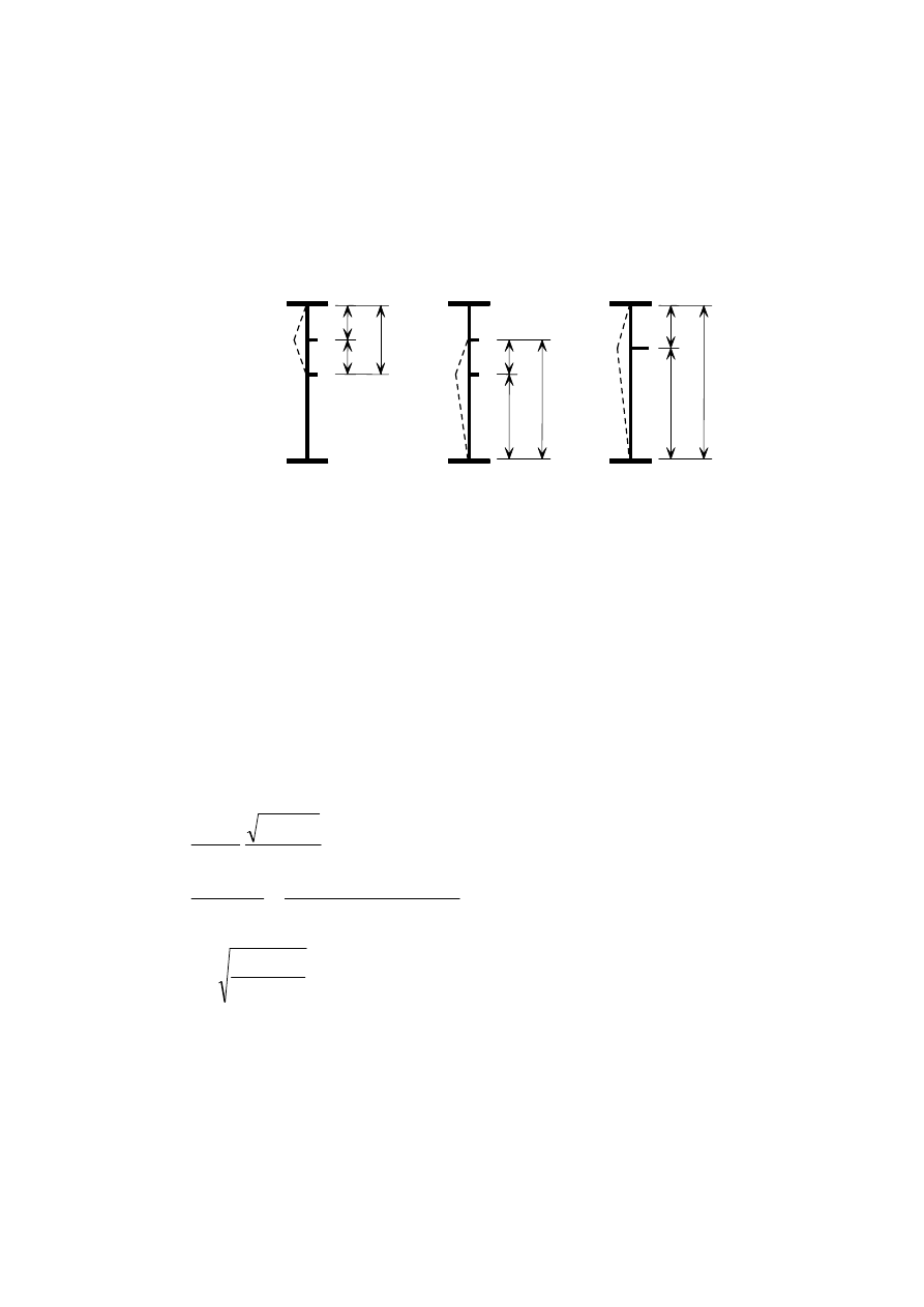
41
buckles while the other one acts as a rigid support. Buckling of both the stiffeners simultaneously is
accounted for by considering a single lumped stiffener that is substituted for both individual ones such that:
a) its cross-sectional area and its second moment of area
are respectively the sum of that for the
individual stiffeners
b) it is positioned at the location of the resultant of the respective forces in the individual stiffeners
For each of these situations illustrated in Figure A.3 a relevant value of σ
cr.p
is computed, see A.2.2(1), with
*
1
1
b
b
=
and
*
2
2
b
b
=
and
*
2
*
1
*
b
b
B
+
=
, see Figure A.3.
Cross-sectional area
I
s
A
,
l
II
s
A
,
l
II
s
I
s
A
A
,
,
l
l
+
Second moment of area
I
s
I
,
l
II
s
I
,
l
II
s
I
s
I
I
,
,
l
l
+
Figure A.3: Notations for plate with two stiffeners in the compression zone
A.2.2
Simplified model using a column restrained by the plate
(1)
In the case of a stiffened plate with one longitudinal stiffener located in the compression zone, the
elastic critical buckling stress of the stiffener can be calculated as follows ignoring stiffeners in the tension
zone:
(
)
c
s
s
s
s
cr
c
s
s
s
cr
a
a
if
b
b
A
a
b
t
E
a
A
I
E
a
a
if
b
b
b
t
I
A
E
−
+
=
≥
=
2
2
2
1
1
,
2
2
2
3
2
1
,
1
,
2
,
2
1
3
1
,
1
,
,
1
4
05
,
1
l
l
l
l
l
l
l
ν
π
π
σ
σ
(A.4)
with
4
3
2
2
2
1
1
,
33
,
4
b
t
b
b
I
a
s
c
l
=
where
1
,
l
s
A
is the gross area of the column obtained from A.2.1(2)
1
,
l
s
I
is the second moment of area of the gross cross-section of the column defined in A.2.1(2)
about an axis through its centroid and parallel to the plane of the plate;
b
1
, b
2
are the distances from the longitudinal edges of the web to the stiffener (b
1
+b
2
= b).
(2)
In the case of a stiffened plate with two longitudinal stiffeners located in the compression zone the
elastic critical plate buckling stress should be taken as the lowest of those computed for the three cases using
b
b
b
*
*
*
*
*
*
*
*
*
1
2
2
2
B
I
I
II
II
Stiffener I
b
1
1
B
Stiffener II
Lumped stiffener
b
B
b
ˆ
‰
s
I
l
<
ˆ
‰
note deleted
ˆ
‰
BS EN 1993-1-5:2006
EN 1993-1-5:2006 (E)
Licensed copy: BSI USER 06 Document Controller, Midmac Contracting Co. W.L.L, Version correct as of 26/05/2010
13:22, (c) BSI
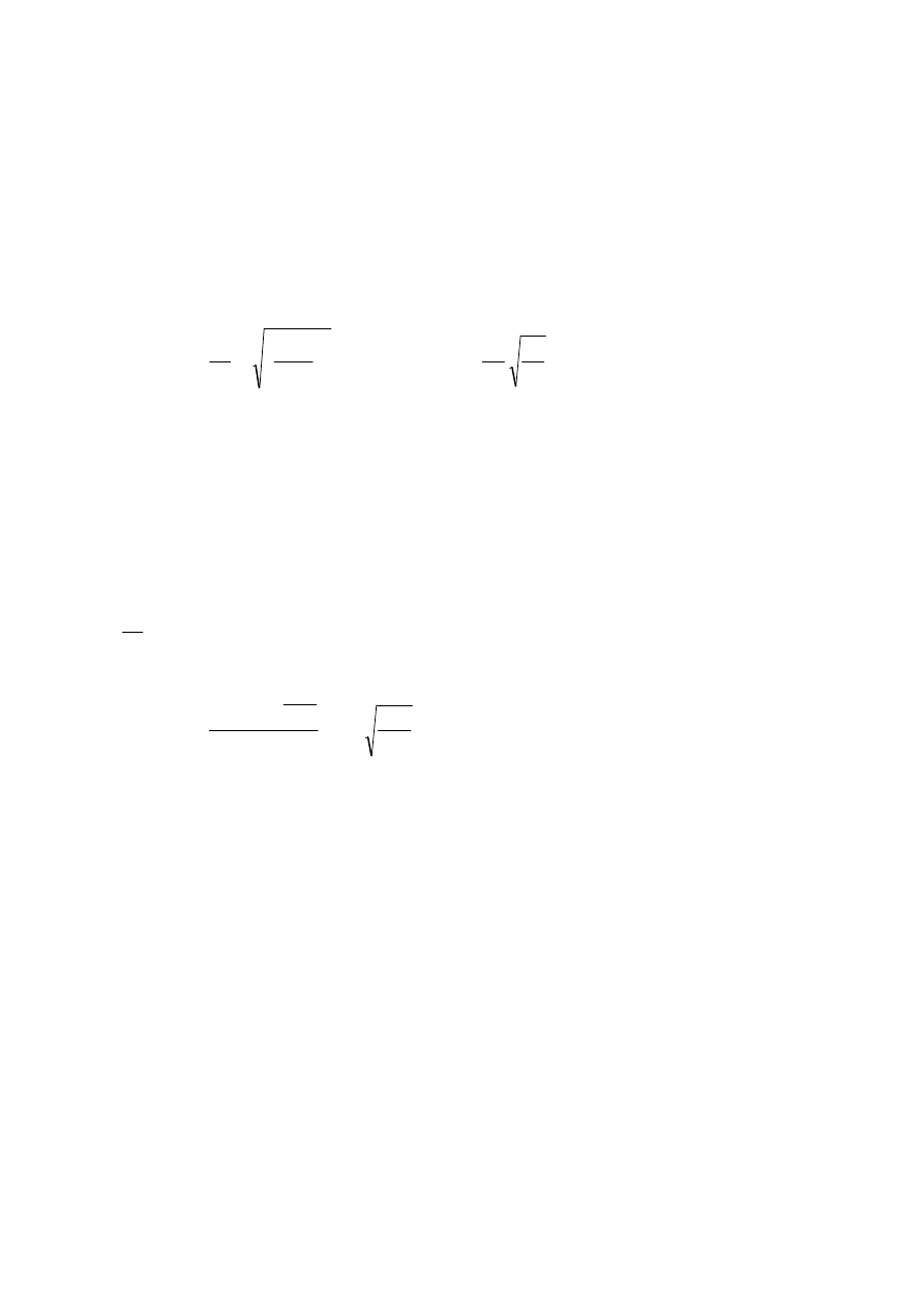
42
equation (A.4) with
*
1
1
b
b
=
,
*
2
2
b
b
=
and
*
B
b
=
. The stiffeners in the tension zone should be ignored in the
calculation.
A.3
Shear buckling coefficients
(1)
For plates with rigid transverse stiffeners and without longitudinal stiffeners or with more than two
longitudinal stiffeners, the shear buckling coefficient k
τ
can be obtained as follows:
(
)
(
)
1
/
/
34
,
5
00
,
4
1
/
/
00
,
4
34
,
5
2
2
<
+
+
=
≥
+
+
=
w
s
w
w
s
w
h
a
when
k
a
h
k
h
a
when
k
a
h
k
l
l
τ
τ
τ
τ
(A.5)
where
3
4
3
3
2
1
,
2
9
w
s
w
s
w
s
h
I
t
than
less
not
but
h
t
I
a
h
k
l
l
l
=
τ
a
is the distance between transverse stiffeners (see Figure 5.3);
l
s
I
is the second moment of area of the longitudinal stiffener about the z–z axis, see Figure 5.3 (b).
For webs with
longitudinal stiffeners, not necessarily equally spaced,
l
s
I
is the sum of
the stiffness of the individual stiffeners.
NOTE: No intermediate non-rigid transverse stiffeners are allowed for in equation (A.5).
(2)
The equation (A.5) also applies to plates with one or two longitudinal stiffeners, if the aspect ratio
w
h
a
=
α
satisfies
3
≥
α
. For plates with one or two longitudinal stiffeners and an aspect ratio
3
<
α
the
shear buckling coefficient should be taken from:
3
3
2
3
2
,
2
18
,
0
3
,
6
1
,
4
w
s
w
s
h
t
I
h
t
I
k
l
l
+
+
+
=
α
τ
(A.6)
ˆ
‰
BS EN 1993-1-5:2006
EN 1993-1-5:2006 (E)
Licensed copy: BSI USER 06 Document Controller, Midmac Contracting Co. W.L.L, Version correct as of 26/05/2010
13:22, (c) BSI
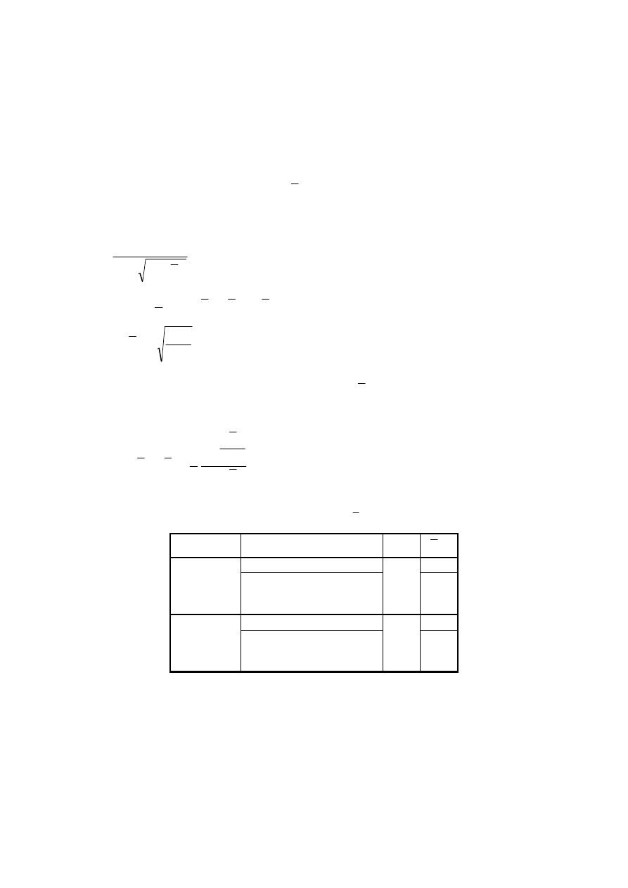
43
Annex B [informative] – Non-uniform members
B.1
General
(1)
The rules in section 10 are applicable to webs of members with non parallel flanges as in haunched
beams and to webs with regular or irregular openings and non orthogonal stiffeners.
(2)
α
ult
and
α
crit
may be obtained from FE-methods, see Annex C.
(3)
The reduction factors
ρ
x
,
ρ
z
and χ
w
for
p
λ
may be obtained from the appropriate plate buckling
curves, see sections 4 and 5.
NOTE: The reduction factor
ρ may be obtained as follows:
p
p
p
λ
φ
φ
ρ
−
+
=
2
1
(B.1)
where
(
)
(
)
p
p
p
p
p
λ
λ
λ
α
φ
+
−
+
=
0
1
2
1
and
cr
k
ult
p
α
α
λ
,
=
This procedure applies to
ρ
x
,
ρ
z
and χ
w
. The values of
0
p
λ
and
p
α
are given in Table B.1. These
values have been calibrated against the plate buckling curves in sections 4 and 5 and give a direct
correlation to the equivalent geometric imperfection, by :
(
)
p
M
p
p
p
p
t
e
λ
ρ
γ
λ
ρ
λ
λ
α
−
−
−
=
1
1
6
1
0
0
(B.2)
Table B.1: Values for
0
p
λ
and α
p
Product
predominant buckling mode
p
α
0
p
λ
direct stress for
ψ
≥ 0
0,70
hot rolled
direct stress for
ψ
< 0
shear
transverse stress
0,13
0,80
direct stress for
ψ
≥ 0
0,70
welded or
cold formed
direct stress for
ψ
< 0
shear
transverse stress
0,34
0,80
BS EN 1993-1-5:2006
EN 1993-1-5:2006 (E)
Licensed copy: BSI USER 06 Document Controller, Midmac Contracting Co. W.L.L, Version correct as of 26/05/2010
13:22, (c) BSI

44
B.2
Interaction of plate buckling and lateral torsional buckling
(1)
The method given in B.1 may be extended to the verification of combined plate buckling and lateral
torsional buckling of members by calculating
α
ult
and
α
cr
as follows:
α
ult
is the minimum load amplifier for the design loads to reach the characteristic value of resistance of the
most critical cross section, neglecting any plate buckling and lateral torsional buckling;
α
cr
is the minimum load amplifier for the design loads to reach the
elastic critical
of the
member including plate buckling and lateral torsional buckling modes.
(2)
When
α
cr
contains lateral torsional buckling modes, the reduction factor
ρ
used should be the
minimum of the reduction factor according to B.1(3) and the χ
LT
– value for lateral torsional buckling
according to 6.3.3 of EN 1993-1-1.
ˆ
‰
loading
ˆ
‰
BS EN 1993-1-5:2006
EN 1993-1-5:2006 (E)
Licensed copy: BSI USER 06 Document Controller, Midmac Contracting Co. W.L.L, Version correct as of 26/05/2010
13:22, (c) BSI
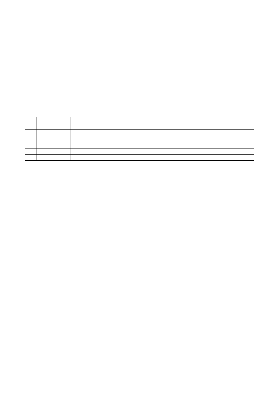
45
Annex C [informative] – Finite Element Methods of analysis (FEM)
C.1
General
(1)
Annex C gives guidance on the use of FE-methods for ultimate limit state, serviceability limit state or
fatigue verifications of plated structures.
NOTE 1: For FE-calculation of shell structures see EN 1993-1-6.
NOTE 2: This guidance is intended for engineers who are experienced in the use of Finite Element methods.
(2)
The choice of the FE-method depends on the problem to be analysed and based on the following
assumptions:
Table C.1: Assumptions for FE-methods
No
Material
behaviour
Geometric
behaviour
Imperfections,
see section C.5
Example of use
1
linear
linear
no
elastic shear lag effect, elastic resistance
2
non linear
linear
no
plastic resistance in ULS
3
linear
non linear
no
critical plate buckling load
4
linear
non linear
yes
elastic plate buckling resistance
5
non linear
non linear
yes
elastic-plastic resistance in ULS
C.2
Use
(1)
In using FEM for design special care should be taken to
–
the modelling of the structural component and its boundary conditions;
–
the choice of software and documentation;
–
the use of imperfections;
–
the modelling of material properties;
–
the modelling of loads;
–
the modelling of limit state criteria;
–
the partial factors to be applied.
NOTE: The National Annex may define the conditions for the use of FEM analysis in design.
C.3
Modelling
(1)
The choice of FE-models (shell models or volume models) and the size of mesh determine the
accuracy of results. For validation sensitivity checks with successive refinement may be carried out.
(2)
The FE-modelling may be carried out either for:
–
the component as a whole or
–
a substructure as a part of the whole structure.
NOTE: An example for a component could be the web and/or the bottom plate of continuous box girders in the
region of an intermediate support where the bottom plate is in compression. An example for a substructure could
be a subpanel of a bottom plate subject to biaxial stresses.
(3)
The boundary conditions for supports, interfaces and applied loads should be chosen such that results
obtained are conservative.
BS EN 1993-1-5:2006
EN 1993-1-5:2006 (E)
Licensed copy: BSI USER 06 Document Controller, Midmac Contracting Co. W.L.L, Version correct as of 26/05/2010
13:22, (c) BSI
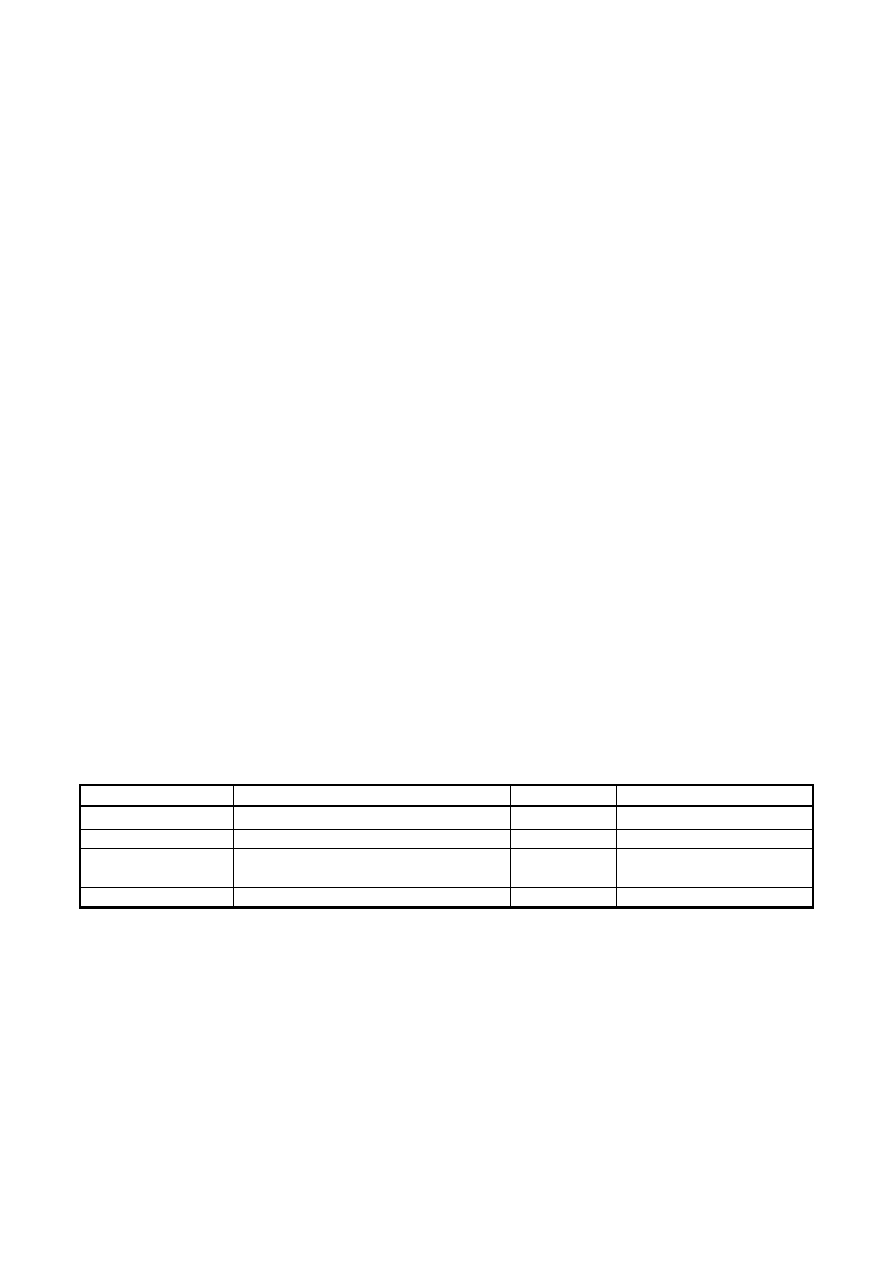
46
(4)
Geometric properties should be taken as nominal.
(5)
All imperfections should be based on the shapes and amplitudes as given in section C.5.
(6)
Material properties should conform to C.6(2).
C.4
Choice of software and documentation
(1)
The software should be suitable for the task and be proven reliable.
NOTE: Reliability can be proven by appropriate bench mark tests.
(2)
The mesh size, loading, boundary conditions and other input data as well as the output should be
documented in a way that they can be reproduced by third parties.
C.5
Use of imperfections
(1)
Where imperfections need to be included in the FE-model these imperfections should include both
geometric and structural imperfections.
(2)
Unless a more refined analysis of the geometric imperfections and the structural imperfections is
carried out, equivalent geometric imperfections may be used.
NOTE 1: Geometric imperfections may be based on the shape of the critical plate buckling modes with
amplitudes given in the National Annex. 80 % of the geometric fabrication tolerances is recommended.
NOTE 2: Structural imperfections in terms of residual stresses may be represented by a stress pattern from the
fabrication process with amplitudes equivalent to the mean (expected) values.
(3)
The direction of the applied imperfection should be such that the lowest resistance is obtained.
(4)
For applying equivalent geometric imperfections Table C.2 and Figure C.1 may be used.
Table C.2: Equivalent geometric imperfections
Type of imperfection
Component
Shape
Magnitude
global
member with length
l
bow
see EN 1993-1-1, Table 5.1
global
longitudinal stiffener with length a
bow
min (a/400, b/400)
local
panel or subpanel with short span a or b
buckling
shape
min (a/200, b/200)
local
stiffener or flange subject to twist
bow twist
1 / 50
BS EN 1993-1-5:2006
EN 1993-1-5:2006 (E)
Licensed copy: BSI USER 06 Document Controller, Midmac Contracting Co. W.L.L, Version correct as of 26/05/2010
13:22, (c) BSI
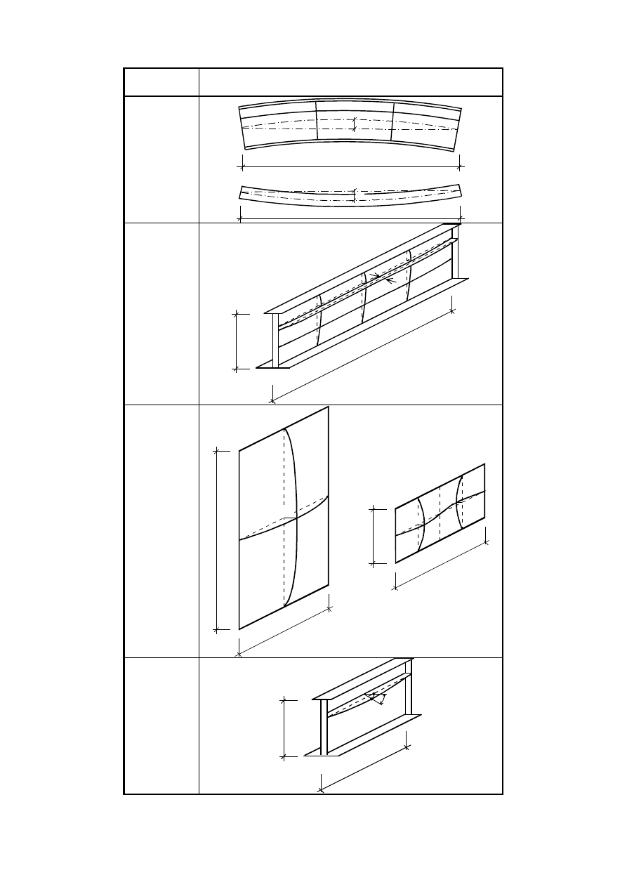
47
Type of
imperfection
Component
global
member with
length ℓ
global
longitudinal
stiffener with
length a
local panel or
subpanel
local stiffener
or flange
subject to
twist
Figure C.1: Modelling of equivalent geometric imperfections
l
e
0z
e
0y
l
b
a
e
0w
b
a
b
a
e
0w
e
0w
b
a
__
50
1
BS EN 1993-1-5:2006
EN 1993-1-5:2006 (E)
Licensed copy: BSI USER 06 Document Controller, Midmac Contracting Co. W.L.L, Version correct as of 26/05/2010
13:22, (c) BSI
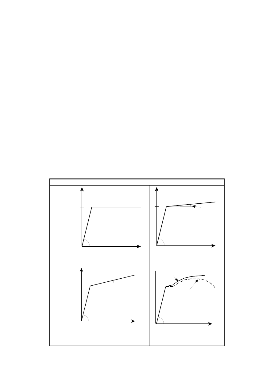
48
(5)
In combining imperfections a leading imperfection should be chosen and the accompanying
imperfections may have their values reduced to 70%.
NOTE 1: Any type of imperfection should be taken as the leading imperfection and the others may be taken as
the accompanying imperfections.
NOTE 2: Equivalent geometric imperfections may be substituted by the appropriate fictitious forces acting on
the member.
C.6
Material properties
(1)
Material properties should be taken as characteristic values.
(2)
Depending on the accuracy and the allowable strain required for the analysis the following
assumptions for the material behaviour may be used, see Figure C.2:
a) elastic-plastic without strain hardening;
b) elastic-plastic with a nominal plateau slope;
c) elastic-plastic with linear strain hardening;
d) true stress-strain curve modified from the test results as follows:
(
)
(
)
ε
ε
ε
σ
σ
+
=
+
=
1
1
n
true
true
l
(C.1)
Model
with
yielding
plateau
1 tan
-1
(E/10000)
(or similarly small value)
with
strain-
hardening
1 true stress-strain curve
2 stress-strain curve from tests
Figure C.2: Modelling of material behaviour
,
a)
F
f
y
tan
-1
(E)
,
b)
F
f
y
1
tan
-1
(E)
,
c)
F
f
y
tan
-1
(E/100)
tan
-1
(E)
1
,
d)
F
f
y
2
tan
-1
(E)
BS EN 1993-1-5:2006
EN 1993-1-5:2006 (E)
Licensed copy: BSI USER 06 Document Controller, Midmac Contracting Co. W.L.L, Version correct as of 26/05/2010
13:22, (c) BSI

49
NOTE: For the elastic modulus E the nominal value is relevant.
C.7
Loads
(1)
The loads applied to the structures should include relevant load factors and load combination factors.
For simplicity a single load multiplier
α
may be used.
C.8
Limit state criteria
(1)
The ultimate limit state criteria should be used as follows:
1. for structures susceptible to buckling:
attainment of the maximum load.
2. for regions subjected to tensile stresses:
attainment of a limiting value of the principal membrane strain.
NOTE 1:
The National Annex may specify the limiting of principal strain. A value of 5% is
recommended.
NOTE 2:
Other criteria may be used, e.g. attainment of the yielding criterion or limitation of the
yielding zone.
C.9
Partial factors
(1)
The load magnification factor
α
u
to the ultimate limit state should be sufficient to achieve the required
reliability.
(2)
The magnification factor
α
u
should consist of two factors as follows:
1.
α
1
to cover the model uncertainty of the FE-modelling used. It should be obtained from evaluations
of test calibrations, see Annex D to EN 1990;
2.
α
2
to cover the scatter of the loading and resistance models. It may be taken as γ
M1
if instability
governs and γ
M2
if fracture governs.
(3) It should be verified that:
α
u
>
α
1
α
2
(C.2)
NOTE: The National Annex may give information on γ
M1
and γ
M2
. The use of γ
M1
and γ
M2
as specified in the
relevant parts of EN 1993 is recommended.
BS EN 1993-1-5:2006
EN 1993-1-5:2006 (E)
Licensed copy: BSI USER 06 Document Controller, Midmac Contracting Co. W.L.L, Version correct as of 26/05/2010
13:22, (c) BSI
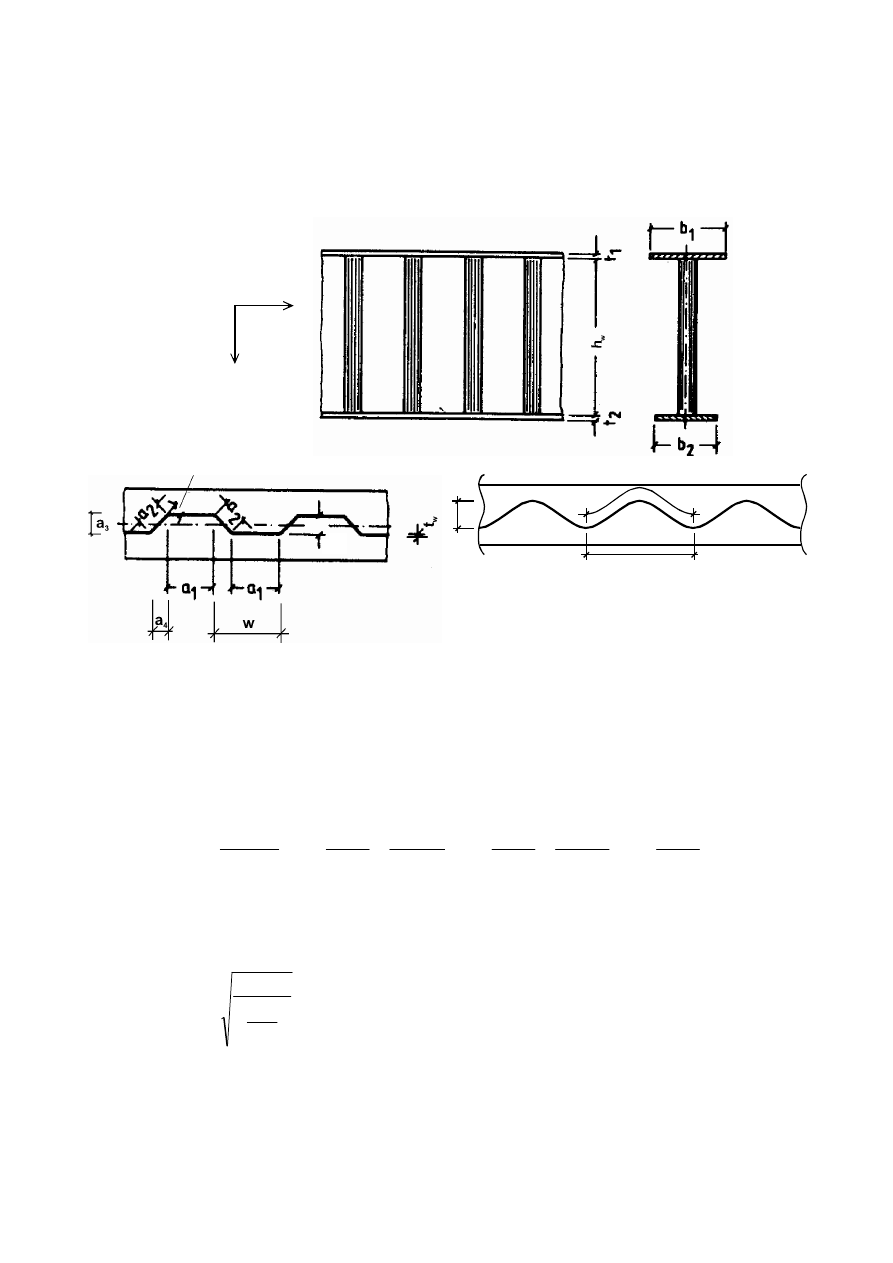
50
Annex D [informative] – Plate girders with corrugated webs
D.1
General
(1)
Annex D covers design rules for I-girders with trapezoidal or sinusoidal corrugated webs, see Figure
D.1.
x
z
α>30°
Figure D.1: Geometric notations
D.2
Ultimate limit state
D.2.1
Moment of resistance
(1)
The moment of resistance
due to bending should be taken as the minimum of the following:
+
+
+
+
+
+
=
4
4
4
3
4
4
4
2
1
4
4
4
3
4
4
4
2
1
4
4
4
3
4
4
4
2
1
flange
n
compressio
w
M
yf
flange
n
compressio
w
M
r
yf
flange
tension
w
M
r
yf
t
t
h
f
t
b
t
t
h
f
t
b
t
t
h
f
t
b
2
;
2
;
2
min
2
1
1
1
1
2
1
0
,
1
1
2
1
0
,
2
2
γ
χ
γ
γ
(D.1)
where f
yf, r
is the value of yield stress reduced due to transverse moments in the flanges
f
yf,r
= f
yf
f
T
( )
0
4
,
0
1
M
yf
z
x
T
f
M
f
γ
σ
−
=
σ
x
(M
z
) is the stress due to the transverse moment in the flange
χ
is the reduction factor for out of plane buckling according to 6.3 of EN 1993-1-1
NOTE 1: The transverse moment M
z
results from the shear flow in flanges as indicated in Figure D.2.
NOTE 2: For sinusoidally corrugated webs f
T
is 1,0.
a
3
2w
2s
ˆ
‰
text deleted
My,
Rd
ˆ
‰
My,
Rd
ˆ
‰
BS EN 1993-1-5:2006
EN 1993-1-5:2006 (E)
Licensed copy: BSI USER 06 Document Controller, Midmac Contracting Co. W.L.L, Version correct as of 26/05/2010
13:22, (c) BSI
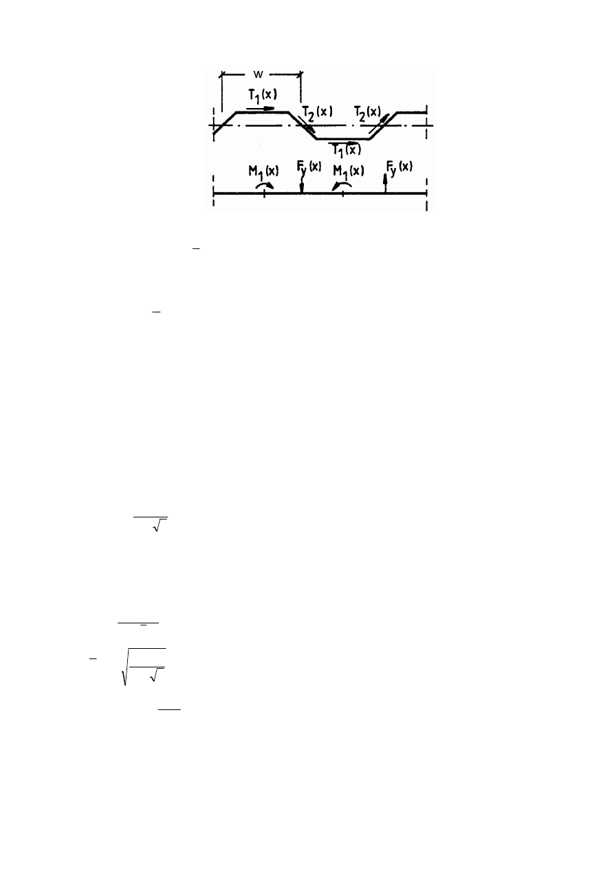
51
Figure D.2: Transverse actions due to shear flow introduction into the flange
(2)
The effective
p
area of the compression flange should be determined from 4.4(1) using the larger value
of the slenderness parameter
p
λ
defined in 4.4(2).
The buckling factor k
σ
should be taken as the larger of
:
a)
2
43
,
0
+
=
a
b
k
σ
(D.2)
where b is the maximum width of the outstand from the toe of the weld to the free edge
4
1
2a
a
a
+
=
b)
60
,
0
=
σ
k
(D.3)
D.2.2
Shear resistance
(1)
The shear resistance
should be taken as:
w
w
M
yw
c
t
h
f
3
1
γ
χ
=
(D.4)
where
c
χ
is the lesser of the values of reduction factors for local buckling
l
,
c
χ
and global buckling
g
c
,
χ
obtained from (2) and (3)
(2)
The reduction factor
l
,
c
χ
for local buckling should be calculated from:
0
,
1
9
,
0
15
,
1
,
,
≤
+
=
l
l
c
c
λ
χ
(D.5)
where
3
,
,
l
l
cr
yw
c
f
τ
λ
=
(D.6)
2
max
,
83
,
4
=
a
t
E
w
cr l
τ
(D.7)
a
max
should be taken as the greater of a
1
and a
2
.
a) and b)
ˆ
‰
ˆ
‰
text deleted
ˆ
‰
V
bw,Rd
ˆ
‰
V
bw,Rd
ˆ
‰
BS EN 1993-1-5:2006
EN 1993-1-5:2006 (E)
Licensed copy: BSI USER 06 Document Controller, Midmac Contracting Co. W.L.L, Version correct as of 26/05/2010
13:22, (c) BSI
52
NOTE: For sinusoidally corrugated webs the National Annex may give information on the calculation of
τ
cr, ℓ
and
l
,
c
χ
.
The use of the following equation is recommended:
2
2
2
3
,
)
1
(
12
)
34
,
5
(
−
+
=
s
t
v
E
t
h
s
a
w
w
w
cr
π
τ
l
where
w
is the length of one half wave, see Figure D.1,
s
is the unfolded length of one half wave, see Figure D.1
(3)
The reduction factor
g
c
,
χ
for global buckling should be taken as
0
,
1
5
,
0
5
,
1
2
,
,
≤
+
=
g
c
g
c
λ
χ
(D.8)
where
3
,
,
g
cr
yw
g
c
f
τ
λ
=
(D.9)
4
3
2
,
4
,
32
z
x
w
w
g
cr
D
D
h
t
=
τ
(D.10)
(
)
s
w
t
E
D
w
x
2
3
1
12
ν
−
=
w
I
E
D
z
z
=
I
z
second moment of area of one corrugation of length w, see Figure D.1
NOTE 1: s and I
z
are related to the actual shape of the corrugation.
NOTE 2: Equation (D.10) is valid for plates that are assumed to be hinged at the edges.
D.2.3
Requirements for end stiffeners
(1)
Bearing stiffeners should be designed according to section 9.
‰
ˆ
BS EN 1993-1-5:2006
EN 1993-1-5:2006 (E)
Licensed copy: BSI USER 06 Document Controller, Midmac Contracting Co. W.L.L, Version correct as of 26/05/2010
13:22, (c) BSI
53
Annex E [normative] – Alternative methods for determining effective
cross sections
E.1
Effective areas for stress levels below the yield strength
(1)
As an alternative to the method given in 4.4(2) the following formulae may be applied to determine
effective areas at stress levels lower than the yield strength:
a) for internal compression elements:
(
)
(
)
(
)
6
,
0
18
,
0
/
3
055
,
0
1
p
red
p,
p
red
p,
red
p,
−
−
+
+
−
=
λ
λ
λ
λ
λ
ψ
ρ
but
ρ
≤ 1,0
(E.1)
b) for outstand compression elements:
(
)
(
)
6
,
0
18
,
0
/
188
,
0
1
p
red
p,
p
red
p,
red
p,
−
−
+
−
=
λ
λ
λ
λ
λ
ρ
but
ρ
≤ 1,0
(E.2)
For notations see 4.4(2) and 4.4(4). For calculation of resistance to global buckling 4.4(5) applies.
E.2
Effective areas for stiffness
(1)
For the calculation of effective areas for stiffness the serviceability limit state slenderness
ser
p
,
λ
may
be calculated from:
y
ser
Ed
com
p
ser
p
f
,
,
,
σ
λ
λ
=
(E.3)
where
σ
com,Ed,ser
is defined as the maximum compressive stress (calculated on the basis of the effective cross
section) in the relevant element under loads at serviceability limit state.
(2)
The second moment of area may be calculated by an interpolation of the gross cross section and the
effective cross section for the relevant load combination using the expression:
(
)
(
)
ser
Ed
com
eff
gr
ser
Ed
com
gr
gr
eff
I
I
I
I
,
,
,
,
σ
σ
σ
−
−
=
(E.4)
where I
gr
is the second moment of area of the gross cross section
σ
gr
is the maximum bending stress at serviceability limit states based on the gross cross section
I
eff
(
σ
com,Ed,ser
) is the second moment of area of the effective cross section with allowance for local
buckling according to E.1 calculated for the maximum stress
σ
com,Ed,ser
≥
σ
gr
within the
span length considered.
(3)
The effective second moment of area I
eff
may be taken as variable along the span according to the most
severe locations. Alternatively a uniform value may be used based on the maximum absolute sagging
moment under serviceability loading.
(4)
The calculations require iterations, but as a conservative approximation they may be carried out as a
single calculation at a stress level equal to or higher than
σ
com,Ed,ser
.
BS EN 1993-1-5:2006
EN 1993-1-5:2006 (E)
Licensed copy: BSI USER 06 Document Controller, Midmac Contracting Co. W.L.L, Version correct as of 26/05/2010
13:22, (c) BSI

BSI Group
Headquarters 389
Chiswick High Road,
London, W4 4AL, UK
Tel +44 (0)20 8996 9001
Fax +44 (0)20 8996 7001
www.bsigroup.com/
standards
BSI - British Standards Institution
BSI is the independent national body responsible for preparing British
Standards. It presents the UK view on standards in Europe and at the
international level. It is incorporated by Royal Charter.
Revisions
British Standards are updated by amendment or revision. Users of British
Standards should make sure that they possess the latest amendments or
editions.
It is the constant aim of BSI to improve the quality of our products and services.
We would be grateful if anyone finding an inaccuracy or ambiguity while using
this British Standard would inform the Secretary of the technical committee
responsible, the identity of which can be found on the inside front cover. Tel:
+44 (0)20 8996 9000. Fax: +44 (0)20 8996 7400.
BSI offers members an individual updating service called PLUS which ensures
that subscribers automatically receive the latest editions of standards.
Buying standards
Orders for all BSI, international and foreign standards publications should be
addressed to Customer Services. Tel: +44 (0)20 8996 9001. Fax: +44 (0)20 8996
7001 Email: orders@bsigroup.com You may also buy directly using a debit/credit
card from the BSI Shop on the Website http://www.bsigroup.com/shop
In response to orders for international standards, it is BSI policy to supply the
BSI implementation of those that have been published as British Standards,
unless otherwise requested.
Information on standards
BSI provides a wide range of information on national, European and
international standards through its Library and its Technical Help to Exporters
Service. Various BSI electronic information services are also available which
give details on all its products and services. Contact Information Centre. Tel:
+44 (0)20 8996 7111 Fax: +44 (0)20 8996 7048 Email: info@bsigroup.com
Subscribing members of BSI are kept up to date with standards developments
and receive substantial discounts on the purchase price of standards. For details
of these and other benefits contact Membership Administration. Tel: +44 (0)20
8996 7002 Fax: +44 (0)20 8996 7001 Email: membership@bsigroup.com
Information regarding online access to British Standards via British Standards
Online can be found at http://www.bsigroup.com/BSOL
Further information about BSI is available on the BSI website at http://
www.bsigroup.com
Copyright
Copyright subsists in all BSI publications. BSI also holds the copyright, in the
UK, of the publications of the international standardization bodies. Except as
permitted under the Copyright, Designs and Patents Act 1988 no extract may
be reproduced, stored in a retrieval system or transmitted in any form or by any
means – electronic, photocopying, recording or otherwise – without prior written
permission from BSI.
This does not preclude the free use, in the course of implementing the standard,
of necessary details such as symbols, and size, type or grade designations. If
these details are to be used for any other purpose than implementation then the
prior written permission of BSI must be obtained.
Details and advice can be obtained from the Copyright and Licensing Manager.
Tel: +44 (0)20 8996 7070 Email: copyright@bsigroup.com
BS EN
1993-1-5:2006
Licensed copy: BSI USER 06 Document Controller, Midmac Contracting Co. W.L.L, Version correct as of 26/05/2010
13:22, (c) BSI
Wyszukiwarka
Podobne podstrony:
Eurocode 3 Part 1 7 2009 Design of Steel Structures Plated Structures Subject to Out of Plane Loa
Eurocode 3 Part 1 4 2006 Design of Steel Structures General rules Supplementary Rules for Stainl
Eurocode 3 Part 1 9 2005 Design of Steel Structures Fatigue
Eurocode 3 Part 3 2 2006 Design of Steel Structures Towers, Masts and Chimneys Chimneys
Eurocode 2 Part 3 2006 Design of concrete structures Liquid retaining and containing structures
Eurocode 3 Part 2 2006 UK NA Design of steel structures Steel bridges
Eurocode 3 Part 1 9 2005 UK NA Design of Steel Structures Fatigue
Eurocode 3 Part 1 12 2007 UK NA Design of Steel Structures Additional Rules for the Extension of
Eurocode 3 Part 1 3 2006 UK NA Design of steel structures General rules Supplementary rules for
Eurocode 3 Part 1 11 2006 Design of Steel Structures Design of Structures With Tension Components
Eurocode 3 Part 1 11 2005 UK NA Design of Steel Structures Design of Structures with Tension Com
Eurocode 3 Part 1 2 2005 UK NA Design of steel structures General rules Structural fire design
Eurocode 3 Part 1 12 2007 Design of Steel Structures Additional Rules for the Extension of EN 199
Eurocode 5 EN 1995 1 1 Design Of Timber Structures Part 1 1 General Rules
Eurocode 5 EN 1995 1 1 Design Of Timber Structures Part 1 1 General Rules
Eurocode 2 Design of concrete structures Part 2
Eurocode 2 Design of concrete structures Part 1 3
Eurocode 6 Part 1 2 1996 2005 Design of Masonry Structures General Rules Structural Fire Design
Eurocode 6 Part 2 1996 2006 Design of Masonry Structures Design Considerations, Selection of Mat
więcej podobnych podstron