
BRITISH STANDARD
BS EN
1993-1-7:2007
Incorporating
corrigendum
April 2009
Eurocode 3 — Design of
steel structures —
Part 1-7: Plated structures subject to
out of plane loading
ICS 91.010.30; 91.080.10
12&23<,1*:,7+287%6,3(50,66,21(;&(37$63(50,77('%<&23<5,*+7/$:
Licensed copy: BSI USER 06 Document Controller, Midmac Contracting Co. W.L.L, Version correct as of 26/05/2010
14:06, (c) BSI

National foreword
This British Standard is the UK implementation of EN 1993-1-7:2007,
incorporating corrigendum April 2009.
The structural Eurocodes are divided into packages by grouping Eurocodes for
each of the main materials: concrete, steel, composite concrete and steel,
timber, masonry and aluminium; this is to enable a common date of
withdrawal (DOW) for all the relevant parts that are needed for a particular
design. The conflicting national standards will be withdrawn at the end of the
co-existence period, after all the EN Eurocodes of a package are available.
Following publication of the EN, there is a period allowed for national
calibration during which the National Annex is issued, followed by a
co-existence period of a maximum three years. During the co-existence period
Member States are encouraged to adapt their national provisions. At the end
of this co-existence period, the conflicting parts of national standard(s) will be
withdrawn.
In the UK, the primary corresponding national standard is:
BS 5400-3:2000, Steel, concrete and composite bridges. Code of practice for
design of steel bridges
BS EN 1993-1-7 partially supersedes BS 5400-3, which will be withdrawn by
March 2010.
The UK participation in its preparation was entrusted by Technical Committee
B/525, Building and civil engineering structures, to Subcommittee B/525/31,
Structural use of steel.
A list of organizations represented on this subcommittee can be obtained on
request to its secretary.
Where a normative part of this EN allows for a choice to be made at the
national level, the range and possible choice will be given in the normative text
as Recommended Values, and a note will qualify it as a Nationally Determined
Parameter (NDP). NDPs can be a specific value for a factor, a specific level or
class, a particular method or a particular application rule if several are
proposed in the EN.
National Annex NA to BS EN 1993-1-7
To enable EN 1993-1-7 to be used in the UK, the committee has decided that
no National Annex will be issued and recommend the following:
– all the Recommended Values should be used;
– all Informative Annexes may be used; and
– no NCCI have currently been identified.
This publication does not purport to include all the necessary provisions of a
contract. Users are responsible for its correct application.
Compliance with a British Standard cannot confer immunity from
legal obligations.
BS EN 1993-1-7:2007
This British Standard was
published under the authority
of the Standards Policy and
Strategy Committee
on 31 July 2007
© BSI 2010
Amendments/corrigenda issued since publication
Date
Comments
2
8 February 2010 Implementation of CEN corrigendum April 2009
Equation 5.4 modified
ISBN 978 0 580 66398 7
Licensed copy: BSI USER 06 Document Controller, Midmac Contracting Co. W.L.L, Version correct as of 26/05/2010
14:06, (c) BSI

EUROPEAN STANDARD
NORME EUROPÉENNE
EUROPÄISCHE NORM
Incorporating corrigendum April 2009
EN 1993-1-7
April 2007
ICS 91.010.30; 91.080.10
Supersedes ENV 1993-1-7:1999
English Version
Eurocode 3 - Design of steel structures - Part 1-7: Plated
structures subject to out of plane loading
Eurocode 3 - Calcul des structures en acier - Partie 1-7:
Résistance et stabilité des structures en plaques planes
chargées hors de leur plan
Eurocode 3 - Bemessung und Konstruktion von
Stahlbauten - Teil 1-7: Plattenförmige Bauteile mit
Querbelastung
This European Standard was approved by CEN on 12 June 2006.
CEN members are bound to comply with the CEN/CENELEC Internal Regulations which stipulate the conditions for giving this European
Standard the status of a national standard without any alteration. Up-to-date lists and bibliographical references concerning such national
standards may be obtained on application to the CEN Management Centre or to any CEN member.
This European Standard exists in three official versions (English, French, German). A version in any other language made by translation
under the responsibility of a CEN member into its own language and notified to the CEN Management Centre has the same status as the
official versions.
CEN members are the national standards bodies of Austria, Belgium, Bulgaria, Cyprus, Czech Republic, Denmark, Estonia, Finland,
France, Germany, Greece, Hungary, Iceland, Ireland, Italy, Latvia, Lithuania, Luxembourg, Malta, Netherlands, Norway, Poland, Portugal,
Romania, Slovakia, Slovenia, Spain, Sweden, Switzerland and United Kingdom.
EUROPEAN COMMITTEE FOR STANDARDIZATION
C O M I T É E U R O P É E N D E N O R M A L I S A T I O N
E U R O P Ä IS C H E S K O M IT E E FÜ R N O R M U N G
Management Centre: rue de Stassart, 36 B-1050 Brussels
© 2007 CEN
All rights of exploitation in any form and by any means reserved
worldwide for CEN national Members.
Ref. No. EN 1993-1-7:2007: E
Licensed copy: BSI USER 06 Document Controller, Midmac Contracting Co. W.L.L, Version correct as of 26/05/2010
14:06, (c) BSI

EN 1993-1-7: 2007 (E)
2
Content
Page
Foreword ...........................................................................................................................................................3
1
General.......................................................................................................................................................4
1.1
Scope ................................................................................................................................................4
1.2
Normative references........................................................................................................................4
1.3
Terms and definitions .......................................................................................................................5
1.4
Symbols ............................................................................................................................................6
2
Basis of design ...........................................................................................................................................9
2.1
Requirements....................................................................................................................................9
2.2
Principles of limit state design..........................................................................................................9
2.3
Actions..............................................................................................................................................9
2.4
Design assisted by testing...............................................................................................................10
3
Material properties .................................................................................................................................10
4
Durability.................................................................................................................................................10
5
Structural analysis ..................................................................................................................................10
5.1
General ...........................................................................................................................................10
5.2
Stress resultants in the plate............................................................................................................10
6
Ultimate limit state..................................................................................................................................15
6.1
General ...........................................................................................................................................15
6.2
Plastic limit .....................................................................................................................................15
6.3
Cyclic plasticity ..............................................................................................................................16
6.4
Buckling resistance.........................................................................................................................17
7
Fatigue .....................................................................................................................................................18
8
Serviceability limit state .........................................................................................................................18
8.1
General ...........................................................................................................................................18
8.2
Out of plane deflection ...................................................................................................................18
8.3
Excessive vibrations .......................................................................................................................18
Annex A [informative] – Types of analysis for the design of plated structures ........................................19
A.1
General ...........................................................................................................................................19
A.2
Linear elastic plate analysis (LA) ...................................................................................................19
A.3
Geometrically nonlinear analysis (GNA) .......................................................................................19
A.4
Materially nonlinear analysis (MNA).............................................................................................20
A.5
Geometrically and materially nonlinear analysis (GMNA)............................................................20
A.6
Geometrically nonlinear analysis elastic with imperfections included (GNIA) .............................20
A.7
Geometrically and materially nonlinear analysis with imperfections included (GMNIA).............20
Annex B [informative] – Internal stresses of unstiffened rectangular plates from small
deflection theory .............................................................................................................................................21
B.1
General ...........................................................................................................................................21
B.2
Symbols ..........................................................................................................................................21
B.3
Uniformly distributed loading ........................................................................................................21
B.4
Central patch loading......................................................................................................................24
Annex C [informative] – Internal stresses of unstiffened rectangular plates from large
deflection theory .............................................................................................................................................26
C.1
General ...........................................................................................................................................26
C.2
Symbols ..........................................................................................................................................26
C.3
Uniformly distributed loading on the total surface of the place .....................................................26
C.4
Central patch loading......................................................................................................................32
BS EN 1993-1-7:2007
Licensed copy: BSI USER 06 Document Controller, Midmac Contracting Co. W.L.L, Version correct as of 26/05/2010
14:06, (c) BSI

EN 1993-1-7: 2007 (E)
3
Foreword
Foreword
This European Standard EN 1993-1-7, Eurocode 3: Design of steel structures: Part 1-7 Plated structures
subject to out of plane loading, has been prepared by Technical Committee CEN/TC250 « Structural
Eurocodes », the Secretariat of which is held by BSI. CEN/TC250 is responsible for all Structural Eurocodes.
This European Standard shall be given the status of a National Standard, either by publication of an identical
text or by endorsement, at the latest by October 2007, and conflicting National Standards shall be withdrawn at
latest by March 2010.
This Eurocode supersedes ENV 1993-1-7.
According to the CEN-CENELEC Internal Regulations, the National Standard Organizations of the
following countries are bound to implement this European Standard: Austria, Belgium, Bulgaria Cyprus, Czech
Republic, Denmark, Estonia, Finland, France, Germany, Greece, Hungary, Iceland, Ireland, Italy, Latvia,
Lithuania, Luxembourg, Malta, Netherlands, Norway, Poland, Portugal, Romania, Slovakia, Slovenia, Spain,
Sweden, Switzerland and United Kingdom.
National annex for EN 1993-1-7
This standard gives alternative procedures, values and recommendations with notes indicating where national
choices may have to be made. The National Standard implementing EN 1993-1-7 should have a National
Annex containing all Nationally Determined Parameters to be used for the design of steel structures to be
constructed in the relevant country.
National choice is allowed in EN 1993-1-7 through:
–
6.3.2(4)
BS EN 1993-1-7:2007
Licensed copy: BSI USER 06 Document Controller, Midmac Contracting Co. W.L.L, Version correct as of 26/05/2010
14:06, (c) BSI

EN 1993-1-7: 2007 (E)
4
1
General
1.1
Scope
(1)P EN 1993-1-7 provides basic design rules for the structural design of unstiffened and stiffened plates
which form part of plated structures such as silos, tanks or containers, that are loaded by out of plane actions.
It is intended to be used in conjunction with EN 1993-1-1 and the relevant application standards.
(2)
This document defines the design values of the resistances: the partial factor for resistances may be
taken from National Annexes of the relevant application standards. Recommended values are given in the
relevant application standards.
(3)
This Standard is concerned with the requirements for design against the ultimate limit state of:
–
plastic collapse;
–
cyclic plasticity;
–
buckling;
–
fatigue.
(4)
Overall equilibrium of the structure (sliding, uplifting, overturning) is not included in this Standard,
but is treated in EN 1993-1-1. Special considerations for specific applications may be found in the relevant
applications parts of EN 1993.
(5)
The rules in this Standard refer to plate segments in plated structures which may be stiffened or
unstiffened. These plate segments may be individual plates or parts of a plated structure. They are loaded by
out of plane actions.
(6)
For the verification of unstiffened and stiffened plated structures loaded only by in-plane effects see
EN 1993-1-5. In EN 1993-1-7 rules for the interaction between the effects of inplane and out of plane
loading are given.
(7) For the design rules for cold formed members and sheeting see EN 1993-1-3.
(8)
The temperature range within which the rules of this Standard are allowed to be applied are defined in
the relevant application parts of EN 1993.
(9)
The rules in this Standard refer to structures constructed in compliance with the execution
specification of EN 1090-2.
(10) Wind loading and bulk solids flow should be treated as quasi-static actions. For fatigue, the dynamic
effects must be taken into account according to EN 1993-1-9. The stress resultants arising from the dynamic
behaviour are treated in this part as quasi-static.
1.2
Normative references
(1)
This European Standard incorporates, by dated or undated reference, provisions from other
publications. These normative references are cited at the appropriate places in the text and the publications
are listed hereafter. For dated references, subsequent amendments to or revisions of any of these publications
apply to this European Standard only when incorporated in it by amendment or revision. For undated
references the latest edition of the publication referred to applies.
EN 1993
Eurocode 3: Design of steel structures:
Part 1.1:
General rules and rules for buildings
Part 1.3:
Cold-formed members and sheeting
Part 1.4:
Stainless steels
Part 1.5:
Plated structural elements
BS EN 1993-1-7:2007
Licensed copy: BSI USER 06 Document Controller, Midmac Contracting Co. W.L.L, Version correct as of 26/05/2010
14:06, (c) BSI
EN 1993-1-7: 2007 (E)
5
Part 1.6:
Strength and stability of shell structures
Part 1.8:
Design of joints
Part 1.9:
Fatigue strength of steel structures
Part 1.10:
Selection of steel for fracture toughness and through-thickness properties
Part 1.12:
Additional rules for the extension of EN 1993 up to steel grades S700
Part 4.1:
Silos
Part 4.2:
Tanks
1.3
Terms and definitions
(1)
The rules in EN 1990, clause 1.5 apply.
(2)
The following terms and definitions are supplementary to those used in EN 1993-1-1:
1.3.1
Structural forms and geometry
1.3.1.1
Plated structure
A structure that is built up from nominally flat plates which are joined together. The plates may be stiffened
or unstiffened, see Figure 1.1.
Plated structure
Subpanels
Transverse stiffener (trough or closed)
Longitudinal stiffeners (open or closed)
Plate segment
Figure 1.1: Components of a plated structure
1.3.1.2
Plate segment
A plate segment is a flat plate which may be unstiffened or stiffened. A plate segment should be regarded as
an individual part of a plated structure.
1.3.1.3
Stiffener
A plate or a section attached to the plate with the purpose of preventing buckling of the plate or reinforcing it
against local loads. A stiffener is denoted:
–
longitudinal if its longitudinal direction is in the main direction of load transfer of the member of
which it forms a part.
–
transverse if its longitudinal direction is perpendicular to the main direction of load transfer of the
member of which it forms a part.
BS EN 1993-1-7:2007
Licensed copy: BSI USER 06 Document Controller, Midmac Contracting Co. W.L.L, Version correct as of 26/05/2010
14:06, (c) BSI

EN 1993-1-7: 2007 (E)
6
1.3.1.4
Stiffened plate
Plate with transverse and/or longitudinal stiffeners.
1.3.1.5
Sub-panel
Unstiffened plate surrounded by stiffeners or, on a web, by flanges and/or stiffeners or, on a flange, by webs
and/or stiffeners.
1.3.2
Terminology
1.3.2.1
Plastic collapse
A failure mode at the ultimate limit state where the structure loses its ability to resist increased loading due to
the development of a plastic mechanism.
1.3.2.2
Tensile rupture
A failure mode in the ultimate limit state where failure of the plate occurs due to tension.
1.3.2.3
Cyclic plasticity
Where repeated yielding is caused by cycles of loading and unloading.
1.3.2.4
Buckling
Where the structure looses its stability under compression and/or shear.
1.3.2.5
Fatigue
Where cyclic loading causes cracking or failure.
1.3.3
Actions
1.3.3.1
Out of plane loading
The load applied normal to the middle surface of a plate segment.
1.3.3.2
In-plane forces
Forces applied parallel to the surface of the plate segment. They are induced by in-plane effects (for example
temperature and friction effects) or by global loads applied at the plated structure.
1.4
Symbols
(1)
In addition to those given in EN 1990 and EN 1993-1-1, the following symbols are used:
(2)
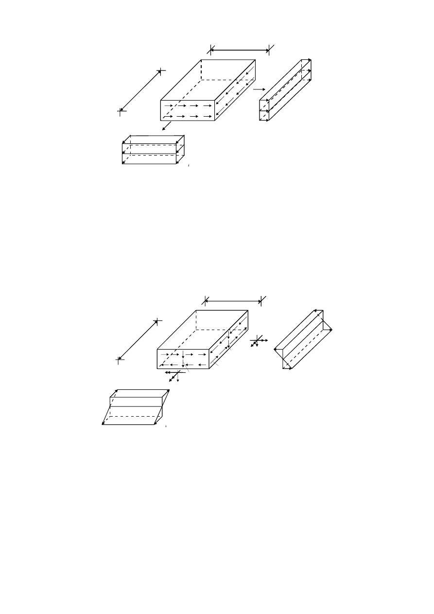
Membrane stresses in rectangular plate, see Figure 1.2:
σ
mx
is the membrane normal stress in the x-direction due to membrane normal stress resultant per unit
width n
x
;
σ
my
is the membrane normal stress in the y-direction due to membrane normal stress resultant per unit
width n
y
;
τ
mxy
is the membrane shear stress due to membrane shear stress resultant per unit width n
xy
.
BS EN 1993-1-7:2007
Licensed copy: BSI USER 06 Document Controller, Midmac Contracting Co. W.L.L, Version correct as of 26/05/2010
14:06, (c) BSI
EN 1993-1-7: 2007 (E)
7
Figure 1.2: Membrane stresses
(3)
Bending and shear stresses in rectangular plates due to bending, see Figure 1.3:
σ
bx
is the stress in the x-direction due to bending moment per unit width m
x
;
σ
by
is the stress in the y-direction due to bending moment per unit width m
y
;
τ
bxy
is the shear stress due to the twisting moment per unit width m
xy
;
τ
bxz
is the shear stress due to transverse shear forces per unit width q
x
associated with bending;
τ
byz
is the shear stress due to transverse shear forces q
y
associated with bending.
Figure 1.3: Normal and shear stresses due to bending
NOTE: In general, there are eight stress resultants in a plate at any point. The shear stresses τ
bxz
and τ
byz
due
to q
x
and q
y
are in most practical cases insignificant compared to the other components of stress, and
therefore they may normally be disregarded for the design.
(4)
Greek lower case letters:
α
aspect ratio of a plate segment (a/b);
ε
strain;
α
R
load amplification factor;
ρ
reduction factor for plate buckling;
σ
i
Normal stress in the direction i, see Figure 1.2 and Figure 1.3;
mx
y
τ
τ
my
x
d
y
d
x
σ
my
mx
y
σ
mx
n
x
n
y
q
y
m
x
y
b
x
y
τ
τ
b
x
z
b
y
z
τ
τ
b
y
x
q
x
y
x
m
d
y
d
x
σ
b
y
σ
b
x
m
y
m
x
BS EN 1993-1-7:2007
Licensed copy: BSI USER 06 Document Controller, Midmac Contracting Co. W.L.L, Version correct as of 26/05/2010
14:06, (c) BSI
EN 1993-1-7: 2007 (E)
8
τ
Shear stress, see Figure 1.2 and Figure 1.3;
ν
Poisson's ratio;
γ
M
partial factor.
(5)
Latin upper case letter:
E
Modulus of elasticity
(6)
Latin lower case letters:
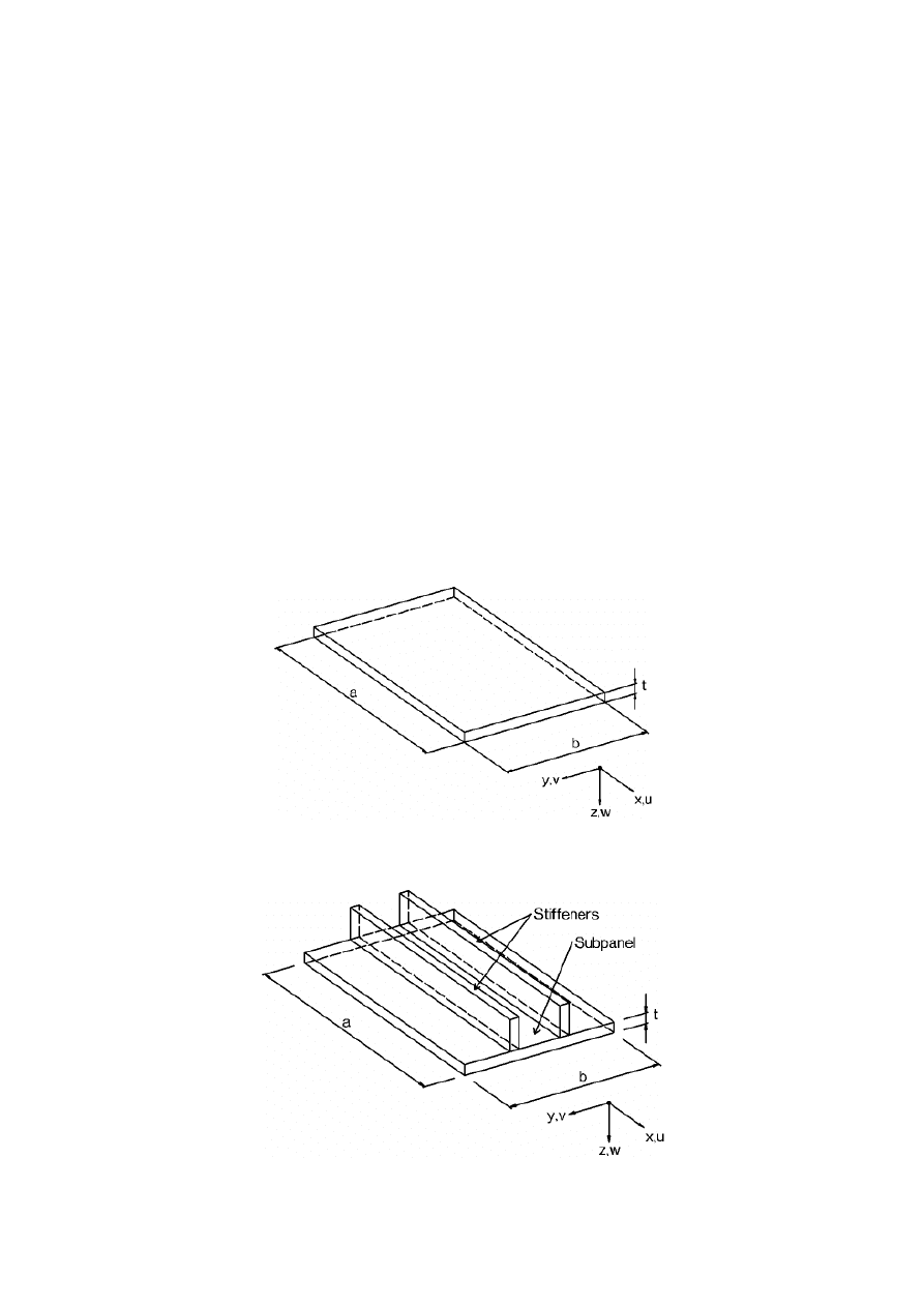
a
length of a plate segment, see Figure 1.4 and Figure 1.5;
b
width of a plate segment, see Figure 1.4 and Figure 1.5;
f
yk
yield stress or 0,2% proof stress for material with non linear stress-strain curve;
n
i
membrane normal force in the direction i [kN/m];
n
xy
membrane shear force [kN/m}
m
bending moment [kNm/m];
q
z
transverse shear force in the z direction [kN/m];
t
thickness of a plate segment, see figure 1.4 and 1.5.
NOTE: Symbols and notations which are not listed above are explained in the text where they first appear.
Figure 1.4: Dimensions and axes of unstiffened plate segments
Figure 1.5: Dimensions and axes of stiffened plate segments; stiffeners may be
open or closed stiffeners
BS EN 1993-1-7:2007
Licensed copy: BSI USER 06 Document Controller, Midmac Contracting Co. W.L.L, Version correct as of 26/05/2010
14:06, (c) BSI

EN 1993-1-7: 2007 (E)
9
2
Basis of design
2.1
Requirements
(1)P The basis of design shall be in accordance with EN 1990.
(2)P The following ultimate limit states shall be checked for a plated structure:
–
plastic collapse, see 2.2.2;
–
cyclic plasticity, see 2.2.3;
–
buckling, see 2.2.4;
–
fatigue, see 2.2.5.
(3)
The design of a plated structure should satisfy the serviceability requirements set out in the appropriate
application standards.
2.2
Principles of limit state design
2.2.1
General
(1)P The principles for ultimate limit state given in section 2 of EN 1993-1-1 and EN 1993-1-6 shall also be
applied to plated structures.
2.2.2
Plastic collapse
(1)
Plastic collapse is defined as the condition in which a part of the structure develops excessive plastic
deformations, associated with development of a plastic mechanism. The plastic collapse load is usually
derived from a mechanism based on small deflection theory.
2.2.3
Cyclic plasticity
(1)
Cyclic plasticity should be taken as the limit condition for repeated cycles of loading and unloading
produce yielding in tension or in compression or both at the same point, thus causing plastic work to be
repeatedly done on the structure. This alternative yielding may lead to local cracking by exhaustion of the
material's energy absorption capacity, and is thus a low cycle fatigue restriction. The stresses which are
associated with this limit state develop under a combination of all actions and the compatibility conditions
for the structure.
2.2.4
Buckling
(1)
Buckling should be taken as the condition in which all or parts of the structure develop large
displacements, caused by instability under compressive and/or shear stresses in the plate. It leads eventually
to inability to sustain an increase in the stress resultants.
(2) Local plate buckling, see EN 1993-1-5.
(3)
For flexural, lateral torsional and distortional stability of stiffeners, see EN 1993-1-5
2.2.5
Fatigue
(1)
Fatigue should be taken as the limit condition caused by the development and / or growth of cracks by
repeated cycles of increasing and decreasing stresses.
2.3
Actions
(1)
The characteristic values of actions should be determined from the appropriate parts of EN 1991.
BS EN 1993-1-7:2007
Licensed copy: BSI USER 06 Document Controller, Midmac Contracting Co. W.L.L, Version correct as of 26/05/2010
14:06, (c) BSI

EN 1993-1-7: 2007 (E)
10
2.4
Design assisted by testing
(1)
For design assisted by testing reference should be made to section 2.5 of EN 1993-1-1 and where
relevant, Section 9 of EN 1993-1-3.
3
Material properties
(1)
This Standard covers the design of plated structures fabricated from steel material conforming to the
product standards listed in EN 1993-1-1 and EN 1993-1-12.
(2)
The material properties of cold formed members and sheeting should be obtained from EN 1993-1-3.
(3)
The material properties of stainless steels should be obtained from EN 1993-1-4.
4
Durability
(1)
For durability see section 4 of EN 1993-1-1.
5
Structural analysis
5.1
General
(1)P The models used for calculations shall be appropriate for predicting the structural behaviour and the
limit states considered.
(2)
If the boundary conditions can be conservatively defined, i.e. restrained or unrestrained, a plated
structure may be subdivided into individual plate segments that may be analysed independently.
(3)P The overall stability of the complete structure shall be checked following the relevant parts of
EN 1993.
5.2
Stress resultants in the plate
5.2.1
General
(1)
The calculation model and basic assumptions for determining internal stresses or stress resultants
should correspond to the assumed structural response for the ultimate limit state loading.
(2)
Structural models may be simplified such that it can be shown that the simplifications used will give
conservative estimates of the effects of actions.
(3)
Elastic global analysis should generally be used for plated structures. Where fatigue is likely to occur,
plastic global analysis should not be used.
(4)
Possible deviations from the assumed directions or positions of actions should be considered.
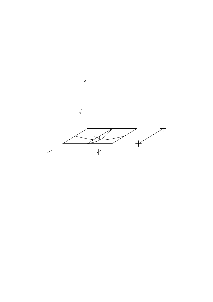
(5)
Yield line analysis may be used in the ultimate limit state when inplane compression or shear is less
than 10% of the corresponding resistance. The bending resistance in a yield line should be taken as
0
2
25
,
0
M
y
Rd
t
f
m
γ
⋅
⋅
=
5.2.2
Plate boundary conditions
(1)
Boundary conditions assumed in analyses should be appropriate to the limit states considered.
BS EN 1993-1-7:2007
Licensed copy: BSI USER 06 Document Controller, Midmac Contracting Co. W.L.L, Version correct as of 26/05/2010
14:06, (c) BSI
EN 1993-1-7: 2007 (E)
11
(2)P If a plated structure is subdivided into individual plate segments the boundary conditions assumed for
stiffeners in individual plate segments in the design calculations shall be recorded in the drawings and
project specification.
5.2.3
Design models for plated structures
5.2.3.1
General
(1)
The internal stresses of a plate segment should be determined as follows:
–
standard formulae, see 5.2.3.2;
–
global analysis, see 5.2.3.3;
–
simplified models, see 5.2.3.4.
(2)
The design methods given in (1) should take into account a linear or non linear bending theory for
plates as appropriate.
(3)
A linear bending theory is based on small-deflection assumptions and relates loads to deformations in
a proportional manner. This may be used if inplane compression or shear is less than 10% of the
corresponding resistance.
(4)
A non-linear bending theory is based on large-deflection assumptions and the effects of deformation
on equilibrium are taken into account.
(5)
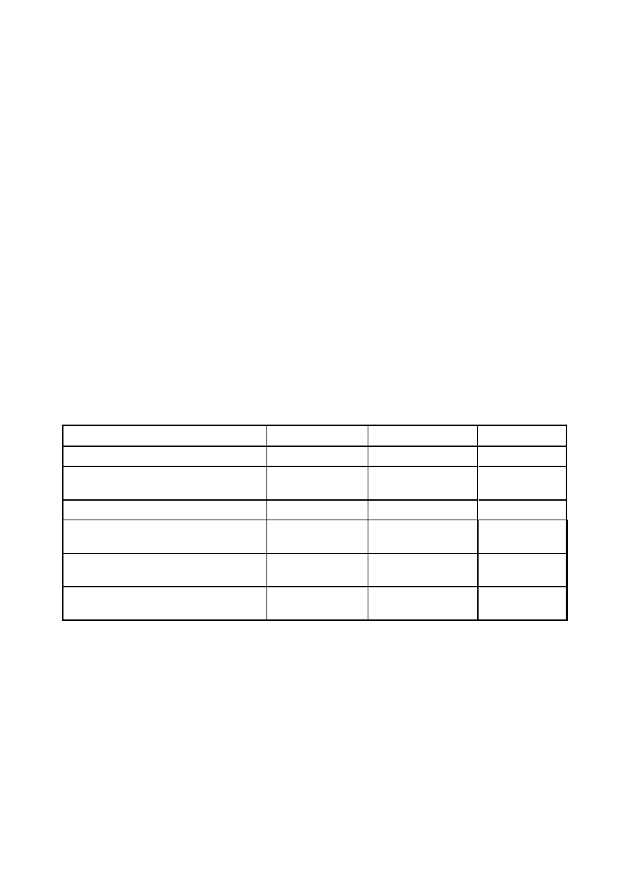
The design models given in (1) may be based on the types of analysis given in Table 5.1.
Table 5.1: Types of analysis
Type of analysis
Bending theory
Material law
Plate geometry
Linear elastic plate analysis (LA)
linear
linear
perfect
Geometrically non-linear elastic analysis
(GNA)
non-linear
linear
perfect
Materially non-linear analysis (MNA)
linear
non-linear
perfect
Geometrically and materially non-linear
analysis (GMNA)
non-linear
non-linear
perfect
Geometrically non-linear elastic analysis
with imperfections (GNIA)
non-linear
linear
imperfect
Geometrically and materially non-linear
analysis with imperfections (GMNIA)
non-linear
non-linear
imperfect
NOTE 1: A definition of the different types of analysis is given in Annex A.
NOTE 2: The type of analysis appropriate to a structure should be stated in the project specification.
NOTE 3: The use of a model with perfect geometry implies that geometrical imperfections are either not
relevant or included through other design provisions.
NOTE 4: Amplitudes for geometrical imperfections for imperfect geometries are chosen such that in
comparisons with results from tests using test specimens fabricated with tolerances according to EN 1090-2
the calculative results are reliable, therefore these amplitudes in general differ from the tolerances given in
EN 1090-2.
5.2.3.2
Use of standard formulas
(1)
For an individual plate segment of a plated structure the internal stresses may be calculated for the
relevant combination of design actions with appropriate design formulae based on the types of analysis given
in 5.2.3.1.
BS EN 1993-1-7:2007
Licensed copy: BSI USER 06 Document Controller, Midmac Contracting Co. W.L.L, Version correct as of 26/05/2010
14:06, (c) BSI

EN 1993-1-7: 2007 (E)
12
NOTE: Annex B and Annex C provide tabulated values for rectangular unstiffened plates which are
loaded transversely. For circular plates design formulas are given in EN 1993-1-6. Further design formulas
may be used, if the reliability of the design formulas is in accordance with the requirements given in
EN 1991-1.
(2)
In case of a two dimensional stress field resulting from a membrane theory analysis the equivalent
Von Mises stress σ
eq,Ed
may be determined by
n
3
+
n
n
-
n
+
n
t
1
2
d
xy,
d
y,
d
x,
2
d
y,
2
d
x,
,
E
E
E
E
E
Ed
eq
=
σ
(5.1)
(3)
In case of a two dimensional stress field resulting from an elastic plate theory the equivalent
Von Mises stress σ
eq,Ed
may be determined, as follows:
τ
σ
σ
σ
σ
σ
2
d
xy,
d
y,
d
x,
2
d
y,
2
d
x,
,
3
+
-
+
E
E
E
E
E
Ed
eq
=
(5.2)
where
4
/
t
m
t
n
=
2
d
x,
d
x,
d
x,
E
E
E
±
σ
4
/
t
m
t
n
=
2
Ed
y,
Ed
y,
Ed
y,
±
σ
4
/
t
m
t
n
=
2
Ed
xy,
Ed
xy,
Ed
xy,
±
τ
and n
x,Ed
, n
y,Ed
, n
xy,Ed
, m
x,Ed
, m
y,Ed
and m
xy,Ed
are defined in 1.4(1) and (2).
NOTE: The above expressions give a simplified conservative equivalent stress for design
5.2.3.3
Use of a global analysis: numerical analysis
(1)
If the internal stresses of a plated structure are determined by a numerical analysis which is based on a
materially linear analysis, the maximum equivalent Von Mises stress σ
eq,Ed
of the plated structure should be
calculated for the relevant combination of design actions.
(2)
The equivalent Von Mises stress σ
eq,Ed
is defined by the stress components which occurred at one point
in the plated structure.
2
2
2
,
,
,
,
,
,
+
+ 3
eq Ed
x Ed
y Ed
x Ed
y Ed
xy Ed
σ
σ
σ
σ
σ
τ
=
−
⋅
(5.3)
where σ
x,Ed
and σ
y,Ed
are positive in case of tension.
(3)
If a numerical analysis is used for the verification of buckling, the effects of imperfections should be
taken into account. These imperfections may be:
(a)
geometrical imperfections:
–
deviations from the nominal geometric shape of the plate (initial deformation, out of plane
deflections);
–
irregularities of welds (minor eccentricities);
–
deviations from nominal thickness.
(b)
material imperfections:
–
residual stresses because of rolling, pressing , welding, straightening;
–
non-homogeneities and anisotropies.
BS EN 1993-1-7:2007
Licensed copy: BSI USER 06 Document Controller, Midmac Contracting Co. W.L.L, Version correct as of 26/05/2010
14:06, (c) BSI
EN 1993-1-7: 2007 (E)
13
(4)
The geometrical and material imperfections should be taken into account by an initial equivalent
geometric imperfection of the perfect plate. The shape of the initial equivalent geometric imperfection should
be derived from the relevant buckling mode.
(5)
The amplitude of the initial equivalent geometric imperfection e
0
of a rectangular plate segment may
be derived by numerical calibrations with test results from test pieces that may be considered as
representative for fabrication from the plate buckling curve of EN 1993-1-5, as follows:
ζ
ρ
ρ
λ
ρ
)
-
1
(
)
-
(1
=
p
e
0
(5.4)
where
)
b
+
a
t (
)
a
+
ν
b
(
b
2
2
2
2
2
2
6
=
ζ
and α <
2
ρ
is the reduction factor for plate buckling as defined in 4.4 of EN 1993-1-5;
a,b
are geometric properties of the plate, see Figure 5.1;
t
is the thickness of the plate;
α is the aspect ratio a/b <
2
;
λ
p
is the relative slenderness of the plate, see EN 1993-1-5.
Figure 5.1: Initial equivalent geometric bow imperfection e
0
of a plate segment
(6)
As a conservative assumption the amplitude may be taken as e
0
= a/200 where b
≤ a.
(7)
The pattern of the equivalent geometric imperfections should, if relevant, be adapted to the
constructional detailing and to imperfections expected from fabricating or manufacturing.
(8)P In all cases the reliability of a numerical analysis shall be checked with known results from tests or
compared analysis.
5.2.3.4
Use of simplified design methods
5.2.3.4.1
General
(1)
The internal forces or stresses of a plated structure loaded by out of plane loads and in-plane loads
may be determined using a simplified design model that gives conservative estimates.
(2)
Therefore the plated structure may be subdivided into individual plate segments, which may be
stiffened or unstiffened.
5.2.3.4.2
Unstiffened plate segments
(1)
An unstiffened rectangular plate under out of plane loads may be modeled as an equivalent beam in
the direction of the dominant load transfer, if the following conditions are fulfilled:
–
the aspect ratio a/b of the plate is greater than 2;
–
the plate is subjected to out of plane distributed loads which may be either linear or vary linearly;
–
the strength, stability and stiffness of the frame or beam on which the plate segment is supported fulfil
the assumed boundary conditions of the equivalent beam.
b
a
e
0
BS EN 1993-1-7:2007
Licensed copy: BSI USER 06 Document Controller, Midmac Contracting Co. W.L.L, Version correct as of 26/05/2010
14:06, (c) BSI
EN 1993-1-7: 2007 (E)
14
(2)
The internal forces and moments of the equivalent beam should be determined using an elastic or
plastic analysis as defined in EN 1993-1-1.
(3)
If the first order deflections due to the out of plane loads is similar to the (plate) buckling mode due to
the in plane compression forces, the interaction between both phenomena need to be taken into account.
(4)
In cases where the situation as described in (3) is present the interaction formula specified in
EN 1993-1-1, section 6.3.3 may be applied to the equivalent beam.
5.2.3.4.3
Stiffened plate segments
(1)
A stiffened plate or a stiffened plate segment may be modeled as a grillage if it is regularly stiffened in
the transverse and longitudinal direction.
(2)
In determining the cross-sectional area A
i
of the cooperating plate of an individual member i of the
grillage the effects of shear lag should be taken into account by the reduction factor β according to
EN 1993-1-5.
(3)
For a member i of the grillage which is arranged in parallel to the direction of inplane compression
forces, the cross-sectional area A
i
should also be determined taking account of the effective width of the
adjacent subpanels due to plate buckling according to EN 1993-1-5.
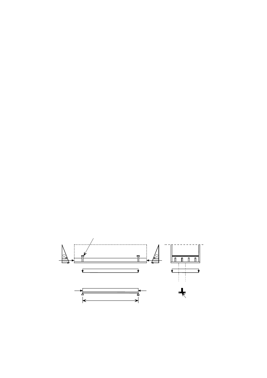
(4)
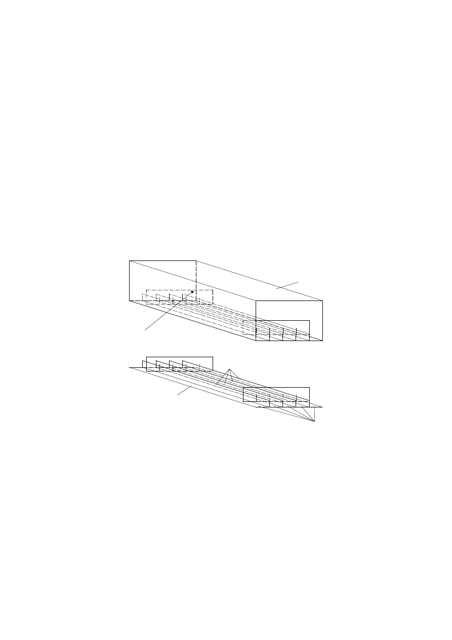
The interaction between shear lag effects and plate buckling effects, see Figure 5.2, should be
considered by the effective area A
i
from the following equation:
A
i
= [ρ
c
( A
L,eff
+ Σ ρ
pan,i
b
pan,i
t
pan,i
)] β
κ
(5.5)
where A
L,eff
is the effective area of the stiffener considering to local plate buckling of the stiffener;
ρ
c
is the reduction factor due to global plate buckling of the stiffened plate segment, as defined in
4.5.4(1) of EN 1993-1-5;
ρ
pan,i
is the reduction factor due to local plate buckling of the subpanel i, as defined in 4.4(1) of
EN 1993-1-5;
b
pan,i
is the width of the subpanel i, as defined in 4.5.1(3) of EN 1993-1-5;
t
pan,i
is the thickness of the subpanel i;
β
is the effective width factor for the effect of shear lag, see 3.2.1 of EN 1993-1-5;
κ
is the ratio defined in 3.3 of EN 1993-1-5.
Figure 5.2: Definition of the cross-section A
i
(5)
The verification of a member i of the grillage may be performed using the interaction formula in
EN 1993-1-1, section 6.3.3 taking into account the following loading conditions:
–
effects of out of plane loadings;
–
equivalent axial force in the cross section A
i
due to normal stresses in the plate;
Transverse stiffener
q
q
Ed
Ed
Ed
Ed
Ed
Ed
a
N
N
N
N
-
-
σ
σ
x,Ed
x,Ed
e
e
1
1
i
A
BS EN 1993-1-7:2007
Licensed copy: BSI USER 06 Document Controller, Midmac Contracting Co. W.L.L, Version correct as of 26/05/2010
14:06, (c) BSI

EN 1993-1-7: 2007 (E)
15
–
eccentricity e of the equivalent axial force N
Ed
with respect to the centre of gravity of the cross-
sectional area A
i
.
(6)
If the stiffeners of a plate or a plate segment are only arranged in parallel to the direction of inplane
compression forces, the stiffened plate may be modeled as an equivalent beam on elastic springs, see
EN 1993-1-5.
(7)
If the stiffeners of a stiffened plate segment are positioned in the transverse direction to the
compression forces, the interaction between the compression forces and bending moments in the unstiffened
plate segments between the stiffeners should be verified according to 5.2.3.4.2(4).
(8)
The longitudinal stiffeners should fulfill the requirements given in section 9 of EN 1993-1-5.
(9)
The transverse stiffeners should fulfill the requirements given in section 9 of EN 1993-1-5.
6
Ultimate limit state
6.1
General
(1)P All parts of a plated structure shall be so proportioned that the basic design requirements for ultimate
limit states given in section 2 are satisfied.
(2)
For the partial factor γ
M
for resistance of plated structures see the relevant application parts of
EN 1993.
(3)
For partial factor γ
M
of connections of plated structures see EN 1993-1-8.
6.2
Plastic limit
6.2.1
General
(1)
At every point in a plated structure the design stress σ
eq,Ed
should satisfy the condition:
σ
eq,Ed
≤ σ
eq,Rd
(6.1)
where σ
eq,Ed
is the largest value of Von Mises equivalent stress as defined in 5.2.3.
(2)
In an elastic design the resistance of a plate segment against plastic collapse or tensile rupture under
combined axial forces and bending is defined by the Von Mises equivalent stress σ
eq,Rd
as:
σ
eq,Rd
= f
yk
/ γ
M0
(6.2)
NOTE: For the numerical value of
γ
M0
see 1.1(2).
6.2.2
Supplementary rules for the design by global analysis
(1)
If a numerical analysis is based on materially linear analysis the resistance against plastic collapse or
tensile rupture should be checked for the requirement given in 6.2.1.
(2)
If a materially nonlinear analysis is based on a design stress-strain relationship with f
yd,
(=f
y
/γ
M0
) the
plated structure should be subject to a load arrangement F
Ed
that is taken from the design values of actions,
and the load may be incrementally increased to determine the load amplification factor α
R
of the plastic limit
state F
Rd.
(3)
The result of the numerical analysis should satisfy the condition:
F
Ed
≤ F
Rd
(6.3)
where F
Rd
= α
R
F
Ed
BS EN 1993-1-7:2007
Licensed copy: BSI USER 06 Document Controller, Midmac Contracting Co. W.L.L, Version correct as of 26/05/2010
14:06, (c) BSI

EN 1993-1-7: 2007 (E)
16
α
R
is the load amplification factor for the loads F
Ed
for reaching the ultimate limit state.
6.2.3
Supplementary rules for the design by simplified design methods
6.2.3.1
Unstiffened plates
(1)
If an unstiffened plate is designed as an equivalent beam, its cross-sectional resistance should be
checked for the combination of inplane loading and out of plane loading effects with the design rules given
in EN 1993-1-1.
6.2.3.2
Stiffened plates
(1)
If a stiffened plate segment is modeled as a grillage as described in section 5.2.3.4 the cross-section
resistance and the buckling resistance of the individual members i of the grillage should be checked for the
combination of inplane and out of plane loading effects using the interaction formula in EN 1993-1-1,
section 6.3.3.
(2)
If a stiffened plate segment is designed as an equivalent beam as described in section 5.2.3.4 the cross-
section resistance and the buckling resistance of the equivalent beam should be checked for the combination
of inplane and out of plane loading effects using the interaction formula in EN 1993-1-1, section 6.3.3.
(3)
The stress resultants or stresses of a subpanel should be verified against tensile rupture or plastic
collapse with the design rules given in 5.2.3.2, 5.2.3.3 or 5.2.3.4.
6.3
Cyclic plasticity
6.3.1
General
(1)
At every point in a plated structure the design stress range ∆σ
Ed
should satisfy the condition:
∆σ
Ed
≤ ∆σ
Rd
(6.4)
where ∆σ
Ed
is the largest value of the Von Mises equivalent stress range
τ
∆
σ
∆
σ
∆
σ
∆
σ
∆
σ
∆
2
Ed
Ed
y,
Ed
x,
2
Ed
y,
2
Ed
x,
Ed
eq,
3
+
-
+
=
at the relevant point of the plate segment due to the relevant combination of design actions.
(2)
In a materially linear design the resistance of a plate segment against cyclic plasticity / low cycle
fatigue may be verified by the Von Mises stress range limitation ∆σ
Rd.
∆σ
Rd
= 2,0 f
yk
/ γ
M0
(6.5)
NOTE: For the numerical value of
γ
M0
see 1.1(2).
6.3.2
Supplementary rules for the design by global analysis
(1)
Where a materially nonlinear computer analysis is carried out, the plate should be subject to the design
values of the actions.
(2)
The total accumulated Von Mises equivalent strain
ε
eq,Ed
at the end of the design life of the structure
should be assessed using an analysis that models all cycles of loading.
(3)
Unless a more refined analysis is carried out the total accumulated Von Mises equivalent plastic strain
ε
eq,Ed
may be determined from:
ε
eq,Ed
= m ∆
ε
eq,Ed
(6.6)
where: m
is the number of cycles in the design life;
∆
ε
eq,Ed
is the largest increment in the Von Mises plastic strain during one complete load cycle at any
point in the structure occurring after the third cycle.
BS EN 1993-1-7:2007
Licensed copy: BSI USER 06 Document Controller, Midmac Contracting Co. W.L.L, Version correct as of 26/05/2010
14:06, (c) BSI

EN 1993-1-7: 2007 (E)
17
(4)
Unless a more sophisticated low cycle fatigue assessment is undertaken, the design value of the total
accumulated Von Mises equivalent plastic strain
ε
eq,Ed
should satisfy the condition
M0
yk
eq
eq.Ed
p,
γ
ε
E
f
n
≤
(6.7)
NOTE 1: The National Annex may choose the value of n
eq
. The value n
eq
= 25 is recommended.
NOTE 2: For the numerical value of
γ
M0
see 1.1(2)
6.4
Buckling resistance
6.4.1
General
(1)
If a plate segment of a plated structure is loaded by in-plane compression or shear, its resistance to
plate buckling should be verified with the design rules given in EN 1993-1-5.
(2)
Flexural, lateral torsional or distortional stability of the stiffness should be verified according to
EN 1993-1-5, see also 5.2.3.4 (8) and (9)
(3) For the interaction between the effects of in-plane and out of plane loading, see section 5.
6.4.2
Supplementary rules for the design by global analysis.
(1)
If the plate buckling resistance for combined in plane and out of plane loading is checked by a
numerical analysis, the design actions F
Ed
should satisfy the condition:
F
Ed
≤ F
Rd
(6.8)
(2)
The plate buckling resistance F
Rd
of a plated structure is defined as:
F
Rd
= k F
Rk
/γ
M1
(6.9)
where F
Rk
is the characteristic buckling resistance of the plated structure
k
is the calibration factor, see (6).
NOTE: For the numerical value of
γ
M1
see 1.1(2).
(3)
The characteristic buckling resistance F
Rk
should be derived from a load-deformation curve which is
calculated for the relevant point of the structure taking into account the relevant combination of design
actions F
Ed
. In addition, the analysis should take into account the imperfections as described in 5.2.3.2.
(4)
The characteristic buckling resistance F
Rk
is defined by either of the two following criterion:
–
maximum load of the load-deformation-curve (limit load);
–
maximum tolerable deformation in the load deformation curve before reaching the bifurcation load or
the limit load, if relevant.
(5)
The reliability of the numerically determined critical buckling resistance should be checked:
(a)
either by calculating other plate buckling cases, for which characteristic buckling resistance values
F
Rk,known
are known, with the same basically similar imperfection assumptions. The check cases should
be similar in their buckling controlling parameters (e.g. non-dimensional plate slenderness, post
buckling behaviour, imperfection-sensitivity, material behaviour);
(b)
or by comparison of calculated values with test results F
Rk,known
.
(6)
Depending on the results of the reliability checks a calibration factor k should be evaluated from:
k
= F
Rk,known,check
/ F
Rk.check
(6.10)
BS EN 1993-1-7:2007
Licensed copy: BSI USER 06 Document Controller, Midmac Contracting Co. W.L.L, Version correct as of 26/05/2010
14:06, (c) BSI

EN 1993-1-7: 2007 (E)
18
where F
Rk,known,check
as follows from prior knowledge;
F
Rk.check
are the results of the numerical calculations.
6.4.3
Supplementary rules for the design by simplified design methods
(1)
If a stiffened plate segment is subdivided into subpanels and equivalent effective stiffeners as
described in section 5.2.3.4 the buckling resistance of the stiffened plate segment may be checked with the
design rules given in EN 1993-1-5. Lateral buckling of free stiffener-flanges may be checked according to
EN 1993-1-1, section 6.3.3.
(2)
The buckling resistance of the equivalent effective stiffener which is defined in section 5.2.3.4 of the
plate may be checked with the design rules given in EN 1993-1-1.
7
Fatigue
(1)
For plated structures the requirements for fatigue should be obtained from the relevant application
standard of EN 1993.
(2)
The fatigue assessment should be carried out according to the procedure given in EN 1993-1-9.
8
Serviceability limit state
8.1
General
(1)
The principles for serviceability limit state given in section 7 of EN 1993-1-1 should also be applied to
plated structures.
(2)
For plated structures especially the limit state criteria given in 8.2 and 8.3 should be verified.
8.2
Out of plane deflection
(1)
The limit of the out of plane deflection w should be defined as the condition in which the effective use
of a plate segment is ended.
NOTE
For limiting values of out of plane deflection w see application standard.
8.3
Excessive vibrations
(1)
Excessive vibrations should be defined as the limit condition in which either the failure of a plated
structure occurs by fatigue caused by excessive vibrations of the plate or serviceability limits apply.
NOTE: For limiting values of slenderness to prevent excessive vibrations see application standard.
BS EN 1993-1-7:2007
Licensed copy: BSI USER 06 Document Controller, Midmac Contracting Co. W.L.L, Version correct as of 26/05/2010
14:06, (c) BSI

EN 1993-1-7: 2007 (E)
19
Annex A [informative] – Types of analysis for the design of plated
structures
A.1 General
(1)
The internal stresses of stiffened and unstiffened plates may be determined with the following types of
analysis:
–
LA:
Linear elastic analysis;
–
GNA:
Geometrically nonlinear analysis;
–
MNA:
Materially nonlinear analysis;
–
GMNA: Geometrically and materially nonlinear analysis;
–
GNIA: Geometrically nonlinear analysis elastic with imperfections included;
–
GMNIA: Geometrically and materially nonlinear analysis with imperfections included.
A.2 Linear elastic plate analysis (LA)
(1)
The linear elastic analysis models the behaviour of thin plate structures on the basis of the plate
bending theory, related to the perfect geometry of the plate. The linearity of the theory results from the
assumptions of the linear elastic material law and the linear small deflection theory.
(2)
The LA analysis satisfies the equilibrium as well as the compatibility of the deflections. The stresses
and deformations vary linear with the out of plane loading.
(3)
As an example for the LA analysis the following fourth-order partial differential equation is given for
an isotropic thin plate that subject only to a out of plane load p(x,y):
4
4
4
2
4
4
2
w
w
w
p(x, y)
+ 2
+
=
D
y
y
x
x
∂
∂
∂
⋅
∂
∂ ∂
∂
(A.1)
where
)
υ
12 ( 1 -
E t
D =
2
3
A.3 Geometrically nonlinear analysis (GNA)
(1)
The geometrically nonlinear elastic analysis is based on the principles of the plate bending theory of
the perfect structure using the linear elastic material law and the nonlinear, large deflection theory.
(2)
The GNA analysis satisfies the equilibrium as well as the compatibility of the deflections under
consideration of the deformation of the structure.
(3)
The large deflection theory takes into account the interaction between flexural and membrane actions.
The deflections and stresses vary in a non linear manner with the magnitude of the out of plane pressure.
(4)
As an example for the GNA analysis the following fourth-order partial differential equation system is
given for an isotropic thin plate subjected only to a out of plane load p(x,y).
4
4
4
2
2
2
2
2
2
2
4
2
2
4
2
2
2
w
w
w
t
f
w
f
w
f
w
p(x, y)
+ 2
+
-
- 2
+
=
D
x y
x y
D
y
y
y
y
x
x
x
x
∂
∂
∂
∂
∂
∂
∂
∂
∂
⋅
∂
∂
∂ ∂ ∂ ∂
∂
∂ ∂
∂
∂
∂
(A.2a)
2
4
4
4
2
2
2
2
4
2
4
2
2
f
f
f
w
w
w
+ 2
+
= E
-
x y
y
y
y
x
x
x
∂
∂
∂
∂
∂
∂
⋅
∂
∂ ∂
∂
∂ ∂
∂
∂
(A.2b)
BS EN 1993-1-7:2007
Licensed copy: BSI USER 06 Document Controller, Midmac Contracting Co. W.L.L, Version correct as of 26/05/2010
14:06, (c) BSI

EN 1993-1-7: 2007 (E)
20
where f is the Airy´s stress function
D
=
)
-
1
(
12
t
E
2
3
υ
.
A.4 Materially nonlinear analysis (MNA)
(1)
The materially nonlinear analysis is based on the plate bending theory of the perfect structure with the
assumption of small deflections - like in A.2 -, however, it takes into account the nonlinear behaviour of the
material.
A.5 Geometrically and materially nonlinear analysis (GMNA)
(1)
The geometrically and materially nonlinear analysis is based on the plate bending theory of the perfect
structure with the assumptions of the nonlinear, large deflection theory and the nonlinear, elasto-plastic
material law.
A.6 Geometrically nonlinear analysis elastic with imperfections included (GNIA)
(1)
The geometrically nonlinear analysis with imperfections included is equivalent to the GNA analysis
defined in A.3, however, the geometrical model used the geometrically imperfect structure, for instance a
predeformation applies at the plate which is governed by the relevant buckling mode.
(2)
The GNIA analysis is used in cases of dominating compression or shear stresses in some of the plated
structures due to in-plane effects. It delivers the elastic buckling resistance of the "real" imperfect plated
structure.
A.7 Geometrically and materially nonlinear analysis with imperfections included
(GMNIA)
(1)
The geometrically and materially nonlinear analysis with imperfections included is equivalent to the
GMNA analysis defined in A.5, however, the geometrical model used the geometrically imperfect structure,
for instance a pre-deformation applies at the plate which is governed by the relevant buckling mode.
(2)
The GMNIA analysis is used in cases of dominating compression or shear stresses in a plate due to in-
plane effects. It delivers the elasto-plastic buckling resistance of the "real" imperfect structure.
BS EN 1993-1-7:2007
Licensed copy: BSI USER 06 Document Controller, Midmac Contracting Co. W.L.L, Version correct as of 26/05/2010
14:06, (c) BSI

EN 1993-1-7: 2007 (E)
21
Annex B [informative] – Internal stresses of unstiffened rectangular
plates from small deflection theory
B.1 General
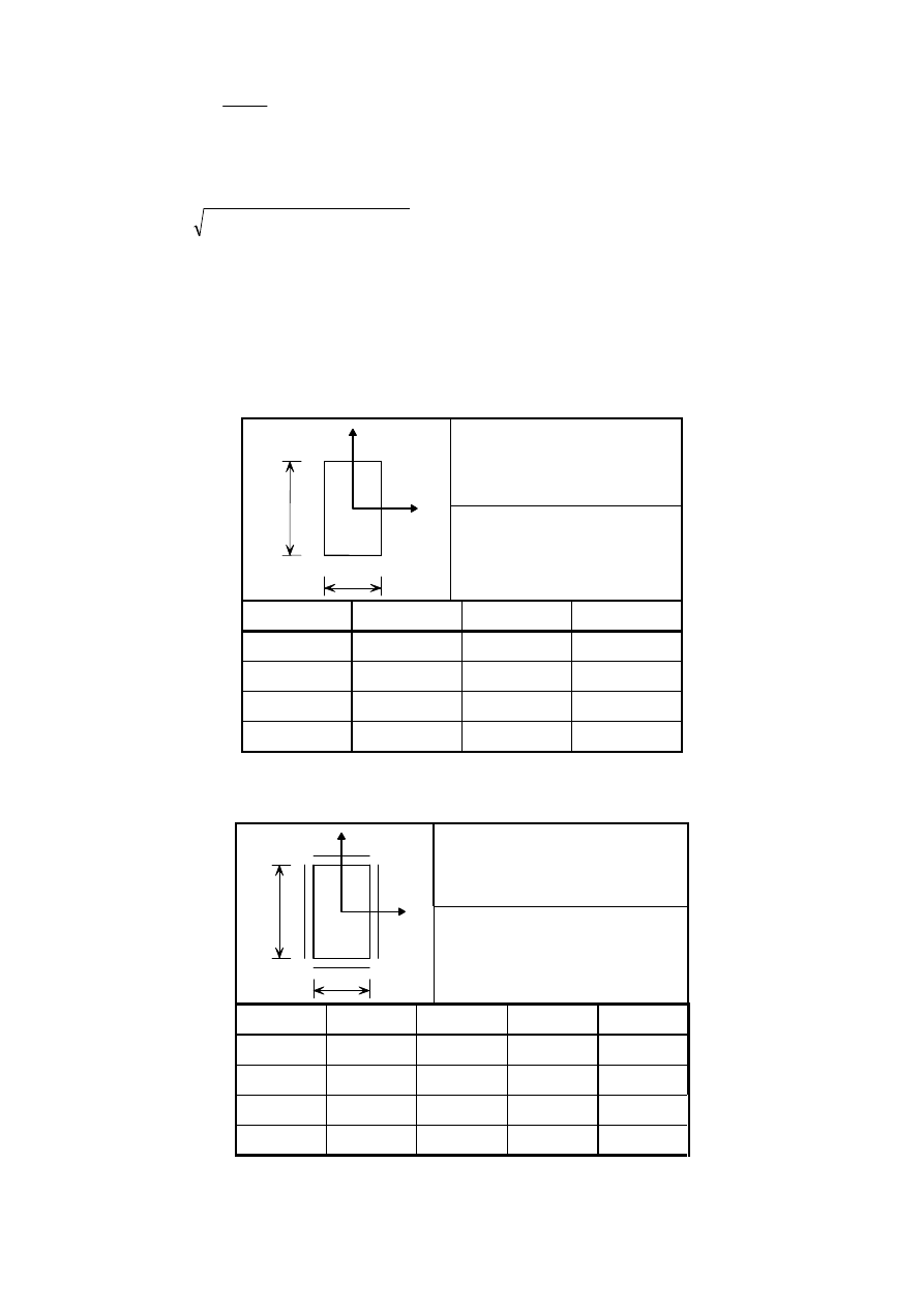
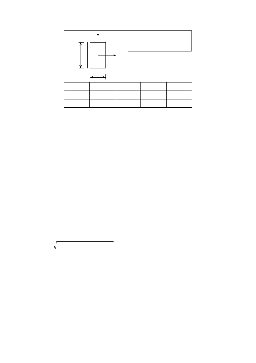
(1) This annex provides design formulae for the calculation of internal stresses of unstiffened rectangular
plates based on the small deflection theory for plates. Therefore the effects of membrane forces are not taken
into account in the design formulae given in this annex.
(2)
Design formulae are provided for the following load cases:
–
uniformly distributed loading on the entire plate, see B.3;
–
central patch loading distributed uniformly over a patch area, see B.4.
(3)
The deflection w of a plate segment and the bending stresses σ
bx
and σ
by
in a plate segment may be
calculated with the coefficients given in the tables of section B.3 and B.4. The coefficients take into account
a Poisson's ratio ν of 0,3.
B.2 Symbols
(1)
The symbols used are:
q
Ed
is the design value of the distributed load;
p
Ed
is the design value of the patch loading;
a
is the smaller side of the plate;
b
is the longer side of the plate;
t
is the thickness of the plate;
E
is the Elastic modulus;
k
w
is the coefficient for the deflection of the plate appropriate to the boundary conditions of the plate
specified in the data tables;
k
σ
bx
is the coefficient for the bending stress σ
bx
of the plate appropriate to the boundary conditions of the
plate specified in the data tables;
k
σ
by
is the coefficient for the bending stress σ
by
of the plate appropriate to the boundary conditions of the
plate specified in the data tables.
B.3 Uniformly distributed loading
B.3.1
Out of plane deflection
(1)
The deflection w of a plate segment which is loaded by uniformly distributed loading may be
calculated as follows:
3
4
Ed
w
=
E t
a
q
k
w
(B.1)
NOTE: Expression (B.1) is only valid where w is small compared with t.
B.3.2
Internal stresses
(1)
The bending stresses σ
bx
and σ
by
in a plate segment may be determined with the following equations:
t
q
k
2
2
Ed
σ
bx
Ed
bx,
a
=
σ
(B.2)
BS EN 1993-1-7:2007
Licensed copy: BSI USER 06 Document Controller, Midmac Contracting Co. W.L.L, Version correct as of 26/05/2010
14:06, (c) BSI
EN 1993-1-7: 2007 (E)
22
t
q
k
2
2
Ed
σ
by
Ed
by,
a
=
σ
(B.3)
(2)
For a plate segment the equivalent stress may be calculated with the bending stresses given in (1) as
follows:
σ
σ
σ
σ
σ
d
by,
d
bx,
2
d
by,
2
d
bx,
d
eq,
-
+
=
E
E
E
E
E
(B.4)
NOTE: The points for which the state of stress are defined in the data tables are located either on the centre
lines or on the boundaries, so that due to symmetry or the postulated boundary conditions, the bending shear
stresses τ
b
are zero.
B.3.3
Coefficients k for uniformly distributed loadings
Table B.1: Coefficients k
Loading:
Uniformly distributed loading
Boundary conditions:
All edges are rigidly supported
and rotationally free
b/a
k
w1
k
σ
bx1
k
σ
by1
1,0
0,04434
0,286
0,286
1,5
0,08438
0,486
0,299
2,0
0,11070
0,609
0,278
3,0
0,13420
0,712
0,244
Table B.2: Coefficients k
Loading:
Uniformly distributed loading
1
2
y
x
b
a
Boundary conditions:
All edges are rigidly supported
and rotationally fixed.
b/a
k
w1
k
σ
bx1
k
σ
by1
k
σ
bx2
1,0
0,01375
0,1360
0,1360
-0,308
1,5
0,02393
0,2180
0,1210
-0,454
2,0
0,02763
0,2450
0,0945
-0,498
3,0
0,02870
0,2480
0,0754
-0,505
1 2
y
x
b
a
BS EN 1993-1-7:2007
Licensed copy: BSI USER 06 Document Controller, Midmac Contracting Co. W.L.L, Version correct as of 26/05/2010
14:06, (c) BSI
EN 1993-1-7: 2007 (E)
23
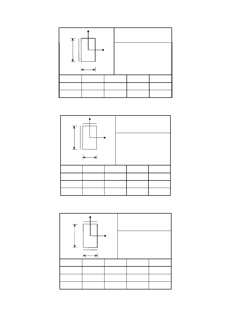
Table B.3: Coefficients k
Loading:
Uniformly distributed loading
Boundary conditions:
Three edges are rigidly
supported and rotationally free
and one edge is rigidly
supported and rotationally
fixed.
b/a
k
w1
k
σ
bx1
k
σ
by1
k
σ
bx4
1,5
0,04894
0,330
0,177
-0,639
2,0
0,05650
0,368
0,146
-0,705
Table B.4: Coefficients k
Loading:
Uniformly distributed
loading
1
y
x
b
a
4
Boundary conditions:
Two edges are rigidly
supported and rotationally
free and two edges are
rigidly supported and
rotationally fixed.
b/a
k
w1
k
σ
bx1
k
σ
by1
k
σ
bx4
1,0
0,02449
0,185
0,185
-0,375
1,.5
0,04411
0,302
0,180
-0,588
2,0
0,05421
0,355
0,152
-0,683
Table B.5: Coefficients k
Loading:
Uniformly distributed
loading
Boundary conditions:
Two opposite short edges
are clamped, the other two
edges are simply supported.
b/a
k
w1
k
σ
bx1
k
σ
by1
k
σ
by3
1,0
0,02089
0,145
0,197
-0,420
1,5
0,05803
0,348
0,274
-0,630
2,0
0,09222
0,519
0,284
-0,717
1
y
x
b
a
4
1
y
x
b
a
3
BS EN 1993-1-7:2007
Licensed copy: BSI USER 06 Document Controller, Midmac Contracting Co. W.L.L, Version correct as of 26/05/2010
14:06, (c) BSI
EN 1993-1-7: 2007 (E)
24
Table B.6: Coefficients k
Loading:
Uniformly distributed loading
1
2
y
x
b
a
Boundary conditions:
Two opposite long edges are
clamped, the other two edges
are simply supported.
b/a
k
w1
k
σ
bx1
k
σ
by1
k
σ
bx2
1,5
0,02706
0,240
0,106
-0,495
2,0
0,02852
0,250
0,0848
-0,507
B.4 Central patch loading
B.4.1
Out of plane deflection
(1)
The deflection w of a plate segment which is loaded by a central patch loading may be calculated as
follows:
3
4
Ed
w
t
=
E
a
p
k
w
(B.5)
B.4.2
Internal stresses
(1)
The bending stresses σ
bx
and σ
by
in a plate segment may be determined by the following formulas:
t
p
k
2
Ed
σ
bx
Ed
bx,
=
σ
(B.6)
t
p
k
2
Ed
σ
by
Ed
by,
=
σ
(B.7)
(2)
For a plate segment the equivalent stress may be calculated with the bending stresses given in (1) as
follows:
σ
σ
σ
σ
σ
d
by,
d
bx,
2
d
by,
2
d
bx,
d
eq,
-
+
=
E
E
E
E
E
(B.8)
BS EN 1993-1-7:2007
Licensed copy: BSI USER 06 Document Controller, Midmac Contracting Co. W.L.L, Version correct as of 26/05/2010
14:06, (c) BSI
EN 1993-1-7: 2007 (E)
25
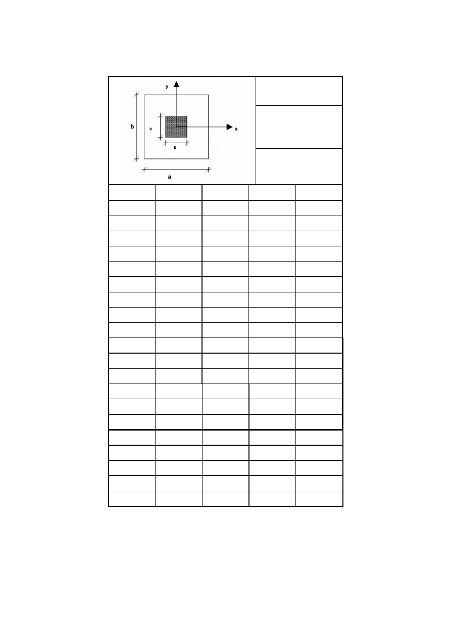
B.4.3
Coefficients k for patch loading
Table B.7: Coefficients k
Loading:
Central patch loading
Boundary conditions:
All edges are rigidly
supported and
rotationally free.
Parameters:
α = u/a
β = v/a
b/a
α
×
β
k
w1
k
σ
bx1
k
σ
by1
1
0,1
× 0,1
0,1254
1,72
1,72
0,2
× 0,2
0,1210
1,.32
1,32
0,3
× 0,3
0,1126
1,04
1,04
0,2
× 0,3
0,1167
1,20
1,12
0,2
× 0,4
0,1117
1,10
0,978
1,5
0,1
× 0,1
0,1664
1,92
1,70
0,2
× 0,2
0,1616
1,51
1,29
0,3
× 0,3
0,1528
1,22
1,01
0,2
× 0,3
0,1577
1,39
1,09
0,2
× 0,4
0,1532
1,29
0,953
2,0
0,1
× 0,1
0,1795
1,97
1,67
0,2
× 0,2
0,1746
1,56
1,26
0,3
× 0,3
0,1657
1,28
0,985
0,2
× 0,3
0,1708
1,45
1,07
0,2
× 0,4
0,1665
1,35
0,929
3,0
0,1
× 0,1
0,1840
1,99
1,66
0,2
× 0,2
0,1791
1,58
1,25
0,3
× 0,3
0,1701
1,30
0,975
0,2
× 0,3
0,1753
1,47
1,06
0,2
× 0,4
0,1711
1,37
0,918
BS EN 1993-1-7:2007
Licensed copy: BSI USER 06 Document Controller, Midmac Contracting Co. W.L.L, Version correct as of 26/05/2010
14:06, (c) BSI

EN 1993-1-7: 2007 (E)
26
Annex C [informative] – Internal stresses of unstiffened rectangular
plates from large deflection theory
C.1 General
(1)
This annex provides design formulas for the calculation of internal stresses of unstiffened rectangular
plates based on the large deflection theory for plates.
(2)
The following loading conditions are considered:
–
uniformly distributed loading on the entire plate, see C.3;
–
central patch loading distributed uniformly over the patch area, see C.4.
(3)
The bending and membrane stresses in a plate and the deflection w of a plate may be calculated with
the coefficients given in the tables of section C.3 and C.4. The coefficients take into account a Poisson's ratio
ν of 0,3.
C.2 Symbols
(1)
The symbols used are:
q
Ed
is the design value of the load uniformly distributed over the total surface;
p
Ed
is the design value of the patch loading uniformly distributed over the surface u
× v;
a
is the smaller side of the plate;
b
is the longer side of the plate;
t
is the thickness of the plate;
E
is the Elastic modulus;
FBC
flexural boundary conditions;
MBC
membrane boundary conditions;
k
w
is the coefficient for the deflection of the plate appropriate to the boundary conditions specified in the
data tables;
k
σ
bx
is the coefficient for the bending stress σ
bx
of the plate appropriate to the boundary conditions
specified in of the plate in the data tables;
k
σ
by
is the coefficient for the bending stress σ
by
of the plate appropriate to the boundary conditions specified
in the data tables;
k
σ
mx
is the coefficient for the membrane stress σ
mx
of the plate appropriate to the boundary conditions
specified in the data tables;
k
σ
my
is the coefficient for the membrane stress σ
my
of the plate appropriate to the boundary conditions
specified in the data tables.
C.3 Uniformly distributed loading on the total surface of the plate
C.3.1
Out of plane deflection
(1)
The deflection w of a plate segment which is loaded by uniformly distributed loading may be
calculated as follows:
3
4
Ed
w
Et
a
q
k
w =
(C.1)
BS EN 1993-1-7:2007
Licensed copy: BSI USER 06 Document Controller, Midmac Contracting Co. W.L.L, Version correct as of 26/05/2010
14:06, (c) BSI

EN 1993-1-7: 2007 (E)
27
C.3.2
Internal stresses
(1)
The bending stresses σ
bx
and σ
by
in a plate segment may be determined with the following equations:
t
a
q
k
=
σ
2
2
Ed
σ
bx
Ed
bx,
(C.2)
t
a
q
k
=
σ
2
2
Ed
σ
by
Ed
by,
(C.3)
(2)
The membrane stresses σ
mx
and σ
my
in a plate segment may be determined as follows:
t
a
q
k
=
σ
2
2
Ed
σ
mx
Ed
mx,
(C.4)
t
a
q
k
=
σ
2
2
Ed
σ
my
Ed
my,
(C.5)
(3)
At the loaded surface of a plate the total stresses are calculated with the bending and membrane
stresses given in (1) and (2) as follows:
σ
x,Ed
= – σ
bx,Ed
+ σ
mx,Ed
(C.6)
σ
y,Ed
= – σ
by,Ed
+ σ
my,Ed
(C.7)
(4)
At the no-loaded surface of a plate the total stresses are determined with the bending and membrane
stresses given in (1) and (2) as follows:
σ
x,Ed
= σ
bx,Ed
+ σ
mx,Ed
(C.8)
σ
y,Ed
= σ
by,Ed
+ σ
my,Ed
(C.9)
(5)
For a plate the equivalent stress σ
v,Ed
may be calculated with the stresses given in (4) as follows:
σ
σ
σ
σ
σ
d
E
y,
d
E
x,
2
d
E
y,
2
d
E
x,
d
E
eq,
-
+
=
(C.10)
NOTE: The points for which the state of stress are defined in the data tables are located either on the
centre lines or on the boundaries, so that due to symmetry or the postulated boundary conditions, membrane
shearing stresses τ
m
as well as bending shear stresses τ
b
are zero. The algebraic sum of the appropriate
bending and membrane stresses at the points considered in the data tables gives the values of maximum and
minimum surface stresses at these points.
BS EN 1993-1-7:2007
Licensed copy: BSI USER 06 Document Controller, Midmac Contracting Co. W.L.L, Version correct as of 26/05/2010
14:06, (c) BSI
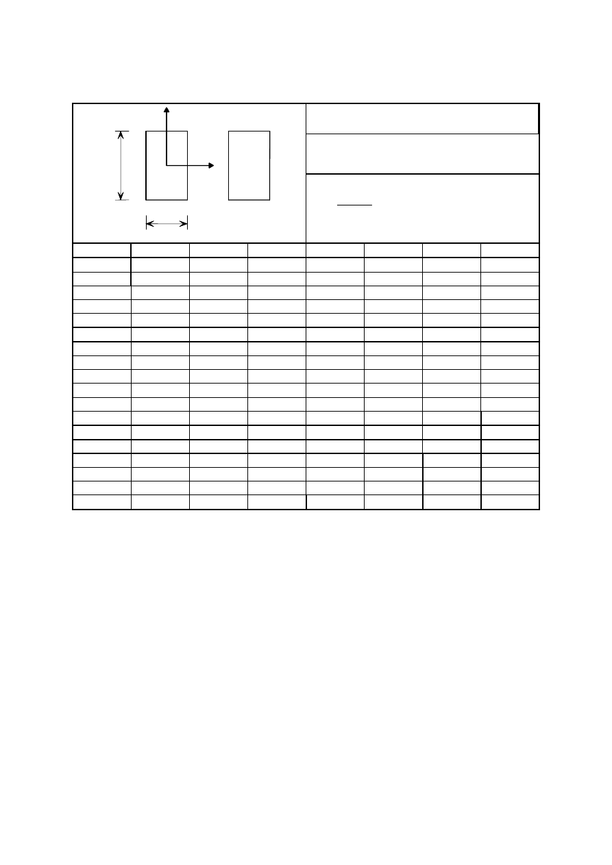
EN 1993-1-7: 2007 (E)
28
C.3.3
Coefficients k for uniformly distributed loadings
Table C.1: Coefficients k
Loading:
Uniformly distributed loading
Boundary conditions:
FBC: All edges are simply supported.
MBC: Zero direct stresses, zero shear stresses
Parameters:
Q
=
4
4
Ed
E t
a
q
b/a
Q
k
w1
k
σ
bx1
k
σ
by1
k
σ
mx1
k
σ
my1
k
σ
my2
1,0
20
0,0396
0,2431
0,2431
0,0302
0,0302
-0,0589
40
0,0334
0,1893
0,1893
0,0403
0,0403
-0,0841
120
0,0214
0,0961
0,0961
0,0411
0,0411
-0,1024
200
0,0166
0,0658
0,0658
0,0372
0,0372
-0,1004
300
0,0135
0,0480
0,0480
0,0335
0,0335
-0,0958
400
0,0116
0,0383
0,0383
0,0306
0,0306
-0,0915
1,5
20
0,0685
0,3713
0,2156
0,0243
0,0694
-0,1244
40
0,0546
0,2770
0,1546
0,0238
0,0822
-0,1492
120
0,0332
0,1448
0,0807
0,0170
0,0789
-0,1468
200
0,0257
0,1001
0,0583
0,0141
0,0715
-0,1363
300
0,0207
0,0724
0,0440
0,0126
0,0646
-0,1271
400
0,0176
0,0569
0,0359
0,0117
0,0595
-0,1205
2,0
20
0,0921
0,4909
0,2166
0,0085
0,0801
-0,1346
40
0,0746
0,3837
0,1687
0,0079
0,0984
-0,1657
120
0,0462
0,2138
0,0959
0,0073
0,0992
-0,1707
200
0,0356
0,1516
0,0695
0,0067
0,0914
-0,1610
300
0,0287
0,1121
0,0528
0,0061
0,0840
-0,1510
400
0,0245
0,0883
0,0428
0,0061
0,0781
-0,1434
1 2
y
x
FBC
MBC
b
a
BS EN 1993-1-7:2007
Licensed copy: BSI USER 06 Document Controller, Midmac Contracting Co. W.L.L, Version correct as of 26/05/2010
14:06, (c) BSI
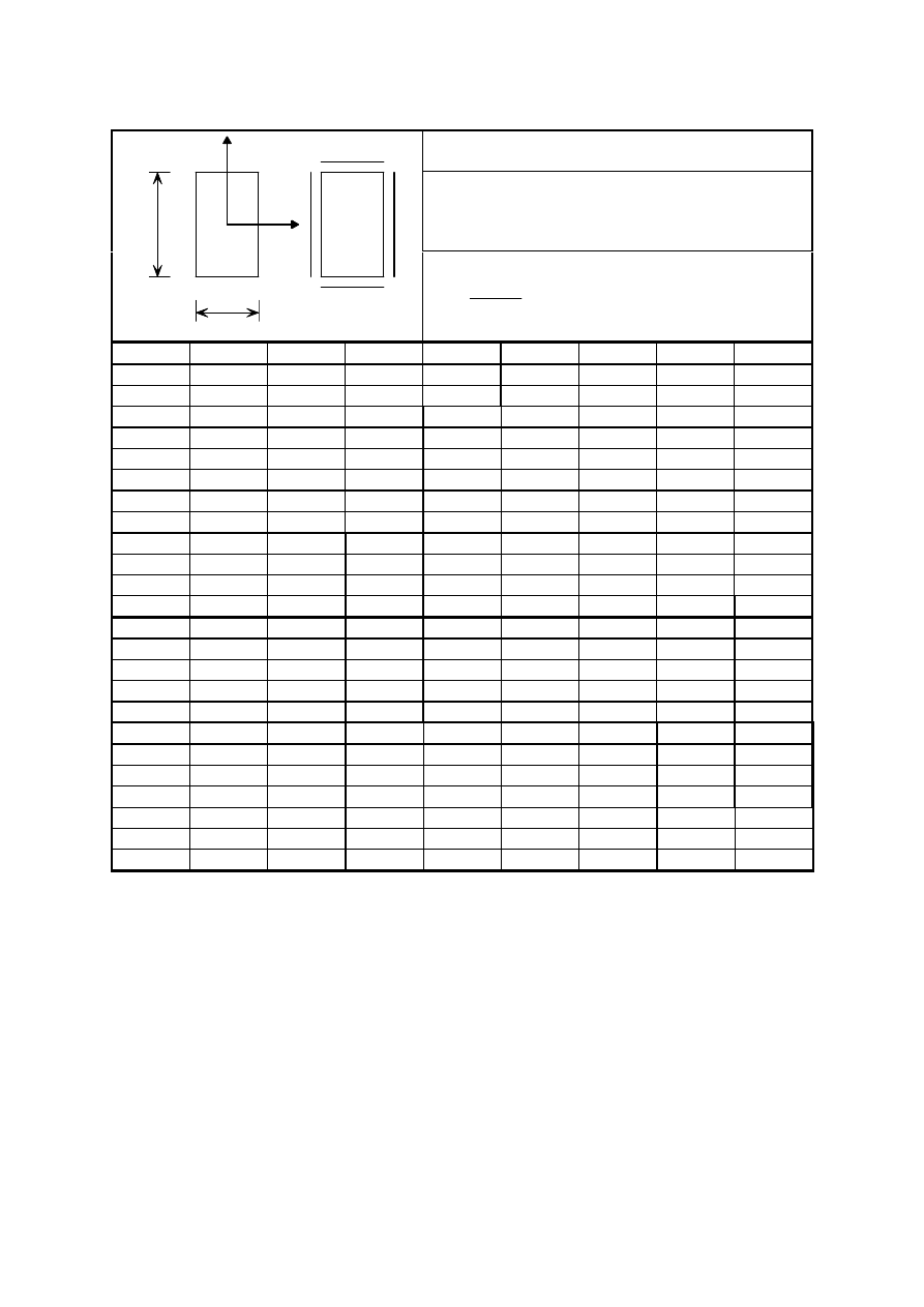
EN 1993-1-7: 2007 (E)
29
Table C.2: Coefficients k
Loading:
Uniformly distributed loading:
Boundary conditions:
FBC: All edges are simply supported.
MBC: All edges remain straight. Zero average direct
stresses, zero shear stresses
1
2
y
x
FBC
MBC
b
a
Parameters:
4
4
Ed
Et
a
q
Q =
b/a
Q
k
w1
k
σ
bx1
k
σ
by1
k
σ
mx1
k
σ
my1
k
σ
mx2
k
σ
my2
1
20
0,0369
0,2291
0,2291
0,0315
0,0315
0,0352
-0,0343
40
0,0293
0,1727
0,1727
0,0383
0,0383
0,0455
-0,0429
120
0,0170
0,0887
0,0887
0,0360
0,0360
0,0478
-0,0423
200
0,0126
0,0621
0,0621
0,0317
0,0317
0,0443
-0,0380
300
0,0099
0,0466
0,0466
0,0280
0,0280
0,0403
-0,0337
400
0,0082
0,0383
0,0383
0,0255
0,0255
0,0372
-0,0309
1,5
20
0,0554
0,3023
0,1612
0,0617
0,0287
0,0705
-0,0296
40
0,0400
0,2114
0,1002
0,0583
0,0284
0,0710
-0,0293
120
0,0214
0,1079
0,0428
0,0418
0,0224
0,0559
-0,0224
200
0,0157
0,0778
0,0296
0,0345
0,0191
0,0471
-0,0188
300
0,0122
0,0603
0,0224
0,0296
0,0167
0,0408
-0,0161
400
0,0103
0,0505
0,0188
0,0267
0,0152
0,0369
-0,0147
2
20
0,0621
0,3234
0,1109
0,0627
0,0142
0,0719
-0,0142
40
0,0438
0,2229
0,0689
0,0530
0,0120
0,0639
-0,0120
120
0,0234
0,1163
0,0336
0,0365
0,0086
0,0457
-0,0083
200
0,0172
0,0847
0,0247
0,0305
0,0075
0,0384
-0,0067
300
0,0135
0,0658
0,0195
0,0268
0,0067
0,0335
-0,0058
400
0,0113
0,0548
0,0164
0,0244
0,0064
0,0305
-0,0050
3
20
0,0686
0,3510
0,1022
0,0477
0,0020
0,0506
-0,0007
40
0,0490
0,2471
0,0725
0,0420
0,0020
0,0441
0,0000
120
0,0267
0,1317
0,0390
0,0320
0,0027
0,0335
0,0010
200
0,0196
0,0954
0,0283
0,0271
0,0044
0,0285
0,0027
300
0,0153
0,0733
0,0217
0,0242
0,0059
0,0256
0,0044
400
0,0127
0,0605
0,0178
0,0221
0,0066
0,0235
0,0051
BS EN 1993-1-7:2007
Licensed copy: BSI USER 06 Document Controller, Midmac Contracting Co. W.L.L, Version correct as of 26/05/2010
14:06, (c) BSI
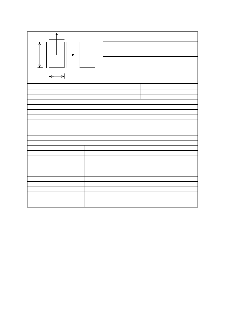
EN 1993-1-7: 2007 (E)
30
Table C.3: Coefficients k
Loading:
Uniformly distributed loading:
Boundary conditions:
FBC:
All edges are clamped.
MBC:
Zero direct stresses, zero shear stresses
Parameters:
4
4
Ed
Et
a
q
Q =
b/a
Q
k
w1
k
σ
bx1
k
σ
by1
k
σ
mx1
k
σ
my1
k
σ
bx2
k
σ
my2
1
20
0,0136
0,1336
0,1336
0,0061
0,0061
-0,3062
-0,0073
40
0,0131
0,1268
0,1268
0,0113
0,0113
-0,3006
-0,0137
120
0,0108
0,0933
0,0933
0,0212
0,0212
-0,2720
-0,0286
200
0,0092
0,0711
0,0711
0,0233
0,0233
-0,2486
-0,0347
300
0,0078
0,0547
0,0547
0,0233
0,0233
-0,2273
-0,0383
400
0,0069
0,0446
0,0446
0,0226
0,0226
-0,2113
-0,0399
1,5
20
0,0234
0,2117
0,1162
0,0061
0,0133
-0,4472
-0,0181
40
0,0222
0,1964
0,1050
0,0098
0,0234
-0,4299
-0,0322
120
0,0173
0,1406
0,0696
0,0124
0,0385
-0,3591
-0,0559
200
0,0144
0,1103
0,0537
0,0116
0,0415
-0,3160
-0,0620
300
0,0122
0,0879
0,0430
0,0105
0,0416
-0,2815
-0,0636
400
0,0107
0,0737
0,0364
0,0098
0,0409
-0,2583
-0,0635
2
20
0,0273
0,2418
0,0932
0,0010
0,0108
-0,4935
-0,0150
40
0,0265
0,2330
0,0897
0,0017
0,0198
-0,4816
-0,0277
120
0,0223
0,1901
0,0740
0,0032
0,0392
-0,4223
-0,0551
200
0,0192
0,1578
0,0621
0,0039
0,0456
-0,3780
-0,0647
300
0,0165
0,1306
0,0518
0,0042
0,0483
-0,3396
-0,0690
400
0,0147
0,1120
0,0446
0,0044
0,0487
-0,3132
-0,0702
3
20
0,0288
0,2492
0,0767
-0,0015
0,0027
-0,5065
-0,0033
40
0,0290
0,2517
0,0795
-0,0022
0,0066
-0,5095
-0,0084
120
0,0281
0,2440
0,0812
-0,0010
0,0247
-0,4984
-0,0331
200
0,0260
0,2230
0,0750
0,0000
0,0368
-0,4702
-0,0497
250
0,0247
0,2096
0,0707
0,0002
0,0415
-0,4520
-0,0564
1 2
y
x
FBC
MBC
b
a
BS EN 1993-1-7:2007
Licensed copy: BSI USER 06 Document Controller, Midmac Contracting Co. W.L.L, Version correct as of 26/05/2010
14:06, (c) BSI
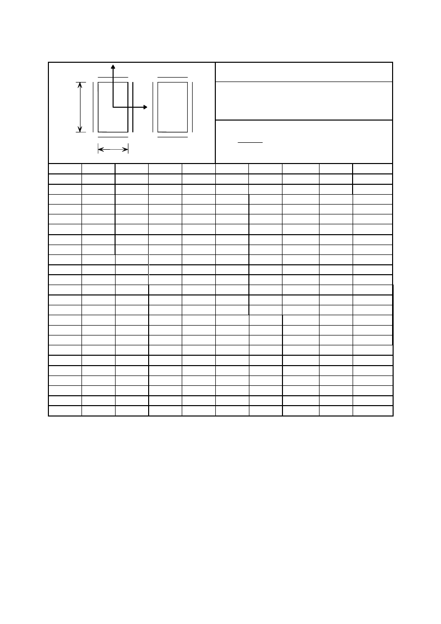
EN 1993-1-7: 2007 (E)
31
Table C.4: Coefficients k
Loading:
Uniformly distributed loading:
Boundary conditions:
FBC: All edges are clamped.
MBC: All edges remain straight. Zero average
direct stresses, zero shear stresses
Parameters:
4
4
Ed
E t
a
q
Q =
b/a
Q
k
w1
k
σ
bx1
k
σ
by1
k
σ
mx1
k
σ
my1
k
σ
bx2
k
σ
mx2
k
σ
my2
1
20
0,0136
0,1333
0,1333
0,0065
0,0065
-0,3058
0,0031
-0,0055
40
0,0130
0,1258
0,1258
0,0118
0,0118
-0,3000
0,0059
-0,0103
120
0,0105
0,0908
0,0908
0,0216
0,0216
-0,2704
0,0123
-0,0202
200
0,0087
0,0688
0,0688
0,0234
0,0234
-0,2473
0,0151
-0,0233
300
0,0073
0,0528
0,0528
0,0231
0,0231
-0,2267
0,0169
-0,0244
400
0,0063
0,0430
0,0430
0,0223
0,0223
-0,2119
0,0176
-0,0246
1,5
20
0,0230
0,2064
0,1125
0,0137
0,0097
-0,4431
0,0118
-0,0082
40
0,0210
0,1833
0,0957
0,0218
0,0155
-0,4195
0,0200
-0,0133
120
0,0149
0,1175
0,0532
0,0275
0,0202
-0,3441
0,0295
-0,0185
200
0,0118
0,0876
0,0369
0,0259
0,0195
-0,3028
0,0304
-0,0182
300
0,0096
0,0678
0,0275
0,0238
0,0180
-0,2710
0,0300
-0,0173
400
0,0083
0,0562
0,0221
0,0220
0,0168
-0,2492
0,0291
-0,0163
2
20
0,0262
0,2288
0,0853
0,0140
0,0060
-0,4811
0,0149
-0,0052
40
0,0234
0,1994
0,0701
0,0206
0,0086
-0,4492
0,0234
-0,0077
120
0,0162
0,1276
0,0404
0,0238
0,0094
-0,3611
0,0299
-0,0086
200
0,0129
0,0963
0,0296
0,0223
0,0085
-0,3162
0,0289
-0,0079
300
0,0105
0,0752
0,0230
0,0208
0,0077
-0,2824
0,0274
-0,0072
400
0,0090
0,0627
0,0190
0,0196
0,0071
-0,2600
0,0259
-0,0066
3
20
0,0272
0,2331
0,0700
0,0102
0,0010
-0,4878
0,0111
-0,0008
40
0,0247
0,2071
0,0615
0,0149
0,0011
-0,4575
0,0167
-0,0009
120
0,0177
0,1396
0,0413
0,0186
0,0009
-0,3727
0,0202
-0,0005
200
0,0143
0,1074
0,0319
0,0184
0,0009
-0,3272
0,0197
-0,0003
300
0,0117
0,0848
0,0251
0,0176
0,0008
-0,2924
0,0192
-0,0002
400
0,0101
0,0709
0,0210
0,0169
0,0008
-0,2687
0,0182
0,0000
1 2
y
x
FBC
MBC
b
a
BS EN 1993-1-7:2007
Licensed copy: BSI USER 06 Document Controller, Midmac Contracting Co. W.L.L, Version correct as of 26/05/2010
14:06, (c) BSI

EN 1993-1-7: 2007 (E)
32
C.4 Central patch loading
C.4.1
General
(1)
The deflection w and the stresses should be determined with the formulas provided for a plate which is
loaded by a central patch loading p
Ed
, distributed over an area of u long and v wide:
3
4
Ed
w
Et
a
p
k
w
=
(C.11)
C.4.2
Internal stresses
(1)
The bending stresses σ
bx
and σ
by
in a plate segment may be determined with the following equations:
2
2
Ed
bx
σ
Ed
bx,
t
a
p
k
=
σ
(C.12)
2
2
Ed
by
σ
Ed
by,
t
a
p
k
=
σ
(C.13)
(2)
The membrane stresses σ
mx
and σ
my
in a plate segment may be determined as follows:
2
2
Ed
mx
σ
Ed
mx,
t
a
p
k
=
σ
(C.14)
2
2
Ed
my
σ
Ed
my,
t
a
p
k
=
σ
(C.15)
(3)
At the loaded surface of a plate the total stresses are calculated with the bending and membrane
stresses given in (1) and (2) as follows:
σ
x,Ed
= - σ
bx,Ed
+ σ
mx,Ed
(C.16)
σ
y,ed
= - σ
by,Ed
+ σ
my,Ed
(C.17)
(4)
At the no-loaded surface of a plate the total stresses are determined with the bending and membrane
stresses given in (1) and (2) as follows:
σ
x,Ed
= σ
bx,Ed
+ σ
mx,Ed
(C.18)
σ
y,Ed
= σ
by,Ed
+ σ
my,Ed
(C.19)
(5)
For a plate the equivalent stress σ
v,Ed
may be calculated with the stresses given in (4) as follows:
σ
σ
σ
σ
σ
d
y,
d
x,
2
d
y,
2
d
x,
d
eq,
-
+
=
E
E
E
E
E
(C.20)
NOTE: The points for which the state of stress are defined in the data tables are located either on the
centre lines or on the boundaries, so that due to symmetry or the postulated boundary conditions, membrane
shearing stresses τ
m
as well as bending shear stresses τ
b
are zero. The algebraic sum of the appropriate
bending and membrane stresses at the points considered in the data tables gives the values of maximum and
minimum surface stresses at these points.
BS EN 1993-1-7:2007
Licensed copy: BSI USER 06 Document Controller, Midmac Contracting Co. W.L.L, Version correct as of 26/05/2010
14:06, (c) BSI
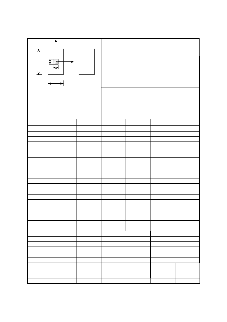
EN 1993-1-7: 2007 (E)
33
C.4.3
Coefficients k for patch loading
Table C.5: Coefficients k
Loading:
Central patch loading
Boundary conditions:
FBC: All edges are rigidly supported and rotationally
free.
MBC: Zero direct stresses, zero shear stresses
1
2
y
x
FBC
MBC
a
b
u
v
Parameters:
α = u/a; β = v/a
4
4
Et
a
p
P
Ed
=
b/a
= 1
α
×
β
p
k
w1
k
σ
bx1
k
σ
by1
k
σ
mx1
k
σ
my1
0,1
× 0,1
10
0,1021
1,4586
1,4586
0,1548
0,1548
20
0,0808
1,2143
1,2143
0,1926
0,1926
60
0,0485
0,8273
0,8273
0,2047
0,2047
100
0,0372
0,6742
0,6742
0,1978
0,1978
150
0,0298
0,5693
0,5693
0,1892
0,1892
200
0,0255
0,5005
0,5005
0,1823
0,1823
0,2
× 0,2
10
0,0998
1,0850
1,0850
0,1399
0,1399
20
0,0795
0,8593
0,8593
0,1729
0,1729
60
0,0478
0,5108
0,5108
0,1756
0,1756
100
0,0364
0,3881
0,3881
0,1624
0,1624
150
0,0293
0,3089
0,3089
0,1505
0,1505
200
0,0249
0,2614
0,2614
0,1412
0,1412
0,3
× 0,3
10
0,0945
0,8507
0,8507
0,1144
0,1144
20
0,0759
0,6614
0,6614
0,1425
0,1425
60
0,0459
0,3702
0,3702
0,1425
0,1425
100
0,0351
0,2704
0,2704
0,1300
0,1300
150
0,0282
0,2101
0,2101
0,1186
0,1186
200
0,0240
0,1747
0,1747
0,1102
0,1102
0,2
× 0,3
10
0,0971
0,9888
0,9128
0,1224
0,1288
20
0,0776
0,7800
0,7101
0,1512
0,1602
60
0,0468
0,4596
0,4021
0,1488
0,1624
100
0,0358
0,3468
0,2957
0,1368
0,1512
150
0,0287
0,2760
0,2307
0,1248
0,1389
200
0,0245
0,2340
0,1926
0,1152
0,1310
0,2
× 0,4
10
0,0939
0,9119
0,7961
0,1078
0,1183
20
0,0755
0,7216
0,6142
0,1320
0,1487
60
0,0457
0,4235
0,3355
0,1287
0,1516
100
0,0350
0,3201
0,2435
0,1166
0,1408
150
0,0280
0,2541
0,1868
0,1045
0,1301
200
0,0239
0,2156
0,1545
0,0968
0,1213
BS EN 1993-1-7:2007
Licensed copy: BSI USER 06 Document Controller, Midmac Contracting Co. W.L.L, Version correct as of 26/05/2010
14:06, (c) BSI
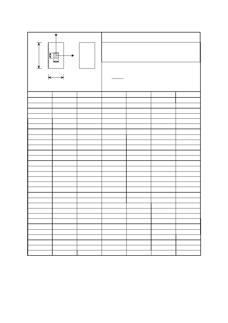
EN 1993-1-7: 2007 (E)
34
Table C.6: Coefficients k
Loading:
Central patch loading
Boundary conditions:
FBC: All edges are rigidly supported and rotationally
free.
MBC: Zero direct stresses, zero shear stresses
1
2
y
x
FBC
MBC
a
b
u
v
Parameters:
α = u/a; β = v/a
4
4
Et
a
p
P
Ed
=
b/a = 1,5
α
×
β
p
k
w1
k
σ
bx1
k
σ
by1
k
σ
mx1
k
σ
my1
0,1
× 0,1
10
0,1303
1,5782
1,3855
0,1517
0,1921
20
0,1018
1,3056
1,1373
0,1786
0,2295
60
0,0612
0,8986
0,7701
0,1824
0,2380
100
0,0469
0,7411
0,6273
0,1747
0,2295
150
0,0378
0,6298
0,5287
0,1670
0,2193
200
0,0323
0,5568
0,4641
0,1594
0,2125
0,2
× 0,2
10
0,1281
1,1974
1,0049
0,1344
0,1780
20
0,1007
0,9453
0,7766
0,1555
0,2116
60
0,0605
0,5783
0,4554
0,1465
0,2103
100
0,0462
0,4485
0,3457
0,1329
0,1974
150
0,0372
0,3624
0,2748
0,1208
0,1845
200
0,0317
0,3111
0,2322
0,1133
0,1742
0,3
× 0,3
10
0,1229
0,9589
0,7737
0,1074
0,1525
20
0,0972
0,7405
0,5828
0,1232
0,1818
60
0,0585
0,4282
0,3161
0,1110
0,1788
100
0,0449
0,3221
0,2353
0,0988
0,1667
150
0,0361
0,2550
0,1828
0,0878
0,1535
200
0,0309
0,2147
0,1525
0,0805
0,1444
0,2
× 0,3
10
0,1260
1,1037
0,8360
0,1154
0,1657
20
0,0994
0,8688
0,6322
0,1321
0,1984
60
0,0598
0,5296
0,3553
0,1168
0,1973
100
0,0459
0,4114
0,2649
0,1043
0,1853
150
0,0369
0,3336
0,2082
0,0931
0,1722
200
0,0314
0,2877
0,1755
0,0848
0,1624
0,2
× 0,4
10
0,1235
1,0294
0,7271
0,0993
0,1563
20
0,0977
0,8101
0,5432
0,1109
0,1877
60
0,0590
0,4954
0,2983
0,0955
0,1877
100
0,0453
0,3857
0,2220
0,0826
0,1754
150
0,0365
0,3148
0,1744
0,0722
0,1630
200
0,0311
0,2722
0,1468
0,0658
0,1544
BS EN 1993-1-7:2007
Licensed copy: BSI USER 06 Document Controller, Midmac Contracting Co. W.L.L, Version correct as of 26/05/2010
14:06, (c) BSI
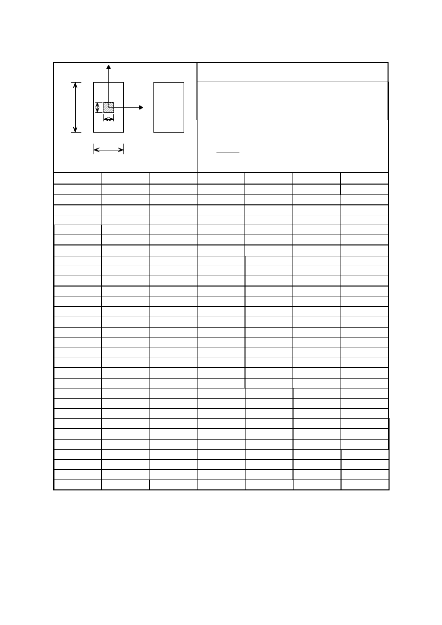
EN 1993-1-7: 2007 (E)
35
Table C.7: Coefficients k
Loading:
Central patch loading
Boundary conditions:
FBC: All edges are rigidly supported and rotationally
free.
MBC: Zero direct stresses, zero shear stresses
1
2
y
x
FBC
MBC
a
b
u
v
Parameters:
α = u/a; β = v/a
4
4
Et
a
p
P
Ed
=
b/a
= 2
α
×
β
p
k
w1
k
σ
bx1
k
σ
by1
k
σ
mx1
k
σ
my1
0,1
× 0,1
10
0,1438
1,6351
1,3560
0,1517
0,1904
20
0,1154
1,3692
1,1106
0,1773
0,2288
60
0,0725
0,9633
0,7498
0,1753
0,2438
100
0,0564
0,7979
0,6112
0,1675
0,2355
150
0,0456
0,6797
0,5127
0,1596
0,2271
200
0,0390
0,6028
0,4492
0,1517
0,2188
0,2
× 0,2
10
0,1414
1,2542
0,9752
0,1326
0,1751
20
0,1138
1,0078
0,7510
0,1513
0,2104
60
0,0716
0,6427
0,4410
0,1373
0,2167
100
0,0555
0,5054
0,3339
0,1232
0,2054
150
0,0449
0,4134
0,2646
0,1108
0,1928
200
0,0384
0,3572
0,2230
0,1030
0,1827
0,3
× 0,3
10
0,1362
1,0227
0,7506
0,1062
0,1517
20
0,1104
0,8090
0,5615
0,1190
0,1822
60
0,0698
0,4941
0,3093
0,1024
0,1862
100
0,0542
0,3789
0,2275
0,0883
0,1753
150
0,0421
0,3046
0,1783
0,0794
0,1645
200
0,0374
0,2586
0,1487
0,0717
0,1546
0,2
× 0,3
10
0,1395
1,1702
0,8164
0,1146
0,1231
20
0,1129
0,9396
0,6153
0,1262
0,1990
60
0,0712
0,6003
0,3488
0,1088
0,2044
100
0,0553
0,4742
0,2611
0,0943
0,1947
150
0,0447
0,3901
0,2065
0,0841
0,1830
200
0,0383
0,3379
0,1744
0,0754
0,1733
0,2
× 0,4
10
0,1375
1,0976
0,7051
0,0959
0,1551
20
0,1117
0,8829
0,5267
0,1053
0,1886
60
0,0706
0,5670
0,2945
0,0851
0,1942
100
0,0549
0,4496
0,2220
0,0729
0,1849
150
0,0445
0,3713
0,1765
0,0635
0,1737
200
0,0381
0,3227
0,1496
0,0554
0,1644
BS EN 1993-1-7:2007
Licensed copy: BSI USER 06 Document Controller, Midmac Contracting Co. W.L.L, Version correct as of 26/05/2010
14:06, (c) BSI
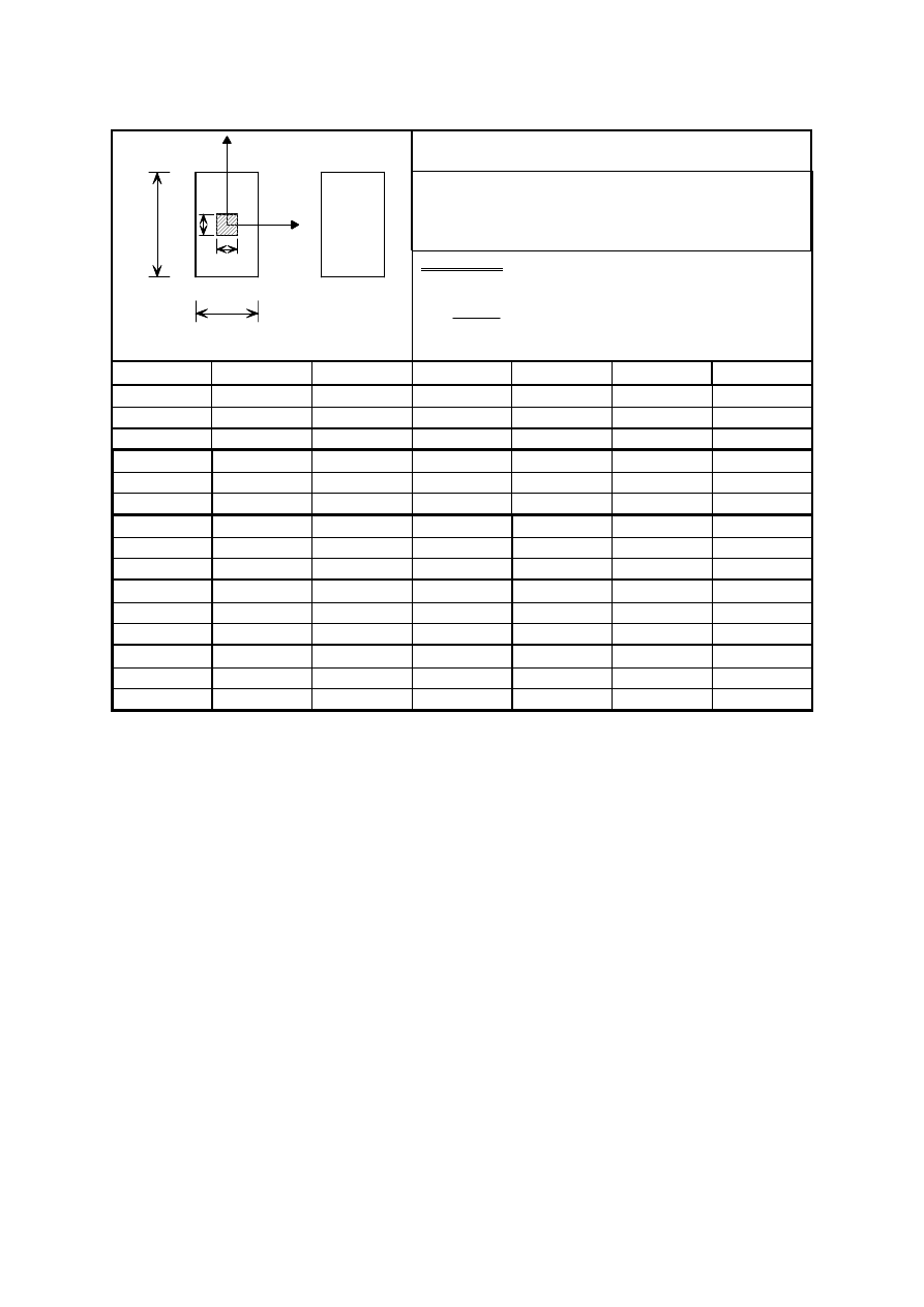
EN 1993-1-7: 2007 (E)
36
Table C.8: Coefficients k
Loading:
Central patch loading
Boundary conditions:
FBC: All edges are rigidly supported and rotationally
free.
MBC: Zero direct stresses, zero shear stresses
1
2
y
x
FBC
MBC
a
b
u
v
Parameters:
α= u/a; β = v/a
4
4
Et
a
p
P
Ed
=
b/a
= 2.5
α
×
β
p
k
w1
k
σ
bx1
k
σ
by1
k
σ
mx1
k
σ
my1
0,1
× 0,1
10
0,1496
1,6636
1,3463
0,1552
0,1826
20
0,1235
1,4109
1,1006
0,1811
0,2175
60
0,0861
1,0428
0,7453
0,1811
0,2374
0,2
× 0,2
10
0,1470
1,2814
0,9650
0,1359
0,1688
20
0,1218
1,0491
0,7400
0,1548
0,2000
60
0,0849
0,7205
0,4363
0,1390
0,2088
0,3
× 0,3
10
0,1419
1,0504
0,7410
0,1092
0,1443
20
0,1182
0,8489
0,5519
0,1222
0,1726
60
0,0827
0,5681
0,3052
0,1014
0,1775
0,2
× 0,3
10
0,1455
1,1981
0,8056
0,1161
0,1579
20
0,1210
0,9820
0,6053
0,1294
0,1876
60
0,0847
0,6806
0,3487
0,1088
0,1982
0,2
× 0,4
10
0,1434
0,1126
0,6949
0,0986
0,1469
20
0,1199
0,9261
0,5168
0,1069
0,1763
60
0,0844
0,6480
0,2993
0,0849
0,1873
BS EN 1993-1-7:2007
Licensed copy: BSI USER 06 Document Controller, Midmac Contracting Co. W.L.L, Version correct as of 26/05/2010
14:06, (c) BSI

blank
Licensed copy: BSI USER 06 Document Controller, Midmac Contracting Co. W.L.L, Version correct as of 26/05/2010
14:06, (c) BSI

BSI Group
Headquarters 389
Chiswick High Road,
London, W4 4AL, UK
Tel +44 (0)20 8996 9001
Fax +44 (0)20 8996 7001
www.bsigroup.com/
standards
BSI - British Standards Institution
BSI is the independent national body responsible for preparing British
Standards. It presents the UK view on standards in Europe and at the
international level. It is incorporated by Royal Charter.
Revisions
British Standards are updated by amendment or revision. Users of British
Standards should make sure that they possess the latest amendments or
editions.
It is the constant aim of BSI to improve the quality of our products and services.
We would be grateful if anyone finding an inaccuracy or ambiguity while using
this British Standard would inform the Secretary of the technical committee
responsible, the identity of which can be found on the inside front cover. Tel:
+44 (0)20 8996 9000. Fax: +44 (0)20 8996 7400.
BSI offers members an individual updating service called PLUS which ensures
that subscribers automatically receive the latest editions of standards.
Buying standards
Orders for all BSI, international and foreign standards publications should be
addressed to Customer Services. Tel: +44 (0)20 8996 9001. Fax: +44 (0)20 8996
7001 Email: orders@bsigroup.com You may also buy directly using a debit/credit
card from the BSI Shop on the Website http://www.bsigroup.com/shop
In response to orders for international standards, it is BSI policy to supply the
BSI implementation of those that have been published as British Standards,
unless otherwise requested.
Information on standards
BSI provides a wide range of information on national, European and
international standards through its Library and its Technical Help to Exporters
Service. Various BSI electronic information services are also available which
give details on all its products and services. Contact Information Centre. Tel:
+44 (0)20 8996 7111 Fax: +44 (0)20 8996 7048 Email: info@bsigroup.com
Subscribing members of BSI are kept up to date with standards developments
and receive substantial discounts on the purchase price of standards. For details
of these and other benefits contact Membership Administration. Tel: +44 (0)20
8996 7002 Fax: +44 (0)20 8996 7001 Email: membership@bsigroup.com
Information regarding online access to British Standards via British Standards
Online can be found at http://www.bsigroup.com/BSOL
Further information about BSI is available on the BSI website at http://
www.bsigroup.com
Copyright
Copyright subsists in all BSI publications. BSI also holds the copyright, in the
UK, of the publications of the international standardization bodies. Except as
permitted under the Copyright, Designs and Patents Act 1988 no extract may
be reproduced, stored in a retrieval system or transmitted in any form or by any
means – electronic, photocopying, recording or otherwise – without prior written
permission from BSI.
This does not preclude the free use, in the course of implementing the standard,
of necessary details such as symbols, and size, type or grade designations. If
these details are to be used for any other purpose than implementation then the
prior written permission of BSI must be obtained.
Details and advice can be obtained from the Copyright and Licensing Manager.
Tel: +44 (0)20 8996 7070 Email: copyright@bsigroup.com
BS EN
1993-1-7:2007
Licensed copy: BSI USER 06 Document Controller, Midmac Contracting Co. W.L.L, Version correct as of 26/05/2010
14:06, (c) BSI
Wyszukiwarka
Podobne podstrony:
Eurocode 3 Part 1 5 2009 Design of Steel Structures Plated Structural Elements
Eurocode 3 Part 1 4 2006 Design of Steel Structures General rules Supplementary Rules for Stainl
Eurocode 3 Part 1 9 2005 Design of Steel Structures Fatigue
Eurocode 3 Part 3 2 2006 Design of Steel Structures Towers, Masts and Chimneys Chimneys
Eurocode 2 Part 3 2006 Design of concrete structures Liquid retaining and containing structures
Eurocode 5 EN 1995 1 1 Design Of Timber Structures Part 1 1 General Rules
Eurocode 5 EN 1995 1 1 Design Of Timber Structures Part 1 1 General Rules
Eurocode 3 Part 2 2006 UK NA Design of steel structures Steel bridges
Eurocode 3 Part 1 9 2005 UK NA Design of Steel Structures Fatigue
Eurocode 3 Part 1 12 2007 UK NA Design of Steel Structures Additional Rules for the Extension of
Eurocode 3 Part 1 3 2006 UK NA Design of steel structures General rules Supplementary rules for
Eurocode 3 Part 1 11 2006 Design of Steel Structures Design of Structures With Tension Components
Eurocode 3 Part 1 11 2005 UK NA Design of Steel Structures Design of Structures with Tension Com
Eurocode 3 Part 1 2 2005 UK NA Design of steel structures General rules Structural fire design
Eurocode 3 Part 1 12 2007 Design of Steel Structures Additional Rules for the Extension of EN 199
Eurocode 2 Design of concrete structures Part 2
Eurocode 2 Design of concrete structures Part 1 3
Eurocode 6 Part 1 2 1996 2005 Design of Masonry Structures General Rules Structural Fire Design
Eurocode 6 Part 2 1996 2006 Design of Masonry Structures Design Considerations, Selection of Mat
więcej podobnych podstron