
BRITISH STANDARD
BS EN
1993-1-11:2006
Eurocode 3 — Design of
steel structures —
Part 1-11: Design of structures with
tension components
ICS 91.010.30; 91.080.10; 93.040
12&23<,1*:,7+287%6,3(50,66,21(;&(37$63(50,77('%<&23<5,*+7/$:
Incorporating
corrigendum
April 2009
Licensed copy: BSI USER 06 Document Controller, Midmac Contracting Co. W.L.L, Version correct as of 05/06/2011 15:07, (c) BSI

BS EN 1993-1-11:2006
This British Standard was
published under the authority
of the Standards Policy and
Strategy Committee
on 30 November 2006
© BSI 2010
Amendments/corrigenda issued since publication
Date Comments
28 February 2010 Implementation of CEN corrigendum April 2009
ISBN 978 0 580 66402 1
National foreword
This British Standard is the UK implementation of EN 1993-1-11:2006,
incorporating corrigendum April 2009.
The start and finish of text introduced or altered by corrigendum is indicated
in the text by tags. Tags indicating changes to CEN text carry the number of
the CEN corrigendum. For example, text altered by April 2009 corrigendum is
indicated by
ˆ‰.
The structural Eurocodes are divided into packages by grouping Eurocodes for
each of the main materials: concrete, steel, composite concrete and steel,
timber, masonry and aluminium; this is to enable a common date of
withdrawal (DOW) for all the relevant parts that are needed for a particular
design. The conflicting national standards will be withdrawn at the end of the
co-existence period, after all the EN Eurocodes of a package are available.
Following publication of the EN, there is a period allowed for national
calibration during which the National Annex is issued, followed by a
co-existence period of a maximum three years. During the co-existence period
Member States are encouraged to adapt their national provisions. At the end
of this co-existence period, the conflicting parts of national standard(s) will be
withdrawn.
In the UK there are no conflicting national standards.
The UK participation in its preparation was entrusted by Technical Committee
B/525, Building and civil engineering structures, to Subcommittee B/525/31,
Structural use of steel.
A list of organizations represented on this subcommittee can be obtained on
request to its secretary.
Where a normative part of this EN allows for a choice to be made at the
national level, the range and possible choice will be given in the normative text
as Recommended Values, and a note will qualify it as a Nationally Determined
Parameter (NDP). NDPs can be a specific value for a factor, a specific level or
class, a particular method or a particular application rule if several are
proposed in the EN.
To enable EN 1993-1-11 to be used in the UK, the NDPs have been published
in a National Annex, which has been issued separately by BSI.
This publication does not purport to include all the necessary provisions of a
contract. Users are responsible for its correct application.
Compliance with a British Standard cannot confer immunity from
legal obligations.
Licensed copy: BSI USER 06 Document Controller, Midmac Contracting Co. W.L.L, Version correct as of 05/06/2011 15:07, (c) BSI

EUROPEAN STANDARD
NORME EUROPÉENNE
EUROPÄISCHE NORM
EN 1993-1-11
October 2006
ICS 91.010.30; 91.080.10; 93.040
Supersedes ENV 1993-2:1997
English Version
Eurocode 3 - Design of steel structures - Part 1-11: Design of
structures with tension components
Eurocode 3 - Calcul des structures en acier - Partie 1-11:
Calcul des structures à câbles ou éléments tendus
Eurocode 3 - Bemessung und Konstruktion von
Stahlbauten - Teil 1-11: Bemessung und Konstruktion von
Tragwerken mit Zuggliedern aus Stahl
This European Standard was approved by CEN on 13 January 2006.
CEN members are bound to comply with the CEN/CENELEC Internal Regulations which stipulate the conditions for giving this European
Standard the status of a national standard without any alteration. Up-to-date lists and bibliographical references concerning such national
standards may be obtained on application to the Central Secretariat or to any CEN member.
This European Standard exists in three official versions (English, French, German). A version in any other language made by translation
under the responsibility of a CEN member into its own language and notified to the Central Secretariat has the same status as the official
versions.
CEN members are the national standards bodies of Austria, Belgium, Cyprus, Czech Republic, Denmark, Estonia, Finland, France,
Germany, Greece, Hungary, Iceland, Ireland, Italy, Latvia, Lithuania, Luxembourg, Malta, Netherlands, Norway, Poland, Portugal, Romania,
Slovakia, Slovenia, Spain, Sweden, Switzerland and United Kingdom.
EUROPEAN COMMITTEE FOR STANDARDIZATION
C O M IT É E U R O P É E N D E N O R M A LIS A T IO N
EUROPÄISCHES KOMITEE FÜR NORMUNG
Management Centre: rue de Stassart, 36 B-1050 Brussels
© 2006 CEN
All rights of exploitation in any form and by any means reserved
worldwide for CEN national Members.
Ref. No. EN 1993-1-11:2006: E
Incorporating corrigendum April 2009
Licensed copy: BSI USER 06 Document Controller, Midmac Contracting Co. W.L.L, Version correct as of 05/06/2011 15:07, (c) BSI

EN 1993-1-11: 2006 (E)
2
Contents
Page
1
General ..................................................................................................................................................... 4
1.1
Scope ................................................................................................................................................. 4
1.2
Normative references......................................................................................................................... 5
1.3
Terms and definitions ........................................................................................................................ 6
1.4
Symbols ............................................................................................................................................. 7
2
Basis of design .......................................................................................................................................... 8
2.1
General .............................................................................................................................................. 8
2.2
Requirements..................................................................................................................................... 8
2.3
Actions............................................................................................................................................... 9
2.4
Design situations and partial factors................................................................................................ 11
3
Material .................................................................................................................................................. 11
3.1
Strength of steels and wires ............................................................................................................. 11
3.2
Modulus of elasticity ....................................................................................................................... 11
3.3
Coefficient of thermal expansion .................................................................................................... 13
3.4
Cutting to length of Group B tension components .......................................................................... 14
3.5
Lengths and fabrication tolerances .................................................................................................. 14
3.6
Friction coefficients......................................................................................................................... 14
4
Durability of wires, ropes and strands................................................................................................. 14
4.1
General ............................................................................................................................................ 14
4.2
Corrosion protection of individual wires......................................................................................... 15
4.3
Corrosion protection of the interior of Group B tension components ............................................. 15
4.4
Corrosion protection of the exterior of Group B tension components ............................................ 15
4.5
Corrosion protection of Group C tension components .................................................................... 16
4.6
Corrosion protection at connections ................................................................................................ 16
5
Structural analysis................................................................................................................................. 16
5.1
General ............................................................................................................................................ 16
5.2
Transient construction phase ........................................................................................................... 16
5.3
Persistent design situation during service........................................................................................ 17
5.4
Non-linear effects from deformations ............................................................................................. 17
6
Ultimate limit states............................................................................................................................... 18
6.1
Tension rod systems ........................................................................................................................ 18
6.2
Prestressing bars and Group B and C components.......................................................................... 18
6.3
Saddles............................................................................................................................................. 19
6.4
Clamps............................................................................................................................................. 22
7
Serviceability limit states ...................................................................................................................... 23
7.1
Serviceability criteria....................................................................................................................... 23
7.2
Stress limits ..................................................................................................................................... 23
8
Vibrations of cables ............................................................................................................................... 24
8.1
General ............................................................................................................................................ 24
8.2
Measures to limit vibrations of cables............................................................................................. 25
8.3
Estimation of risks ........................................................................................................................... 25
9
Fatigue .................................................................................................................................................... 25
9.1
General ............................................................................................................................................ 25
9.2
Fluctuating axial loads..................................................................................................................... 26
Annex A (informative) Product requirements for tension components ……………………………….. 27
Annex B (informative) Transport, storage, handling …………………………………………………….30
BS EN 1993-1-11: 2006
Licensed copy: BSI USER 06 Document Controller, Midmac Contracting Co. W.L.L, Version correct as of 05/06/2011 15:07, (c) BSI

EN 1993-1-11: 2006 (E)
3
Annex C (informative) Glossary …………………………………………………………………………31
Foreword
This European Standard EN 1993-1-11, Eurocode 3: Design of steel structures: Part 1-11 Design of
structures with tension components, has been prepared by Technical Committee CEN/TC250 « Structural
Eurocodes », the Secretariat of which is held by BSI. CEN/TC250 is responsible for all Structural Eurocodes.
This European Standard shall be given the status of a National Standard, either by publication of an identical
text or by endorsement, at the latest by
April 2007 and conflicting National Standards shall be withdrawn
at latest by March 2010.
This Eurocode partially supersedes ENV 1993-2, Annex A.
According to the CEN-CENELEC Internal Regulations, the National Standard Organizations of the
following countries are bound to implement this European Standard: Austria, Belgium, Cyprus, Czech
Republic, Denmark, Estonia, Finland, France, Germany, Greece, Hungary, Iceland, Ireland, Italy, Latvia,
Lithuania, Luxembourg, Malta, Netherlands, Norway, Poland, Portugal, Romania, Slovakia, Slovenia, Spain,
Sweden, Switzerland and United Kingdom.
National annex for EN 1993-1-11
This standard gives alternative procedures, values and recommendations with notes indicating where national
choices may have to be made. The National Standard implementing EN 1993-1-11 should have a National
Annex containing all Nationally Determined Parameters to be used for the design of tension components to
be constructed in the relevant country.
National choice is allowed in EN 1993-1-11 through:
–
2.3.6(1)
–
2.3.6(2)
–
2.4.1(1)
–
3.1(1)
–
4.4(2)
–
4.5(4)
–
5.2(3)
–
5.3(2)
–
6.2(2)
–
6.3.2(1)
–
6.3.4(1)
–
6.4.1(1)P
–
7.2(2)
–
A.4.5.1(1)
–
A.4.5.2(1)
–
B(6)
BS EN 1993-1-11: 2006
Licensed copy: BSI USER 06 Document Controller, Midmac Contracting Co. W.L.L, Version correct as of 05/06/2011 15:07, (c) BSI
EN 1993-1-11: 2006 (E)
4
1 General
1.1 Scope
(1)
prEN1993-1-11 gives design rules for structures with tension components made of steel, which, due to
their connections with the structure, are adjustable and replaceable see Table 1.1.
NOTE: Due to the requirement of adjustability and replaceability such tension components are generally
prefabricated products delivered to site and installed into the structure. Tension components that are not
adjustable or replaceable, e.g. air spun cables of suspension bridges, or for externally post-tensioned bridges, are
outside the scope of this part. However, rules of this standard may be applicable.
(2)
This standard also gives rules for determining the technical requirements for prefabricated tension
components for assessing their safety, serviceability and durability.
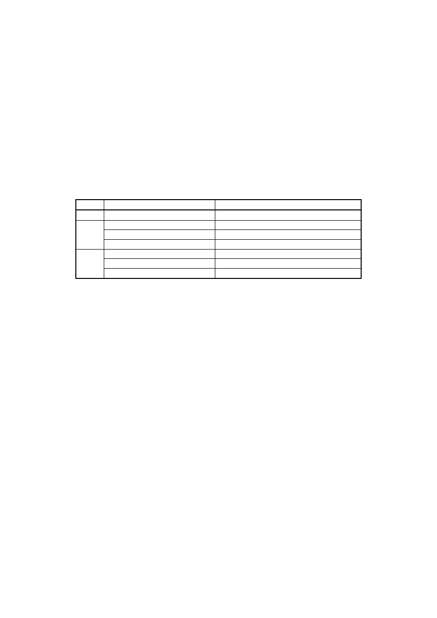
Table 1.1: Groups of tension components
Group Main tension element
Component
A
rod (bar)
tension rod (bar) system, prestressing bar
circular wire
spiral strand rope
circular and Z-wires
fully locked coil rope
B
circular wire and stranded wire
strand rope
circular wire
parallel wire strand (PWS)
circular wire
bundle of parallel wires
C
seven wire (prestressing) strand bundle of parallel strands
NOTE 1: Group A products in general have a single solid round cross section connected to end terminations by
threads. They are mainly used as
–
bracings for roofs, walls, girders
–
stays for roof elements, pylons
–
tensioning systems for steel-wooden truss and steel structures, space frames
NOTE 2: Group B products are composed of wires which are anchored in sockets or other end terminations and
are fabricated primarily in the diameter range of 5 mm to 160 mm, see EN 12385-2.
Spiral strand ropes are mainly used as
–
stay cables for aerials, smoke stacks, masts and bridges
–
carrying cables and edge cables for light weight structures
–
hangers or suspenders for suspension bridges
–
stabilizing cables for cable nets and wood and steel trusses
–
hand-rail cables for banisters, balconies, bridge rails and guardrails
Fully locked coil ropes are fabricated in the diameter range of 20 mm to 180 mm and are mainly used as
–
stay cables, suspension cables and hangers for bridge construction
–
suspension cables and stabilizing cables in cable trusses
–
edge cables for cable nets
–
stay cables for pylons, masts, aerials
BS EN 1993-1-11: 2006
Licensed copy: BSI USER 06 Document Controller, Midmac Contracting Co. W.L.L, Version correct as of 05/06/2011 15:07, (c) BSI

EN 1993-1-11: 2006 (E)
5
Structural strand ropes are mainly used as
–
stay cables for masts, aerials
–
hangers for suspension bridges
–
damper / spacer tie cables between stay cables
–
edge cables for fabric membranes
–
rail cables for banister, balcony, bridge and guide rails.
NOTE 3: Group C products need individual or collective anchoring and appropriate protection.
Bundles of parallel wires are mainly used as stay cables, main cables for suspension bridges and external
tendons.
Bundles of parallel strands are mainly used as stay cables for composite and steel bridges.
(4)
The types of termination dealt with in this part for Group B and C products are
–
metal and resin sockets, see EN 13411-4
–
sockets with cement grout
–
ferrules and ferrule securing, see EN 13411-3
–
swaged sockets and swaged fitting
–
U-bolt wire rope grips, see EN 13411-5
–
anchoring for bundles with wedges, cold formed button heads for wires and nuts for bars.
NOTE: For terminology see Annex C.
1.2 Normative
references
(1) This European Standard incorporates dated and undated reference to other publications. These
normative references are cited at the appropriate places in the text and the publications are listed hereafter.
For dated references, subsequent amendments or revisions to any of these publications apply to this
European Standard only when incorporated in it by amendment or revision. For undated references the latest
edition of the publication referred to applies.
EN 10138 Prestressing steels
Part 1 General requirements
Part 2 Wires
Part 3 Strands
Part 4 Bars
EN 10244 Steel wire and wire products – Non-ferrous metallic coatings on steel wire
Part 1 General requirements
Part 2 Zinc and zinc alloy coatings
Part 3 Aluminium coatings
EN 10264 Steel wire and wire products – Steel wire for ropes
Part 1 General requirements
Part 2 Cold drawn non-alloyed steel wire for ropes for general applications
Part 3 Cold drawn and cold profiled non alloyed steel wire for high tensile applications
Part 4 Stainless steel wires
EN 12385 Steel wire ropes – safety
Part 1 General requirements
Part 2 Definitions, designation and classification
BS EN 1993-1-11: 2006
Licensed copy: BSI USER 06 Document Controller, Midmac Contracting Co. W.L.L, Version correct as of 05/06/2011 15:07, (c) BSI

EN 1993-1-11: 2006 (E)
6
Part 3 Information for use and maintenance
Part 4 Stranded ropes for general lifting applications
Part 10 Spiral ropes for general structural applications
EN 13411 Terminations for steel wire ropes – safety
Part 3 Ferrules and ferrule-securing
Part 4 Metal and resin socketing
Part 5 U-bolt wire rope grips
1.3 Terms and definitions
(1)
For the purpose of this European Standard the following terms and definitions apply.
1.3.1
strand
an element of rope normally consisting of an assembly of wires of appropriate shape and dimensions laid
helically in the same or opposite direction in one or more layers around a centre
1.3.2
strand rope
an assembly of several strands laid helically in one or more layers around a core (single layer rope) or centre
(rotation-resistant or parallel-closed rope)
1.3.3
spiral rope
an assembly of a minimum of two layers of wires laid helically over a central wire
1.3.4
spiral strand rope
spiral rope comprising only round wires
1.3.5
fully locked coil rope
spiral rope having an outer layer of fully locked Z-shaped wires
1.3.6
fill factor f
the ratio of the sum of the nominal metallic cross-sectional areas of all the wires in a rope (A) and the
circumscribed area (A
u
) of the rope based on its nominal diameter (d)
1.3.7
spinning loss factor k
reduction factor for rope construction included in the breaking force factor K
1.3.8
breaking force factor (K)
an empirical factor used in the determination of minimum breaking force of a rope and obtained as follows:
4
k
f
K
π
=
where f is the fill factor for the rope
k is the spinning loss factor
NOTE: K-factors for the more common rope classes and constructions are given in the appropriate part of EN
12385.
BS EN 1993-1-11: 2006
Licensed copy: BSI USER 06 Document Controller, Midmac Contracting Co. W.L.L, Version correct as of 05/06/2011 15:07, (c) BSI

EN 1993-1-11: 2006 (E)
7
1.3.9
minimum breaking force (F
min
)
minimum breaking force which should be obtained as follows:
1000
2
min
K
R
d
F
r
=
[kN]
where d
is the diameter of the rope in mm
K
is the breaking force factor
R
r
is the rope grade in N/mm²
1.3.10
rope grade (R
r
)
a level of requirement of breaking force which is designated by a number (e.g. 1770 [N/mm²],
1960 [N/mm²])
NOTE: Rope grades do not necessarily correspond to the tensile strength grades of the wires in the rope.
1.3.11
unit weight (w)
the self weight of rope based on the metallic cross-section (A
m
) and the unit length taking account of the
densities of steel and the corrosion protection system
1.3.12
cable
main tension component in a structure (e.g. a stay cable bridge) which may consist of a rope, strand or
bundles of parallel wires or strands
1.4 Symbols
(1)
For this standard the symbols given in 1.6 of EN 1993-1-1 and 1.6 of EN 1993-1-9 apply.
(2)
Additional symbols are defined where they first occur.
NOTE: Symbols may have various meanings.
BS EN 1993-1-11: 2006
Licensed copy: BSI USER 06 Document Controller, Midmac Contracting Co. W.L.L, Version correct as of 05/06/2011 15:07, (c) BSI
EN 1993-1-11: 2006 (E)
8
2 Basis of design
2.1 General
(1)P The design of structures with tension components shall be in accordance with the general rules given
in EN 1990.
(2)
The supplementary provisions for tension components given in this standard should also be applied.
(3)
For improved durability the following exposure classes may be applied:
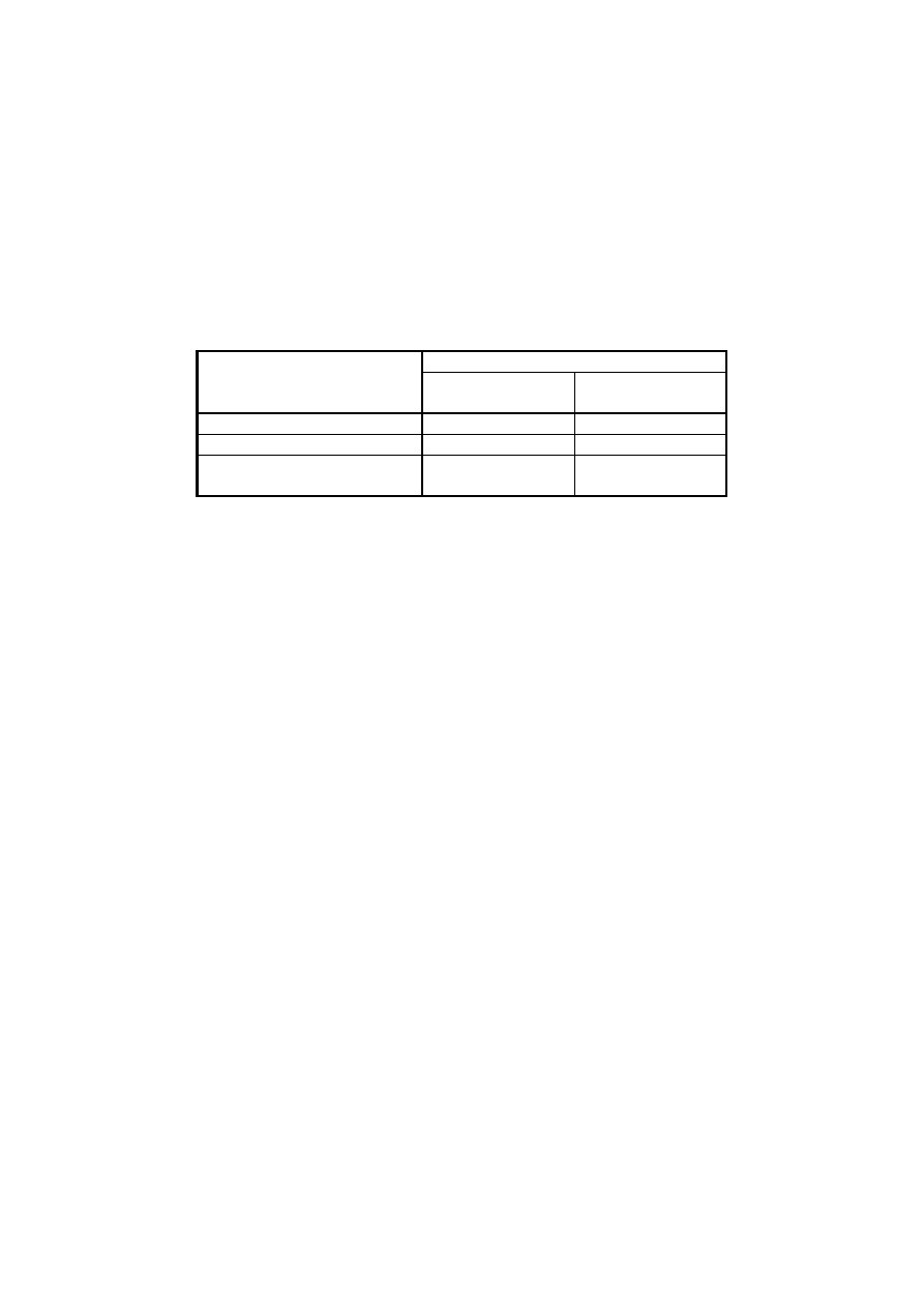
Table 2.1: Exposure classes
Corrosion action
Fatigue action
not exposed
externally
exposed externally
no significant fatigue action
class 1
class 2
mainly axial fatigue action
class 3
class 4
axial and lateral fatigue actions
(wind & rain)
– class
5
(4)
Connections of tension components to the structure should be replaceable and adjustable.
2.2 Requirements
(1)P The following limit states shall be considered in designing tension components:
1. ULS:
Applied axial loads shall not exceed the design tension resistance, see section 6.
2. SLS:
Stress and strain levels in the component shall not exceed the limiting values, see
section
7.
NOTE: For durability reasons, serviceability checks may govern over ULS-verifications.
3. Fatigue: Stress ranges from axial load fluctuations and wind and rain induced oscillations shall not
exceed the limiting values, see sections 0 and 0.
NOTE: Due to the difficulties in modelling the excitation characteristics of tension elements, SLS checks
should be carried out in addition to fatigue checks.
(2)
To prevent the likely de-tension of a tension component (i.e. the stress reaching below zero and
causing uncontrolled stability or fatigue or damages to structural or non structural parts) and for certain types
of structures, the tension components are preloaded by deformations imposed on the structure (prestressing).
In such cases permanent actions, which should consist of actions from gravity loads “G” and prestress “P”,
should be considered as a single permanent action “G+P” to which the relevant partial factors
Ȗ
Gi
should be
applied, see section 5.
NOTE: For other materials and methods of construction other rules for the combination of “G” and “P” may
apply.
(3)
Any attachments to prefabricated tension components, such as saddles or clamps, should be designed
for ultimate limit states and serviceability limit states using the breaking strength or proof strength of cables
as actions, see section 6. For fatigue see EN 1993-1-9.
NOTE: Fatigue action on the ropes is governed by the radius in the saddle or anchorage area (see Figure 6.1 for
minimum radius).
BS EN 1993-1-11: 2006
Licensed copy: BSI USER 06 Document Controller, Midmac Contracting Co. W.L.L, Version correct as of 05/06/2011 15:07, (c) BSI
EN 1993-1-11: 2006 (E)
9
2.3 Actions
2.3.1 Self weight of tension components
(1)
The characteristic value of the self weight of tension components and their attachments should be
determined from the cross-sectional area and the density of the materials unless data are given in the relevant
parts of EN 12385.
(2)
g
k
calculated as follows:
m
k
A
w
g
=
(2.1)
where A
m
is the cross-section in mm² of the metallic components
w [N/(mm³)] is the unit weight taking into account the density of steel including the corrosion
protection system, see Table 2.2
(3)
A
m
may be determined from
f
d
A
m
4
2
π
=
(2.2)
where d is the external diameter of rope or strand in mm, including any sheathing for corrosion protection
f is the fill-factor, see Table 2.2
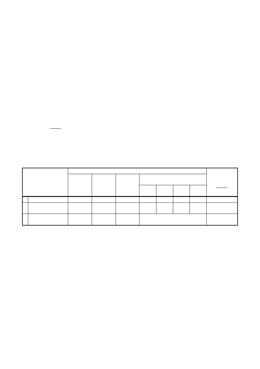
Table 2.2: Unit weight w and fill-factors f
Fill factor f
Number of wire layers around
core wire
Core
wires + 1
layer z-
wires
Core
wires + 2
layer z-
wires
Core
wires + >2
layer z-
wires
1 2 3-6
>6
unit weight
w
× 10
-7
»¼
º
«¬
ª
3
mm
N
1 Spiral
strand
ropes
0,77
0,76
0,75
0,73
830
2
Fully locked coil
ropes
0,81 0,84 0,88
830
3
Circular wire
strand ropes
0,56
930
(4)
For parallel wire ropes or parallel strand ropes the metallic cross-section may be determined from
A
m
= n a
m
(2.3)
where n is the number of identical wires or strands of which the rope is made
a
m
is the cross-section of a wire (derived from its diameter) or a (prestressing) strand (derived from
the appropriate standard)
(5)
For group C tension components the self weight should be determined from the steel weight of the
individual wires or strands and the weight of the protective material (HDPE, wax etc.)
2.3.2 Wind
actions
(1)
The wind effects to be taken into account should include:
–
the static effects of wind drag on the cables, see EN 1991-1-4, including deflections and bending effects
near the ends of the cable,
–
aerodynamic and other excitation causing possible oscillation of the cables, see section 8.
For spiral strand ropes, fully locked coil ropes or circular wire strand ropes the nominal self weight
may be
BS EN 1993-1-11: 2006
Licensed copy: BSI USER 06 Document Controller, Midmac Contracting Co. W.L.L, Version correct as of 05/06/2011 15:07, (c) BSI

EN 1993-1-11: 2006 (E)
10
2.3.3 Ice
loads
(1)
For ice loading see Annex B to EN 1993-3-1.
2.3.4 Thermal
actions
(1)
The thermal actions to be taken into account should include the effects of differential temperatures
between the cables and the structure.
(2)
For cables exposed externally the actions from differential temperature should be taken into account,
see EN 1991-1-5.
2.3.5 Prestressing
(1)
The preloads in cables should be such that, when all the permanent actions are applied, the structure
adopts the required geometric profile and stress distribution.
(2)
Facilities for prestressing and adjusting the cables should be provided and the characteristic value of
the preload should be taken as that required to achieve the required profile in (1) at the limit state under
consideration.
(3)
If adjustment of the cables is not intended to be carried out the effects of the variation of preloads
should be considered in the design of the structure.
2.3.6 Replacement and loss of tension components
(1)
The replacement of at least one tension component should be taken into account in the design as a
transient design situation.
NOTE: The National Annex may define the transient loading conditions and partial factors for replacement.
(2)
Where required a sudden loss of any one tension component should be taken into account in the design
as an accidental design situation.
NOTE 1: The National Annex may define where such an accidental design situation should apply and also give
the protection requirements and loading conditions, e.g. for hangers of bridges.
NOTE 2: In the absence of a rigorous analysis the dynamic effect of a sudden removal may conservatively be
allowed for by using the additional action effect E
d
:
E
d
= k
(
E
d2
_
E
d1
)
(2.4)
where k = 1,5
E
d1
represents the design effects with all cables intact;
E
d2
represents the design effects with the relevant cable removed.
2.3.7 Fatigue
loads
(1)
For fatigue loads see EN 1991.
BS EN 1993-1-11: 2006
Licensed copy: BSI USER 06 Document Controller, Midmac Contracting Co. W.L.L, Version correct as of 05/06/2011 15:07, (c) BSI

EN 1993-1-11: 2006 (E)
11
2.4 Design situations and partial factors
2.4.1 Transient design situation during the construction phase
(1)
For the construction phase the partial factor for permanent loads may be amended to suit the particular
design situation and limit state model.
NOTE: The National Annex may define the partial factor
Ȗ
Gi
for the construction phase. Recommended values
Ȗ
Gi
are:
Ȗ
G
= 1,10 for a short time period (only a few hours) for the installation of first strand in strand by strand
installations
Ȗ
G
= 1,20
for the installation of other strands
Ȗ
G
= 1,00
for favourable effects.
2.4.2 Persistent
design
situations during service
(1)
For ULS, SLS and fatigue verifications partial factors
Ȗ
M
may be based on
–
the severity of the conditions used for proving tests
–
the measures employed to suppress bending effects.
NOTE: Appropriate values for
Ȗ
M
are given in section 6.
3 Material
3.1 Strength of steels and wires
(1)
The characteristic values f
y
and f
u
for structural steel and f
0,2
or f
0,1
and f
u
for wires should be taken
from the relevant technical specifications.
NOTE 1: For steel see EN1993-1-1 and EN1993-1-4.
NOTE 2: For wires see EN 10264, Part 1 to Part 4.
NOTE 3: For ropes see EN 12385, Part 4 and Part 10.
NOTE 4: For terminations see EN 13411-3.
NOTE 5: For strands see EN 10138-3.
NOTE 6: The National Annex may give a maximum value for f
u
for durability reasons. The following values
are recommended:
–
steel wires
round wires:
nominal tensile strength: 1770 N/mm²
Z-wires:
nominal tensile strength: 1570 N/mm²
–
stainless steel wires:
round wires:
nominal tensile strength: 1450 N/mm²
3.2 Modulus of elasticity
3.2.1 Group A tension components
(1)
The modulus of elasticity for Group A tension components may be taken as E = 210000 N/mm²; for
systems made of stainless steels see EN 1993-1-4.
3.2.2 Group B tension components
(1)
The modulus of elasticity for Group B tension components should be derived from tests.
BS EN 1993-1-11: 2006
Licensed copy: BSI USER 06 Document Controller, Midmac Contracting Co. W.L.L, Version correct as of 05/06/2011 15:07, (c) BSI
EN 1993-1-11: 2006 (E)
12
NOTE 1: The modulus of elasticity is dependant on the stress level and whether the cable has been prestretched
and cyclically loaded and unloaded.
NOTE 2: The tension stiffness of the cable for tension components of Group B and C may be determined by
multiplying the modulus of elasticity by the metallic cross section A
m
.
(2)
The secant modulus should be used as the modulus of elasticity for structural analysis for persistent
design situations during service. Characteristic values should be obtained for each cable type and diameter
and should be determined after a sufficient number of (at least 5) load cycles between F
inf
and F
sup
to ensure
stable values are obtained, where F
inf
and F
sup
are the minimum and maximum cable forces respectively
under the characteristic permanent and variable actions.
(3)
For short test samples (sample length
10 x lay length) the value of creep obtained will be smaller
than for long cables.
NOTE 1: In the absence of more accurate values this effect may be taken into account for cutting to length by
applying an additional shortening of 0,15 mm/m.
NOTE 2: When test results are not available, nominal values of moduli of elasticity for use as first estimates are
given in Table 3.1. For further information see EN 10138.
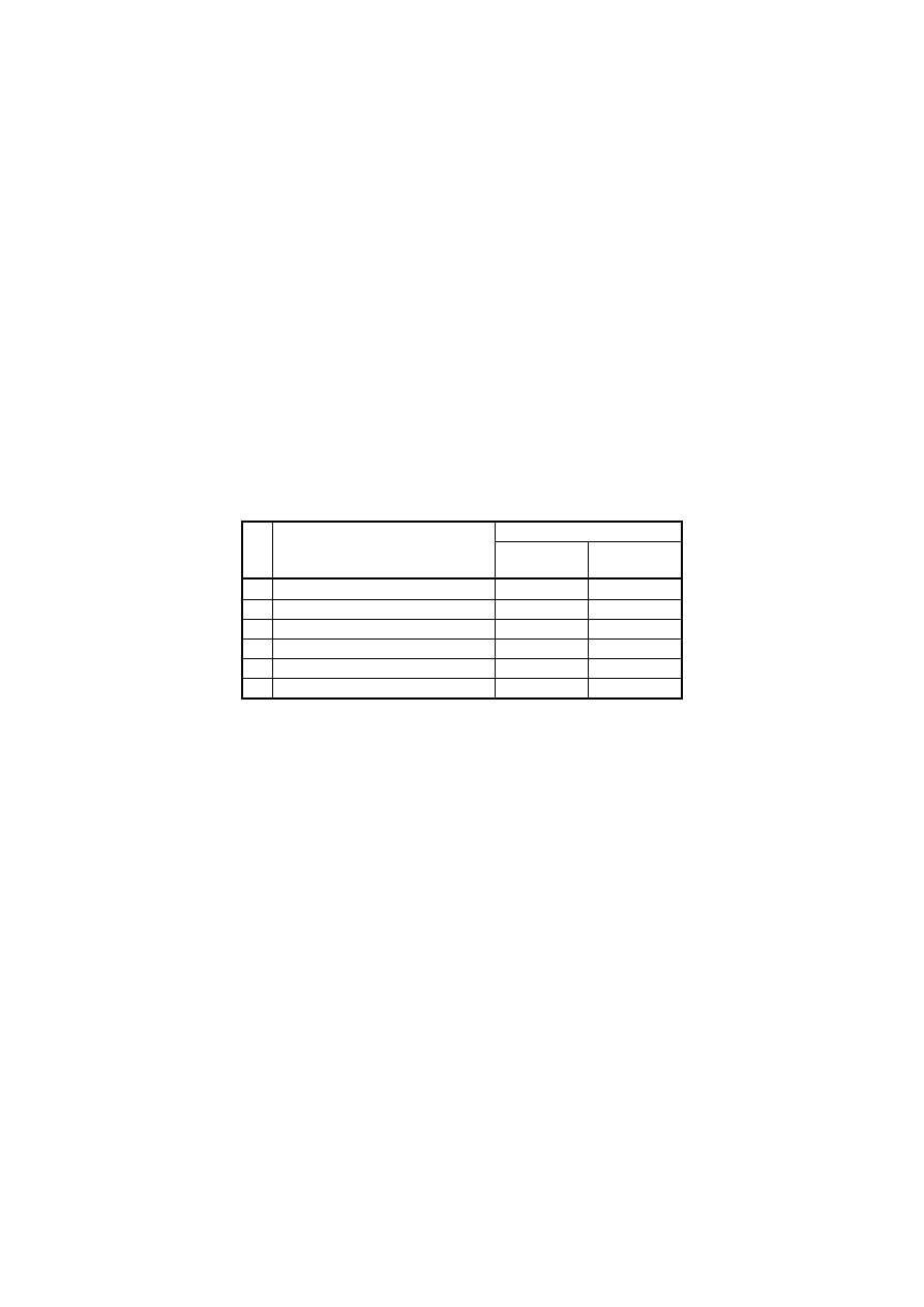
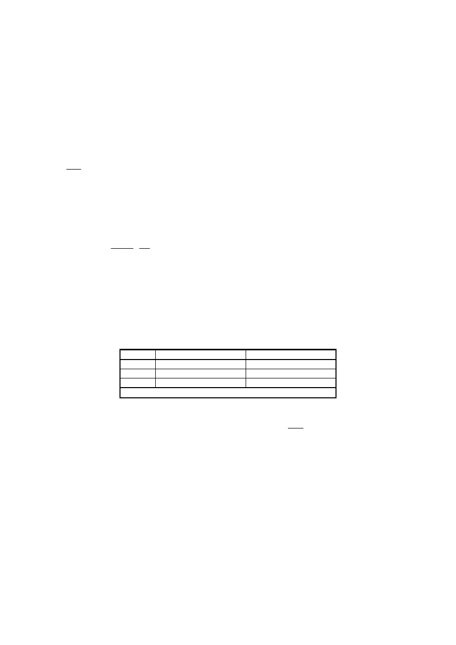
Table 3.1: Modulus of elasticity E
Q
corresponding to variable loads Q
E
Q
[kN/mm²]
High strength tension component
steel wires
stainless
steel wires
1
Spiral strand ropes
150
± 10
130
± 10
2
Fully locked coil ropes
160
± 10
–
3
Strand wire ropes with CWR
100
± 10
90
± 10
4
Strand wire ropes with CF
80
± 10
–
5
Bundle of parallel wires
205
± 5
–
6
Bundle of parallel strands
195
± 5
–
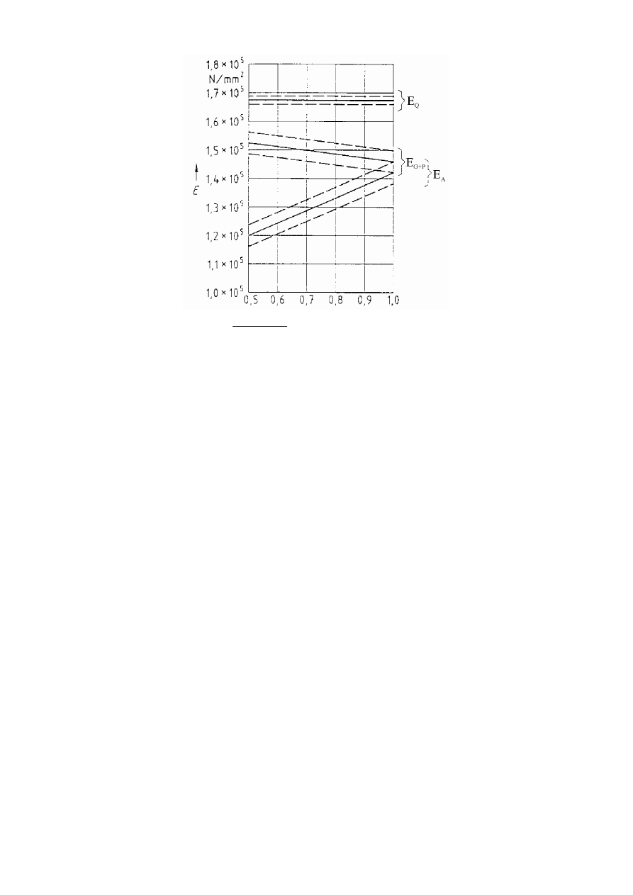
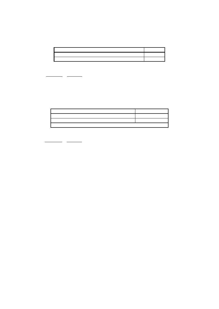
NOTE 3: The nominal values of the modulus of elasticity E for fully locked coil ropes are given in Figure 3.1.
These estimated values apply to cyclic loading range between 30 % and 40 % of the calculated breaking strength
F
uk
.
BS EN 1993-1-11: 2006
Licensed copy: BSI USER 06 Document Controller, Midmac Contracting Co. W.L.L, Version correct as of 05/06/2011 15:07, (c) BSI
EN 1993-1-11: 2006 (E)
13
– – – – – limiting value
→
+
+
+
Q
P
G
P
G
σ
σ
σ
––––––– mean value
σ
G+P
stress under characteristic permanent actions
σ
Q
maximum stress under characteristic variable actions
E
Q
modulus of elasticity for persistent design situations during service
E
G+P
modulus of elasticity for an appropriate analysis for transient design situations during
construction phase up to permanent load G+P
E
A
modulus of elasticity for cutting to length
Figure 3.1: Modulus of elasticity E for non pre-stretched fully locked coil ropes
for bridges
NOTE 4: Non pre-stretched Group B cables exhibit both elastic and permanent deformations when subjected to
static loading. It is recommended that such cables are pre-stretched before or after installation by cyclic loading
up to a maximum of 0,45
σ
uk
. For cutting to length such cables should be pre-stretched with a precision related to
the facilities for in-situ adjustment.
NOTE 5: For Figure 3.1 the following assumptions apply:
–
the lay length is greater than 10
× the diameter
–
the minimum value of stress is 100 N/mm²
The minimum value of stress is the lower bound of the elastic range.
3.2.3 Group C tension components
(1)
The modulus of elasticity for Group C tension components may be taken from EN 10138 or
Table 3.1
.
3.3 Coefficient of thermal expansion
(1)
The coefficient of thermal expansion should be taken as
Į
T
= 12
× 10
-6
per °C
for steel wires
Į
T
= 16
× 10
-6
per °C
for stainless steel wires
(3.1)
Text
deleted
BS EN 1993-1-11: 2006
Licensed copy: BSI USER 06 Document Controller, Midmac Contracting Co. W.L.L, Version correct as of 05/06/2011 15:07, (c) BSI

EN 1993-1-11: 2006 (E)
14
3.4 Cutting to length of Group B tension components
(1)
Strands may only be marked to length only for cutting at a prescribed cutting load.
(2)
For exact cutting to length the following data should be considered:
–
measured values of the elongation between
σ
A
and
σ
G+P
after cyclic loading according to 3.2.2(2)
–
difference between the design temperature (normally 10 °C) and the ambient temperature when cutting
to length
–
long term cable creep under loads
–
additional elongation of cable after installation of cable clamps
–
deformation after first loading.
NOTE: Cable creep and cone setting will continue after installation, therefore higher loads may be required
during erection to account for cable creep and setting of the pouring cone after cooling of molten metal and after
the initial load is applied.
3.5 Lengths and fabrication tolerances
(1)
The total length of the cable and all measuring points for the attachment of saddles and clamps should
be marked under a defined preload.
NOTE: The provisions of additional control markings allow for later checks of the exact length after parts have
been installed.
(2)
The fabrication tolerances should be taken into account after pre-stretching and cyclic loading and
unloading.
(3)
When structures are sensitive to deviations from nominal geometrical values (e.g. by creep), facilities
for adjustments should be provided.
3.6 Friction
coefficients
(1)
The friction coefficient between fully locked coil cables and steel attachments (clamps, saddles,
fittings) should be determined from tests.
NOTE: The friction forces may be reduced by reduction of the diameter if tension is increased.
(2)
The friction coefficient for other types of cables should also be determined from tests, see Annex A.
4 Durability of wires, ropes and strands
4.1 General
(1)
For Group B and C tension components with exposure classes 2, 4 and 5 according to Table 2.1 the
corrosion protection system should be as follows:
1. Individual wires should be protected against corrosion;
2. The rope interior should be protected to stop the ingress of moisture;
3. The outer surface should be protected against corrosion.
(2)
Group C tension components as defined in Table 1.1 should have two layers of corrosion protection
systems with an interface or inner filler between the two systems.
BS EN 1993-1-11: 2006
Licensed copy: BSI USER 06 Document Controller, Midmac Contracting Co. W.L.L, Version correct as of 05/06/2011 15:07, (c) BSI

EN 1993-1-11: 2006 (E)
15
(3) At clamps and anchorages additional corrosion protection should be applied to prevent water
penetration.
(4)
For transport, storage and handling, see Annex B.
4.2 Corrosion protection of individual wires
(1)
Each steel wire within group B and C tension components should be coated with either zinc or zinc
alloy compound.
(2)
For group B tension components zinc or zinc alloy coating for round wires should be in accordance
with EN 10264-2, class A. For shaped wires coating should comply with EN 10264-3, class A.
NOTE 1: Generally Z-shaped wires are galvanized with a thicker coating thickness of up to 300g/m² to allow
for a reduction in thickness on sharp corners.
NOTE 2: Wires coated with a Zn95Al5 alloy have a much improved corrosion protection than galvanizing with
zinc of the same coating thickness. Round and Z-shaped wires can be coated with a Zn95Al5 basis weight.
(3)
For Group C tension components, coating of wires should comply with EN 10138.
4.3 Corrosion protection of the interior of Group B tension components
(1)
All interior voids within cables should be filled with an active or passive inner filling that should not
be displaced by water, heat or vibration.
NOTE 1: Active fillers are polyurethane-oil based with zinc dust paint.
NOTE 2: Passive inner fillers can be permanent elastic-plastic wax or aluminium flake in hydrocarbon resin.
NOTE 3: The inner filling applied during the manufacture of the tension components can extrude when the
component is loaded (bleeding), so that other corrosion protection measures should be timed accordingly.
NOTE 4: The inner filling should be selected to avoid any incompatibility with the other corrosion protection
measures being applied to the cable.
4.4 Corrosion protection of the exterior of Group B tension components
(1)
After construction additional corrosion protection measures should be applied to compensate for any
damage incurred and for the loss of zinc.
NOTE: This protection may consist of polyethylene sheathing or zinc rich paint. The minimum thickness of
polyethylene should be equal to the outer rope diameter divided by 15 and should not be less than 3 mm.
The paint system should comprise a minimum of:
–
2
× 50 μm polyurethane with zinc dust prime coats;
–
2
× 125 μm polyurethane with iron mica finishing coats.
(2) Cables with stainless steel wires and stainless steel terminations without additional corrosion
protection should comply with the relevant corrosion resistance class.
NOTE 1: The National Annex may specify the corrosion resistance classes for stainless steel.
NOTE 2: Zn95Al5-coated wires provide up to 3 times better resistance compared with heavy zinc coated wires
under identical conditions.
BS EN 1993-1-11: 2006
Licensed copy: BSI USER 06 Document Controller, Midmac Contracting Co. W.L.L, Version correct as of 05/06/2011 15:07, (c) BSI

EN 1993-1-11: 2006 (E)
16
4.5 Corrosion protection of Group C tension components
(1)
Group C tension components should normally be sheathed using steel or polyethylene tube complying
to relevant standards with the space between the inside of the sheath and the cable filled with a suitable
corrosion protection compound or cement grout.
(2) Alternatively
polyethylene sheathing extruded directly or epoxy coating over the individual strands or
cables may be used.
(3)
The sheaths used for the cables should be made
(4)
Voids should be filled with continuous hydrophobic materials with no detrimental effects on the
tension components. Alternatively, the cable may be protected by circulation of the dry air within the sheath.
NOTE 1: Continuous hydrophobic materials are soft fillers, such as grease, wax or soft resin, or hard fillers,
such as cement. The suitability of the fillers should be proved by tests. The choice of the acceptable fillers may
be specified in the National Annex.
NOTE 2: Corrosion protection of main cables of suspension bridges requires a special approach. After
compacting the main cable into the required cross-sectional area the cable is closely wrapped with tensioned
galvanized soft wire laid in a suitable paste sufficient to fill completely the voids between the outer cable wires
and the wrapping wire. After removal of the surplus paste from outside of the wrapping wire the zinc-coated
surface is cleaned and painted. Special treatment is required for suspension bridge cable anchorages where the
wrapping wire is removed. Dehumidification of the air around the wires is a common method of protection.
4.6 Corrosion protection at connections
(1)
Provision should be made to prevent rainwater running down the cable from entering the clamps,
saddles and anchorages.
(2)
Cable structure connections should be sealed.
5 Structural
analysis
5.1 General
(1)P The analysis shall be carried out for the limit states considered for the following design conditions:
1. the transient construction phase
2. the persistent service conditions after completion of construction.
5.2 Transient construction phase
(1)
The construction process including forming cables, pre-stressing and the geometry of the structure
should be planned such that the following conditions are attained:
–
the required geometric form
–
a permanent stress distribution that satisfies the serviceability and ultimate limit state conditions for all
design situations.
(2)
For compliance with control measures throughout the entire construction process (e.g. measurements
of shape, gradients, deformations, frequencies or forces) all calculations should be carried out using
characteristic values of permanent loads, imposed deformations and any imposed actions.
(3)
Where ultimate limit states during pre-stressing are controlled by the differential effects of gravity
loads “G” and prestress “P”, the partial factor
γ
P
to be applied to “P” should be defined for that situation.
impermeable to water
at the connections to
the anchorages. The joints should be designed so that they do not break, when the sheath is subjected to tension.
BS EN 1993-1-11: 2006
Licensed copy: BSI USER 06 Document Controller, Midmac Contracting Co. W.L.L, Version correct as of 05/06/2011 15:07, (c) BSI

EN 1993-1-11: 2006 (E)
17
NOTE: The National Annex may define
γ
P
, the value of
γ
P
= 1,00 is recommended
.
5.3 Persistent design situation during service
(1)
For any persistent design situation during the service the permanent actions “G” from gravity and
preloads or prestressing “P” should be combined in a single permanent action “G + P” corresponding to the
permanent shape of the structure.
(2)
For the verification of the serviceability limit states the action “G + P” should be included in the
relevant combination of action. For the verification of the ultimate limit state EQU or STR (see EN 1990) the
permanent actions “G + P” should be multiplied by the partial factor
Ȗ
G sup
, when the effects of permanent
action and of variable actions are adverse. If the permanent actions “G + P” are favourable they should be
multiplied by the partial factor
Ȗ
G inf
.
NOTE: The National Annex may give guidance where outside the scope of EN 1993 the partial factor
Ȗ
G
to “G
+ P” may be used.
(3)
When nonlinear action effects from deformations are significant during service these effects should be
taken into account, see 5.4.
5.4 Non-linear effects from deformations
5.4.1 General
(1) The effects of deformations from catenary effects and the shortening and lengthening of the
components including the effects due to creep should be taken into account.
5.4.2 Catenary
effects
(1)
Catenary effects may be taken into account by using the effective modulus E
t
to each cable or its
segment:
3
2
2
12
1
σ
E
w
E
E
t
"
+
=
(5.1)
E is the modulus of elasticity of the cable in N/mm²
w is the unit weight according to Table 2.2 in N/mm³
Ɛ is the horizontal span of the cable in mm
ı is the stress in the cable in N/mm². For situations according to 5.3 it is
σ
G+P
.
5.4.3 Effects of deformations on the structure
(1)
For the 2
nd
order analysis the action effects due to variable loads should take into account the initial
geometrical form of the structure due to the permanent loading “G + P” for a given temperature T
0
.
(2)
For the 2
nd
order analysis at serviceability limit state the action effects should be determined using the
characteristic load combination. These action effects may also be used for ultimate limit state verifications
according to 7.2.
(3) For
2
nd
order analysis for the non-linear behaviour of structures (over-linear structural response) at the
ultimate limit state the required permanent geometrical form of the structure at the reference temperature T
0
should be combined with the stresses due to “
Ȗ
G
(G + P)”. Design values of the variable actions
2
2
1
k
Q
k
Q
Q
Q
ψ
γ
γ
+
may be applied together with the appropriate assumptions for the imperfection of the
structure.
NOTE: For
Ȗ
G
see 5.3(2).
BS EN 1993-1-11: 2006
Licensed copy: BSI USER 06 Document Controller, Midmac Contracting Co. W.L.L, Version correct as of 05/06/2011 15:07, (c) BSI
EN 1993-1-11: 2006 (E)
18
6 Ultimate
limit
states
6.1 Tension
rod
systems
(1)
Tension rod systems should be designed for the ultimate limit state according to EN 1993-1-1 or EN
1993-1-4 depending on the type of steel used.
6.2 Pre-stressing bars and Group B and C components
(1)P For the ultimate limit state it shall be verified that
1
≤
Rd
Ed
F
F
(6.1)
where F
Ed
is the design value of the axial rope force
F
Rd
is the design value of the tension resistance.
(2)
The design value of the tension resistance F
Rd
should be taken as follows:
¿
¾
½
¯
®
=
R
k
R
uk
Rd
F
F
F
γ
γ
;
5
,
1
min
(6.2)
where F
uk
is the characteristic value of the breaking strength,
F
k
is the characteristic value of the proof strength of the tension component as given in
Table 6.1
;
Ȗ
R
is the partial factor.
NOTE 1: F
uk
corresponds to the characteristic value of the ultimate tensile strength.
Table 6.1: Characteristic value of the proof strength
of tension components
Group Relevant
standard
F
k
A EN
10138-1
F
0,1k
*)
B EN
10264
F
0,2k
C EN
10138-1
F
0,1k
*) For prestressing bars see EN 1993-1-1 and EN 1993-1-4
NOTE 2: The check against F
k
ensures that the component will remain elastic when the actions attain their
design value. For components (e.g. fully locked coil ropes) where
50
,
1
uk
k
F
F
≥
this check is not required.
NOTE 3: By tests on delivery it is demonstrated that the experimental values F
uke
and F
ke
satisfy the
requirement
F
uke
> F
uk
,
F
ke
> F
k
,
see EN 12385, Part 1.
NOTE 4: The partial factor
Ȗ
R
may be specified in the National Annex. The value is dependent on whether or
not measures are applied at the rope ends to reduce bending moments from cable rotations,
see 7.1(2).
Ȗ
R
in Table 6.2 are recommended.
F
k
The values for
BS EN 1993-1-11: 2006
Licensed copy: BSI USER 06 Document Controller, Midmac Contracting Co. W.L.L, Version correct as of 05/06/2011 15:07, (c) BSI
EN 1993-1-11: 2006 (E)
19
Table 6.2: Recommended
Ȗ
R
– values
Measures to minimise
bending
stresses at the
anchorage
Ȗ
R
Yes 0,90
No 1,00
(3)
For prestressing bars and group C tension components the characteristic value of the breaking strength
should be determined from:
F
uk
= A
m
f
uk
(6.3)
where A
m
is the metallic cross-section, see 2.3.1;
f
uk
is the characteristic value of the tensile strength of bars, wires or (prestressing) strands
according to the relevant standard.
(4)
For group B tension components F
uk
should be calculated as:
F
uk
= F
min
k
e
(6.4)
where F
min
is determined according to EN 12385-2 as:
[ ]
kN
R
d
K
F
r
1000
2
min
=
(6.5)
where K is the minimum breaking force factor taking account of the spinning loss;
d is the nominal diameter of the rope in mm;
R
r
is the rope grade in N/mm²;
k
e
is the loss factor given in
Table 6.3
for some types of end terminations.
NOTE: K, d, R
r
are specified for all ropes in the EN 12385-2.
Table 6.3: Loss factors k
e
Type of termination
Loss factor k
e
Metal filled socket
1,0
Resin filled socket
1,0
Ferrule-secured eye
0,9
Swaged socket
0,9
U-bolt grip
0,8 *)
*) For U-bolt grip a reduction of preload is possible.
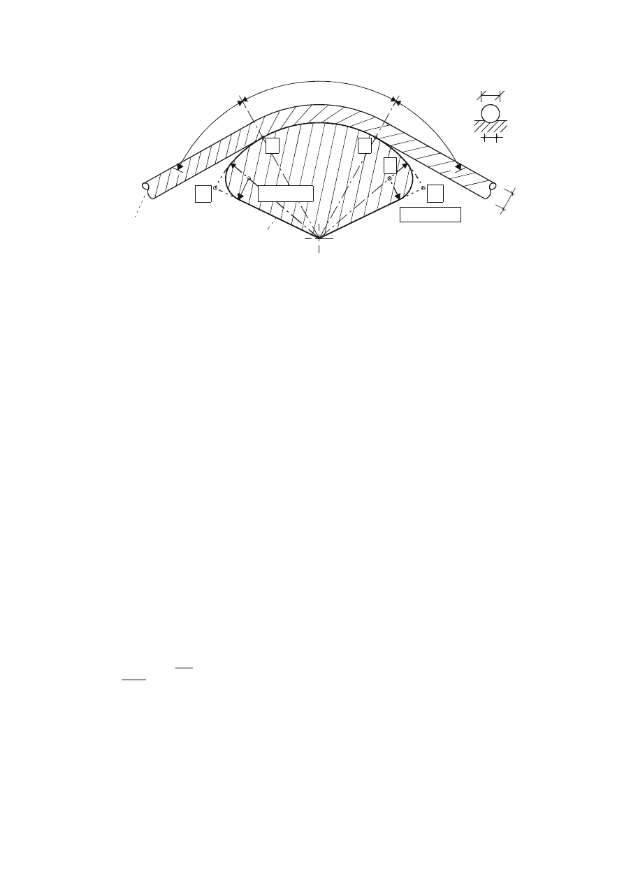
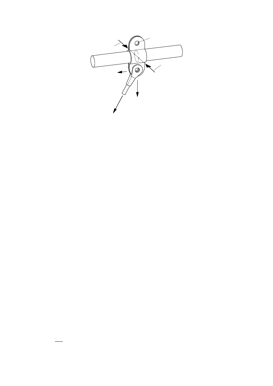
6.3 Saddles
6.3.1
Geometrical conditions
(1)
Where the saddle proportions meet the requirements given in Figure 6.1, (2) and (3), stresses due to
curvature of wires may be neglected in the design.
BS EN 1993-1-11: 2006
Licensed copy: BSI USER 06 Document Controller, Midmac Contracting Co. W.L.L, Version correct as of 05/06/2011 15:07, (c) BSI
EN 1993-1-11: 2006 (E)
20
1 strand/rope
2 saddle
L
2
length of strand/rope between the two theoretical tangent points T
1
under
the most unfavourable characteristic combination of loads and the
catenary effects
Δ
L
2
additional length of wrap
Figure 6.1: Bedding of a strand/rope over a saddle
NOTE: Compliance with the requirements in (1) above will result in the breaking resistance of the strand and
rope being reduced by not more than 3 %.
(2) The
radius
r
1
of the saddle should not be less than the greater of 30d or r
1
400
∅
, where
∅
is the diameter of wire;
d
is the diameter of the cable;
d'
is the contact width.
(3)
The value of r
1
may be reduced to 20d when the bedding of the rope on at least 60% of the diameter is
coated with soft metal or zinc spray with a minimum thickness of 1 mm.
(4)
Smaller radii may be used for spiral ropes where justified by tests.
NOTE: The locations of T
1
and T
2
should be determined for the relevant load cases taking into account the
movements of bearings and cables.
6.3.2
Slipping of cables over saddles
(1)
To prevent slippages the following condition should be met:
°¿
°
¾
½
°¯
°
®
≤
¿
¾
½
¯
®
fr
M
e
F
F
Ed
Ed
,
2
1
max
γ
μα
(6.6)
where F
Ed1
and F
Ed2
are the design values of the maximum and minimum force respectively on either side
of the
saddle;
ȝ is the coefficient of friction between cable and saddle;
Į is the angle in radians, of the cable passing over the saddle;
Ȗ
M,fr
is the partial factor for friction.
NOTE: The partial factor
Ȗ
Mfr
may be given in the National Annex. The value
Ȗ
Mfr
= 1,65 is recommended.
r
1
30 d
d
2
0.03
cable
L
L
2
L
2
L
2
L
2
2
d
d
'
1
2
T
1
T
r
2
T
T
r
2
20 mm
saddle
1
a)
α
b)
2
BS EN 1993-1-11: 2006
Licensed copy: BSI USER 06 Document Controller, Midmac Contracting Co. W.L.L, Version correct as of 05/06/2011 15:07, (c) BSI
EN 1993-1-11: 2006 (E)
21
(2)
If (1) is not satisfied, clamps should be provided to impart an additional radial clamping force F
r
such
that
»
»
¼
º
«
«
¬
ª
≤
−
fr
M
e
F
F
k
F
Ed
Mfr
r
Ed
,
2
1
γ
μα
γ
μ
(6.7)
where k
is normally as 2,0 where there is full friction developed between the saddle grooves and the
clamp and F
r
does not exceed the resistance of the cable to clamping forces, see 6.3.3, other k =
1,0;
γ
M,fr
is the partial factor for friction resistance.
(3) In
determining
F
r
from preloaded bolts the following effects should be considered:
a) long term creep;
b) reduction of diameter if tension is increased;
c) compaction/bedding down of cable or ovalisation;
d) reduction of preload in clamp bolts by external forces;
e) differential temperature.
6.3.3 Transverse
pressure
(1)P The transverse pressure q
Ed
due to the radial clamping force F
r
shall be limited to
1
≤
Rd
Ed
q
q
(6.8)
where
2
/
L
d
F
q
r
Ed
=
and
d
d
d
≤
≤
/
6
,
0
, (for
/
d
see Figure 6.1b));
bed
M
Rk
Rd
q
q
,
γ
=
q
Rk
is the limiting value of the transverse pressure which shall be determined from tests;
Ȗ
M,bed
is the partial factor.
NOTE: For calculating q
Rd
the pressure from F
Ed1
need not be considered as it is covered by the rules in 6.3.1.
(2)
In the absence of tests the limiting values of the transverse pressure q
Rk
should be obtained from
Table
6.4
.
NOTE 1: The use of the limiting values q
Rk
with
Ȗ
M,bed
= 1,00 should lead to a reduction of not more than 3 % of
the breaking strength of the cable.
Table 6.4: Limiting values q
Rk
q
Rk
[N/mm²]
Type of cable
Steel clamps and saddles
Cushioned clamps and saddles
Fully locked coil rope
40
100
Spiral strand rope
25
60
NOTE 2: Cushioned clamps should have a layer of soft metal or sprayed zinc coating with a minimum
thickness of 1 mm.
BS EN 1993-1-11: 2006
Licensed copy: BSI USER 06 Document Controller, Midmac Contracting Co. W.L.L, Version correct as of 05/06/2011 15:07, (c) BSI

EN 1993-1-11: 2006 (E)
22
6.3.4
Design of saddles
(1)
Saddles should be designed for a cable force of k times the characteristic breaking strength F
uk
of the
cables.
NOTE: The factor k may be specified in the National Annex. The value of k = 1,10 is recommended.
6.4 Clamps
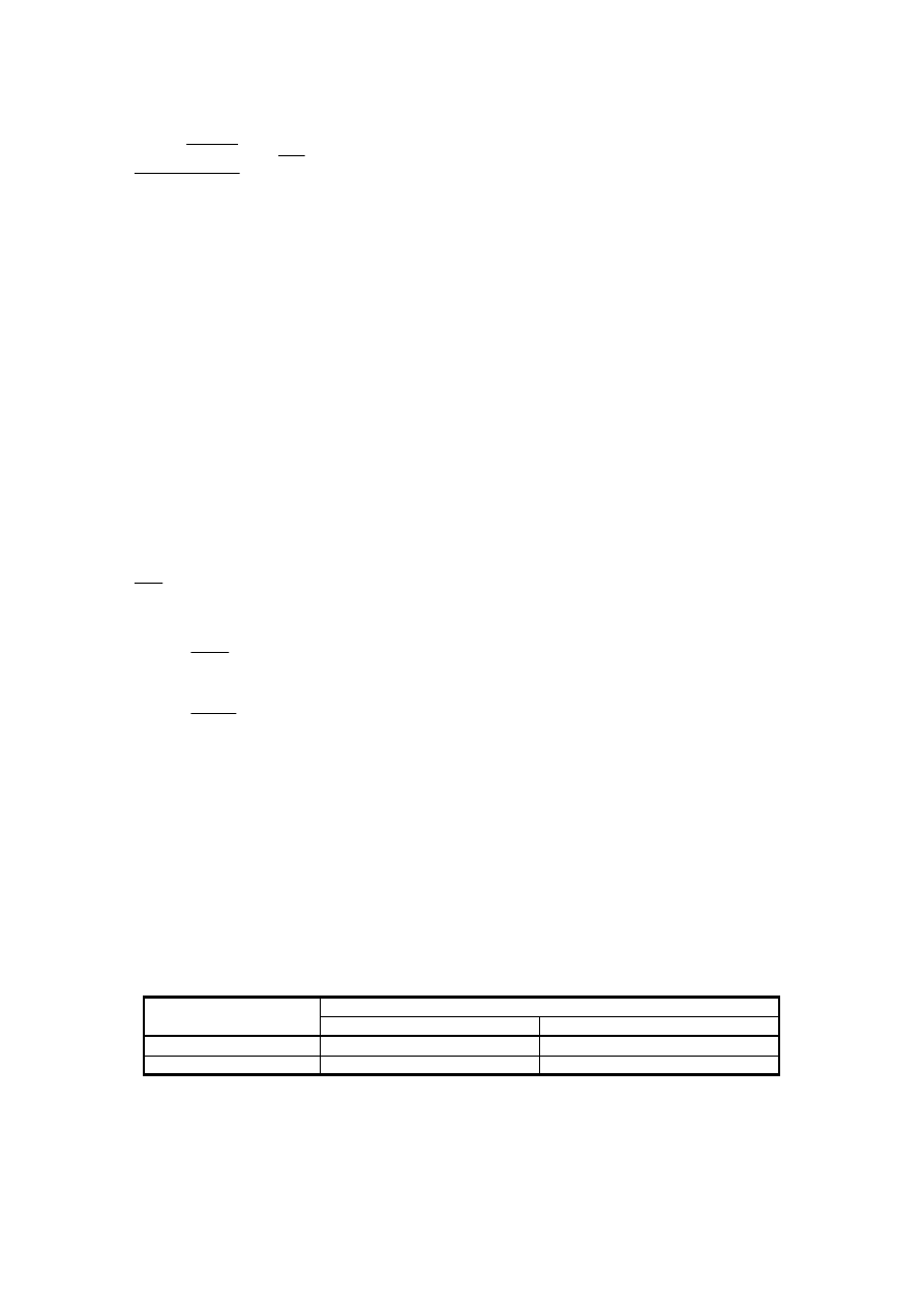
6.4.1
Slipping of clamps
(1)P Where clamps transmit longitudinal forces to a cable and the parts (see Figure 6.2) are not
mechanically keyed together, slipping shall be prevented by verifying
(
)
fr
M
r
Ed
Ed
F
F
F
,
|
|
γ
μ
+
≤
⊥
(6.9)
where
|
|
Ed
F
is the component of external design load parallel to the cable;
⊥
Ed
F
is the component of the external design load perpendicular to the cable;
F
r
is the radial clamping force considered that may be reduced by items in 0(3);
ȝ
is the coefficient of friction;
Ȗ
M,fr
is the partial factor for friction.
NOTE 1: The partial factor
Ȗ
M,fr
may be specified in the National Annex.
Ȗ
M,fr
= 1,65 is recommended.
NOTE 2: F
r
may be increased or reduced by external forces according to the manner in which they are applied
to the cable clamp.
6.4.2 Transverse
pressure
(1)
The transverse pressure due to the application of the greater of
⊥
Ed
F
or
r
Ed
F
F
+
⊥
should meet the
requirements of 6.3.3.
6.4.3
Design of clamps
(1)
Clamps and their fittings connecting components such as hangers to a main cable should be designed
for a notional force equal to 1,15 times the
characteristic value of the proof strength
F
k
of the
secondary components clamped, see Figure 6.2.
BS EN 1993-1-11: 2006
Licensed copy: BSI USER 06 Document Controller, Midmac Contracting Co. W.L.L, Version correct as of 05/06/2011 15:07, (c) BSI
EN 1993-1-11: 2006 (E)
23
⊥
Ed
F
Ed
F
||
1
2
2
1 hole for preloaded bolts
2 preload
F
r
from preloaded bolts
Figure 6.2: Clamp
NOTE: F
k
is not directly related to ULS. By the use of F
k
capacity design (see EN 1993-1-1, 1.5.8) is applied.
7 Serviceability
limit
states
7.1 Serviceability
criteria
(1)
The following serviceability criteria should be considered.
1. Deformations or vibrations;
2. Elastic service conditions.
NOTE 1: Limits for deformations or vibrations may result in a stiffness requirement governed by the structural
system, the dimensions and the preloading of high strength tension components, and by the slipping resistance of
attachments.
NOTE 2: Limits to retain elastic behaviour and durability are related to maximum and minimum values of
stresses for serviceability load combinations.
(2)
Bending stresses in the anchorage zone may be reduced by suitable measures (e.g. neoprene pads for
transverse loading).
7.2 Stress limits
(1)
Limiting stress may be specified for the characteristic load combination for the following purposes:
–
to keep stresses in the elastic range for the relevant design situations during construction and in the
service phase;
–
to limit strains such that corrosion control measures are not affected, i.e. cracking of sheaths, hard fillers,
opening of joints etc., and also to cater for uncertainty in the fatigue design;
–
ULS verifications for linear and sub-linear structural response to actions.
(2)
Stress limits should be related to the breaking strength as follows:
m
uk
uk
A
F
=
σ
(7.1)
see equation (6.3).
BS EN 1993-1-11: 2006
Licensed copy: BSI USER 06 Document Controller, Midmac Contracting Co. W.L.L, Version correct as of 05/06/2011 15:07, (c) BSI
EN 1993-1-11: 2006 (E)
24
NOTE 1: The National Annex may give values for stress limits f
const
and f
SLS
. Recommended values for stress
limits f
const
are given in Table 7.1 for the construction phase and for stress limits f
SLS
in Table 7.2 for service
conditions.
Table 7.1: Stress limits f
const
for the construction phase
Stage of installation
f
const.
First tension components for only a few hours
0,60
ı
uk
After instalment of other tension components
0,55
ı
uk
NOTE 2: The stress limits follow from
F
R
uk
F
R
uk
const
f
γ
γ
σ
γ
γ
σ
66
,
0
50
,
1
=
=
(7.2)
with
Ȗ
R
× Ȗ
F
= 1,0
× 1,10 = 1,10 for short term situations
Ȗ
R
× Ȗ
F
= 1,0
× 1,20 = 1,20 for long term situations
Table 7.2: Stress limits f
SLS
for service conditions
Loading conditions
f
SLS
Fatigue design including bending stresses *)
0,50
ı
uk
Fatigue design without bending stresses
0,45
ı
uk
*) Bending stresses may be reduced by detailing measures, see
7. 1( ).
NOTE 3: The stress limits follow from
F
R
uk
F
R
uk
SLS
f
γ
γ
σ
γ
γ
σ
66
,
0
50
,
1
=
=
(7.3)
with
Ȗ
R
× Ȗ
F
= 0,9
× 1,48 = 1,33 with bending stresses
Ȗ
R
× Ȗ
F
= 1,0
× 1,48 = 1,48 without bending stresses
where
Ȗ
F
≈ Ȗ
Q
= 1,50
≈ 1,48
NOTE 4: The stress limit f
SLS
= 0,45
ı
uk
is used for testing, see Annex A.
8
Vibrations of cables
8.1 General
(1)
For cables exposed externally (e.g. stay cables) any wind-induced vibrations during and after erection
and their impact on safety should be checked.
(2)
Aerodynamic forces on the cable may be caused by:
a) buffeting (from turbulence in the air flow)
b) vortex shedding (from von Karman vortexes in the wake behind the cable)
c) galloping (self induction)
d) wake galloping (fluid-elastic interaction of neighbouring cables)
e) interaction of wind, rain and cable
NOTE: Galloping is not possible on a cable with a circular cross-section for symmetry reasons. This
phenomenon may arise with cables where apparent shapes have altered, due to formation of layers of ice or dust.
Forces due to c), d) and e) are a function of the motion of the cable (feedback) and are due to the ensuing
aeroelastic instability leading to vibrations of large amplitudes starting at a critical wind speed. As the
mechanism of dynamic excitation cannot yet be modelled with sufficient accuracy to make reliable predictions,
measures should be provided to limit unforeseen vibrations.
BS EN 1993-1-11: 2006
2
Licensed copy: BSI USER 06 Document Controller, Midmac Contracting Co. W.L.L, Version correct as of 05/06/2011 15:07, (c) BSI

EN 1993-1-11: 2006 (E)
25
(3)
Cable vibrations may also be caused by dynamic forces acting on other parts of the structure (girder,
pylon).
NOTE: This phenomenon is often referred to as “parametric excitation” and is responsible for large amplitude
vibrations where the eigen-frequency of the cable stays and the structure overlap.
8.2
Measures to limit vibrations of cables
(1)
Structures supported by cables should be monitored for excessive wind and rain induced vibrations
either by visual inspection or other methods that allow a more accurate determination of their amplitudes,
modes and frequencies.
(2) In the design of a cable structure provisions should be made for installing vibration controlling
measures during or after erection.
(3)
Such measures may include:
a) modification of cable surface (aerodynamic shape);
b) damping devices;
c) stabilizing cables (e.g. tie-down cables with appropriate connections).
8.3 Estimation
of
risks
(1)
Vibration of cables due to rain and wind should be prevented by design; this can involve utilising
cable stays with texturing.
(2)
The risk of vibration increases with cable stay length. Short cable stays (
less
than
70
m
to
80
m)
generally impose no risk, except that in the case of a particularly unstable structure (poorly shaped and
flexible deck) parametric resonance occurs. Dampers are therefore not needed for short cable stays.
(3)
For long cable stays with length greater than 80 m provisions should be made for the installation of
dampers to ensure that the critical damping ratio exceeds 0,5 %. Dampers may be dispensed with on the back
span cable stays where it is unlikely to have any major displacement of the anchorage as the span is short.
(4)
The risk of parametric resonance should be assessed at the design stage by means of a detailed study
of the
eigen
modes
of
the
structure
and
cable
stays,
considering
the
ratio
of
angular
frequencies
anchorage displacement for each mode.
(5)
Measures should be taken to avoid overlapping of frequencies, i.e. situations where the cable stay’s
frequency of excitation
Ω
is within 20 % of the structure’s frequency
ω
n
or 2
ω
n
. If necessary, stability cables
can be used to offset the modal angular frequencies of the cable stays.
(6)
For users comfort and safety, the amplitude of cable stay vibration should be limited using a response
criterion such that with a moderate wind velocity of 15 m/s the amplitude of cable stay vibration should not
exceed L/500, where L is the length of the cable.
9 Fatigue
9.1 General
(1)
The fatigue endurance of tension components in exposure classes 3, 4 or 5 to Table 2.1 should be
determined using the fatigue actions from EN 1991 and the appropriate category of structural detail.
(2) Fatigue failure of cable systems usually occurs at anchorages, saddles or clamps. The effective
category of detail at these locations should preferably be determined from tests representing the actual
BS EN 1993-1-11: 2006
and
Licensed copy: BSI USER 06 Document Controller, Midmac Contracting Co. W.L.L, Version correct as of 05/06/2011 15:07, (c) BSI
EN 1993-1-11: 2006 (E)
26
configuration used and reproducing any flexural effect or transverse stresses likely to occur in practice. The
test evaluation should be carried out according to EN 1990 – Annex D.
9.2 Fluctuating
axial
loads
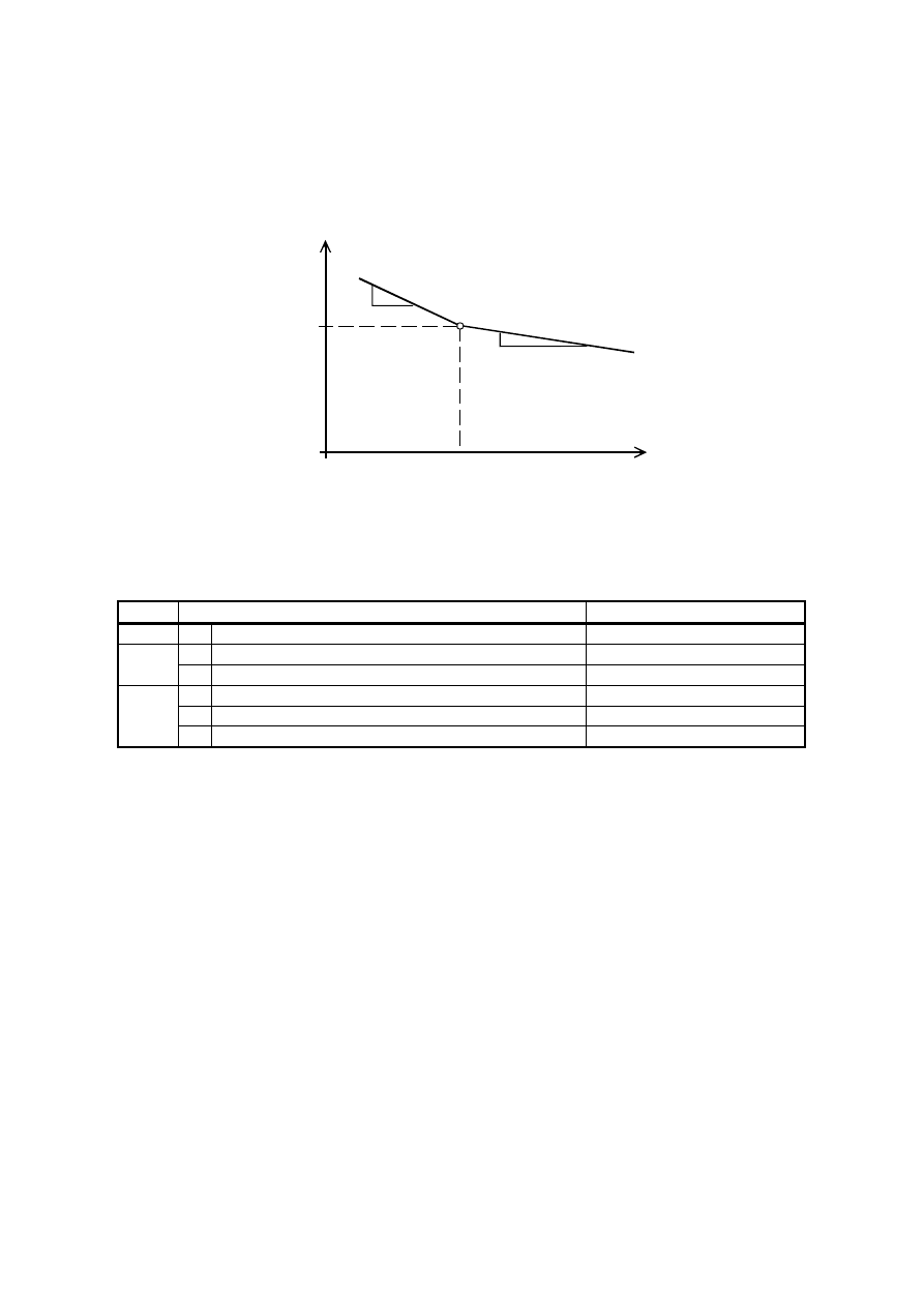
(1)
In the absence of the tests described in 9.1(2) above, fatigue strength curves and detail categories may
be obtained from Figure 9.1 and Table 9.1, respectively.
Figure 9.1: Fatigue strength curves for tension components
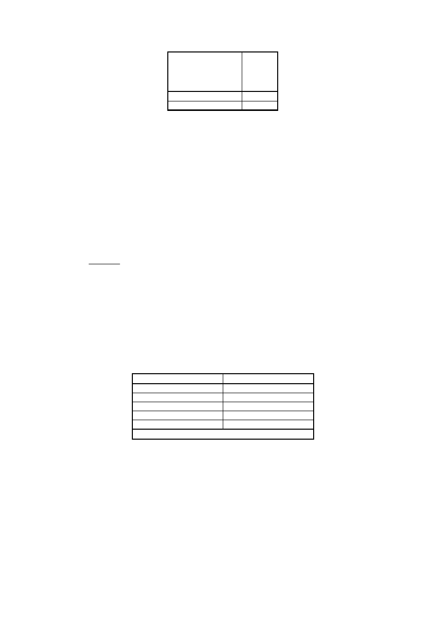
Table 9.1: Detail categories for fatigue strength according to EN 1993-1-9
Group Tension
components Detail
category
ǻı
c
[N/mm²]
A 1
Prestressing
bars
105
2
Fully locked coil rope with metal or resin socketing
150
B
3
Spiral strands with metal or resin socketing
150
4
Parallel wire strands with epoxy socketing
160
5
Bundle of parallel strands
160
C
6
Bundle of parallel wires
160
NOTE: The detail categories in Table 9.1 refer to exposure classes 3 and 4 according to Table 2.1. For axial and
lateral fatigue actions (exposure class 5 according to Table 2.1) additional protective measures are required in
order to minimise bending stresses.
(2)
The categories given in (1) are only valid when the following conditions apply:
a) cables with sockets comply with the basic requirements in Annex A;
b) the design of cables, saddles and clamps complies with 6;
c) large aerodynamic oscillations of cables are prevented, see 8;
d) adequate protection against corrosion is provided, see 4.
(3)
For fatigue assessments see EN 1993-1-9.
2×10
6
log
Δ
σ
R
1
6
4
1
log N
R
Δ
σ
c
BS EN 1993-1-11: 2006
Licensed copy: BSI USER 06 Document Controller, Midmac Contracting Co. W.L.L, Version correct as of 05/06/2011 15:07, (c) BSI

EN 1993-1-11: 2006 (E)
27
Annex A [informative] – Product requirements for tension components
A.1 Scope
(1)
This annex gives the product requirements for tension components and their terminations to be used
for buildings and civil engineering works.
(2)
The requirements are based on the specific use of the prefabricated tension component including
environmental and loading conditions.
(3)
The following types of prefabricated tension components are covered:
–
Group A: tension rod systems, bars;
–
Group C: bundle of parallel wires, bundle of bars, bundle of parallel strands.
A.2 Basic requirements
(1)
Tension components should comply with the following criteria:
1. strength and ductility of the cable system and its terminations;
2. fatigue resistance due to axial load fluctuation, bending stresses, angular deviations caused by catenary
effects, wind forces and erection imperfections;
3. stable condition of axial and flexural stiffness of the cable system (e.g. by guaranteed pre-stretching);
4. protection of cable and anchorages against corrosion;
5. resistance to fretting at any contact between steel parts.
(2)
Terminations and anchorages of the tension components should be designed such that:
1. the ultimate resistance of the tension component would be reached before any yielding or other permanent
deformation of the anchoring or any bearing elements would occur;
2. their fatigue resistance exceeds that of the components;
3. facilities for adjustment of the component length are provided to meet the requirements for preload,
geometrical tolerances etc.;
4. sufficient articulation is provided in the anchorage to cater for manufacturing and erection imperfections;
5. the tension components can be replaced.
(3)
The above requirements should be met by:
–
appropriate choice of materials for wires, strands, steels and protective coatings;
–
choice of the form of construction in respect of strength, stiffness, ductility, durability and robustness for
manufacturing, transport, handling and installation;
–
quality control of accurate fitting of the end termination to ensure the correct alignment of tension
component in service.
(4)
The compliance of the above requirements should be verified by testing as part of an appropriate
quality management system.
A.3 Materials
(1)
All materials used should comply with the relevant European technical specifications.
(2)
The suitability of the corrosion protection system including the durability of fillers and protection
materials should be proved by appropriate testing.
BS EN 1993-1-11: 2006
Licensed copy: BSI USER 06 Document Controller, Midmac Contracting Co. W.L.L, Version correct as of 05/06/2011 15:07, (c) BSI
EN 1993-1-11: 2006 (E)
28
NOTE: The testing may prove the following:
–
protection against aggressive agents (chemicals, stress corrosion cracking, UV);
–
water tightness (flexibility and durability when cable bends);
–
durability of colour (if required).
A.4 Requirements for tests
A.4.1 General
(1)
The following tests on wire, strands, bars and complete tension components should ensure that they
perform as required.
(2)
F
ke
and F
uke
(see 6.2) should be determined in a static tension test. If required (e.g. for cutting to length
(see 3.4) and structural analysis (see 5)) the test should follow the predicted stress profile of the cable in the
structure for measuring all relevant data.
(3)
To determine the fatigue strength curve, where required, a representative number of axial tests should
be carried out at
ı
sup
= 0,45
ı
uk
(see 7.2(2)) with different values of
ΔF, see Table A.4.1.
NOTE: The fatigue testing should be carried out under load control and not under extension control.
Table A.4.1: Testing requirements for fatigue
Type of test
Fatigue loading before fracture test
1
axial test
(class 3 and 4)
ı
sup
= 0,45
ı
uk
ǻı according to ǻı
c
given in Table 9.1
ǻĮ = 0
n =
2
×10
6
cycles
2
axial and
flexural test
(class 5)
ı
sup
= 0,45
ı
uk
ǻı according to ǻı
c
given in Table 9.1
ǻĮ = 0 – 10 milli radians
(0 – 0,7 degrees)
n =
2
×10
6
cycles
(4)
If the tension component is to be subjected to fatigue loading and the fatigue resistance is verified
according to 9.2(2) at least one test for each diameter of the component should be undertaken. It should be
checked that in an axial test with
ı
sup
= 0,45
ı
uk
and
Δı = 1,25 Δı
c
(see Table 9.1) the number of broken
wires after 2
⋅10
6
cycles is less than 2% of the total. No failure should occur in the anchorage material or in
any component of the anchorage during the fatigue tests. No failure is acceptable for bars.
(5)
If the round-out radius at the entrance of the cable in the socket is less than 30d (see Figure 6.1) the
tests as described in (2) and (3) should be undertaken with
Δ
α
being governed by the round-out radius.
(6)
After fatigue loading, the test specimen should be loaded to fracture and should develop a minimum
tensile force equal to 92% of the actual tensile strength of the cable or 95% of the minimum ultimate tensile
strength of the cable, whichever is greater. The strain under this load should not be less than 1,5%.
(7)
Fatigue tests in accordance with EN 10138 should be carried out on single strands, wires or bars taken
from samples of each manufactured length of tension components.
BS EN 1993-1-11: 2006
Licensed copy: BSI USER 06 Document Controller, Midmac Contracting Co. W.L.L, Version correct as of 05/06/2011 15:07, (c) BSI

EN 1993-1-11: 2006 (E)
29
A.4.2 Main tension elements
A.4.2.1 Wires
(1)
Wires coated in zinc or zinc alloy should be tested in an approved testing machine.
A.4.2.2 Strands
(1)
Tests should be carried out for tensile strength, 0,1% proof strength and elongation according to
EN 10138.
A.4.2.3 Bars
(1)
Tests should be carried out for tensile strength, 0,1% proof strength and elongation according to
EN 10138.
A.4.3 Strands and complete cables
(1)
If different sizes of one type of strand or ropes are used at least 3 representative tests should be carried
out. Cables should be tested with all load-bearing components attached to them and the test load should be
applied in the same way as in the structure.
A.4.4 Coefficient of friction
(1)
If the coefficient of friction between the strands and saddles, clamps etc. is determined by testing the
following should be taken into account:
–
the effects of axial loads on the diameter of the strands;
–
the creep due to transverse preloading (on filler material and zinc coating).
(2)
In the evaluation of the test results account should be taken of the fact, that friction can be either
beneficial or adverse depending on the effect being considered.
A.4.5 Corrosion protection
A.4.5.1 Waterproofing
(1)
The durability of the cable system should be verified using “accelerated ageing” in which the cycles of
axial loads and bending and temperatures can be simulated. The test should be carried out for a
representative section of the complete lower end of the cable including anchoring devices, stay pipe etc.
NOTE: Details for tests may be given in the National Annex.
A.4.5.2 Corrosion protection barriers
NOTE: Details for tests, e.g. salt fog tests, may be given in the National Annex.
BS EN 1993-1-11: 2006
Licensed copy: BSI USER 06 Document Controller, Midmac Contracting Co. W.L.L, Version correct as of 05/06/2011 15:07, (c) BSI

EN 1993-1-11: 2006 (E)
30
Annex B [informative] – Transport, storage, handling
(1)
Spiral strands and fully locked coil cables are supplied in either coils or on reels.
(2)
To keep the out cover wires in lay the minimum diameter of the reel should not be less than 30 times
the rope diameter of fully locked coil ropes, 24 times the rope diameter of spiral strand ropes and 16 times
the diameter of strand ropes.
NOTE: The minimum diameter depends on the protection system, storage time and temperature. Caution
should be taken when unreeling at temperatures below 5 °C.
(3)
If cables are stored in coils each coil should be properly ventilated (no direct ground contact) to
prevent any formation of white blister which may be caused by condensation or moisture.
(4)
Cables should be handled with utmost care during installation. Coils require a turntable for horizontal
unreeling.
(5)
Cables should not:
–
have their serving removed before they have been installed;
–
be bent through a radius smaller than 30
× cable diameter;
–
be pulled across sharp edges;
–
be neither twisted or untwisted (observe cable marking line).
(6)
Tension components should be monitored and inspected during working life for deviations to design
conditions, corrosion and damage.
NOTE: The National Annex may give further guidance on monitoring and inspections.
BS EN 1993-1-11: 2006
Licensed copy: BSI USER 06 Document Controller, Midmac Contracting Co. W.L.L, Version correct as of 05/06/2011 15:07, (c) BSI
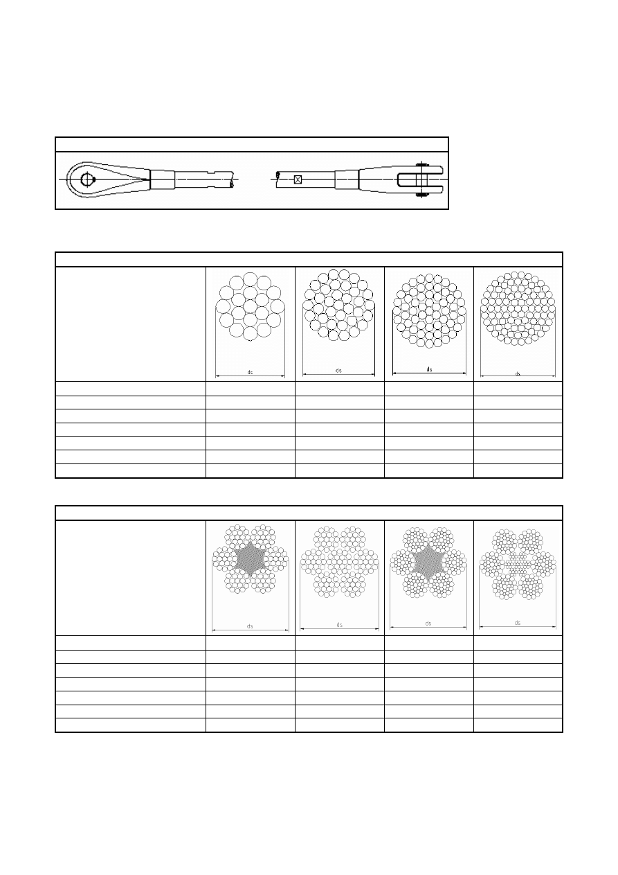
EN 1993-1-11: 2006 (E)
31
Annex C [informative] – Glossary
NOTE: See EN 12385, Part 2.
C.1 Products Group A
Tension rod system
C.2 Products Group B
Spiral strand rope
Construction
1
× 19
1
× 37
1
× 61
1
× 91
Diameter d
s
[mm]
3 to 14
6 to 36
20 to 40
30 to 52
Strand 1
1
1
1
Wire per strand
19
37
61
91
Outer wire per strand
12
18
24
30
Nominal metallic area factor C 0,6
0,59
0,58
0,58
Breaking force factor K 0,525 0,52 0,51 0,51
Strand rope
Construction
6
× 19 - CF
6
× 19 - CWS
6
× 36WS - CF 6 × 36 WS- CWR
Diameter d
s
[mm]
6 to 40
6 to 40
6 to 40
6 to 40
Strand 6
6
6
6
Wire per strand
18
18
36
36
Outer wire per strand
12
12
14
14
Nominal metallic area factor C 0,357
0,414
0,393
0,455
Breaking force factor K 0,307
0,332
0,329
0,355
BS EN 1993-1-11: 2006
Licensed copy: BSI USER 06 Document Controller, Midmac Contracting Co. W.L.L, Version correct as of 05/06/2011 15:07, (c) BSI
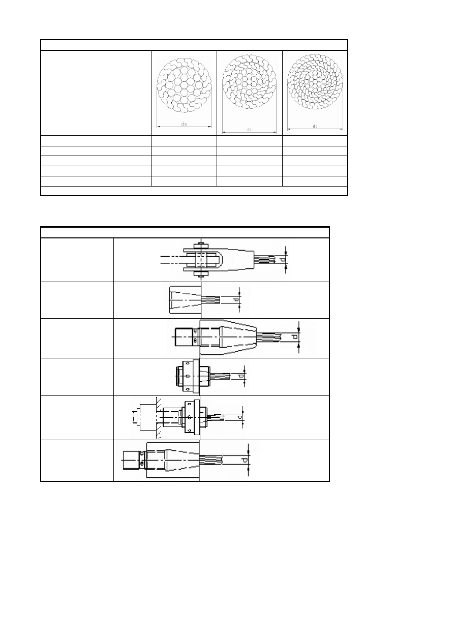
EN 1993-1-11: 2006 (E)
32
Fully locked coil rope
Construction
1 layer Z-wires
2 layer Z-wires
≥ 3 layer Z-wires
Diameter d
s
[mm]
20 to 40
25 to 50
40 to 180
Tolerance for d
s
+5% +5% +5%
Nominal metallic area factor C 0,636
0,660
0,700
Breaking force factor K 0,585
0,607
0,643
NOTE: Nominal metallic area factor and breaking force factor acc. EN 12385-2.
C.3 Wire rope end connectors
Wire rope end connectors - Metal or resin socketing acc. EN 13411-4
Open spelter socket
Cylindrical socket
Conical socket with
internal thread and
tension rod
Cylindrical socket
with external thread
and nut
Cylindrical socket
with internal and
external thread and
nut
Cylindrical socket
with internal thread
and tension rod
BS EN 1993-1-11: 2006
Licensed copy: BSI USER 06 Document Controller, Midmac Contracting Co. W.L.L, Version correct as of 05/06/2011 15:07, (c) BSI
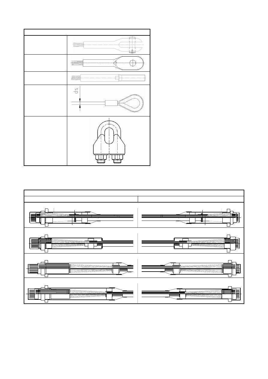
EN 1993-1-11: 2006 (E)
33
Wire rope end connectors swaged
Open swaged
socket
Closed swaged
socket
Swaged fitting
with thread
Thimble with
swaged aluminium
ferrule acc.
EN 13411-3
U-bolt grip acc.
EN 13411-5
C.4 Product Group C
Bare strands, PE- or epoxy-coated strands
Live end anchorage
Live end anchorage
Anchorage with wedges and postgrouted bond socket – bare strands, PE- or epoxy-coated strands
Anchorage with wedges and sealing plates – PE-coated strands
Anchorage with wedges and pregrouted pipe – PE-coated strands
Anchorage with wedges and wax filled transition pipe – PE-coated strands
BS EN 1993-1-11: 2006
Licensed copy: BSI USER 06 Document Controller, Midmac Contracting Co. W.L.L, Version correct as of 05/06/2011 15:07, (c) BSI
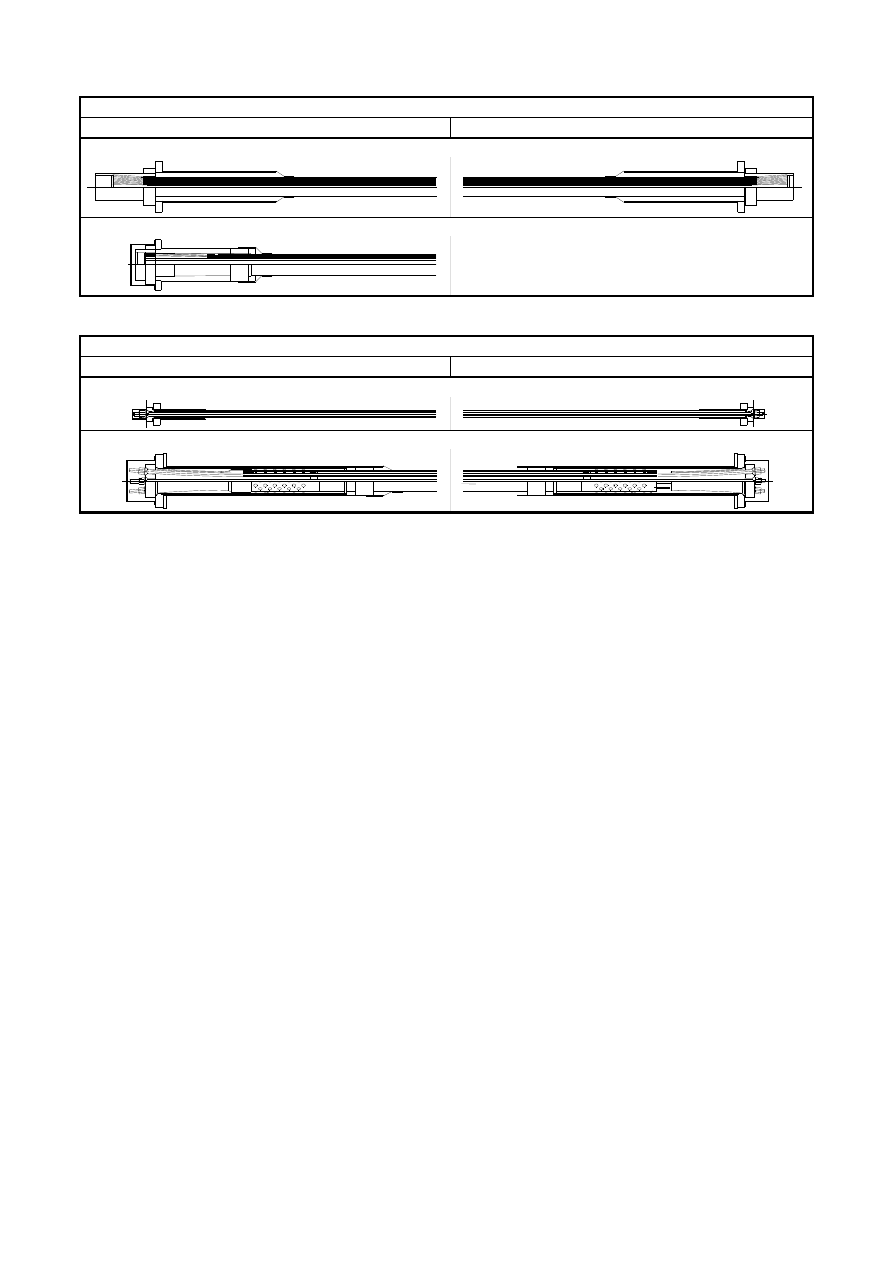
EN 1993-1-11: 2006 (E)
34
Wires
Live end anchorage
Live end anchorage
Anchorage with wires and compound filled socket
Anchorage with wires and button heads filled with epoxy resin
Bars
Live end anchorage
Live end anchorage
Anchorage with single bar
Anchorage with multiple bars and steel sheathing, grouted
BS EN 1993-1-11: 2006
Licensed copy: BSI USER 06 Document Controller, Midmac Contracting Co. W.L.L, Version correct as of 05/06/2011 15:07, (c) BSI

blank
Licensed copy: BSI USER 06 Document Controller, Midmac Contracting Co. W.L.L, Version correct as of 05/06/2011 15:07, (c) BSI

D
<$E/0
!#< &
6&%**?6&
')**+,-.,/0010,,8
23)**+,-.,/0014,,8
";
!
""
"#""
""$
%"
"""
&'(
)**+,-.,/0010,,,23()**+,-.,/0014*,,
""56
"
7&
!"'()**+,-.,/0010,,823()**+,-.,/001
4,,8"(9":";
"%(;;";
&
""&
$
"&
6'<3
="
!"!'(
)**+,-.,/001488823()**+,-.,/0014,*/"(9"
""#"
2
>"?"'()**+,-.,
/0014,,.23()**+,-.,/0014,,8"(""9"
"
7(;;";76
2"(;;
"
!&
&@3
"!&A5?80//3"
&"""
"B&&B
""
'&""&
"&@&
""
""
A"!6>
'()**+,-.,/0014,4,"(9"
BS EN
1993-1-11:2006
Licensed copy: BSI USER 06 Document Controller, Midmac Contracting Co. W.L.L, Version correct as of 05/06/2011 15:07, (c) BSI
Wyszukiwarka
Podobne podstrony:
Eurocode 3 Part 1 11 2005 UK NA Design of Steel Structures Design of Structures with Tension Com
Eurocode 6 Part 2 1996 2006 Design of Masonry Structures Design Considerations, Selection of Mat
Eurocode 6 Part 2 1996 2006 Design of Masonry Structures Design Considerations, Selection of Mat
Eurocode 6 Part 3 1996 2006 Design of Masonry Structures Simplified Calculation Methods for Maso
Eurocode 8 Part 4 1998 2006 Design of tructures for Earthquake Resistance Silos, Tanks and Pipe
Eurocode 3 Part 1 12 2007 Design of Steel Structures Additional Rules for the Extension of EN 199
Eurocode 6 Part 1 2 1996 2005 Design of Masonry Structures General Rules Structural Fire Design
Eurocode 8 Part 1 1998 2004 Design of Structures for Earthquake Resistance General Rules Seism
Eurocode 8 Part 5 1998 2004 Design of Structures for Earthquake Resistance Foundations, Retaini
Eurocode 8 Part 6 1998 2005 Design of Structures for Earthquake Resistance Towers, Masts and Ch
Eurocode 8 Part 5 1998 2004 Design of Structures for Earthquake Resistance Foundations, Retaini
Eurocode 5 Part 1 2 1995 2004 Design of Timber Structures General Structural Fire Design UK Ann
Eurocode 9 Part 1 3 1999 2007 Design of Aluminium Structures Structures Susceptible to Fatigue
Eurocode 5 Part 2 1995 2004 Design of timber structures Bridges
Eurocode 8 Part 6 1998 2005 Design of Structures for Earthquake Resistance Towers, Masts and Ch
Eurocode 9 Part 1 2 1999 2007 Design of Aluminium Structures Structural Fire Design UK NA
Eurocode 6 Part 1 1 1996 2005 Design of Masonry Structures General Rules for Reinforced and Unre
Eurocode 9 Part 1 4 1999 2007 Design of Aluminium Structures Cold formed Structural Sheeting UK
Eurocode 3 Part 1 11 Pren 1993 1 11 (Eng)
więcej podobnych podstron