
BRITISH STANDARD
BS EN
1993-1-9:2005
Eurocode 3: Design of
steel structures —
Part 1-9: Fatigue
ICS 91.010.30
12&23<,1*:,7+287%6,3(50,66,21(;&(37$63(50,77('%<&23<5,*+7/$:
Incorporating
corrigenda
December 2005,
September 2006
and April 2009
Licensed copy: BSI USER 06 Document Controller, Midmac Contracting Co. W.L.L, Version correct as of 05/06/2011 14:51, (c) BSI

BS EN 1993-1-9:2005
This British Standard, was
published under the authority
of the Standards Policy and
Strategy Committee on
18 May 2005
© BSI 2010
ISBN 978 0 580 66400 7
National Foreword
This British Standard is the UK implementation of EN 1993-1-9:2005,
incorporating corrigenda December 2005 and April 2009. It supersedes
DD ENV 1993-1-1:1992, which is withdrawn.
The start and finish of text introduced or altered by corrigendum is indicated
in the text by tags. Tags indicating changes to CEN text carry the number of
the CEN corrigendum. For example, text altered by December 2005
corrigendum is indicated by
ˆ‰.
The structural Eurocodes are divided into packages by grouping Eurocodes for
each of the main materials: concrete, steel, composite concrete and steel,
timber, masonry and aluminium; this is to enable a common date of
withdrawal (DOW) for all the relevant parts that are needed for a particular
design. The conflicting national standards will be withdrawn at the end of the
co-existence period, after all the EN Eurocodes of a package are available.
Following publication of the EN, there is a period allowed for national
calibration during which the National Annex is issued, followed by a
co-existence period of a maximum three years. During the co-existence period
Member States are encouraged to adapt their national provisions. At the end
of this co-existence period, the conflicting parts of national standard(s) will be
withdrawn.
In the UK, the primary corresponding national standards are:
BS 5400-10:1980, Steel, concrete and composite bridges. Code of practice for
fatigue
BS 7608:1993, Code of practice for fatigue design and assessment of steel
structures
BS EN 1993-1-9 partially supersedes BS 5400-10, which will be withdrawn by
March 2010. BS 7608 is being retained as it covers steel structures outside the
scope of the Eurocode standards. It is, however, being revised to remove
conflicting material, in the meantime the UK committee advises users to read
BS 7608 in conjunction with this standard.
Amendments/corrigenda issued since publication
Amd. No.
Date
Comments
16292
Corrigendum
No.1
June 2006
Implementation of CEN corrigendum
December 2005
16570
Corrigendum
No.2
29 September
2006
Revision of national foreword and
supersession details
28 February
2010
Implementation of CEN corrigendum
April 2009
Licensed copy: BSI USER 06 Document Controller, Midmac Contracting Co. W.L.L, Version correct as of 05/06/2011 14:51, (c) BSI

The UK participation in its preparation was entrusted by Technical Committee
B/525, Building and civil engineering structures, to Subcommittee B/525/31,
Structural use of steel.
A list of organizations represented on this subcommittee can be obtained on
request to its secretary.
Where a normative part of this EN allows for a choice to be made at the
national level, the range and possible choice will be given in the normative text
as Recommended Values, and a note will qualify it as a Nationally Determined
Parameter (NDP). NDPs can be a specific value for a factor, a specific level or
class, a particular method or a particular application rule if several are
proposed in the EN.
To enable EN 1993-1-9 to be used in the UK, the NDPs have been published in
a National Annex, which has been issued separately by BSI.
This publication does not purport to include all the necessary provisions of a
contract. Users are responsible for its correct application.
Compliance with a British Standard cannot confer immunity from
legal obligations.
BS EN 1993-1-9:2005
ii
Licensed copy: BSI USER 06 Document Controller, Midmac Contracting Co. W.L.L, Version correct as of 05/06/2011 14:51, (c) BSI

This page deliberately set blank
Licensed copy: BSI USER 06 Document Controller, Midmac Contracting Co. W.L.L, Version correct as of 05/06/2011 14:51, (c) BSI

EUROPEAN STANDARD
NORME EUROPÉENNE
EUROPÄISCHE NORM
EN
1993-1-9
May
2005
ICS 91.010.30
Supersedes ENV 1993-1-1:1992
Incorporating
corrigenda
December 2005 and
2009
April
English version
Eurocode 3: Design of steel structures - Part 1-9: Fatigue
Eurocode 3: Calcul des structures en acier - Partie 1-9:
Fatigue
Eurocode 3: Bemessung und Konstruktion von Stahlbauten
- Teil 1-9: Ermüdung
This European Standard was approved by CEN on 23 April 2004.
CEN members are bound to comply with the CEN/CENELEC Internal Regulations which stipulate the conditions for giving this European
Standard the status of a national standard without any alteration. Up-to-date lists and bibliographical references concerning such national
standards may be obtained on application to the Central Secretariat or to any CEN member.
This European Standard exists in three official versions (English, French, German). A version in any other language made by translation
under the responsibility of a CEN member into its own language and notified to the Central Secretariat has the same status as the official
versions.
CEN members are the national standards bodies of Austria, Belgium, Cyprus, Czech Republic, Denmark, Estonia, Finland, France,
Germany, Greece, Hungary, Iceland, Ireland, Italy, Latvia, Lithuania, Luxembourg, Malta, Netherlands, Norway, Poland, Portugal, Slovakia,
Slovenia, Spain, Sweden, Switzerland and United Kingdom.
EUROPEAN COMMITTEE FOR STANDARDIZATION
C O M I T É E U R O P É E N D E N O R M A L I S A T I O N
E U R O P Ä I S C H E S K O M I T E E F Ü R N O R M U N G
Management Centre: rue de Stassart, 36 B-1050 Brussels
© 2005 CEN
All rights of exploitation in any form and by any means reserved
worldwide for CEN national Members.
Ref. No. EN 1993-1-9:2005: E
Licensed copy: BSI USER 06 Document Controller, Midmac Contracting Co. W.L.L, Version correct as of 05/06/2011 14:51, (c) BSI

EN 1993-1-9 : 2005 (E)
2
Contents
Page
1
General ................................................................................................................................................. 6
1.1
Scope ................................................................................................................................................. 6
1.2
Normative references......................................................................................................................... 6
1.3
Terms and definitions ........................................................................................................................ 6
1.4
Symbols ............................................................................................................................................. 9
2
Basic requirements and methods ....................................................................................................... 9
3
Assessment methods ...........................................................................................................................10
4
Stresses from fatigue actions .............................................................................................................11
5
Calculation of stresses ........................................................................................................................12
6
Calculation of stress ranges ...............................................................................................................13
6.1
General .............................................................................................................................................13
6.2
Design value of nominal stress range ...............................................................................................13
6.3
Design value of modified nominal stress range................................................................................14
6.4
Design value of stress range for welded joints of hollow sections ...................................................14
6.5
Design value of stress range for geometrical (hot spot) stress .........................................................14
7
Fatigue strength ..................................................................................................................................14
7.1
General .............................................................................................................................................14
7.2
Fatigue strength modifications .........................................................................................................17
8
Fatigue verification.............................................................................................................................18
Annex A [normative] – Determination of fatigue load parameters and verification formats .................30
Annex B [normative] – Fatigue resistance using the geometric (hot spot) stress method........................33
BS EN 1993-1-9 : 2005
Licensed copy: BSI USER 06 Document Controller, Midmac Contracting Co. W.L.L, Version correct as of 05/06/2011 14:51, (c) BSI

EN 1993-1-9 : 2005 (E)
3
Foreword
This European Standard EN 1993, Eurocode 3: Design of steel structures, has been prepared by Technical
Committee CEN/TC250 « Structural Eurocodes », the Secretariat of which is held by BSI. CEN/TC250 is
responsible for all Structural Eurocodes.
This European Standard shall be given the status of a National Standard, either by publication of an identical
text or by endorsement, at the latest by
November 2005, and conflicting National Standards shall be withdrawn
at latest by March 2010.
This Eurocode supersedes ENV
1993-1-1.
According to the CEN-CENELEC Internal Regulations, the National Standard Organizations of the
following countries are bound to implement these European Standard: Austria, Belgium, Cyprus, Czech
Republic, Denmark, Estonia, Finland, France, Germany, Greece, Hungary, Iceland, Ireland, Italy, Latvia,
Lithuania, Luxembourg, Malta, Netherlands, Norway, Poland, Portugal, Slovakia, Slovenia, Spain, Sweden,
Switzerland and United Kingdom.
Background to the Eurocode programme
In 1975, the Commission of the European Community decided on an action programme in the field of
construction, based on article 95 of the Treaty. The objective of the programme was the elimination of
technical obstacles to trade and the harmonization of technical specifications.
Within this action programme, the Commission took the initiative to establish a set of harmonized technical
rules for the design of construction works which, in a first stage, would serve as an alternative to the national
rules in force in the Member States and, ultimately, would replace them.
For fifteen years, the Commission, with the help of a Steering Committee with Representatives of Member
States, conducted the development of the Eurocodes programme, which led to the first generation of
European codes in the 1980s.
In 1989, the Commission and the Member States of the EU and EFTA decided, on the basis of an agreement
1
between the Commission and CEN, to transfer the preparation and the publication of the Eurocodes to CEN
through a series of Mandates, in order to provide them with a future status of European Standard (EN). This
links de facto the Eurocodes with the provisions of all the Council’s Directives and/or Commission’s
Decisions dealing with European standards (e.g. the Council Directive 89/106/EEC on construction products
- CPD - and Council Directives 93/37/EEC, 92/50/EEC and 89/440/EEC on public works and services and
equivalent EFTA Directives initiated in pursuit of setting up the internal market).
The Structural Eurocode programme comprises the following standards generally consisting of a number of
Parts:
EN 1990
Eurocode 0:
Basis of Structural Design
EN 1991
Eurocode 1:
Actions on structures
EN 1992
Eurocode 2:
Design of concrete structures
EN 1993
Eurocode 3:
Design of steel structures
EN 1994
Eurocode 4:
Design of composite steel and concrete structures
EN 1995
Eurocode 5:
Design of timber structures
EN 1996
Eurocode 6:
Design of masonry structures
EN 1997
Eurocode 7:
Geotechnical design
EN 1998
Eurocode 8:
Design of structures for earthquake resistance
EN 1999
Eurocode 9:
Design of aluminium structures
1
Agreement between the Commission of the European Communities and the European Committee for Standardisation (CEN)
concerning the work on EUROCODES for the design of building and civil engineering works (BC/CEN/03/89).
BS EN 1993-1-9 : 2005
Licensed copy: BSI USER 06 Document Controller, Midmac Contracting Co. W.L.L, Version correct as of 05/06/2011 14:51, (c) BSI

EN 1993-1-9 : 2005 (E)
4
Eurocode standards recognize the responsibility of regulatory authorities in each Member State and have
safeguarded their right to determine values related to regulatory safety matters at national level where these
continue to vary from State to State.
Status and field of application of Eurocodes
The Member States of the EU and EFTA recognize that Eurocodes serve as reference documents for the
following purposes :
– as a means to prove compliance of building and civil engineering works with the essential requirements
of Council Directive 89/106/EEC, particularly Essential Requirement N°1 – Mechanical resistance and
stability – and Essential Requirement N°2 – Safety in case of fire;
– as a basis for specifying contracts for construction works and related engineering services;
– as a framework for drawing up harmonized technical specifications for construction products (ENs and
ETAs)
The Eurocodes, as far as they concern the construction works themselves, have a direct relationship with the
Interpretative Documents
2
referred to in Article 12 of the CPD, although they are of a different nature from
harmonized product standards
3
. Therefore, technical aspects arising from the Eurocodes work need to be
adequately considered by CEN Technical Committees and/or EOTA Working Groups working on product
standards with a view to achieving full compatibility of these technical specifications with the Eurocodes.
The Eurocode standards provide common structural design rules for everyday use for the design of whole
structures and component products of both a traditional and an innovative nature. Unusual forms of
construction or design conditions are not specifically covered and additional expert consideration will be
required by the designer in such cases.
National Standards implementing Eurocodes
The National Standards implementing Eurocodes will comprise the full text of the Eurocode (including any
annexes), as published by CEN, which may be preceded by a National title page and National foreword, and
may be followed by a National annex.
The National annex may only contain information on those parameters which are left open in the Eurocode
for national choice, known as Nationally Determined Parameters, to be used for the design of buildings and
civil engineering works to be constructed in the country concerned, i.e. :
– values and/or classes where alternatives are given in the Eurocode,
– values to be used where a symbol only is given in the Eurocode,
– country specific data (geographical, climatic, etc.), e.g. snow map,
– the procedure to be used where alternative procedures are given in the Eurocode.
It may contain
– decisions on the application of informative annexes,
– references to non-contradictory complementary information to assist the user to apply the Eurocode.
2
According to Art. 3.3 of the CPD, the essential requirements (ERs) shall be given concrete form in interpretative documents for the
creation of the necessary links between the essential requirements and the mandates for harmonized ENs and ETAGs/ETAs.
3
According to Art. 12 of the CPD the interpretative documents shall :
a)
give concrete form to the essential requirements by harmonizing the terminology and the technical bases and indicating classes or levels for each
requirement where necessary ;
b)
indicate methods of correlating these classes or levels of requirement with the technical specifications, e.g. methods of calculation and of proof,
technical rules for project design, etc. ;
c) serve as a reference for the establishment of harmonized standards and guidelines for European technical approvals.
The Eurocodes, de facto, play a similar role in the field of the ER 1 and a part of ER 2.
BS EN 1993-1-9 : 2005
Licensed copy: BSI USER 06 Document Controller, Midmac Contracting Co. W.L.L, Version correct as of 05/06/2011 14:51, (c) BSI

EN 1993-1-9 : 2005 (E)
5
Links between Eurocodes and harmonized technical specifications (ENs and ETAs) for
products
There is a need for consistency between the harmonized technical specifications for construction products
and the technical rules for works
4
. Furthermore, all the information accompanying the CE Marking of the
construction products which refer to Eurocodes should clearly mention which Nationally Determined
Parameters have been taken into account.
National annex for EN 1993-1-9
This standard gives alternative procedures, values and recommendations with notes indicating where national
choices may have to be made. The National Standard implementing EN 1993-1-9 should have a National
Annex containing all Nationally Determined Parameters for the design of steel structures to be constructed in
the relevant country.
National choice is allowed in EN 1993-1-9 through:
–
1.1(2)
–
2(2)
–
2(4)
–
3(2)
–
3(7)
–
5(2)
–
6.1(1)
–
6.2(2)
–
7.1(3)
–
7.1(5)
–
8(4)
4
see Art.3.3 and Art.12 of the CPD, as well as clauses 4.2
, 4.3.1, 4.3.2 and 5.2 of ID 1
.
BS EN 1993-1-9 : 2005
Licensed copy: BSI USER 06 Document Controller, Midmac Contracting Co. W.L.L, Version correct as of 05/06/2011 14:51, (c) BSI

EN 1993-1-9 : 2005 (E)
6
1 General
1.1 Scope
(1)
EN 1993-1-9 gives methods for the assessment of fatigue resistance of members, connections and
joints subjected to fatigue loading.
(2)
These methods are derived from fatigue tests with large scale specimens, that include effects of
geometrical and structural imperfections from material production and execution (e.g. the effects of
tolerances and residual stresses from welding).
NOTE 1 For tolerances see EN 1090. The choice of the execution standard may be given in the
National Annex, until such time as EN 1090 is published.
NOTE 2 The National Annex may give supplementary information on inspection requirements
during fabrication.
(3)
The rules are applicable to structures where execution conforms with EN 1090.
NOTE Where appropriate, supplementary requirements are indicated in the detail category tables.
(4)
The assessment methods given in this part are applicable to all grades of structural steels, stainless
steels and unprotected weathering steels except where noted otherwise in the detail category tables. This part
only applies to materials which conform to the toughness requirements of EN 1993-1-10.
(5)
Fatigue assessment methods other than the
'V
R
-N methods as the notch strain method or fracture
mechanics methods are not covered by this part.
(6)
Post fabrication treatments to improve the fatigue strength other than stress relief are not covered in
this part.
(7) The fatigue strengths given in this part apply to structures operating under normal atmospheric
conditions and with sufficient corrosion protection and regular maintenance. The effect of seawater corrosion
is not covered. Microstructural damage from high temperature (> 150 °C) is not covered.
1.2 Normative
references
This European Standard incorporates by dated or undated reference, provisions from other publications.
These normative references are cited at the appropriate places in the text and the publications are listed
hereafter. For dated references, subsequent amendments to or revisions of any of these publications apply to
this European Standard only when incorporated in it by amendment or revision. For undated references the
latest edition of the publication referred to applies (including amendments).
The following general standards are referred to in this standard.
EN 1090
Execution of steel structures – Technical requirements
EN 1990
Basis of structural design
EN 1991
Actions on structures
EN 1993
Design of Steel Structures
EN 1994-2 Design of Composite Steel and Concrete Structures: Part 2: Bridges
1.3 Terms and definitions
(1)
For the purpose of this European Standard the following terms and definitions apply.
BS EN 1993-1-9 : 2005
Licensed copy: BSI USER 06 Document Controller, Midmac Contracting Co. W.L.L, Version correct as of 05/06/2011 14:51, (c) BSI

EN 1993-1-9 : 2005 (E)
7
1.3.1 General
1.3.1.1
fatigue
The process of initiation and propagation of cracks through a structural part due to action of fluctuating
stress.
1.3.1.2
nominal stress
A stress in the parent material or in a weld adjacent to a potential crack location calculated in accordance
with elastic theory excluding all stress concentration effects.
NOTE The nominal stress as specified in this part can be a direct stress, a shear stress, a principal
stress or an equivalent stress.
1.3.1.3
modified nominal stress
A nominal stress multiplied by an appropriate stress concentration factor k
f
, to allow for a geometric
discontinuity that has not been taken into account in the classification of a particular constructional detail.
1.3.1.4
geometric stress
hot spot stress
The maximum principal stress in the parent material adjacent to the weld toe, taking into account stress
concentration effects due to the overall geometry of a particular constructional detail.
NOTE Local stress concentration effects e.g. from the weld profile shape (which is already included
in the detail categories in Annex B) need not be considered.
1.3.1.5
residual stress
Residual stress is a permanent state of stress in a structure that is in static equilibrium and is independent of
any applied action. Residual stresses can arise from rolling stresses, cutting processes, welding shrinkage or
lack of fit between members or from any loading event that causes yielding of part of the structure.
1.3.2 Fatigue loading parameters
1.3.2.1
loading event
A defined loading sequence applied to the structure and giving rise to a stress history, which is normally
repeated a defined number of times in the life of the structure.
1.3.2.2
stress history
A record or a calculation of the stress variation at a particular point in a structure during a loading event.
1.3.2.3
rainflow method
Particular cycle counting method of producing a stress-range spectrum from a given stress history.
1.3.2.4
reservoir method
Particular cycle counting method of producing a stress-range spectrum from a given stress history.
NOTE For the mathematical determination see annex A.
1.3.2.5
stress range
The algebraic difference between the two extremes of a particular stress cycle derived from a stress history.
BS EN 1993-1-9 : 2005
Licensed copy: BSI USER 06 Document Controller, Midmac Contracting Co. W.L.L, Version correct as of 05/06/2011 14:51, (c) BSI

EN 1993-1-9 : 2005 (E)
8
1.3.2.6
stress-range spectrum
Histogram of the number of occurrences for all stress ranges of different magnitudes recorded or calculated
for a particular loading event.
1.3.2.7
design spectrum
The total of all stress-range spectra in the design life of a structure relevant to the fatigue assessment.
1.3.2.8
design life
The reference period of time for which a structure is required to perform safely with an acceptable
probability that failure by fatigue cracking will not occur.
1.3.2.9
fatigue life
The predicted period of time to cause fatigue failure under the application of the design spectrum.
1.3.2.10
Miner's summation
A linear cumulative damage calculation based on the Palmgren-Miner rule.
1.3.2.11
equivalent constant amplitude stress range
The constant-amplitude stress range that would result in the same fatigue life as for the design spectrum,
when the comparison is based on a Miner's summation.
NOTE For the mathematical determination see Annex A.
1.3.2.12
fatigue loading
A set of action parameters based on typical loading events described by the positions of loads, their
magnitudes, frequencies of occurrence, sequence and relative phasing.
NOTE 1 The fatigue actions in EN 1991 are upper bound values based on evaluations of
measurements of loading effects according to Annex A.
NOTE 2 The action parameters as given in EN 1991 are either
–
Q
max
, n
max
, standardized spectrum or
–
max
n
E,
Q
related to n
max
or
–
Q
E,2
corresponding to n = 2
u10
6
cycles.
Dynamic effects are included in these parameters unless otherwise stated.
1.3.2.13
equivalent constant amplitude fatigue loading
Simplified constant amplitude loading causing the same fatigue damage effects as a series of actual variable
amplitude loading events
1.3.3 Fatigue
strength
1.3.3.1
fatigue strength curve
The quantitative relationship between the stress range and number of stress cycles to fatigue failure, used for
the fatigue assessment of a particular category of structural detail.
NOTE The fatigue strengths given in this part are lower bound values based on the evaluation of
fatigue tests with large scale test specimens in accordance with EN 1990 – Annex D.
BS EN 1993-1-9 : 2005
Licensed copy: BSI USER 06 Document Controller, Midmac Contracting Co. W.L.L, Version correct as of 05/06/2011 14:51, (c) BSI

EN 1993-1-9 : 2005 (E)
9
1.3.3.2
detail category
The numerical designation given to a particular detail for a given direction of stress fluctuation, in order to
indicate which fatigue strength curve is applicable for the fatigue assessment (The detail category number
indicates the reference fatigue strength
'V
C
in N/mm²).
1.3.3.3
constant amplitude fatigue limit
The limiting direct or shear stress range value below which no fatigue damage will occur in tests under
constant amplitude stress conditions. Under variable amplitude conditions all stress ranges have to be below
this limit for no fatigue damage to occur.
1.3.3.4
cut-off limit
Limit below which stress ranges of the design spectrum do not contribute to the calculated cumulative
damage.
1.3.3.5
endurance
The life to failure expressed in cycles, under the action of a constant amplitude stress history.
1.3.3.6
reference fatigue strength
The constant amplitude stress range
'V
C
, for a particular detail category for an endurance N = 2
u10
6
cycles
1.4 Symbols
stress range (direct stress)
stress
range
(shear
stress)
E
,
E
equivalent constant amplitude stress range related to n
max
E,2
,
E,2
equivalent constant amplitude stress range related to 2 million cycles
C
,
C
reference value of the fatigue strength at N
C
= 2 million cycles
D
,
D
fatigue limit for constant amplitude stress ranges at the number of cycles N
D
L
,
L
cut-off limit for stress ranges at the number of cycle N
L
eq
equivalent stress range for connections in webs of orthotropic decks
C,red
reduced reference value of the fatigue strength
Ff
partial factor for equivalent constant amplitude stress ranges
E
,
E
Mf
partial factor for fatigue strength
C
,
C
m
slope of fatigue strength curve
i
damage equivalent factors
\
1
factor for frequent value of a variable action
Q
k
characteristic value of a single variable action
k
s
reduction factor for fatigue stress to account for size effects
k
1
magnification factor for nominal stress ranges to account for secondary bending moments in
trusses
k
f
stress concentration factor
N
R
design life time expressed as number of cycles related to a constant stress range
2 Basic requirements and methods
(1)
P Structural members shall be designed for fatigue such that there is an acceptable level of probability
that their performance will be satisfactory throughout their design life.
BS EN 1993-1-9 : 2005
Licensed copy: BSI USER 06 Document Controller, Midmac Contracting Co. W.L.L, Version correct as of 05/06/2011 14:51, (c) BSI

EN 1993-1-9 : 2005 (E)
10
NOTE Structures designed using fatigue actions from EN 1991 and fatigue resistance according to
this part are deemed to satisfy this requirement.
(2)
Annex A may be used to determine a specific loading model, if
–
no fatigue load model is available in EN 1991,
–
a more realistic fatigue load model is required.
NOTE Requirements for determining specific fatigue loading models may be specified in the
National Annex.
(3)
Fatigue tests may be carried out
–
to determine the fatigue strength for details not included in this part,
–
to determine the fatigue life of prototypes, for actual or for damage equivalent fatigue loads.
(4)
In performing and evaluating fatigue tests EN 1990 should be taken into account (see also 7.1).
NOTE Requirements for determining fatigue strength from tests may be specified in the National
Annex.
(5)
The methods for the fatigue assessment given in this part follows the principle of design verification
by comparing action effects and fatigue strengths; such a comparison is only possible when fatigue actions
are determined with parameters of fatigue strengths contained in this standard.
(6)
Fatigue actions are determined according to the requirements of the fatigue assessment. They are
different from actions for ultimate limit state and serviceability limit state verifications.
NOTE Any fatigue cracks that develop during service life do not necessarily mean the end of the
service life. Cracks should be repaired with particular care for execution to avoid introducing more
severe notch conditions.
3 Assessment
methods
(1)
Fatigue assessment should be undertaken using either:
–
damage tolerant method or
–
safe life method.
(2)
The damage tolerant method should provide an acceptable reliability that a structure will perform
satisfactorily for its design life, provided that a prescribed inspection and maintenance regime for detecting
and correcting fatigue damage is implemented throughout the design life of the structure.
NOTE 1 The damage tolerant method may be applied when in the event of fatigue damage occurring
a load redistribution between components of structural elements can occur.
NOTE 2 The National Annex may give provisions for inspection programmes.
NOTE 3 Structures that are assessed to this part, the material of which is chosen according to
EN 1993-1-10 and which are subjected to regular maintenance are deemed to be damage tolerant.
(3)
The safe life method should provide an acceptable level of reliability that a structure will perform
satisfactorily for its design life without the need for regular in-service inspection for fatigue damage. The
safe life method should be applied in cases where local formation of cracks in one component could rapidly
lead to failure of the structural element or structure.
BS EN 1993-1-9 : 2005
Licensed copy: BSI USER 06 Document Controller, Midmac Contracting Co. W.L.L, Version correct as of 05/06/2011 14:51, (c) BSI
EN 1993-1-9 : 2005 (E)
11
(4)
For the purpose of fatigue assessment using this part, an acceptable reliability level may be achieved
by adjustment of the partial factor for fatigue strength
J
Mf
taking into account the consequences of failure and
the design assessment used.
(5)
Fatigue strengths are determined by considering the structural detail together with its metallurgical and
geometric notch effects. In the fatigue details presented in this part the probable site of crack initiation is also
indicated.
(6)
The assessment methods presented in this code use fatigue resistance in terms of fatigue strength
curves for
–
standard details applicable to nominal stresses
–
reference weld configurations applicable to geometric stresses.
(7)
The required reliability can be achieved as follows:
a) damage tolerant method
–
selecting details, materials and stress levels so that in the event of the formation of cracks a low rate of
crack propagation and a long critical crack length would result,
–
provision of multiple load path
–
provision of crack-arresting details,
–
provision of readily inspectable details during regular inspections.
b) safe-life method
–
selecting details and stress levels resulting in a fatigue life sufficient to achieve the values to be at
.
NOTE The National Annex may give the choice of the assessment method, definitions of classes of
consequences and numerical values for
Mf
. Recommended values for
Mf
are given in Table 3.1.
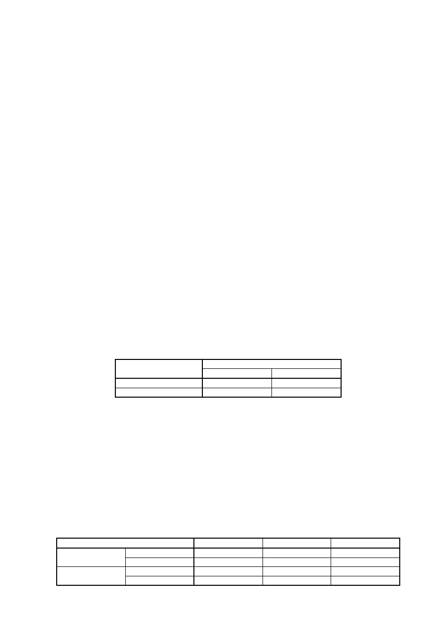
Table 3.1: Recommended values for partial factors for fatigue strength
Consequence of failure
Assessment method
Low consequence
High consequence
Damage tolerant
1,00
1,15
Safe life
1,15
1,35
4 Stresses from fatigue actions
(1)
Modelling for nominal stresses should take into account all action effects including distortional effects
and should be based on a linear elastic analysis for members and connections
(2)
For latticed girders made of hollow sections the modelling may be based on a simplified truss model
with pinned connections. Provided that the stresses due to external loading applied to members between
joints are taken into account the effects from secondary moments due to the stiffness of the connection can
be allowed for by the use of k
1
-factors
(see Table 4.1 for circular hollow sections, Table 4.2 for
rectangular
Table 4.1: k
1
-factors for circular hollow sections under in-plane loading
Type of joint
Chords
Verticals
Diagonals
K ty
pe 1,5
-
1,3
Gap joints
N type / KT type
1,5
1,8
1,4
K ty
pe 1,5
1,
2
Overlap joints
N type / KT type
1,5
1,65
1,25
least equal to those required for ultimate limit state verifications
hollow sections; these sections are subject to the geometrical restrictions according to Table 8.7).
BS EN 1993-1-9 : 2005
-
Š
‹
Š
‹
Š
‹
-
at the end of the design service life
Licensed copy: BSI USER 06 Document Controller, Midmac Contracting Co. W.L.L, Version correct as of 05/06/2011 14:51, (c) BSI
EN 1993-1-9 : 2005 (E)
12
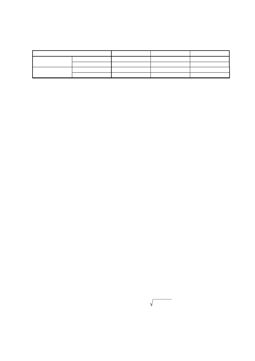
Table 4.2: k
1
-factors for rectangular hollow sections under in-plane loading
Type of joint
Chords
Verticals
Diagonals
K ty
pe 1,5
-
1,5
Gap joints
N type / KT type
1,5
2,2
1,6
K type
1,5
1,3
Overlap joints
N type / KT type
1,5
2,0
1,4
NOTE For the definition of joint types see EN 1993-1-8.
5 Calculation
of
stresses
(1)
Stresses should be calculated at the serviceability limit state.
(2)
Class 4 cross sections are assessed for fatigue loads according to EN 1993-1-5.
NOTE 1 For guidance see EN 1993-2 to EN 1993-6.
NOTE 2 The National Annex may give limitations for class 4 sections.
(3)
Nominal stresses should be calculated at the site of potential fatigue initiation. Effects producing stress
concentrations at details other than those included in Table 8.1 to Table 8.10 should be accounted for by
using a stress concentration factor (SCF) according to 6.3 to give a modified nominal stress.
(4)
When using geometrical (hot spot) stress methods for details covered by Table B.1, the stresses should
be calculated as shown in 6.5.
(5)
The relevant stresses for details in the parent material are:
–
nominal direct stresses
V
–
nominal shear stresses
W
NOTE For effects of combined nominal stresses see 8(3).
(6)
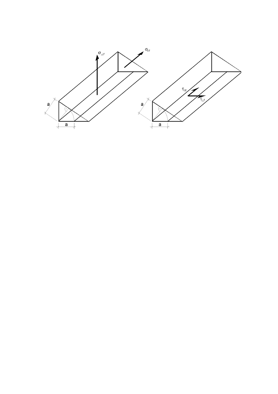
The relevant stresses in the welds are (see Figure 5.1)
–
normal stresses
wf
transverse to the axis of the weld:
2
f
2
f
wf
A
A
W
V
V
–
shear stresses
wf
longitudinal to the axis of the weld:
f
||
wf
W
W
for which two separate checks should be performed.
NOTE The above procedure differs from the procedure given for the verification of fillet welds for
the ultimate limit state, given in EN 1993-1-8.
-
1
NOTE Ranges of geometric validity:
2
For CHS planar joints (K-, N-, KT-joints):
30
60
For SHS joints (K-, N-, KT-joints):
BS EN 1993-1-9 : 2005
Š
‹
Š
‹
0, 30
0,60
12,0
30, 0
0, 25
1,00
30
60
β
γ
τ
θ
≤ ≤
≤ ≤
≤ ≤
° ≤ ≤ °
0, 40
0, 60
6, 25
12,5
0, 25
1,00
30
60
β
γ
τ
θ
≤ ≤
≤ ≤
≤ ≤
° ≤ ≤ °
Licensed copy: BSI USER 06 Document Controller, Midmac Contracting Co. W.L.L, Version correct as of 05/06/2011 14:51, (c) BSI
EN 1993-1-9 : 2005 (E)
13
relevant stresses
V
f
relevant
stresses
W
f
Figure 5.1: Relevant stresses in the fillet welds
6 Calculation of stress ranges
6.1 General
(1)
The fatigue assessment should be carried out using
–
nominal stress ranges for details shown in Table 8.1 to Table 8.10,
–
modified nominal stress ranges where, e.g. abrupt changes of section occur close to the initiation site
which are not included in Table 8.1 to Table 8.10 or
–
geometric stress ranges where high stress gradients occur close to a weld toe in joints covered by
Table B.1
NOTE The National Annex may give information on the use of the nominal stress ranges, modified
nominal stress ranges or the geometric stress ranges. For detail categories for geometric stress ranges
see Annex B.
(2)
The design value of stress range to be used for the fatigue assessment should be the stress ranges
J
Ff
E,2
corresponding to N
C
= 2
u10
6
cycles.
6.2 Design value of nominal stress range
(1)
The design value of nominal stress ranges
J
Ff
E,2
and
J
Ff
W
E,2
should be determined as follows:
J
Ff
E,2
=
1
u
2
u
i
u ... u
n
u (J
Ff
Q
k
)
(6.1)
J
Ff
W
E,2
=
1
u
2
u
i
u ... u
n
u W(J
Ff
Q
k
)
where (
J
Ff
Q
k
),
W(J
Ff
Q
k
) is the stress range caused by the fatigue loads specified in EN 1991
i
are damage equivalent factors depending on the spectra as specified in the relevant parts of EN
1993.
(2)
Where no appropriate data for
i
are available the design value of nominal stress range may be
determined using the principles in Annex A.
NOTE The National Annex may give informations supplementing Annex A.
BS EN 1993-1-9 : 2005
Licensed copy: BSI USER 06 Document Controller, Midmac Contracting Co. W.L.L, Version correct as of 05/06/2011 14:51, (c) BSI

EN 1993-1-9 : 2005 (E)
14
6.3 Design value of modified nominal stress range
(1)
The design value of modified nominal stress ranges
J
Ff
E,2
and
J
Ff
W
E,2
should be determined as
follows:
J
Ff
E,2
= k
f
u
1
u
2
u
i
u ... u
n
u (J
Ff
Q
k
)
(6.2)
J
Ff
W
E,2
= k
f
u
1
u
2
u
i
u ... u
n
u W(J
Ff
Q
k
)
where k
f
is the stress concentration factor to take account of the local stress magnification in relation to
detail geometry not included in the reference
'V
R
-N-curve
NOTE k
f
-values may be taken from handbooks or from appropriate finite element calculations.
6.4 Design value of stress range for welded joints of hollow sections
(1)
Unless more accurate calculations are carried out the design value of modified nominal stress range
J
Ff
E,2
should be determined as follows using the simplified model in 4(2):
*
2
,
E
Ff
1
2
,
E
Ff
k
V
'
J
V
'
J
(6.3)
where
*
2
,
E
Ff
V
'
J
is the design value of stress range calculated with a simplified truss model with pinned
joints
k
1
is the magnification factor according to Table 4.1 and Table 4.2.
6.5 Design value of stress range for geometrical (hot spot) stress
(1)
The design value of geometrical (hot spot) stress range
J
Ff
E,2
should be determined as follows:
*
2
,
E
Ff
f
2
,
E
Ff
k
V
'
J
V
'
J
(6.4)
where k
f
is the stress concentration factor
7 Fatigue
strength
7.1 General
(1)
The fatigue strength for nominal stress ranges is represented by a series of (log
R
) – (log N) curves
and (log
W
R
) – (log N) curves (S-N-curves), which correspond to typical detail categories. Each detail
category is designated by a number which represents, in N/mm
2
, the reference value
C
and
W
C
for the
fatigue strength at 2 million cycles.
(2)
For constant amplitude nominal stress ranges the fatigue strength can be obtained as follows:
6
6
m
C
R
m
R
10
5
N
for
3
m
with
10
2
N
u
d
u
V
'
V
'
, see
Figure 7.1
8
6
m
C
R
m
R
10
N
for
5
m
with
10
2
N
d
u
W
'
W
'
, see Figure 7.2
C
C
3
/
1
D
737
,
0
5
2
V
'
V
'
¸
¹
·
¨
©
§
V
'
is the constant amplitude fatigue limit, see
Figure 7.1, and
BS EN 1993-1-9 : 2005
Š
‹
Licensed copy: BSI USER 06 Document Controller, Midmac Contracting Co. W.L.L, Version correct as of 05/06/2011 14:51, (c) BSI
EN 1993-1-9 : 2005 (E)
15
C
C
5
/
1
L
457
,
0
100
2
W
'
W
'
¸
¹
·
¨
©
§
W
'
is the cut off limit, see Figure 7.2.
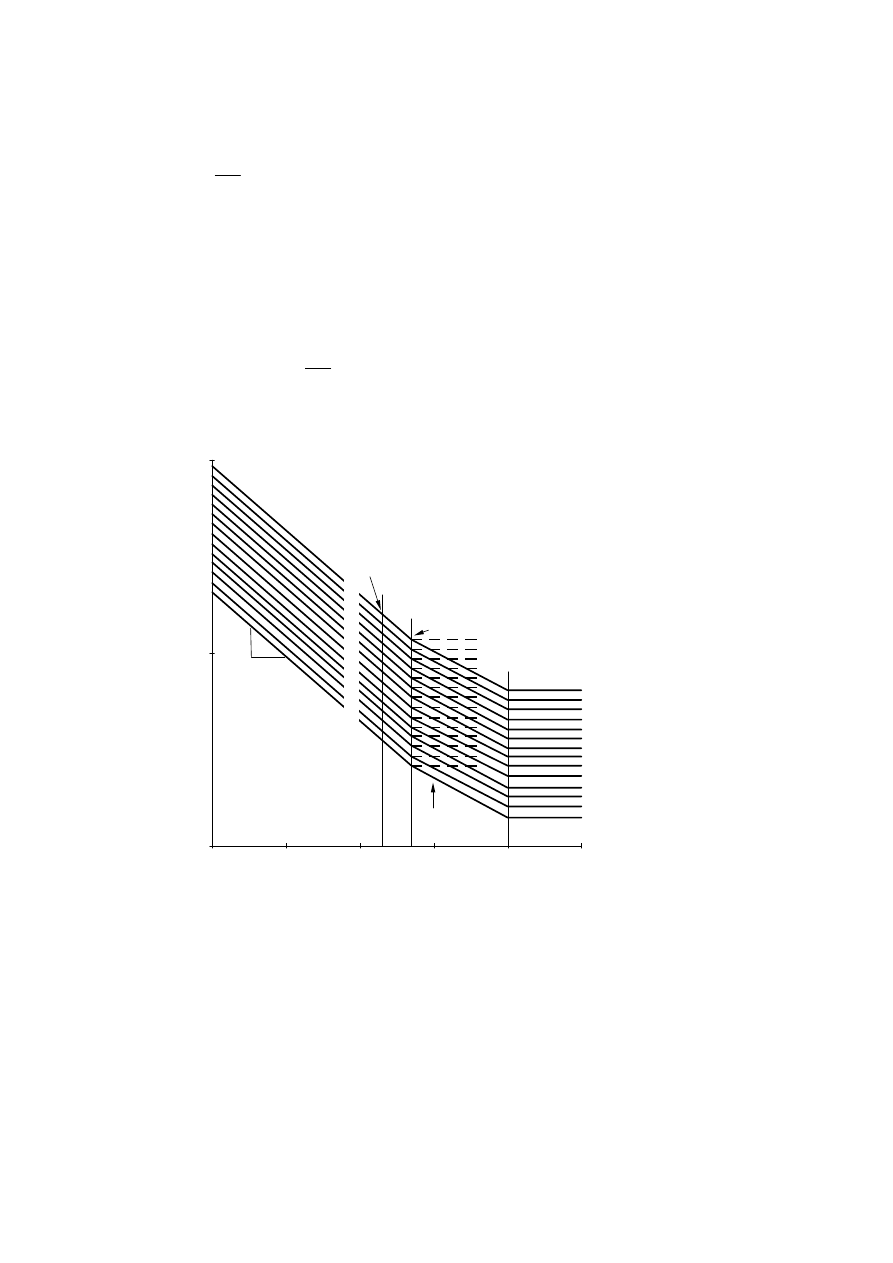
(3)
For nominal stress spectra with stress ranges above and below the constant amplitude fatigue limit
D
the fatigue strength should be based on the extended fatigue strength curves as follows:
8
6
6
m
D
R
m
R
6
6
m
C
R
m
R
10
N
10
5
for
5
m
with
10
5
N
10
5
N
for
3
m
with
10
2
N
d
d
u
u
V
'
V
'
u
d
u
V
'
V
'
D
D
5
/
1
L
549
,
0
100
5
V
'
V
'
¸
¹
·
¨
©
§
V
'
is the cut off limit, see
Figure 7.1.
Direct stress r
ange
'V
R
[N/
mm²]
10
100
1000
1,0E+04
1,0E+05
1,0E+06
1,0E+07
1,0E+08
1,0E+09
3
m = 3
1
m = 5
140
125
112
1
36
40
45
50
56
63
71
80
90
100
160
2
2
5
1 Detail category
'V
C
2 Constant amplitude
fatigue limit
'V
D
3 Cut-off limit
'V
L
Endurance, number of cycles N
Figure 7.1: Fatigue strength curves for direct stress ranges
BS EN 1993-1-9 : 2005
Licensed copy: BSI USER 06 Document Controller, Midmac Contracting Co. W.L.L, Version correct as of 05/06/2011 14:51, (c) BSI
EN 1993-1-9 : 2005 (E)
16
Sh
ear
str
ess
rang
e
'W
R
[N/
m
m²]
10
100
1000
1,0E+04
1,0E+05
1,0E+06
1,0E+07
1,0E+08
1,0E+09
2
m = 5
1
100
80
1
2
1 Detail category
'W
C
2 Cut-off limit
'W
L
Endurance, number of cycles N
Figure 7.2: Fatigue strength curves for shear stress ranges
NOTE 1 When test data were used to determine the appropriate detail category for a particular
constructional detail, the value of the stress range
C
corresponding to a value of N
C
= 2 million
cycles were calculated for a 75% confidence level of 95% probability of survival for log N, taking into
account the standard deviation and the sample size and residual stress effects. The number of data
points (not lower than 10) was considered in the statistical analysis, see annex D of EN 1990.
NOTE 2 The National Annex may permit the verification of a fatigue strength category for a
particular application provided that it is evaluated in accordance with NOTE 1.
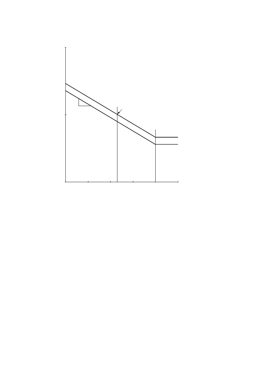
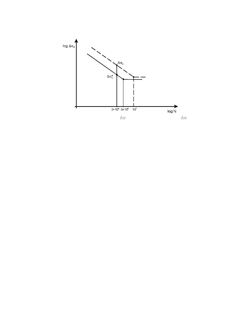
NOTE 3 Test data for some details do not exactly fit the fatigue strength curves
in
Figure 7.1. In order to ensure that non conservative conditions are avoided, such details, marked
with an asterisk, are located one detail category lower than their fatigue strength at 2
u10
6
cycles would
require. An alternative assessment may increase the classification of such details by one detail
category provided that the constant amplitude fatigue limit
'V
D
is defined as the fatigue strength at 10
7
cycles for m=3 (see Figure 7.3).
BS EN 1993-1-9 : 2005
Licensed copy: BSI USER 06 Document Controller, Midmac Contracting Co. W.L.L, Version correct as of 05/06/2011 14:51, (c) BSI
EN 1993-1-9 : 2005 (E)
17
Figure 7.3: Alternative strength
'V
C
for details classified as
'V
C
*
(4) Detail
categories
C
and
C
for nominal stresses are given in
Table 8.1 for plain members and mechanically fastened joints
Table 8.2 for welded built-up sections
Table 8.3 for transverse butt welds
Table 8.4 for weld attachments and stiffeners
Table 8.5 for load carrying welded joints
Table 8.6 for hollow sections
Table 8.7 for lattice girder node joints
Table 8.8 for orthotropic decks – closed stringers
Table 8.9 for orthotropic decks – open stringers
Table 8.10 for top flange to web junctions of runway beams
(5)
The fatigue strength categories
C
for geometric stress ranges are given in Annex B.
NOTE The National Annex may give fatigue strength categories
'V
C
and
'W
C
for details not covered
by Table 8.1 to Table 8.10 and by Annex B.
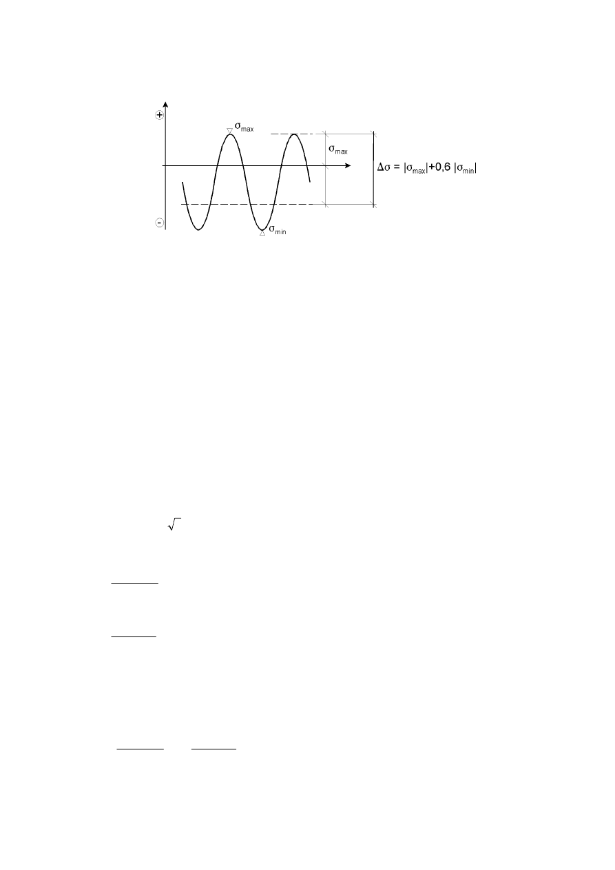
7.2 Fatigue strength modifications
7.2.1 Non-welded or stress-relieved welded details in compression
(1)
In non-welded details or stress-relieved welded details, the mean stress influence on the fatigue
strength may be taken into account by determining a reduced effective stress range
E,2
in the fatigue
assessment when part or all of the stress cycle is compressive.
(2)
The effective stress range may be calculated by adding the tensile portion of the stress range and 60%
of the magnitude of the compressive portion of the stress range, see Figure 7.4.
BS EN 1993-1-9 : 2005
Licensed copy: BSI USER 06 Document Controller, Midmac Contracting Co. W.L.L, Version correct as of 05/06/2011 14:51, (c) BSI
EN 1993-1-9 : 2005 (E)
18
+ tension
– compression
Figure 7.4: Modified stress range for non-welded or stress relieved details
7.2.2 Size
effect
(1)
The size effect due to thickness or other dimensional effects should be taken into account as given in
Table 8.1 to Table 8.10. The fatigue strength then is given by:
C
s
red
,
C
k
V
'
V
'
(7.1)
8 Fatigue
verification
(1)
Nominal, modified nominal or geometric stress ranges due to frequent loads
\
1
Q
k
(see EN 1990)
should not exceed
ranges
stress
shear
for
3
/
f
5
,
1
ranges
stress
direct
for
f
5
,
1
y
y
d
W
'
d
V
'
(8.1)
(2)
It should be verified that under fatigue loading
0
,
1
/
Mf
C
2
,
E
Ff
d
J
V
'
V
'
J
and
(8.2)
0
,
1
/
Mf
C
2
,
E
Ff
d
J
W
'
W
'
J
NOTE Table 8.1 to Table 8.9 require stress ranges to be based on principal stresses for some details.
(3)
Unless otherwise stated in the fatigue strength categories in Table 8.8 and Table 8.9, in the case of
combined stress ranges
'V
E,2
and
'W
E,2
it should be verified that:
0
,
1
/
/
5
Mf
C
2
,
E
Ff
3
Mf
C
2
,
E
Ff
d
¸¸¹
·
¨¨©
§
J
W
'
W
'
J
¸¸¹
·
¨¨©
§
J
V
'
V
'
J
(8.3)
(4)
When no data for
E,2
or
E,2
are available the verification format in Annex A may be used.
BS EN 1993-1-9 : 2005
Licensed copy: BSI USER 06 Document Controller, Midmac Contracting Co. W.L.L, Version correct as of 05/06/2011 14:51, (c) BSI

EN 1993-1-9 : 2005 (E)
19
NOTE 1 Annex A is presented for stress ranges in longitudinal direction. This presentation may be
adopted also for shear stress ranges.
NOTE 2 The National Annex may give information on the use of Annex A.
BS EN 1993-1-9 : 2005
Š
‹
Licensed copy: BSI USER 06 Document Controller, Midmac Contracting Co. W.L.L, Version correct as of 05/06/2011 14:51, (c) BSI
EN 1993-1-9 : 2005 (E)
20
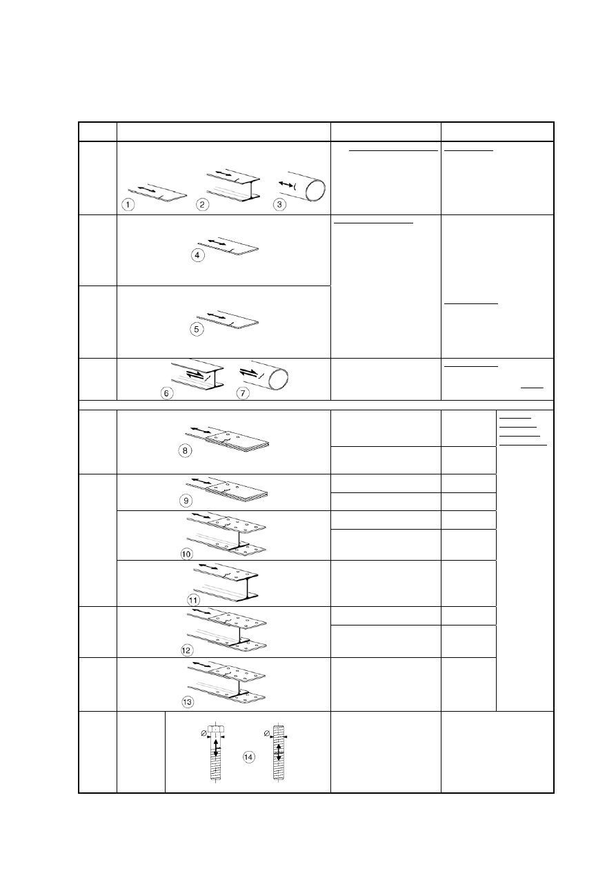
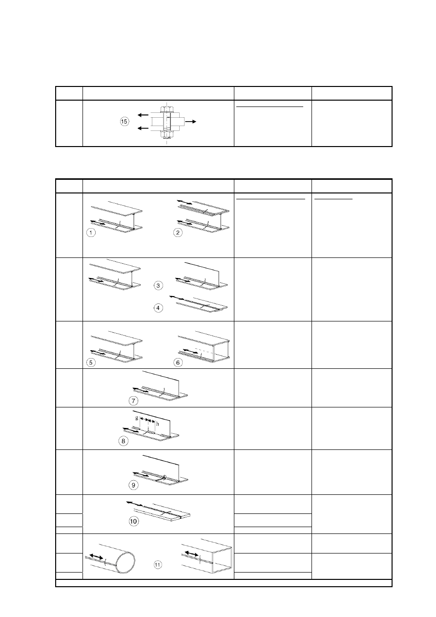
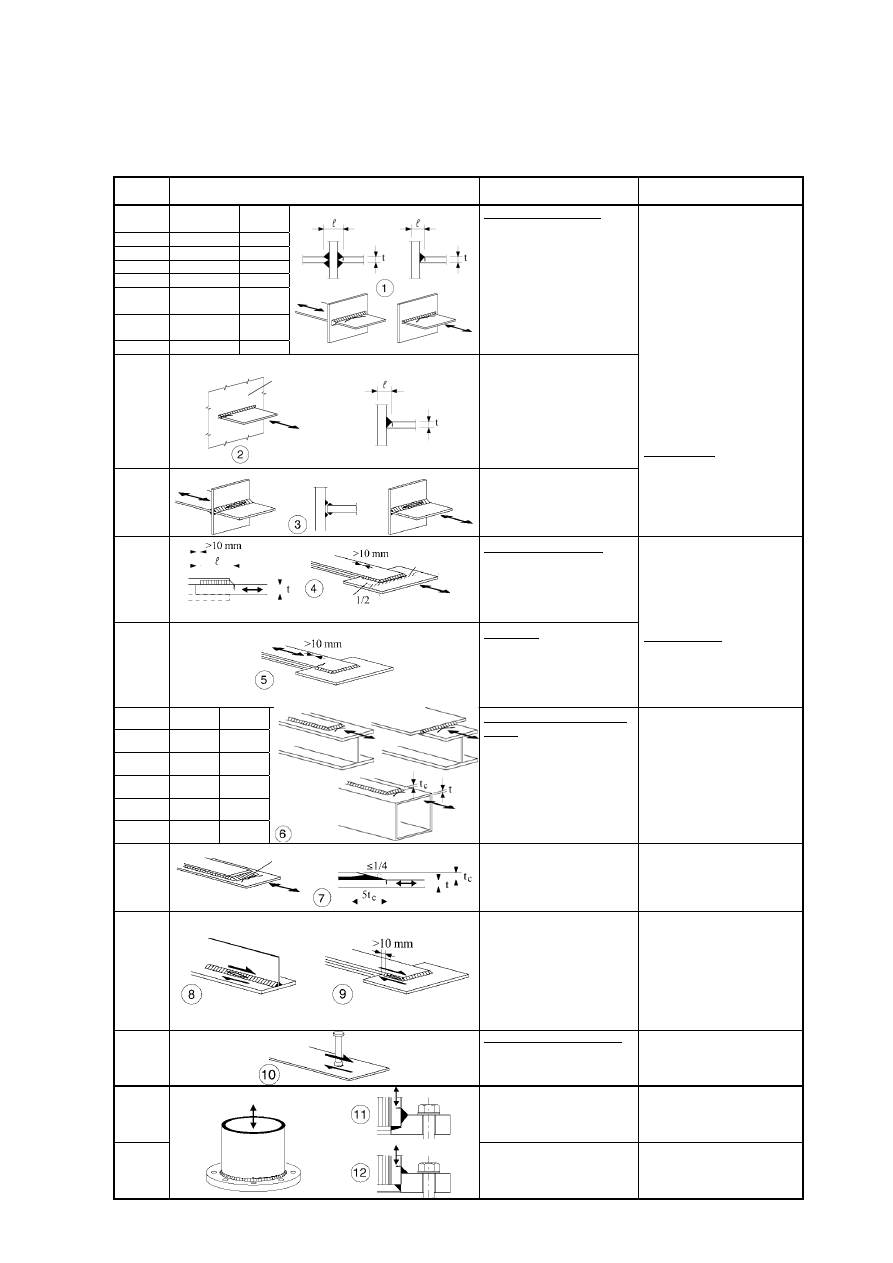
Table 8.1: Plain members and mechanically fastened joints
Detail
category
Constructional detail
Description
Requirements
160
NOTE The fatigue strength curve associated with category 160
is the highest. No detail can reach a better fatigue strength at any
number of cycles.
Rolled or extruded products:
1) Plates and flats with as rolled
2) Rolled sections with as rolled
3) Seamless hollow sections,
either rectangular or circular.
Details 1) to 3):
Sharp edges, surface and rolling
flaws to be improved by grinding
until removed and smooth
transition achieved.
140
125
Sheared or gas cut plates:
4) Machine gas cut or sheared
material with subsequent
dressing.
5) Material with machine gas cut
edges having shallow and
regular drag lines or manual gas
cut material, subsequently
dressed to remove all edge
discontinuities.
Machine gas cut with cut quality
according to EN 1090.
4) All visible signs of edge
discontinuities to be removed.
The cut areas are to be machined
or ground and all burrs to be
removed.
Any machinery scratches for
example from grinding
operations, can only be parallel to
the stresses.
Details 4) and 5):
- Re-entrant corners to be
improved by grinding (slope
¼) or evaluated using the
appropriate stress concentration
factors.
- No repair by weld refill.
100
m = 5
6) and 7)
Rolled or extruded products as
in details 1), 2), 3)
Details 6) and 7):
'W calculated from:
t
I
)
t
(
S
V
W
For detail 1 – 5 made of weathering steel use the next lower category.
8) Double covered symmetrical
joint with preloaded high
strength bolts.
8)
'V to be
calculated on
the gross
cross-section.
112
8) Double covered symmetrical
joint with preloaded injection
bolts.
8) ... gross
cross-section.
9) Double covered joint with
fitted bolts.
9) ... net cross-
section.
9) Double covered joint with
non preloaded injection bolts.
9) ... net cross-
section.
10) One sided connection with
preloaded high strength bolts.
10) ... gross
cross-section.
10) One sided connection with
preloaded injection bolts.
10) ... gross
cross-section.
90
11) Structural element with
holes subject to bending and
axial forces
11) ... net
cross-section.
12) One sided connection with
fitted bolts.
12) ... net
cross-section.
80
12) One sided connection with
non-preloaded injection bolts.
12) ... net
cross-section.
50
13) One sided or double covered
symmetrical connection with
non-preloaded bolts in normal
clearance holes.
No load reversals.
13) ... net
cross-section.
For bolted
connections
(Details 8) to
13)) in general:
End distance:
e
1
1,5 d
Edge distance:
e
2
1,5 d
Spacing:
p
1
2,5 d
Spacing:
p
2
2,5 d
Detailing to
EN 1993-1-8,
Figure 3.1
50
size effect
for
L > 30mm:
k
s
=(30/
L)
0,25
14) Bolts and rods with rolled or
cut threads in tension.
For large diameters (anchor
bolts) the size effect has to be
taken into account with k
s
.
14)
'V to be calculated using the
tensile stress area of the bolt.
Bending and tension resulting
from prying effects and bending
stresses from other sources must
be taken into account.
For preloaded bolts, the reduction
of the stress range may be taken
into account.
edges;
edges;
BS EN 1993-1-9 : 2005
Š
‹
Š
‹
Licensed copy: BSI USER 06 Document Controller, Midmac Contracting Co. W.L.L, Version correct as of 05/06/2011 14:51, (c) BSI
EN 1993-1-9 : 2005 (E)
21
Table 8.1 (continued): Plain members and mechanically fastened joints
Detail
category
Constructional detail
Description
Requirements
100
m=5
Bolts in single or double shear
Thread not in the shear plane
15)
- Fitted bolts
- normal bolts without load
reversal (bolts of grade 5.6, 8.8
or 10.9)
15)
'W calculated on the shank area of
the bolt.
Table 8.2: Welded built-up sections
Detail
category
Constructional detail
Description
Requirements
125
Continuous longitudinal welds:
1) Automatic or fully mechanized
butt welds carried
out from both
2) Automatic or fully mechanized
fillet welds. Cover plate ends to
be checked using detail 6) or 7)
in Table 8.5.
Details 1) and 2):
No stop/start position is permitted
except when the repair is
performed by a specialist and
inspection is carried out to verify
the proper execution of the repair.
112
3) Automatic or fully mechanized
fillet or butt weld carried out
from both sides but containing
stop/start positions.
4) Automatic or fully mechanized
butt welds made from one side
only, with a continuous backing
bar, but without start/stop
positions.
4) When this detail contains
stop/start positions category 100
to be used.
100
5) Manual fillet or butt weld.
6) Manual or automatic
or fully
mechanized butt welds carried
out from one side only,
particularly for box girders
5), 6) A very good fit between the
flange and web plates is essential.
The web edge to be prepared such
that the root face is adequate for
the achievement of regular root
penetration without break-out.
100
7) Repaired automatic
or fully
mechanized or manual fillet
or butt welds for categories
1) to 6).
7) Improvement by grinding
performed by specialist to remove
all visible signs and adequate
verification can restore the
original category.
80
g/h 2,5
8) Intermittent longitudinal fillet
welds.
8) based on direct stress in
flange.
71
9) Longitudinal butt weld, fillet
weld or intermittent weld with a
cope hole height not greater than
60 mm.
For cope holes with a height
> 60 mm see detail 1) in Table
8.4
9) based on direct stress in
flange.
125
10) Longitudinal butt weld, both
sides ground flush parallel to
load direction, 100% NDT
112
10) No grinding and no
start/stop
90
10) with start/stop positions
sides.
140
11) Automatic or fully mechanized 11) Wall thickness t
d 12,5 mm.
125
90
11) with stop/start positions
11) Wall thickness t > 12,5 mm.
For details 1 to 11 made with fully mechanized welding the categories for automatic welding apply.
start positions in hollow sections
longitudinal seam weld without stop/
11) Automatic or fully mechanized
start positions in hollow sections
longitudinal seam weld without stop/
BS EN 1993-1-9 : 2005
Š
‹
Licensed copy: BSI USER 06 Document Controller, Midmac Contracting Co. W.L.L, Version correct as of 05/06/2011 14:51, (c) BSI
EN 1993-1-9 : 2005 (E)
22
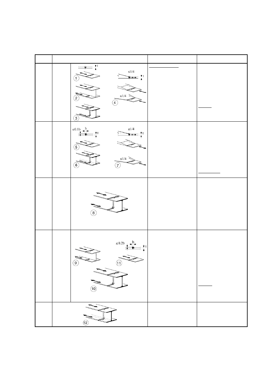
Table 8.3: Transverse butt welds
Detail
category
Constructional detail
Description
Requirements
112
size effect
for
t>25mm:
k
s
=(25/t)
0,2
Without backing bar:
1) Transverse splices in plates
and flats.
2) Flange and web splices in
plate girders before assembly.
3) Full cross-section butt welds
of rolled sections without cope
holes.
4) Transverse splices in plates or
flats tapered in width or in
thickness, with a slope ¼.
- All welds ground flush to plate
surface parallel to direction of
the arrow.
- Weld run-on and run-off pieces
to be used and subsequently
removed, plate edges to be
ground flush in direction of
stress.
- Welded from both sides;
checked by NDT.
Detail 3):
Applies only to joints of rolled
sections, cut and welded.
90
size effect
for
t>25mm:
k
s
=(25/t)
0,2
5) Transverse splices in plates or
flats.
6) Full cross-section butt welds
of rolled sections without cope
holes.
7) Transverse splices in plates or
flats tapered in width or in
thickness with a slope ¼.
Translation of welds to be
machined notch free.
- The height of the weld convexity
to be not greater than 10% of the
weld width, with smooth
transition to the plate surface.
- Weld run-on and run-off pieces
to be used and subsequently
removed, plate edges to be
ground flush in direction of
stress.
- Welded from both sides;
checked by NDT.
Details 5 and 7:
Welds made in flat position.
90
size effect
for
t>25mm:
k
s
=(25/t)
0,2
8) As detail 3) but with cope
holes.
- All welds ground flush to plate
surface parallel to direction of
the arrow.
- Weld run-on and run-off pieces
to be used and subsequently
removed, plate edges to be
ground flush in direction of
stress.
- Welded from both sides;
checked by NDT.
- Rolled sections with the same
dimensions without tolerance
differences
80
size effect
for
t>25mm:
k
s
=(25/t)
0,2
9) Transverse splices in welded
plate girders without cope hole.
10) Full cross-section butt welds
of rolled sections with cope
holes.
11) Transverse splices in plates,
flats, rolled sections or plate
girders.
- The height of the weld convexity
to be not greater than 20% of the
weld width, with smooth
transition to the plate surface.
- Weld not ground flush
- Weld run-on and run-off pieces
to be used and subsequently
removed, plate edges to be
ground flush in direction of
stress.
- Welded from both sides;
checked by NDT.
Detail 10:
The height of the weld convexity
to be not greater than 10% of the
weld width, with smooth
transition to the plate surface.
63
12) Full cross-section butt welds
of rolled sections without cope
hole.
- Weld run-on and run-off pieces
to be used and subsequently
removed, plate edges to be
ground flush in direction of
stress.
- Welded from both sides.
BS EN 1993-1-9 : 2005
Š
‹
Licensed copy: BSI USER 06 Document Controller, Midmac Contracting Co. W.L.L, Version correct as of 05/06/2011 14:51, (c) BSI
EN 1993-1-9 : 2005 (E)
23
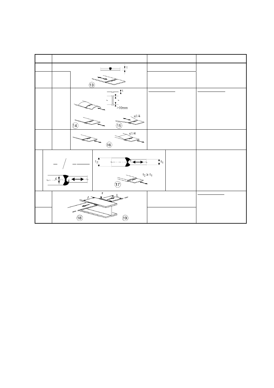
Table 8.3 (continued): Transverse butt welds
Detail
category
Constructional detail
Description
Requirements
36
13) Butt welds made from one
side only.
71
size effect
for
t>25mm:
k
s
=(25/t)
0,2
13) Butt welds made from one
side only when full penetration
checked by appropriate NDT.
13) Without backing strip.
71
size effect
for
t>25mm:
k
s
=(25/t)
0,2
With backing strip:
14) Transverse splice.
15) Transverse butt weld
tapered in width or thickness
with a slope ¼.
Also valid for curved plates.
Details 14) and 15):
Fillet welds attaching the backing
strip to terminate 10 mm from
the edges of the stressed plate.
Tack welds inside the shape of
butt welds.
50
size effect
for
t>25mm:
k
s
=(25/t)
0,2
16) Transverse butt weld on a
permanent backing strip tapered
in width or thickness with a
slope ¼.
Also valid for curved plates.
16) Where backing strip fillet
welds end < 10 mm from the
plate edge, or if a good fit cannot
be guaranteed.
71
size effect for t>25mm and/or
generalization for eccentricity:
¸¸¹
·
¨¨©
§
¸¸¹
·
¨¨©
§
5
,
1
2
5
,
1
1
5
,
1
1
1
2
,
0
1
s
t
t
t
t
e
6
1
t
25
k
t
2
t t
1
slope
d 1/2
17) Transverse butt
weld, different
thicknesses without
transition,
centrelines aligned.
18) Transverse butt weld at
intersecting flanges.
As
detail 4
in
Table 8.4
19) With transition radius
according to Table 8.4, detail 4
Details 18) and 19)
The fatigue strength of the
continuous component has to be
checked with Table 8.4, detail 4
or detail 5.
40
BS EN 1993-1-9 : 2005
Š
‹
Licensed copy: BSI USER 06 Document Controller, Midmac Contracting Co. W.L.L, Version correct as of 05/06/2011 14:51, (c) BSI
EN 1993-1-9 : 2005 (E)
24
Table 8.4: Weld attachments and stiffeners
Detail
category
Constructional detail
Description
Requirements
80 L50mm
71 50<L80mm
63 80<L100mm
56 L>100mm
Longitudinal attachments:
1) The detail category varies
according to the length of the
attachment L.
The thickness of the attachment
must be less than its height. If not
see Table 8.5, details 5 or 6.
71
L>100mm
<45°
2) Longitudinal attachments to
plate or tube.
80 r>150mm
reinforced
3) Longitudinal fillet welded
gusset with radius transition to
plate or tube; end of fillet weld
reinforced (full penetration);
length of reinforced weld > r.
90
3
1
r t
or
r>150mm
71
3
1
r
6
1
d
d
50
6
1
r
4) Gusset plate, welded to the
edge of a plate or beam flange.
Details 3) and 4):
Smooth transition radius r formed
by initially machining or gas
cutting the gusset plate before
welding, then subsequently
grinding the weld area parallel to
the direction of the arrow so that
the transverse weld toe is fully
removed.
40
5) As welded, no radius
transition.
80 50mm
71 50<80mm
Transverse attachments:
6) Welded to plate.
7) Vertical stiffeners welded to a
beam or plate girder.
8) Diaphragm of box girders
welded to the flange or the web.
May not be possible for small
hollow sections.
The values are also valid for ring
stiffeners.
Details 6) and 7):
Ends of welds to be carefully
ground to remove any undercut
that may be present.
7)
'V to be calculated using
principal stresses if the stiffener
terminates in the web, see left
side.
80
9) The effect of welded shear
studs on base material.
l
l
l
BS EN 1993-1-9 : 2005
Š
‹
Licensed copy: BSI USER 06 Document Controller, Midmac Contracting Co. W.L.L, Version correct as of 05/06/2011 14:51, (c) BSI
EN 1993-1-9 : 2005 (E)
25
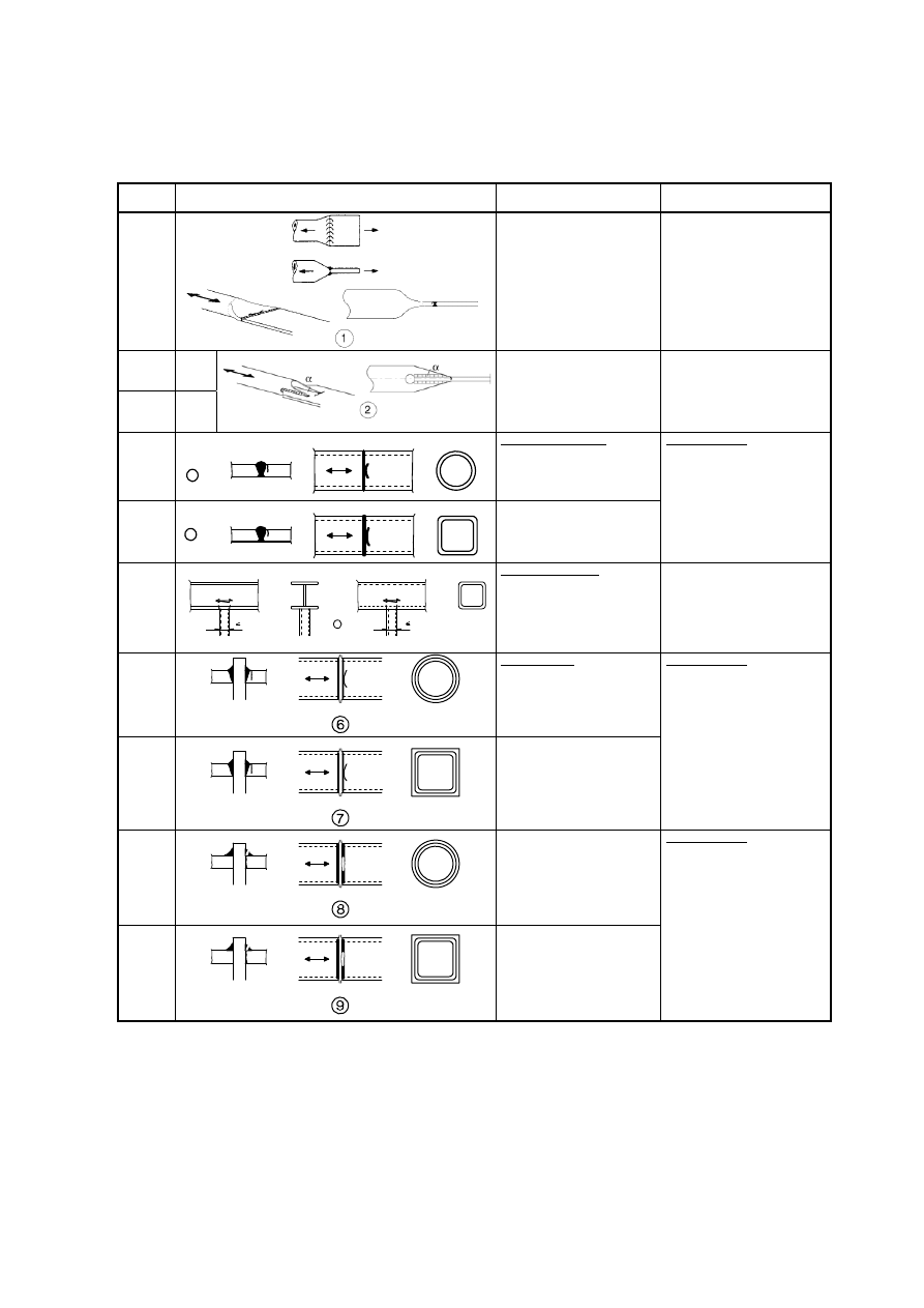
Table 8.5: Load carrying welded joints
Detail
category
Constructional detail
Description
Requirements
80 <50
mm
all t
[mm]
71 50<80
all
t
63 80<100
all
t
56 100<120
all
t
56 >120
t20
50
120<200
>200
t>20
20<t30
45
200<300
>300
t>30
30<t50
40 >300
t>50
Cruciform and Tee joints:
1) Toe failure in full penetration
butt welds and all partial
penetration joints.
As
detail 1
in
Table 8.5
2) Toe failure from edge of
attachment to plate, with stress
peaks at weld ends due to local
plate deformations.
36*
3) Root failure in partial penetration
Tee-butt joints or fillet welded
joint and in Tee-butt weld,
according
to
1) Inspected and found free from
discontinuities and misalignments
outside the tolerances of
EN 1090.
2) For computing
'V, use
modified nominal stress.
3) In partial penetration joints two
fatigue assessments are required.
Firstly, root cracking evaluated
according to stresses defined in
section 5, using category 36* for
'
w
and category 80 for
'
w
.
Secondly, toe cracking is
evaluated by determining
'V in
the load-carrying plate.
Details 1) to 3):
The misalignment of the load-
carrying plates should not exceed
15 % of the thickness of the
intermediate plate.
As
detail 1
in
Table 8.5
stressed area of main panel: slope = 1/2
Overlapped welded joints:
4) Fillet welded lap joint.
45*
Overlapped:
5) Fillet welded lap joint.
4)
'V in the main plate to be
calculated on the basis of area
shown in the sketch.
5)
'V to be calculated in the
overlapping plates.
Details 4) and 5):
- Weld terminations more than 10
mm from plate edge.
- Shear cracking in the weld
should be checked using detail
8).
t
c
<t t
c
t
56* t20 -
50 20<t30
t20
45 30<t50
20<t30
40 t>50
30<t50
36 -
t>50
Cover plates in beams and plate
girders:
6) End zones of single or
multiple welded cover plates,
with or without transverse end
weld.
6) If the cover plate is wider than
the flange, a transverse end weld
is needed. This weld should be
carefully ground to remove
undercut.
The minimum length of the cover
plate is 300 mm. For shorter
attachments size effect see detail
1).
56
reinforced transverse end weld
7) Cover plates in beams and
plate girders.
5t
c
is the minimum length of the
reinforcement weld.
7) Transverse end weld ground
flush. In addition, if t
c
>20mm,
front of plate at the end ground
with a slope < 1 in 4.
80
m=5
8) Continuous fillet welds
transmitting a shear flow, such
as web to flange welds in plate
girders.
9) Fillet welded lap joint.
8)
'W to be calculated from the
weld throat area.
9)
'W to be calculated from the
weld throat area considering the
total length of the weld. Weld
terminations more than 10 mm
from the plate edge, see also 4)
and 5) above.
see EN
1994-2
(90
m=8)
Welded stud shear connectors:
10) For composite application
10)
'W to be calculated from the
nominal cross section of the stud.
71
11) Tube socket joint with 80%
full penetration butt welds.
11) Weld toe ground.
'V
computed in tube.
40
12) Tube socket joint with fillet
welds.
12)
'V computed in tube.
Figure
4.6
in
EN 1993-1-8:2005.
BS EN 1993-1-9 : 2005
Š
‹
flexible panel
Licensed copy: BSI USER 06 Document Controller, Midmac Contracting Co. W.L.L, Version correct as of 05/06/2011 14:51, (c) BSI
EN 1993-1-9 : 2005 (E)
26
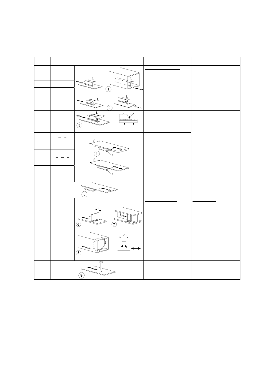
Table 8.6: Hollow sections (t 12,5 mm)
Detail
category
Constructional detail
Description
Requirements
71
1) Tube-plate joint, tubes flatted,
butt weld (X-groove)
1)
'V computed in tube.
Only valid for tube diameter less
than 200 mm.
71 45°
63 >45°
2) Tube-plate joint, tube slitted
and welded to plate. Holes at
end of slit.
2)
'V computed in tube.
Shear cracking in the weld should
be verified using Table 8.5, detail
8).
71
3
Transverse butt welds:
3) Butt-welded end-to-end
connections between circular
structural hollow sections.
56
4
4) Butt-welded end-to-end
connections between rectangular
structural hollow sections.
Details 3) and 4):
- Weld convexity 10% of weld
width, with smooth transitions.
- Welded in flat position,
inspected and found free from
defects outside the tolerances
EN 1090.
- Classify 2 detail categories
higher if t > 8 mm.
71
5
1 00 mm
10 0 m m
5
5
Welded attachments:
5) Circular or rectangular
structural hollow section, fillet-
welded to another section.
5)
- Non load-carrying welds.
- Width parallel to stress direction
100 mm.
- Other cases see Table 8.4.
50
Welded splices:
6) Circular structural hollow
sections, butt-welded end-to-end
with an intermediate plate.
45
7) Rectangular structural hollow
sections, butt welded end-to-end
with an intermediate plate.
Details 6) and 7):
- Load-carrying welds.
- Welds inspected and found free
from defects outside the
tolerances of EN 1090.
- Classify 1 detail category higher
if t > 8 mm.
40
8) Circular structural hollow
sections, fillet-welded end-to-
end with an intermediate plate.
36
9) Rectangular structural hollow
sections, fillet-welded end-to-
end with an intermediate plate.
Details 8) and 9):
- Load-carrying welds.
- Wall thickness t 8 mm.
BS EN 1993-1-9 : 2005
Licensed copy: BSI USER 06 Document Controller, Midmac Contracting Co. W.L.L, Version correct as of 05/06/2011 14:51, (c) BSI
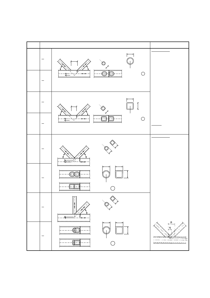
EN 1993-1-9 : 2005 (E)
27
Table 8.7: Lattice girder node joints
Detail
category
Constructional detail
Requirements
90
m=5
0
,
2
t
t
i
0
t
45
m=5
0
,
1
t
t
i
0
Gap joints: Detail 1): K and N joints, circular structural hollow sections:
4
4
t
i
d
i
t
0
0
d
1
+e
i/p
g
71
m=5
0
,
2
t
t
i
0
t
36
m=5
0
,
1
t
t
i
0
Gap joints: Detail 2): K and N joints, rectangular structural hollow sections:
4
4
t
i
b
i
t
0
0
b
2
h
0
g
+e
i/p
Details 1) and 2):
- Separate
assessments
needed
for the chords and the braces.
- For intermediate values of the
ratio t
o
/t
i
interpolate linearly
between detail categories.
- Fillet welds permitted for
braces with wall thickness t
8 mm.
- t
0
and t
i
8mm
- 35° 50°
- b
0
/t
0
ut
0
/t
i
25
- d
0
/t
0
ut
0
/t
i
25
- 0,4
b
i
/b
0
1,0
- 0,25
d
i
/d
0
1,0
- b
0
200 mm
- d
0
300 mm
- -
0,5h
0
e
i/p
0,25h
0
- -
0,5d
0
e
i/p
0,25d
0
- e
o/p
0,02b
0
or 0,02d
0
[e
o/p
is out-of-plane eccentricity]
Detail 2):
0,5(b
o
- b
i
) g 1,1(b
o
- b
i
)
and g 2t
o
71
m=5
4
,
1
t
t
i
0
t
56
m=5
0
,
1
t
t
i
0
Overlap joints: Detail 3): K joints, circular or rectangular structural hollow sections:
b
i
t
i
d
i
t
0
0
d
0
b
h
0
3
4
4
-e
i/p
71
m=5
4
,
1
t
t
i
0
t
50
m=5
0
,
1
t
t
i
0
Overlap joints: Detail 4): N joints, circular or rectangular structural hollow sections:
b
i
t
i
d
i
t
0
0
d
0
b
h
0
4
4
-e
i/p
Details 3) and 4):
- 30 % overlap 100 %
- overlap = (q/p) × 100 %
- Separate
assessments
needed
for the chords and the braces.
- For intermediate values of the
ratio t
o
/t
i
interpolate linearly
between detail categories.
- Fillet welds permitted for
braces with wall thickness t
8 mm.
- t
0
and t
i
8mm
- 35° 50°
- b
0
/t
0
ut
0
/t
i
25
- d
0
/t
0
ut
0
/t
i
25
- 0,4
b
i
/b
0
1,0
- 0,25
d
i
/d
0
1,0
- b
0
200 mm
- d
0
300 mm
- -
0,5h
0
e
i/p
0,25h
0
- -
0,5d
0
e
i/p
0,25d
0
- e
o/p
0,02b
0
or 0,02d
0
[e
o/p
is out-of-plane eccentricity]
Definition of p and q:
BS EN 1993-1-9 : 2005
Licensed copy: BSI USER 06 Document Controller, Midmac Contracting Co. W.L.L, Version correct as of 05/06/2011 14:51, (c) BSI
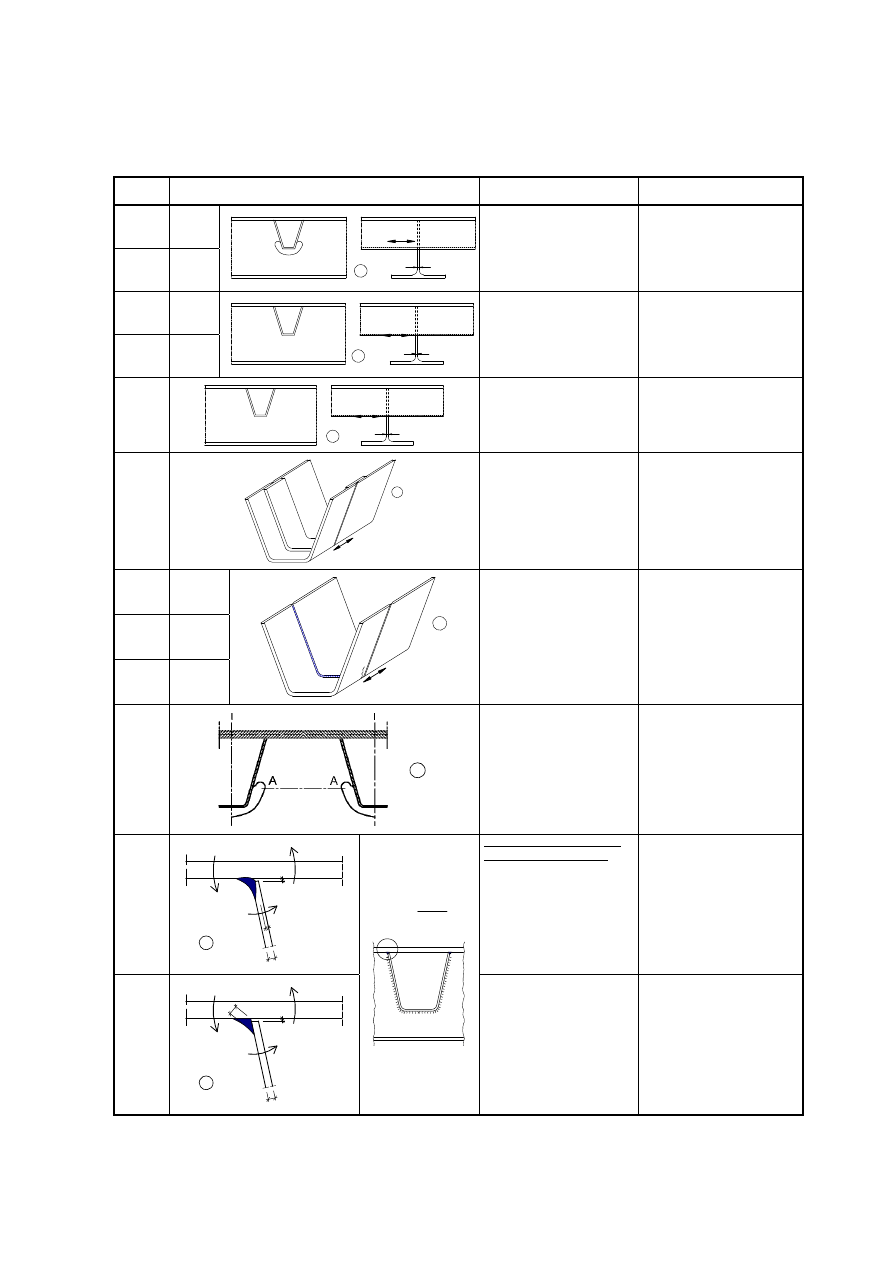
EN 1993-1-9 : 2005 (E)
28
Table 8.8: Orthotropic decks – closed stringers
Detail
category
Constructional detail
Description
Requirements
80 t12mm
71 t>12mm
V
'
1
t
1) Continuous longitudinal
stringer, with additional cutout
in cross girder.
1) Assessment based on the direct
stress range in the longitudinal
stringer.
80 t12mm
71 t>12mm
V
'
2
t
2) Continuous longitudinal
stringer, no additional cutout in
cross girder.
2) Assessment based on the direct
stress range in the stringer.
36
V
'
3
t
3) Separate longitudinal stringer
each side of the cross girder.
3) Assessment based on the direct
stress range in the stringer.
71
'
V
4
4) Joint in rib, full penetration
butt weld with steel backing
plate.
4) Assessment based on the direct
stress range in the stringer.
112
As detail
1, 2, 4 in
Table 8.3
90
As detail
5, 7 in
Table 8.3
80
As detail
9, 11 in
Table 8.3
'
V
5
5) Full penetration butt weld in
rib, welded from both sides,
without backing plate.
5) Assessment based on the direct
stress range in the stringer.
Tack welds inside the shape of
butt welds.
71
6
6) Critical section in web of
cross girder due to cut outs.
6) Assessment based on stress
range in critical section taking
account of Vierendeel effects.
NOTE In case the stress range is
determined according to
EN 1993-2, 9.4.2.2(3), detail
category 112 may be used.
71
mm
2
d
mm
2
d
t
l
r
w
M
M
M
t
a
t
7
Weld connecting deck plate to
trapezoidal or V-section rib
7) Partial penetration weld with
a
t t
7) Assessment based on direct
stress range from bending in the
plate.
50
t
l
r
w
M
M
M
a
mm
5
.
0
d
8
fillet weld
w
w
W
M
'
V
'
8) Fillet weld or partial
penetration welds out of the
range of detail 7)
8) Assessment based on direct
stress range from bending in the
plate.
BS EN 1993-1-9 : 2005
Licensed copy: BSI USER 06 Document Controller, Midmac Contracting Co. W.L.L, Version correct as of 05/06/2011 14:51, (c) BSI
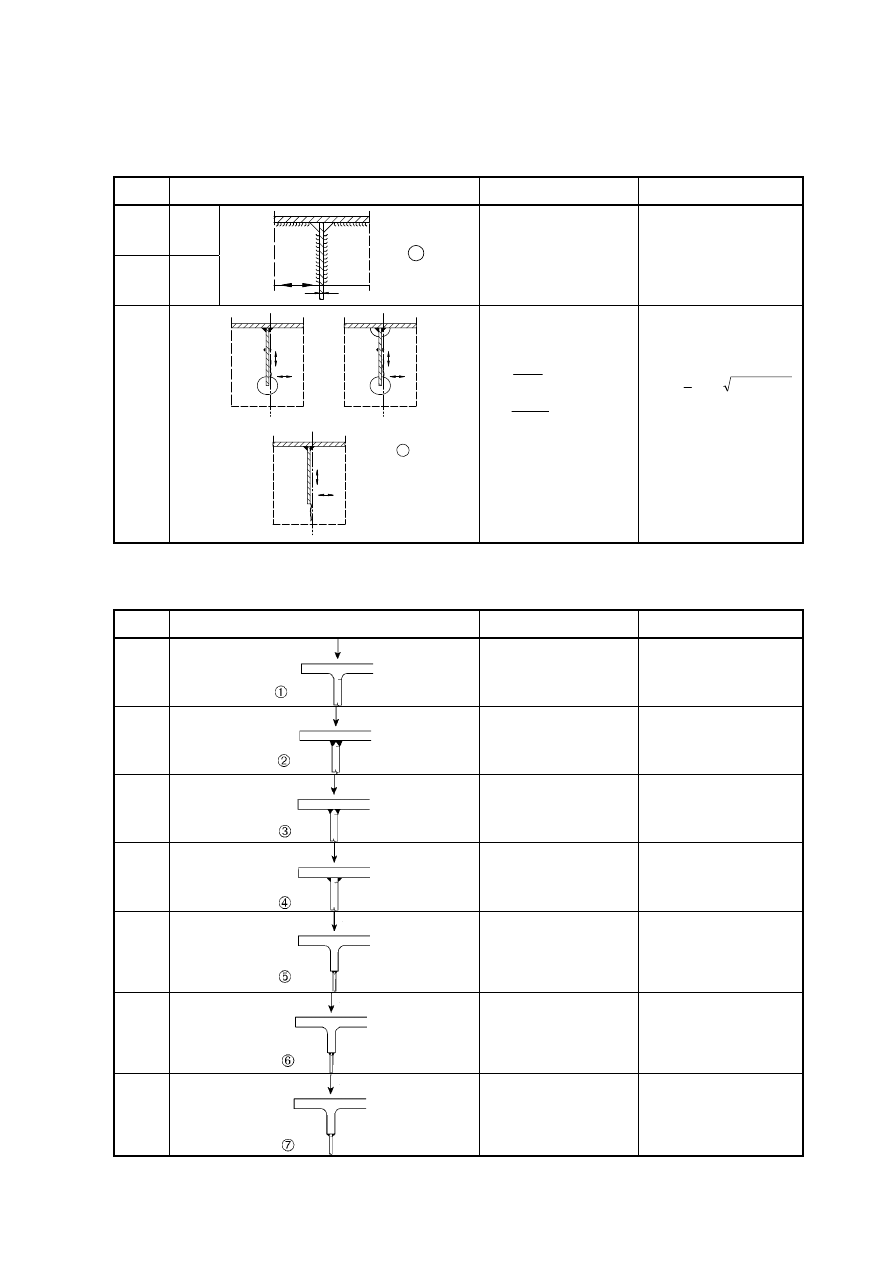
EN 1993-1-9 : 2005 (E)
29
Table 8.9: Orthotropic decks – open stringers
Detail
category
Constructional detail
Description
Requirements
80 t12mm
71 t>12mm
t
'
V
1
1) Connection of longitudinal
stringer to cross girder.
1) Assessment based on the direct
stress range in the stringer.
56
'
'
'
'
'
'
V
V
V
W
W
W
2
s
s
s
s
s
s
2) Connection of continuous
longitudinal stringer to cross
girder.
s
,
net
s
W
M
'
V
'
s
,
net
,
w
s
A
V
'
W
'
Check also stress range between
stringers as defined in EN 1993-
2.
2) Assessment based on
combining the shear stress range
and direct stress range in
the web of the cross girder, as an
equivalent stress range:
2
2
eq
4
2
1
W
'
V
'
V
'
V
'
Table 8.10: Top flange to web junction of runway beams
Detail
category
Constructional detail
Description
Requirements
160
1) Rolled I- or H-sections
1) Vertical compressive stress
range
'V
vert.
in web due to wheel
loads
71
2) Full penetration tee-butt weld
2) Vertical compressive stress
range
'V
vert.
in web due to wheel
loads
36*
3) Partial penetration tee-butt
welds, or effective full
penetration tee-butt weld
conforming with EN 1993-1-8
3) Stress range
'V
vert.
in weld
throat due to vertical compression
from wheel loads
36*
4) Fillet welds
4) Stress range
'V
vert.
in weld
throat due to vertical compression
from wheel loads
71
5) T-section flange with full
penetration tee-butt weld
5) Vertical compressive stress
range
'V
vert.
in web due to wheel
loads
36*
6) T-section flange with partial
penetration tee-butt weld, or
effective full penetration tee-butt
weld conforming with
EN 1993-1-8
6) Stress range
'V
vert.
in weld
throat due to vertical compression
from wheel loads
36*
7) T-section flange with fillet
welds
7) Stress range
'V
vert.
in weld
throat due to vertical compression
from wheel loads
BS EN 1993-1-9 : 2005
Licensed copy: BSI USER 06 Document Controller, Midmac Contracting Co. W.L.L, Version correct as of 05/06/2011 14:51, (c) BSI

EN 1993-1-9 : 2005 (E)
30
Annex A [normative] – Determination of fatigue load parameters and
verification formats
A.1
Determination of loading events
(1)
Typical loading sequences that represent a credible estimated upper bound of all service load events
expected during the fatigue design life should be determined using prior knowledge from similar structures,
see Figure A.1 a).
A.2
Stress history at detail
(1) A stress history should be determined from the loading events at the structural detail under
consideration taking account of the type and shape of the relevant influence lines to be considered and the
effects of dynamic magnification of the structural response, see Figure A.1 b).
(2)
Stress histories may also be determined from measurements on similar structures or from dynamic
calculations of the structural response.
A.3 Cycle
counting
(1)
Stress histories may be evaluated by either of the following cycle counting methods:
–
rainflow method
–
reservoir method, see Figure A.1 c).
to determine
–
stress ranges and their numbers of cycles
–
mean stresses, where the mean stress influence needs to be taken into account.
A.4
Stress range spectrum
(1)
The stress range spectrum should be determined by presenting the stress ranges and the associated
number of cycles in descending order, see Figure A.1 d).
(2)
Stress range spectra may be modified by neglecting peak values of stress ranges representing less than
1% of the total damage and small stress ranges below the cut off limit.
(3)
Stress range spectra may be standardized according to their shape, e.g. with the coordinates
0
,
1
V
'
and
0
,
1
n
6
.
BS EN 1993-1-9 : 2005
Licensed copy: BSI USER 06 Document Controller, Midmac Contracting Co. W.L.L, Version correct as of 05/06/2011 14:51, (c) BSI

EN 1993-1-9 : 2005 (E)
31
A.5 Cycles
to
failure
(1)
When using the design spectrum the applied stress ranges
i
should be multiplied by
Ff
and the
fatigue strength values
C
divided by
Mf
in order to obtain the endurance value N
Ri
for each band in the
spectrum. The damage D
d
during the design life should be calculated from:
¦
n
i
Ri
Ei
d
N
n
D
(A.1)
where n
Ei
is the number of cycles associated with the stress range
i
Ff
V
'
J
for band i in the factored
spectrum
N
Ri
is the endurance (in cycles) obtained from the factored
R
Mf
C
N
J
V
'
curve for a stress range of
Ff
i
(2)
On the basis of equivalence of D
d
the design stress range spectrum may be transformed into any
equivalent design stress range spectrum, e.g. a constant amplitude design stress range spectrum yielding the
fatigue equivalent load Q
e
associated with the cycle number n
max
= n
i
or Q
E,2
associated with the cycle
number N
C
= 2
u10
6
.
A.6 Verification
formats
(1)
The fatigue assessment based on damage accumulation should meet the following criteria:
–
based on damage accumulation:
D
d
d 1,0
(A.2)
–
based on stress range:
Mf
C
m
d
2
,
E
Ff
D
J
V
'
d
V
'
J
where m = 3
(A.3)
BS EN 1993-1-9 : 2005
Licensed copy: BSI USER 06 Document Controller, Midmac Contracting Co. W.L.L, Version correct as of 05/06/2011 14:51, (c) BSI
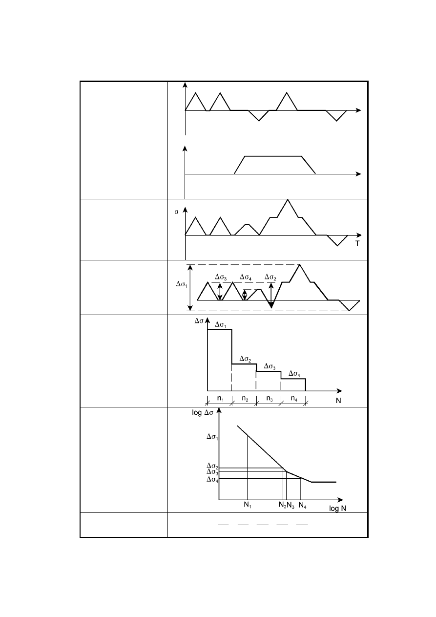
EN 1993-1-9 : 2005 (E)
32
a) Loading sequence:
Typical load cycle
(repeated n-times in the
design life)
T
P
1
T
P
2
b) Stress history at detail
c) Cycle counting (e.g.
reservoir method)
d) Stress range spectrum
e) Cycles to failure
f) Damage summation
(Palmgren-Miner rule)
¦
d
L
4
4
3
3
2
2
1
1
i
i
D
N
n
N
n
N
n
N
n
N
n
Figure A.1: Cumulative damage method
BS EN 1993-1-9 : 2005
Licensed copy: BSI USER 06 Document Controller, Midmac Contracting Co. W.L.L, Version correct as of 05/06/2011 14:51, (c) BSI
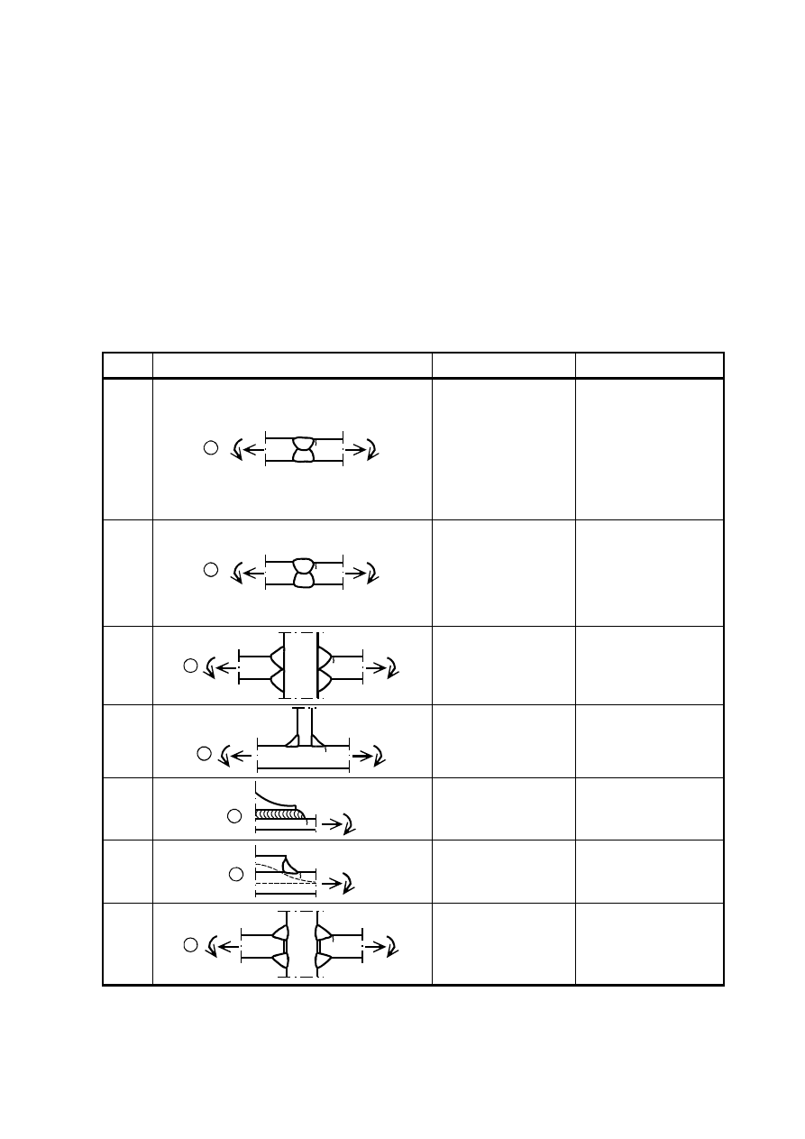
EN 1993-1-9 : 2005 (E)
33
Annex B [normative] – Fatigue resistance using the geometric (hot spot)
stress method
(1)
For the application of the geometric stress method detail categories are given in Table B.1 for cracks
initiating from
–
toes of butt welds,
–
toes of fillet welded attachments,
–
toes of fillet welds in cruciform joints.
Table B.1: Detail categories for use with geometric (hot spot) stress method
Detail
category
Constructional detail
Description
Requirements
112
1
1) Full penetration butt joint.
1)
- All welds ground flush to plate
surface parallel to direction of
the arrow.
- Weld run-on and run-off pieces
to be used and subsequently
removed, plate edges to be
ground flush in direction of
stress.
- Welded from both sides,
checked by NDT.
- For misalignment see NOTE 1.
100
2
2) Full penetration butt joint.
2)
- Weld not ground flush
- Weld run-on and run-off pieces
to be used and subsequently
removed, plate edges to be
ground flush in direction of
stress.
- Welded from both sides.
- For misalignment see NOTE 1.
100
3
3) Cruciform joint with full
penetration K-butt welds.
3)
- Weld toe angle 60°.
- For misalignment see NOTE 1.
100
4
4) Non load-carrying fillet
welds.
4)
- Weld toe angle 60°.
- See also NOTE 2.
100
5
5) Bracket ends, ends of
longitudinal stiffeners.
5)
- Weld toe angle 60°.
- See also NOTE 2.
100
6
6) Cover plate ends and similar
joints.
6)
- Weld toe angle 60°.
- See also NOTE 2.
90
7
7) Cruciform joints with load-
carrying fillet welds.
7)
- Weld toe angle 60°.
- For misalignment see NOTE 1.
- See also NOTE 2.
NOTE 1 Table B.1 does not cover effects of misalignment. They have to be considered explicitly in
determination of stress.
NOTE 2 Table B.1 does not cover fatigue initiation from the root followed by propagation through
the throat.
BS EN 1993-1-9 : 2005
Licensed copy: BSI USER 06 Document Controller, Midmac Contracting Co. W.L.L, Version correct as of 05/06/2011 14:51, (c) BSI

EN 1993-1-9 : 2005 (E)
34
NOTE 3 For the definition of the weld toe angle see EN 1090.
BS EN 1993-1-9 : 2005
Licensed copy: BSI USER 06 Document Controller, Midmac Contracting Co. W.L.L, Version correct as of 05/06/2011 14:51, (c) BSI

blank
Licensed copy: BSI USER 06 Document Controller, Midmac Contracting Co. W.L.L, Version correct as of 05/06/2011 14:51, (c) BSI

D
<$E/0
!#< &
6&%**?6&
')**+,-.,/0010,,8
23)**+,-.,/0014,,8
";
!
""
"#""
""$
%"
"""
&'(
)**+,-.,/0010,,,23()**+,-.,/0014*,,
""56
"
7&
!"'()**+,-.,/0010,,823()**+,-.,/001
4,,8"(9":";
"%(;;";
&
""&
$
"&
6'<3
="
!"!'(
)**+,-.,/001488823()**+,-.,/0014,*/"(9"
""#"
2
>"?"'()**+,-.,
/0014,,.23()**+,-.,/0014,,8"(""9"
"
7(;;";76
2"(;;
"
!&
&@3
"!&A5?80//3"
&"""
"B&&B
""
'&""&
"&@&
""
""
A"!6>
'()**+,-.,/0014,4,"(9"
BS EN
1993-1-9:2005
Licensed copy: BSI USER 06 Document Controller, Midmac Contracting Co. W.L.L, Version correct as of 05/06/2011 14:51, (c) BSI
Wyszukiwarka
Podobne podstrony:
Eurocode 3 Part 1 7 2009 Design of Steel Structures Plated Structures Subject to Out of Plane Loa
Eurocode 3 Part 1 4 2006 Design of Steel Structures General rules Supplementary Rules for Stainl
Eurocode 3 Part 1 5 2009 Design of Steel Structures Plated Structural Elements
Eurocode 3 Part 3 2 2006 Design of Steel Structures Towers, Masts and Chimneys Chimneys
Eurocode 3 Part 1 9 2005 UK NA Design of Steel Structures Fatigue
Eurocode 2 Part 3 2006 Design of concrete structures Liquid retaining and containing structures
Eurocode 3 Part 1 11 2005 UK NA Design of Steel Structures Design of Structures with Tension Com
Eurocode 3 Part 1 2 2005 UK NA Design of steel structures General rules Structural fire design
Eurocode 6 Part 1 2 1996 2005 Design of Masonry Structures General Rules Structural Fire Design
Eurocode 3 Part 2 2006 UK NA Design of steel structures Steel bridges
Eurocode 3 Part 1 12 2007 UK NA Design of Steel Structures Additional Rules for the Extension of
Eurocode 3 Part 1 3 2006 UK NA Design of steel structures General rules Supplementary rules for
Eurocode 3 Part 1 11 2006 Design of Steel Structures Design of Structures With Tension Components
Eurocode 3 Part 1 12 2007 Design of Steel Structures Additional Rules for the Extension of EN 199
Eurocode 6 Part 1 1 1996 2005 Design of Masonry Structures General Rules for Reinforced and Unre
Eurocode 5 EN 1995 1 1 Design Of Timber Structures Part 1 1 General Rules
Eurocode 5 EN 1995 1 1 Design Of Timber Structures Part 1 1 General Rules
Eurocode 8 Part 6 1998 2005 Design of Structures for Earthquake Resistance Towers, Masts and Ch
Eurocode 9 Part 1 3 1999 2007 Design of Aluminium Structures Structures Susceptible to Fatigue
więcej podobnych podstron