BRITISH STANDARD
BS EN
1993-1-4:2006
Eurocode 3 — Design of
steel structures —
Part 1-4: General rules —
Supplementary rules for stainless steels
The European Standard EN 1993-1-4:2006 has the status of a
British Standard
ICS 91.040.01; 91.080.10
12&23<,1*:,7+287%6,3(50,66,21(;&(37$63(50,77('%<&23<5,*+7/$:
Licensed copy: BSI USER 06 Document Controller, Midmac Contracting Co. W.L.L, Version correct as of 26/05/2010
14:00, (c) BSI

BS EN 1993-1-4:2006
This British Standard was
published under the authority
of the Standards Policy and
Strategy Committee
on 30 November 2006
© BSI 2006
ISBN 0 580 49666 X
National foreword
This British Standard was published by BSI. It is the UK implementation of
EN 1993-1-4:2006.
The UK participation in its preparation was entrusted by Technical Committee
B/525, Building and civil engineering structures, to Subcommittee B/525/31,
Structural use of steel.
A list of organizations represented on B/525/31 can be obtained on request to
its secretary.
The structural Eurocodes are divided into packages by grouping Eurocodes for
each of the main materials: concrete, steel, composite concrete and steel,
timber, masonry and aluminium; this is to enable a common date of
withdrawal (DOW) for all the relevant parts that are needed for a particular
design. The conflicting national standards will be withdrawn at the end of the
coexistence period, after all the EN Eurocodes of a package are available.
Following publication of the EN, there is a period allowed for national
calibration during which the National Annex is issued, followed by a
coexistence period of a maximum three years. During the coexistence period
Member States are encouraged to adapt their national provisions. Conflicting
national standards will be withdrawn by March 2010 at the latest. Where a
normative part of this EN allows for a choice to be made at national level, the
range and possible choice will be given in the normative text, and a note will
qualify it as a Nationally Determined Parameter (NDP). NDPs can be a specific
value for a factor, a specific level or class, a particular method or a particular
application rule if several are proposed in the EN. To enable EN 1993-1-4 to be
used in the UK, the NDPs will be published in a National Annex, which will be
made available by BSI in due course after public consultation has taken place.
This publication does not purport to include all the necessary provisions of a
contract. Users are responsible for its correct application.
Compliance with a British Standard cannot confer immunity from
legal obligations.
Amendments issued since publication
Amd. No.
Date
Comments
Licensed copy: BSI USER 06 Document Controller, Midmac Contracting Co. W.L.L, Version correct as of 26/05/2010
14:00, (c) BSI

EUROPEAN STANDARD
NORME EUROPÉENNE
EUROPÄISCHE NORM
EN 1993-1-4
October 2006
ICS 91.040.01; 91.080.10
Supersedes ENV 1993-1-4:1996
English Version
Eurocode 3 - Design of steel structures - Part 1-4: General rules
- Supplementary rules for stainless steels
Eurocode 3 - Calcul des structures en acier - Partie 1-4:
Règles générales - Règles supplémentaires pour les aciers
inoxydables
Eurocode 3 - Bemessung und Konstruktion von
Stahlbauten - Teil 1-4: Allgemeine Bemessungsregeln -
Ergänzende Regeln zur Anwendung von nichtrostender
Stählen
This European Standard was approved by CEN on 9 January 2006.
CEN members are bound to comply with the CEN/CENELEC Internal Regulations which stipulate the conditions for giving this European
Standard the status of a national standard without any alteration. Up-to-date lists and bibliographical references concerning such national
standards may be obtained on application to the Central Secretariat or to any CEN member.
This European Standard exists in three official versions (English, French, German). A version in any other language made by translation
under the responsibility of a CEN member into its own language and notified to the Central Secretariat has the same status as the official
versions.
CEN members are the national standards bodies of Austria, Belgium, Cyprus, Czech Republic, Denmark, Estonia, Finland, France,
Germany, Greece, Hungary, Iceland, Ireland, Italy, Latvia, Lithuania, Luxembourg, Malta, Netherlands, Norway, Poland, Portugal, Romania,
Slovakia, Slovenia, Spain, Sweden, Switzerland and United Kingdom.
EUROPEAN COMMITTEE FOR STANDARDIZATION
C O M I T É E U R O P É E N D E N O R M A L I S A T I O N
E U R O P Ä I S C H E S K O M I T E E F Ü R N O R M U N G
Management Centre: rue de Stassart, 36 B-1050 Brussels
© 2006 CEN
All rights of exploitation in any form and by any means reserved
worldwide for CEN national Members.
Ref. No. EN 1993-1-4:2006: E
Licensed copy: BSI USER 06 Document Controller, Midmac Contracting Co. W.L.L, Version correct as of 26/05/2010
14:00, (c) BSI

EN 1993-1-4: 2006 (E)
2
Contents
Page
Foreword
3
1
General
4
1.1 Scope
4
1.2
Normative references
4
1.3
Assumptions
5
1.4
Distinction between principles and application rules
5
1.5
Definitions
5
1.6
Symbols
5
2
Materials
6
2.1
Structural stainless steels
6
2.2
Bolts
8
2.3
Welding consumables
9
3
Durability
9
4
Serviceability limit states
10
4.1
General
10
4.2
Determination of deflections
10
5
Ultimate limit states
12
5.1
General
12
5.2
Classification of cross-sections
12
5.3
Resistance of cross-sections
17
5.4
Buckling resistance of members
18
5.5
Uniform members in bending and axial compression
20
5.6
Shear resistance
21
5.7
Transverse web stiffeners
21
6
Connection design
22
6.1
General
22
6.2
Bolted connections
22
6.3
Design of welds
23
7
Design assisted by testing
23
8
Fatigue
23
9
Fire resistance
23
Annex A [informative] Durability
24
A.1 Introduction
24
A.2
Types of corrosion
25
A.3
Levels of risk
27
A.4
Selection of materials
27
A.5
Design for corrosion control
30
A.6
Connections
31
Annex B [informative] Stainless steel in the work hardened condition
34
B.1
General
34
B.2
Work hardening from cold rolling
34
B.3
Work hardening from fabrication
34
Annex C [informative] Modelling of material behaviour
35
C.1
General
35
C.2
Material properties
35
Licensed copy: BSI USER 06 Document Controller, Midmac Contracting Co. W.L.L, Version correct as of 26/05/2010
14:00, (c) BSI

EN 1993-1-4: 2006 (E)
3
Foreword
This European Standard EN 1993-1-4, Eurocode 3: Design of steel structures: Part 1-4 General Rules –
Supplementary rules for stainless steels, has been prepared by Technical Committee CEN/TC250 « Structural
Eurocodes », the Secretariat of which is held by BSI. CEN/TC250 is responsible for all Structural Eurocodes.
This European Standard shall be given the status of a National Standard, either by publication of an identical
text or by endorsement, at the latest by April 2007 and conflicting National Standards shall be withdrawn
at latest by March 2010.
This Eurocode supersedes ENV 1993-1-4.
According to the CEN-CENELEC Internal Regulations, the National Standard Organizations of the
following countries are bound to implement this European Standard: Austria, Belgium, Cyprus, Czech
Republic, Denmark, Estonia, Finland, France, Germany, Greece, Hungary, Iceland, Ireland, Italy, Latvia,
Lithuania, Luxembourg, Malta, Netherlands, Norway, Poland, Portugal, Romania, Slovakia, Slovenia, Spain,
Sweden, Switzerland and United Kingdom.
National Annex for EN 1993-1-4
This standard gives alternative procedures, values and recommendations with notes indicating where national
choices may have to be made. The National Standard implementing EN 1993-1-4 should have a National
Annex containing all Nationally Determined Parameters to be used for the design of steel structures to be
constructed in the relevant country.
National choice is allowed in EN 1993-1-4 through clauses:
–
2.1.4(2)
–
2.1.5(1)
–
5.1(2)
–
5.5(1)
–
5.6(2)
–
6.1(2)
–
6.2(3)
Licensed copy: BSI USER 06 Document Controller, Midmac Contracting Co. W.L.L, Version correct as of 26/05/2010
14:00, (c) BSI

EN 1993-1-4: 2006 (E)
4
1 General
1.1 Scope
(1)
This Part 1.4 of EN
1993 gives supplementary provisions for the design of buildings and civil
engineering works that extend and modify the application of EN
1993-1-1, EN
1993-1-3, EN 1993-1-5 and EN
1993-1-8 to austenitic, austenitic-ferritic and ferritic stainless steels.
NOTE 1:
Information on the durability of stainless steels is given in Annex A.
NOTE 2:
The execution of stainless steel structures is covered in EN 1090.
NOTE 3:
Guidelines for further treatment, including heat treatment, are given in EN 10088.
1.2 Normative references
This following normative documents contain provisions which, through reference to this text, constitute
provisions of this European Standard. For dated references, subsequent amendments to or revisions of any of
these publications do not apply. However, parties to agreements based on this European Standard are
encouraged to investigate the possibility of applying the most recent editions of the normative documents
indicated below. For undated references, the latest edition of the normative document referred to applies.
EN 1990
Eurocode 0: Basis of structural design
EN 508-3
Roofing products from metal sheet. Specification for self-supporting products of steel,
aluminium or stainless steel sheet. Stainless steel;
EN 1090-2
Execution of steel structures and aluminium structures – Part 2: Technical requirements
for steel structures;
EN 1993-1-1
Design of steel structures: General rules and rules for buildings;
EN 1993-1-2
Design of steel structures: Structural fire design;
EN 1993-1-3
Design of steel structures: Cold formed thin gauge members and sheeting;
EN 1993-1-5
Design of steel structures: Plated structural elements;
EN 1993-1-6
Design of steel structures: Strength and stability of shell structures;
EN 1993-1-8
Design of steel structures: Design of joints;
EN 1993-1-9
Design of steel structures: Fatigue;
EN 1993-1-10
Design of steel structures: Material toughness and through-thickness properties;
EN 1993-1-11
Design of steel structures: Design of structures with tension components made of steel;
EN 1993-1-12
Design of steel structures: Additional rules for the extension of EN 1993 up to steel grades
S 700;
EN ISO 3506-1
Mechanical properties of corrosion resistant stainless steel fasteners – Part 1: Bolts,
screws and studs;
EN ISO 3506-2
Mechanical properties of corrosion resistant stainless steel fasteners – Part 2: Nuts
EN ISO 3506-3
Mechanical properties of corrosion resistant stainless steel fasteners – Part 3: Set screws
and similar fasteners under tensile tests;
EN ISO 7089
Plain washers - Normal series - Product grade A;
EN ISO 7090
Plain washers, chamfered - Normal series - Product grade A;
EN ISO 9445
Continuously cold-rolled stainless steel narrow strip, wide strip, plate/sheet and cut lengths
- Tolerances on dimensions and form
EN 10029
Specification for tolerances on dimensions, shape and mass for hot rolled steel plates
3 mm thick or above;
Licensed copy: BSI USER 06 Document Controller, Midmac Contracting Co. W.L.L, Version correct as of 26/05/2010
14:00, (c) BSI

EN 1993-1-4: 2006 (E)
5
EN
10052
Vocabulary of heat treatment terms for ferrous products;
EN
10088-1
Stainless steels – Part 1: List of stainless steels;
EN 10088-2
Stainless steels – Part 2: Technical delivery conditions for sheet/plate and strip for
general purposes;
EN 10088-3
Stainless steels - Part 3: Technical delivery conditions for semi-finished products, bars,
rods and sections for general purposes;
EN 10162
Cold rolled steel sections. Technical delivery conditions. Dimensional and cross-sectional
tolerances;
EN 10219-2
Cold formed welded structural sections of non-alloy and fine grain steels. Tolerances,
dimensions and sectional properties;
1.3 Assumptions
(1)
In addition to the general assumptions of EN 1990 the following assumptions apply:
- fabrication and erection complies with EN 1090-2.
1.4 Distinction between principles and application rules
(1) The rules in EN 1990 clause 1.4 apply.
1.5 Definitions
(1)
The rules in EN 1990 clause 1.5 apply.
(2)
Unless otherwise stated, the vocabulary of treatment terms for ferrous products used in EN
10052
applies.
1.6 Symbols
In addition to those given in EN 1990, EN 1993-1-1, EN 1993-1-3, EN 1993-1-5 and 1993-1-8, the following
symbols are used:
f
u,red
reduced value of bearing strength
E
s,ser
secant modulus of elasticity used for serviceability limit state calculations
E
s,1
secant modulus corresponding to the stress in the tension flange
E
s,2
secant modulus corresponding to the stress in the compression flange
σ
1,Ed,ser
serviceability design stress
n
coefficient
Licensed copy: BSI USER 06 Document Controller, Midmac Contracting Co. W.L.L, Version correct as of 26/05/2010
14:00, (c) BSI

EN 1993-1-4: 2006 (E)
6
2 Materials
2.1 Structural stainless steels
2.1.1 General
(1)
The provisions given in this Part 1.4 should be applied only to design using austenitic, austenitic-ferritic
and ferritic stainless steels.
(2)
The nominal values of the material properties given in 2.1.2 should be used as characteristic values in
structural design calculations.
(3)
For further information about material properties reference should be made to EN
10088.
(4)
The design provisions specified in this Part 1.4 are applicable for material of nominal yield strength f
y
up to and including 480
N/mm
2
.
NOTE: Rules for the use of work hardened material with f
y
> 480 N/mm
2
are given in Informative
Annex B.
(5)
The higher strength of other materials (see 2.1.2 and Annex B) may be taken into account in the design
provided that doing so is justified by appropriate tests in accordance with Section 7.
2.1.2 Material properties for stainless steel
(1)
In design calculations the values should be taken as follows, independent of the direction of rolling:
-
yield strength f
y
: the nominal stress (0,2% proof stress) specified in Table 2.1;
-
ultimate tensile strength f
u
: the nominal ultimate tensile strength specified in Table 2.1.
(2)
The ductility requirements in EN 1993-1-1, clause 3.2.2 also apply to stainless steels. Steels conforming
with one of the steel grades listed in Table 2.1 should be accepted as satisfying these requirements.
(3)
For structural hollow sections, the strength values given in Table 2.1 for the relevant product form of the
base material (cold-rolled strip, hot rolled strip or hot rolled plate) should be used.
(4)
Higher strength values derived from cold working the base material may be used in design provided they
are verified by tests on coupons taken from the structural hollow section in accordance with Section 7.
(5)
For cold worked material, the material tests given in the material certificate required according to EN
1090, should be in such a direction that the strength values used in design are independent of the direction of
rolling or stretching.
Licensed copy: BSI USER 06 Document Controller, Midmac Contracting Co. W.L.L, Version correct as of 26/05/2010
14:00, (c) BSI
EN 1993-1-4: 2006 (E)
7
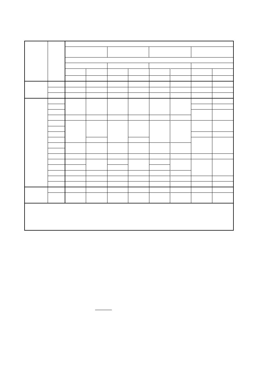
Table 2.1: Nominal values of the yield strength f
y
and the ultimate tensile strength
f
u
for structural stainless steels to EN 10088
1)
Product form
Cold rolled strip
Hot rolled strip
Hot rolled plate
Bars, rods and
sections
Nominal thickness t
t
≤ 6 mm
t
≤ 12 mm
t
≤ 75 mm
t
≤ 250 mm
f
y
f
u
f
y
f
u
f
y
f
u
f
y
f
u
Type of
stainless
steel
Grade
N/mm
2
N/mm
2
N/mm
2
N/mm
2
N/mm
2
N/mm
2
N/mm
2
N/mm
2
1.4003
280
450
280
450
250
3)
450
3)
260
4)
450
4)
1.4016
260
450
240
450
240
3)
430
3)
240
4)
400
4)
Ferritic
steels
1.4512
210
380
210
380
-
-
-
-
1.4306
180
460
1.4307
175
450
1.4541
220
520
200
520
200
500
1.4301
230
540
210
520
210
520
190
500
1.4401
1.4404
200
500
1.4539
530
530
230
530
1.4571
240
540
220
540
220
520
1.4432
1.4435
240
550
220
550
220
520
200
500
1.4311
290
550
270
550
270
550
270
550
1.4406
300
280
280
1.4439
290
580
270
580
270
580
1.4529
300
650
300
650
300
650
280
580
1.4547
320
650
300
650
300
650
300
650
Austenitic
steels
1.4318
350
650
330
650
330
630
-
-
1.4362
420
600
400
600
400
630
400
2)
600
2)
Austenitic
-ferritic
steels
1.4462
480
660
460
660
460
640
450
650
1)
The nominal values of f
y
and f
u
given in this table may be used in design without taking special account of
anisotropy or strain hardening effects.
2)
t
≤ 160 mm
3)
t
≤ 25 mm
4)
t
≤ 100 mm
2.1.3 Design values of material coefficients
(1)
The following values of the material coefficients may be assumed for the global analysis and in
determining the resistances of members and cross-sections:
-
Modulus of elasticity, E:
E
= 200 000 N/mm
2
for the austenitic and austenitic-ferritic grades in Table 2.1 excluding grades
1.4539, 1.4529 and 1.4547
E
= 195 000 N/mm
2
for the austenitic grades 1.4539, 1.4529 and 1.4547
E
= 220 000 N/mm
2
for the ferritic grades in Table 2.1
-
Shear modulus, G, where
)
1
(
2
ν
+
=
E
G
-
Poisson’s ratio in elastic stage,
3
,
0
=
ν
Licensed copy: BSI USER 06 Document Controller, Midmac Contracting Co. W.L.L, Version correct as of 26/05/2010
14:00, (c) BSI

EN 1993-1-4: 2006 (E)
8
Alternatively, stress-strain curves according to Annex C may be used for materials in the annealed condition to
describe the material behaviour.
(2)
For calculating deflections in individual members, the secant modulus appropriate to the stress in the
member at the serviceability limit state may be used, see 4.2(5).
2.1.4 Fracture toughness
(1)
The austenitic and austenitic-ferritic stainless steels covered in this Part 1.4 may be assumed to be
adequately tough and not susceptible to brittle fracture for service temperatures down to -40
°C.
NOTE: Austenitic steels may also be used for temperatures below -40
°C, but the requirements should be
determined for each particular case.
NOTE: See Annex A.5.3 concerning embrittlement due to contact with zinc in fire.
(2)
For ferritic stainless steels, the rules in EN 1993-1-10 give guidance. Required testing temperature and
required CVN-values may be determined from Table 2.1 of EN 1993-1-10.
NOTE 1: Ferritic steels are not classified into sub-grades.
NOTE 2: The National Annex may provide further information on fracture toughness of ferritic stainless steels.
2.1.5 Through-thickness properties
(1)
Guidance on the choice of through-thickness properties is given in EN 1993-1-10.
NOTE: The National Annex may provide further information on the choice of through thickness properties.
2.1.6 Tolerances
(1)
The dimensional and mass tolerances of rolled steel sections, structural hollow sections and plates
should conform with the relevant product standard unless more severe tolerances are specified.
NOTE: For information about tolerances for thickness of cold rolled stainless steel, reference should be made to
EN ISO 9445: 2006. For plates see EN 10029
(2)
For welded components the tolerances given in EN 1090-2 should be applied.
(3)
For structural analysis and design, the nominal values of dimensions should be used except that the
design thickness of strips should be determined according to 3.2.4(3) of EN 1993-1-3.
2.2 Bolts
2.2.1 General
(1)
Stainless steel bolts and nuts should conform with EN ISO
3506 - 1,2,3. Washers should be of stainless
steel and should conform with EN ISO
7089 or EN ISO
7090, as appropriate. The corrosion resistance of the
bolts should be equivalent to, or better than, the corrosion resistance of the parent material.
(2)
The nominal yield strength f
yb
and ultimate tensile strength f
ub
for stainless steel bolts should be
obtained from Table 2.2.
(3)
Pending the issue of an appropriate European Standard, the specified properties should be verified using
a recognised quality control system, with samples from each batch of fasteners.
Licensed copy: BSI USER 06 Document Controller, Midmac Contracting Co. W.L.L, Version correct as of 26/05/2010
14:00, (c) BSI
EN 1993-1-4: 2006 (E)
9
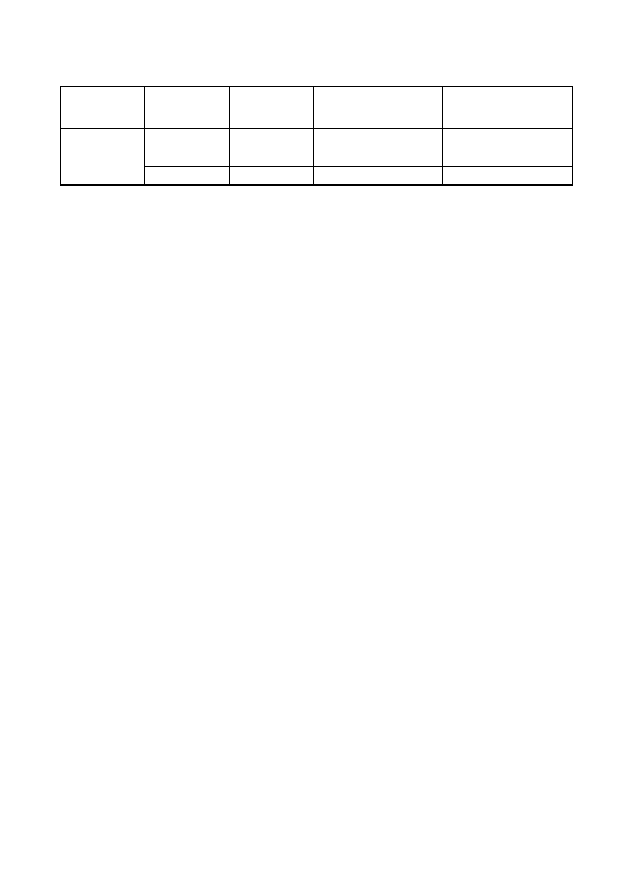
Table 2.2: Nominal values of f
yb
and f
ub
for stainless steel bolts
Material
groups
Property class
to
EN ISO
3506
Range of sizes
Yield strength
f
yb
N/mm
2
Ultimate tensile strength
f
ub
N/mm
2
50
≤
M 39
210
500
70
≤
M 24
450
700
Austenitic
and
austenitic-
ferritic
80
≤
M 24
600
800
2.2.2 Preloaded bolts
NOTE: High strength bolts made of stainless steel should not be used as preloaded bolts designed for a specific slip
resistance, unless their acceptability in a particular application can be demonstrated from test results.
2.2.3 Other types of mechanical fastener
(1)
Requirements for other types of mechanical fasteners are given in EN 1993-1-3.
2.3 Welding consumables
(1)
General requirements for welding consumables are given in EN 1993-1-8.
(2) In addition to the requirements of EN 1993-1-8, the welding electrodes should be capable of producing a
weld with a corrosion resistance that is adequate for the service environment, provided that the correct welding
procedure is used.
(3)
The welding electrodes may be assumed to be adequate if the corrosion resistance of the deposited metal
and weld metal is not less than that of the material to be welded.
NOTE: Professional advice is recommended on the selection of welding procedure for jointing stainless steels
3 Durability
(1)
The requirements for durability given in Section 4 of EN
1993-1-1 should also be applied for stainless
steels.
(2)
An appropriate grade of stainless steel should be selected according to the corrosion resistance required
for the environment in which the structural members are to be used.
NOTE: Guidance on the selection of materials for corrosion resistance is given in Annex A.
(3)
In cosmetic applications, the possible minor changes in surface appearance that might take place as a
result of dirt deposits (which in adverse circumstances can create crevices and lead to surface micro-pitting)
should also be taken into account. A suitable corrosion-resistant grade of stainless steel should be used to
ensure that only superficial surface attack takes place within the design life of the component.
NOTE: Surface aspect features of hot rolled plates are described in EN 10163.
(4)
If necessary, a suitable cleaning regime should be specified to maintain surface appearance.
(5)
Although, under benign atmospheric exposure conditions, the requirements given in (3) can be satisfied
by most stainless steels, expert advice should be sought if stainless steel is required to be exposed to
environments that contain chemicals, including atmospheres associated with certain industrial processes, in
swimming pool buildings, sea water and salt spray from road de-icing or the like.
Licensed copy: BSI USER 06 Document Controller, Midmac Contracting Co. W.L.L, Version correct as of 26/05/2010
14:00, (c) BSI

EN 1993-1-4: 2006 (E)
10
NOTE: Additional information on design for corrosion control is given in Annex A.
4 Serviceability limit states
4.1 General
(1)
The requirements for serviceability given in Section 7 of EN
1993-1-1 should be applied for stainless
steels.
(2)
Deflections in members should be estimated in accordance with 4.2.
4.2 Determination of deflections
(1)
The effects of the non-linear stress-strain behaviour of stainless steels, and the effectiveness of the cross-
section, should be taken into account in estimating deflections.
NOTE: Guidance for the description of the non-linear material behaviour of annealed material is given in
Informative Annex C.
(2)
The basic requirements for serviceability limit states are given in clause 3.4 of EN 1990.
NOTE: EN 1990 gives the appropriate combinations of actions to use in the following situations:
-
for calculating deflections under permanent and/or variable actions;
-
when long term deformations due to shrinkage, relaxation or creep need to be considered;
-
if the appearance of the structure or the comfort of the user or functioning of machinery are being
considered.
(3)
The effective cross-section may conservatively be based on effective widths of compression elements in
Class 4 cross-sections determined using 5.2.3. Alternatively, the more accurate method in 4.4(4) of EN 1993-1-
5 may be used.
(4)
In the case of members subject to shear lag, the effective cross-section may be based on effective widths
determined using 3.2 in EN 1993-1-5.
(5)
Deflections should be estimated using the secant modulus of elasticity E
s,ser
determined taking account
of the stresses in the member under the load combination for the relevant serviceability limit state and the
orientation of the rolling direction. If the orientation of the rolling direction is not known, or cannot be ensured,
then the value for the longitudinal direction should be used. Alternatively, the FE-methods given in Annex C of
EN 1993-1-5 may be used with the description of the non-linear material behaviour given in Annex C of this
document.
(6)
The value of the secant modulus of elasticity E
s,ser
may be obtained from:
2
)
(
2
,
1
,
,
s
s
ser
s
E
E
E
+
=
(4.1)
where:
E
s,1
is the secant modulus corresponding to the stress
σ
1
in the tension flange;
E
s,2
is the secant modulus corresponding to the stress
σ
2
in the compression flange.
(7)
The values of E
s,1
and E
s,2
for the appropriate serviceability design stress
σ
i
,Ed,ser
and rolling direction
may be estimated using:
Licensed copy: BSI USER 06 Document Controller, Midmac Contracting Co. W.L.L, Version correct as of 26/05/2010
14:00, (c) BSI
EN 1993-1-4: 2006 (E)
11
=
f
002
0
1
y
ser
Ed,
i,
n
ser
Ed,
,
,
σ
σ
i
i
s
E
,
+
E
E
(4.2)
with:
i
= 1 or 2.
(8)
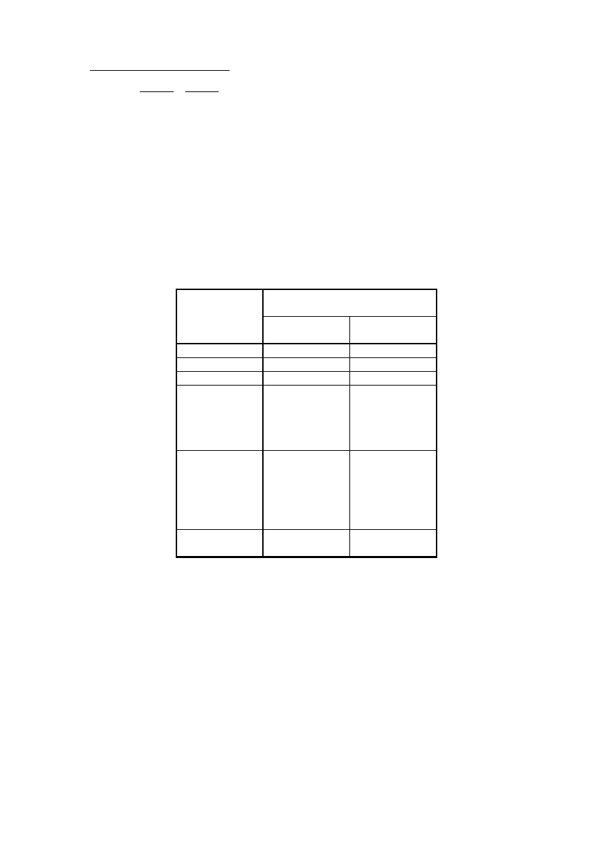
The value of the coefficient n may be taken from Table 4.1.
NOTE: Annex C gives a method for evaluating n for grades other than those listed in Table 4.1.
(9)
As a simplification, the variation of E
s
,ser
along the length of the member may be neglected and the
minimum value of E
s,ser
for that member (corresponding to the maximum values of the stresses
σ
1,Ed,ser
and
σ
2,Ed,ser
in the member) may be used throughout its length.
Table 4.1: Values of n
Coefficient n
Steel grade
Longitudinal
direction
Transverse
direction
1.4003
7
11
1.4016
6
14
1.4512
9
16
1.4301
1.4306
1.4307
1.4318
1.4541
6
8
1.4401
1.4404
1.4432
1.4435
1.4539
1.4571
7
9
1.4462
1.4362
5
5
Licensed copy: BSI USER 06 Document Controller, Midmac Contracting Co. W.L.L, Version correct as of 26/05/2010
14:00, (c) BSI
EN 1993-1-4: 2006 (E)
12
5 Ultimate limit states
5.1 General
(1)
The provisions given in Sections 5 and 6 of EN
1993-1-1 should be applied for stainless steels, except
where modified or superseded by the special provisions given in this Part 1.4.
(2)
The partial factors
γ
M
as defined in 2.4.3 of EN 1993-1-1 are applied to the various characteristic values
of resistance in this section as follows,
see Table 5.1.
Table 5.1: Partial factors
Resistance of cross-sections to excessive yielding including
local buckling
γ
M0
Resistance of members to instability assessed by member
checks
γ
M1
Resistance of cross-sections in tension to fracture
γ
M2
Resistance of bolts, rivets, welds, pins and plates in bearing
γ
M2
NOTE:
γ
M
values may be determined in the National Annex. The following values are recommended
γ
M0
= 1,1
γ
M1
= 1,1
γ
M2
= 1,25
(3)
No rules are given for plastic global analysis.
NOTE: Plastic global analysis should not be used unless there is sufficient experimental evidence to ensure that
the assumptions made in the calculations are representative of the actual behaviour of the structure. In particular
there should be evidence that the joints are capable of resisting the increase in internal moments and forces due to
strain hardening.
(4)P Joints subject to fatigue shall also satisfy the principles given in EN 1993-1-9.
(5)
Where members may be subjected to significant deformation, account may be taken of the potential for
enhanced strength gained through the work hardening properties of austenitic stainless steel. Where this work
hardening increases the actions resisted by the members, the joints should be designed to be consistent with the
increased member resistance, especially where capacity design is required.
5.2 Classification of cross-sections
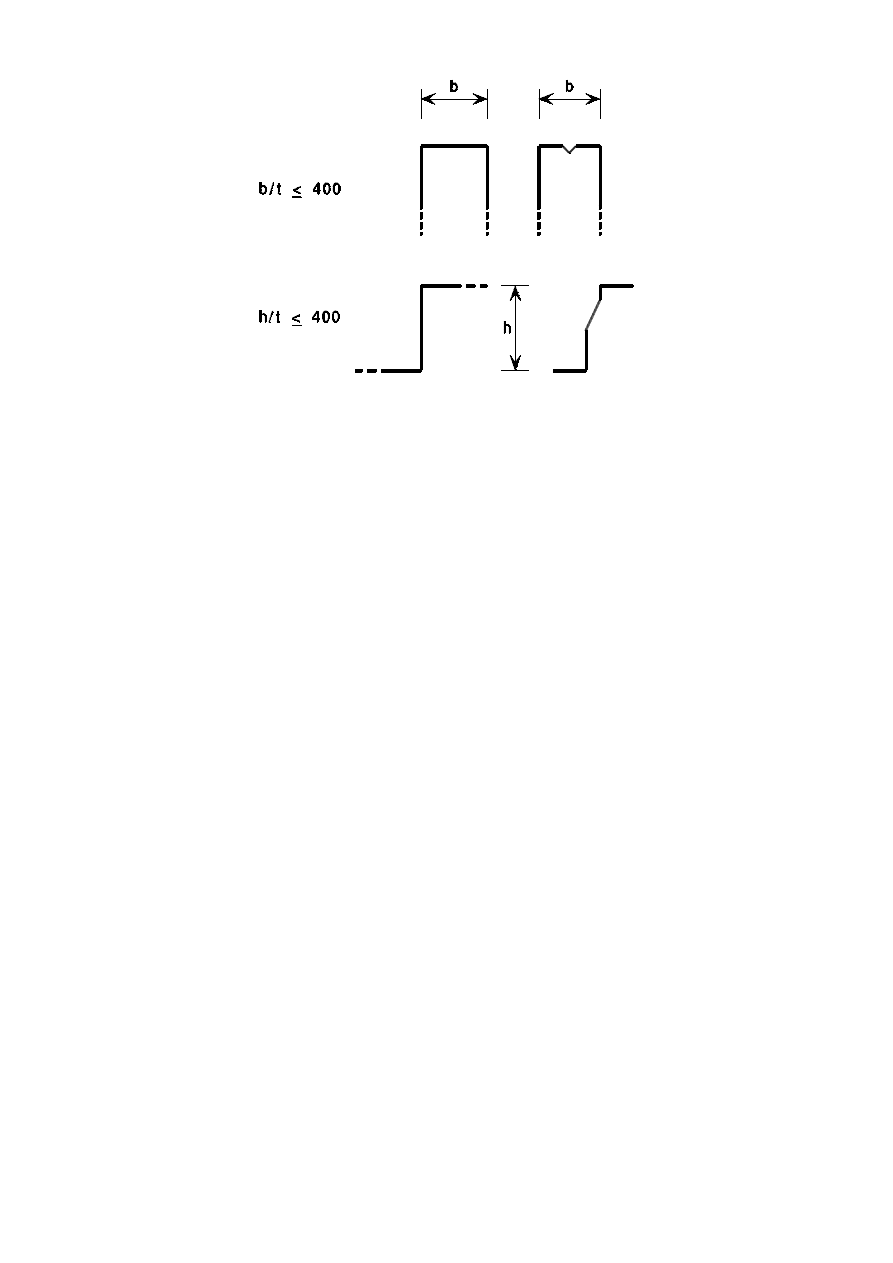
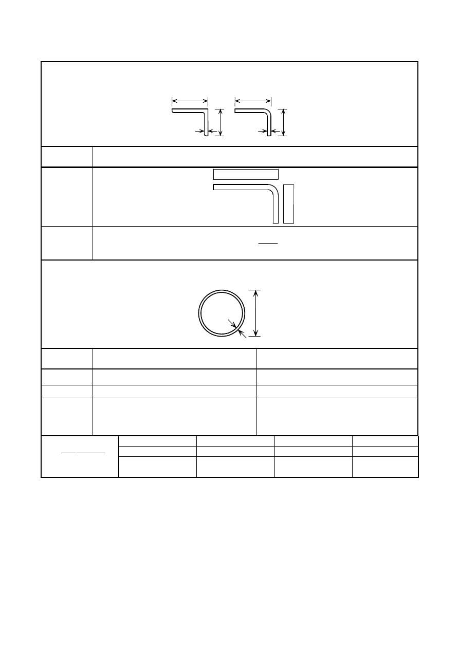
5.2.1 Maximum width-to-thickness ratios
(1)
The provisions for design by calculation given in this Part 1.4 may be assumed to apply to cross-sections
within the dimensional limits given in EN
1993-1-3, except that the overall width-to-thickness ratios b/t and
h/t as defined in EN
1993-1-3 should not exceed 400, see Figure 5.1.
(2)
If visual distortion of flat elements of the cross-section are unacceptable under the serviceability loading,
a limit of b/t
≤ 75 may be applied.
Licensed copy: BSI USER 06 Document Controller, Midmac Contracting Co. W.L.L, Version correct as of 26/05/2010
14:00, (c) BSI
EN 1993-1-4: 2006 (E)
13
Figure 5.1: Maximum width-to-thickness ratios
5.2.2 Classification of compression elements
(1)
Compression elements of cross-sections should be classified as Class 1, 2 or 3 depending upon the limits
specified in Table 5.2. Those compression elements that do not meet the criteria for Class 3 should be
classified as Class 4 elements.
Licensed copy: BSI USER 06 Document Controller, Midmac Contracting Co. W.L.L, Version correct as of 26/05/2010
14:00, (c) BSI
EN 1993-1-4: 2006 (E)
14
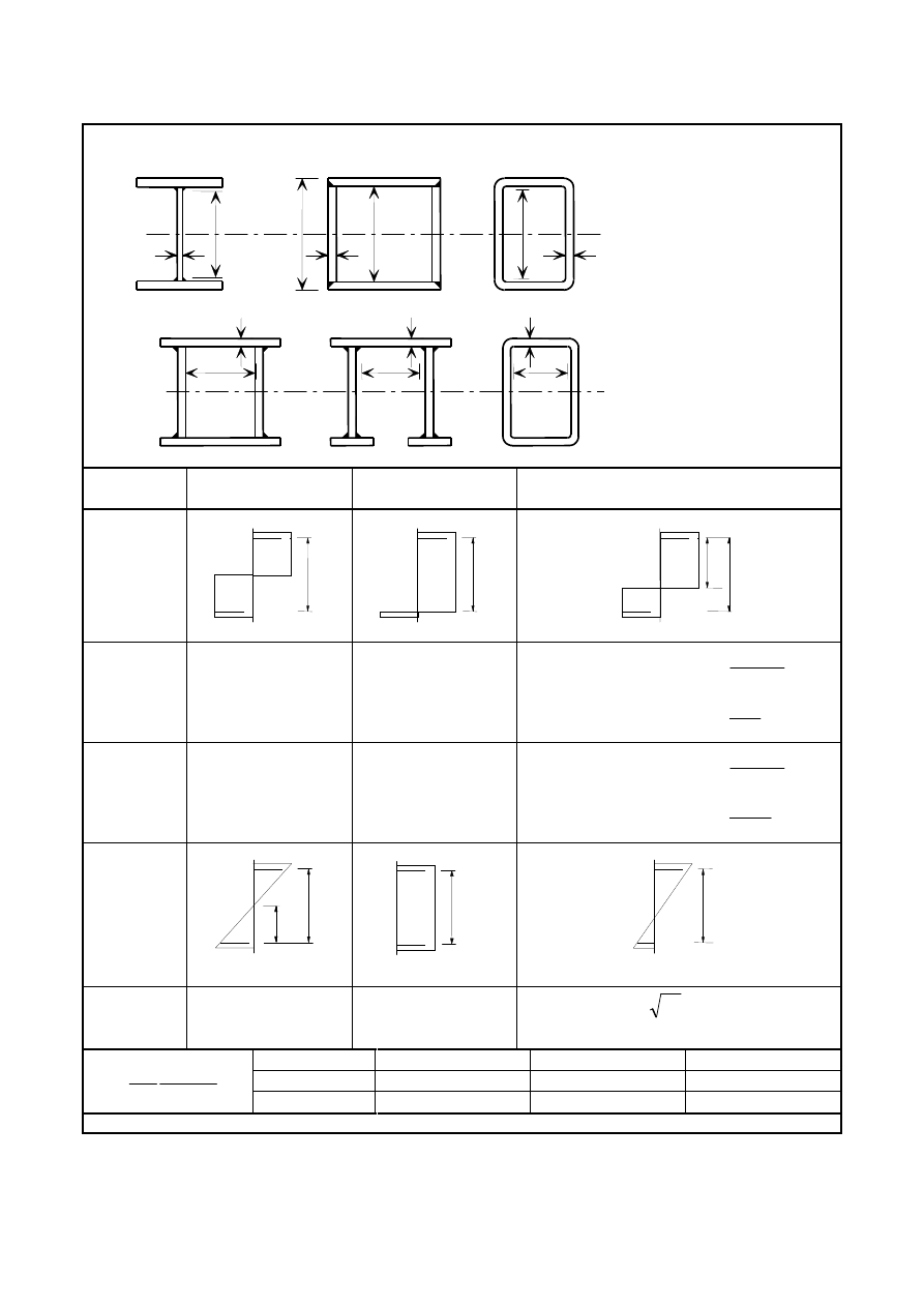
Table 5.2 (sheet 1 of 3): Maximum width-to-thickness ratios for compression parts
Internal compression parts
Class
Part subject to
bending
Part subject to
compression
Part subject to bending and compression
Stress
distribution
in parts
(compression
positive)
1
ε
0
,
56
/
≤
t
c
ε
7
,
25
/
≤
t
c
α
ε
α
α
ε
α
28
/
:
5
,
0
1
13
308
/
:
5
,
0
≤
≤
−
≤
>
t
c
when
t
c
when
2
ε
2
,
58
/
≤
t
c
ε
7
,
26
/
≤
t
c
α
ε
α
α
ε
α
1
,
29
/
:
5
,
0
1
13
320
/
:
5
,
0
≤
≤
−
≤
>
t
c
when
t
c
when
Stress
distribution
in parts
(compression
positive)
3
ε
8
,
74
/
≤
t
c
ε
7
,
30
/
≤
t
c
σ
ε
k
t
c
3
,
15
/
≤
For
σ
k
see EN 1993-1-5
Grade
1.4301
1.4401
1.4462
f
y
(N/mm
2
)
210
220
460
5
,
0
000
210
235
=
E
f
y
ε
ε
1,03
1,01
0,698
Note: For hollow sections, c may conservatively be taken as (h-2t) or (b-2t).
t
c
t
c
Axis of bending
h
c
t
t
c
c
t
c
t
Axis of bending
+
f
y
-
f
y
c
+
f
y
-
f
y
c
+
f
y
-
f
y
c
α
c
+
f
y
-
f
y
c
c
/
2
+
f
y
c
+
f
y
-
ψ
f
y
c
Licensed copy: BSI USER 06 Document Controller, Midmac Contracting Co. W.L.L, Version correct as of 26/05/2010
14:00, (c) BSI
EN 1993-1-4: 2006 (E)
15
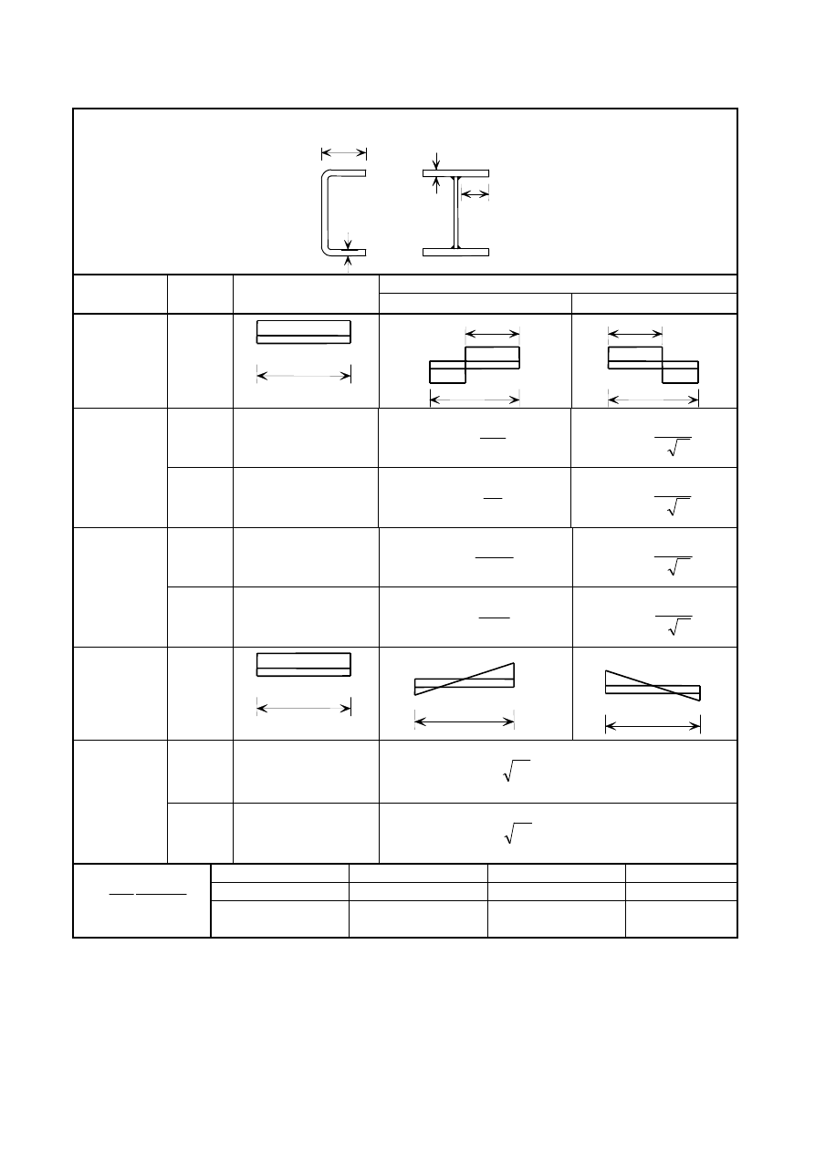
Table 5.2 (sheet 2 of 3): Maximum width-to-thickness ratios for compression parts
Outstand flanges
Part subject to bending and compression
Class
Section
type
Part subject to
compression
Tip in compression
Tip in tension
Stress
distribution in
parts
(compression
positive)
Cold
formed
ε
10
/
≤
t
c
α
ε
10
/
≤
t
c
α
α
ε
10
/
≤
t
c
1
Welded
ε
9
/
≤
t
c
α
ε
9
/
≤
t
c
α
α
ε
9
/
≤
t
c
Cold
formed
ε
4
,
10
/
≤
t
c
α
ε
4
,
10
/
≤
t
c
α
α
ε
4
,
10
/
≤
t
c
2
Welded
ε
4
,
9
/
≤
t
c
α
ε
4
,
9
/
≤
t
c
α
α
ε
4
,
9
/
≤
t
c
Stress
distribution in
parts
(compression
positive)
Cold
formed
ε
9
,
11
/
≤
t
c
σ
ε
k
t
c
1
,
18
/
≤
For k
σ
see EN 1993-1-5
3
Welded
ε
11
/
≤
t
c
σ
ε
k
t
c
7
,
16
/
≤
For k
σ
see EN 1993-1-5
Grade
1.4301
1.4401
1.4462
f
y
(N/mm
2
)
210
220
460
5
,
0
000
210
235
=
E
f
y
ε
ε
1,03
1,01
0,698
c
c
t
t
+
–
c
f
y
c
f
y
f
y
c
α
–
+
c
c
α
f
y
f
y
–
+
+
–
c
f
y
c
f
y
–
+
c
f
y
–
+
Licensed copy: BSI USER 06 Document Controller, Midmac Contracting Co. W.L.L, Version correct as of 26/05/2010
14:00, (c) BSI
EN 1993-1-4: 2006 (E)
16
Table 5.2 (sheet 3 of 3): Maximum width-to-thickness ratios for compression parts
Refer also to “Outstand flanges”
(see sheet 2 of 3)
Angles
Does not apply to angles in
continuous contact with other
components
Class
Section in compression
Stress
distribution
across
section
(compression
positive)
3
ε
ε
1
,
9
2
:
9
,
11
/
≤
+
≤
t
h
b
t
h
Tubular sections
Class
Section in bending
Up to 240 CHS
Section in compression
1
2
50
/
ε
≤
t
d
2
50
/
ε
≤
t
d
2
2
70
/
ε
≤
t
d
2
70
/
ε
≤
t
d
3
2
280
/
ε
≤
t
d
NOTE:
For d > 240 mm and
2
280
/
ε
>
t
d
see EN 1993-1-6.
2
90
/
ε
≤
t
d
NOTE: For
2
90
/
ε
>
t
d
see EN 1993-1-6
.
Grade
1.4301
1.4401
1.4462
f
y
(N/mm
2
)
210
220
460
5
,
0
000
210
235
=
E
f
y
ε
ε
1,03
1,01
0,698
h
b
h
b
t
t
f
y
+
+
d
t
Licensed copy: BSI USER 06 Document Controller, Midmac Contracting Co. W.L.L, Version correct as of 26/05/2010
14:00, (c) BSI
EN 1993-1-4: 2006 (E)
17
5.2.3 Effective widths in Class 4 cross-sections
(1)
In Class 4 cross-sections effective widths may be used to make necessary allowances for reductions in
resistance due to the effects of local buckling using 4.4(1) to (5) of EN 1993-1-5, except that the reduction
factor
ρ
should be taken as follows:
Cold formed or welded internal elements:
2
125
,
0
772
,
0
p
p
λ
λ
ρ
−
=
but ≤ 1
(5.1)
Cold formed outstand elements:
2
231
,
0
1
p
p
λ
λ
ρ
−
=
but ≤ 1
(5.2)
Welded outstand elements:
2
242
,
0
1
p
p
λ
λ
ρ
−
=
but ≤ 1
(5.3)
where
p
λ
is the element slenderness defined as:
σ
ε
λ
k
t
b
p
4
,
28
/
=
in which
t
is the relevant thickness
σ
k
is the buckling factor corresponding to the stress ratio
ψ
and boundary conditions from Table 4.1 or
Table 4.2 in EN 1993-1-5 as appropriate
b
is the relevant width as follows:
b
= d for webs (except RHS)
b
= flat element width for webs of RHS, which can conservatively be taken as h-2t
b
= b for internal flange elements (except RHS)
b
= flat element width for RHS flanges, which can conservatively be taken as b-2t
b
= c for outstand flanges
b
= h for equal leg angles and unequal leg angles
ε
is the material factor defined in Table 5.2.
5.2.4 Effects of shear lag
(1)
The effects of shear lag should be taken into account as specified in 3.3 of EN
1993-1-5.
5.3 Resistance of cross-sections
5.3.1 Tension resistance at holes for bolts
(1)
The tension resistance of a cross-section should be taken as the lesser of the plastic resistance of the
gross cross-section N
pl,Rd
and the ultimate resistance N
u,Rd
of the net cross-section.
Licensed copy: BSI USER 06 Document Controller, Midmac Contracting Co. W.L.L, Version correct as of 26/05/2010
14:00, (c) BSI

EN 1993-1-4: 2006 (E)
18
(2)
The plastic resistance of the gross cross-section should be determined using:
N
pl,Rd
= A
f
y
/
γ
M0
(5.4)
(3)
The ultimate resistance of the net cross-section should be determined from:
N
u,Rd
= k
r
A
net
f
u
/
γ
M2
(5.5)
with:
k
r
= (
1
+ 3
r
(
d
o
/
u
- 0,3
)
)
but k
r
≤
1
r
= [number of bolts at the cross-section]
/
[total number of bolts in the connection]
u
= 2
e
2
but
u
≤
p
2
where:
A
net
is the net cross-sectional area;
d
o
is the nominal diameter of the bolt hole;
e
2
is the edge distance from the centre of the bolt hole to the adjacent edge, in the direction
perpendicular to the direction of load transfer;
p
2
is the spacing centre-to-centre of bolt holes, in the direction perpendicular to the direction of
load transfer.
5.4 Buckling resistance of members
5.4.1 General
(1)
The provisions for flexural, lateral-torsional, torsional, flexural-torsional and distortional buckling given
in EN
1993-1-1 and EN
1993-1-3 as appropriate should be applied for stainless steels except as supplemented
or modified in 5.4.2 or 5.4.3.
NOTE: Clause 6.3.2.3 of EN 1993-1-1 is not applicable to stainless steel.
(2)
The actions should be placed into the formulae in EN 1993-1-1 as absolute values.
χ
min
is the lowest of
the values
χ
y
,
χ
z
,
χ
T
and
χ
TF
where
χ
y
and
χ
z
are calculated on the basis of flexural buckling,
χ
T
is calculated on
the basis of torsional buckling and
χ
TF
is calculated on the basis of torsional-flexural buckling.
5.4.2 Uniform members in compression
5.4.2.1
Buckling curves
(1)
For axial compression in members the value of
χ
for the appropriate non-dimensional slenderness
λ
should be determined from the relevant buckling curve according to:
[
]
1
1
5
,
0
2
2
≤
−
+
=
λ
φ
φ
χ
(5.6)
with
(
)
(
)
2
0
1
5
,
0
λ
λ
λ
α
φ
+
−
+
=
(5.7)
where
cr
y
N
Af
=
λ
for Class 1, 2 and 3 cross-sections
(5.8)
cr
y
eff
N
f
A
=
λ
for Class 4 cross-sections
(5.9)
Licensed copy: BSI USER 06 Document Controller, Midmac Contracting Co. W.L.L, Version correct as of 26/05/2010
14:00, (c) BSI
EN 1993-1-4: 2006 (E)
19
α
is an imperfection factor
N
cr
is the elastic critical force for the relevant buckling mode based on the gross cross sectional
properties.
0
λ
limiting slenderness
(2)
Values for
α
and
0
λ
corresponding to the appropriate buckling curve should be obtained from Table
5.3. The buckling curves in Table 5.3 do not apply to hollow sections which are annealed after fabrication.
(3)
For slenderness
0
λ
λ
≤
or for
2
0
λ
≤
cr
Ed
N
N
the buckling effects may be ignored and only cross
sectional checks apply.
Table 5.3: Values of α
α
α
α and
0
λ
for flexural, torsional and torsional-flexural buckling
Buckling mode
Type of member
α
0
λ
Flexural
Cold formed open sections
0,49
0,40
Hollow sections (welded and seamless)
0,49
0,40
Welded open sections (major axis)
0,49
0,20
Welded open sections (minor axis)
0,76
0,20
Torsional and
torsional-flexural
All members
0,34
0,20
5.4.3 Uniform members in bending
5.4.3.1
Lateral torsional buckling curves
(1)
For bending members of constant cross-section, the value of
χ
LT
for the appropriate non-dimensional
slenderness
LT
λ
should be determined from:
1
1
2
LT
2
LT
LT
LT
≤
−
+
=
λ
φ
φ
χ
(5.10)
in which
(
)
(
)
2
LT
LT
LT
LT
4
,
0
1
5
,
0
λ
λ
α
φ
+
−
+
=
(5.11)
cr
y
M
f
W
y
LT
=
λ
(5.12)
α
LT
is the imperfection factor
= 0,34 for cold formed sections and hollow sections (welded and seamless)
= 0,76 for welded open sections and other sections for which no test data is available
M
cr
is the elastic critical moment for lateral-torsional buckling
(2)
For slendernesses
4
,
0
≤
LT
λ
or for
16
,
0
≤
cr
Ed
M
M
lateral torsional buckling effects may be ignored
and only cross sectional checks apply.
Licensed copy: BSI USER 06 Document Controller, Midmac Contracting Co. W.L.L, Version correct as of 26/05/2010
14:00, (c) BSI

EN 1993-1-4: 2006 (E)
20
5.5 Uniform members in bending and axial compression
(1)
Members which are subjected to combined bending and axial compression should satisfy:
Axial compression and uniaxial major axis moment
To prevent premature buckling about the major axis:
1
/
e
)
(
M1
y
y
pl,
y
W,
Ny
Ed
Ed
y,
min
Rd
b,
Ed
≤
+
+
γ
β
f
W
N
M
k
N
N
y
(5.13)
To prevent premature buckling about the minor axis (for members subject to lateral-torsional buckling):
1
)
(
Rd
b,
Ny
Ed
Ed
y,
1
min
Rd
b,
Ed
≤
+
+
M
e
N
M
k
N
N
LT
(5.14)
Axial compression and uniaxial minor axis moment:
To prevent premature buckling about the minor axis:
1
/
)
(
M1
y
z
pl,
z
W,
Nz
Ed
Ed
z,
min
Rd
b,
Ed
≤
+
+
γ
β
f
W
e
N
M
k
N
N
z
(5.15)
Axial compression and biaxial moments:
All members should satisfy:
1
/
/
)
(
M1
y
z
pl,
z
W,
Nz
Ed
Ed
z,
1
M
y
y
pl,
y
W,
Ny
Ed
Ed
y,
min
Rd
b,
Ed
≤
+
+
+
+
γ
β
γ
β
f
W
e
N
M
k
f
W
e
N
M
k
N
N
z
y
(5.16)
Members potentially subject to lateral-torsional buckling should also satisfy:
1
/
)
(
M1
y
z
pl,
z
W,
Nz
Ed
Ed
z,
Rd
b,
Ny
Ed
Ed
y,
1
min
Rd
b,
Ed
≤
+
+
+
+
γ
β
f
W
e
N
M
k
M
e
N
M
k
N
N
z
LT
(5.17)
In the above expressions:
e
Ny
and e
Nz
are are the shifts in the neutral axes when the cross-section is subject to uniform compression
N
Ed
, M
y,Ed
and M
z,Ed
are the design values of the compression force and the maximum moments about the
y-y and z-z axis along the member, respectively
(N
b,Rd
)
min
is the smallest value of N
b,Rd
for the following four buckling modes: flexural buckling about the
y axis, flexural buckling about the z axis, torsional buckling and torsional-flexural buckling
(N
b,Rd
)
min1
is the smallest value of N
b,Rd
for the following three buckling modes: flexural buckling about
the z axis, torsional buckling and torsional-flexural buckling
β
W,y
and
β
W,z
are the values of
β
W
determined for the y and z axes respectively in which
β
W
= 1,0 for Class 1 or 2 cross-sections
β
W
= W
el
/W
pl
for Class 3 cross-sections
β
W
= W
eff
/W
pl
for Class 4 cross-sections
Licensed copy: BSI USER 06 Document Controller, Midmac Contracting Co. W.L.L, Version correct as of 26/05/2010
14:00, (c) BSI

EN 1993-1-4: 2006 (E)
21
W
pl,y
and W
pl,z
are the plastic moduli for the y and z axes respectively
M
b,Rd
is the lateral-torsional buckling resistance
k
y
, k
z
, k
LT
are the interaction factors
NOTE 1: The National Annex may define k
y
, k
z
, k
LT
. The following values are recommended:
(
)
y
Rd
b
Ed
y
y
N
N
k
,
,
5
,
0
2
0
,
1
−
+
=
λ
but
y
Rd
b
Ed
y
N
N
k
,
,
2
2
,
1
2
,
1
+
≤
≤
(
)
(
)
1
min
,
5
,
0
2
0
,
1
Rd
b
Ed
z
z
N
N
k
−
+
=
λ
but
(
)
1
min
,
2
2
,
1
2
,
1
Rd
b
Ed
z
N
N
k
+
≤
≤
k
LT
=1,0
NOTE 2: The National Annex may give other interaction formulae as alternatives to equations 5.13 to 5.17.
5.6 Shear resistance
(1)
The design shear resistance V
c,Rd
should be taken as the lesser of the shear buckling resistance V
b,Rd
according to 5.2(1) of EN 1993-1-5 modified by (3) and (4) and the plastic shear resistance V
pl,Rd
according to
6.2.6(2) of EN 1993-1-1.
(2) Plates with h
w
/t greater than
ε
η
52
for an unstiffened web or
τ
ε
η
k
23
for a stiffened web should be
checked for resistance to shear buckling and should be provided with transverse stiffeners at the supports.
where h
w
is the clear web depth between flanges, see Figure 5.1 of EN 1993-1-5
ε
is defined in Table 5.2
k
τ
is defined in clause 5.3 of EN 1993-1-5
NOTE: The National Annex may define
η
.
The value
η
= 1,20 is recommended.
(3)
For webs with transverse stiffeners at supports only and for webs with either intermediate transverse or
longitudinal stiffeners or both, the factor
χ
w
for the contribution of the web to shear buckling resistance
should be obtained as follows:
η
χ
=
w
for
η
λ
6
,
0
w
≤
(5.18)
2
w
w
w
05
,
0
64
,
0
11
,
0
λ
λ
χ
−
+
=
for
η
λ
6
,
0
w
>
(5.19)
where
w
λ
is given in clauses 5.3(3) and (5) of EN 1993-1-5
(4)
If the flange resistance is not fully utilised in withstanding the bending moment, i.e.
Rd
f
Ed
M
M
,
<
,
then a factor
χ
f
representing the contribution from the flanges may be included in the shear buckling
resistance.
χ
f
is given in clause 5.4(1) of EN 1993-1-5 but with c given below:
a
f
h
t
f
t
b
c
+
=
yw
2
w
w
yf
2
f
f
5
,
3
17
,
0
and
65
,
0
≤
a
c
(5.20)
5.7 Transverse web stiffeners
Licensed copy: BSI USER 06 Document Controller, Midmac Contracting Co. W.L.L, Version correct as of 26/05/2010
14:00, (c) BSI

EN 1993-1-4: 2006 (E)
22
(1)
The provisions in 9.3 of EN 1993-1-5 apply with additions according to (2) and (3).
(2)
The out-of-plane buckling resistance N
b,Rd
of the stiffener should be determined from 5.4.2 using
α
= 0,49 and
λ
0
= 0,2. The buckling length l of the stiffener should be appropriate for the conditions of
restraint, but not less than 0,75h
w
, where both ends are fixed laterally. A larger value of l should be used for
conditions that provide less end restraint. If the stiffener has a cut-out at the loaded end, its cross sectional
resistance should be checked at the loaded end considering the net area.
(3)
For the buckling check, the effective cross-sectional area of a stiffener should include the stiffener itself
plus a width of web of 11
ε
t
w
either side of the stiffener. At the ends of the member (or openings in the web) the
contributory width to be taken into account should be either 11
ε
t
w
or the existing width, whichever is the
smaller.
6 Connection design
6.1 General
(1)
The provisions given in EN
1993-1-8 should be applied for stainless steels, except where modified or
superseded by the special provisions given in 6.2 and 6.3.
NOTE: Information on durability is given in Annex A. Information on fabrication of connections is given in EN
1090-2.
(2)
The design of connections for stainless steel sheets using self-tapping screws should be in accordance
with EN
1993-1-3 except that the pull-out strength should be determined by testing.
NOTE 1: The ability of the screw to drill and form threads in stainless steel should be demonstrated by tests
unless sufficient experience is available.
NOTE 2: Formulae for pull-out strength based on testing according to Section 7 may be given in the National
Annex.
6.2 Bolted connections
(1)
Bearing strength should be calculated by replacing f
u
by a reduced value f
u,red
given by:
f
u,red
= 0,5
f
y
+ 0,6
f
u
but
≤ f
u
(6.1)
(2
Stainless steel bolts in shear to EN ISO 3506 property classes 50, 70 and 80 should be treated like bolts
grades 4.6, 5.6 and 8.8.
(3)
The shear resistance of a bolt, F
v,Rd
should be determined from the following:
2
ub
,
A
M
Rd
v
f
F
γ
α
=
(6.2)
where
A
is the gross cross-section area of the bolt (if the shear plane passes through unthreaded
portion of the bolt); or the tensile stress area of the bolt (if the shear plane passes through the
threaded portion of the bolt);
f
ub
is the ultimate tensile strength of the bolt, see Table 2.2.
NOTE: The value of
α may be defined in the National Annex. The recommended values are:
- if the shear plane passes through unthreaded portion of the bolt,
α
= 0,6
- if the shear plane passes through the threaded portion of the bolt,
α
= 0,5
Licensed copy: BSI USER 06 Document Controller, Midmac Contracting Co. W.L.L, Version correct as of 26/05/2010
14:00, (c) BSI

EN 1993-1-4: 2006 (E)
23
6.3 Design of welds
(1)
In determining the design resistance of fillet welds, the value of the correlation factor
β
W
should be
taken as 1,0 for all nominal strength classes of stainless steel, unless a lower value is justified by tests in
accordance with Section 7.
7 Design assisted by testing
(1)
Section 5.2 and Annex D of EN 1990 and Section 9 and Annex A of EN
1993-1-3 are applicable to
stainless steels.
(2)
Prototypes for testing should be produced in a similar manner to the components of the final product,
such that they reflect the same levels of work hardening.
(3)
Because stainless steel grades can exhibit anisotropy, the specimens should be prepared from the plate or
sheet in the same orientation (i.e. transverse or parallel to the rolling direction) as intended for the final
structure. If the final orientation is unknown or cannot be guaranteed, tests should be conducted for both
orientations and the less favourable result should be adopted.
8 Fatigue
(1)
For determining the fatigue strength of stainless steel structures, reference should be made to
EN 1993-1-9.
9 Fire resistance
(1)
For structural fire design, material properties at elevated temperatures in Annex C of EN 1993-1-2
should be used.
Licensed copy: BSI USER 06 Document Controller, Midmac Contracting Co. W.L.L, Version correct as of 26/05/2010
14:00, (c) BSI

EN 1993-1-4: 2006 (E)
24
Annex A [informative] Durability
A.1 Introduction
(1)
The principal difference between using stainless steels and using carbon steels is that:
-
for carbon steels, protection from environmental effects, and hence life expectancy, can be dealt with
separately from structural design;
-
for stainless steels, life expectancy is not determined by subsequent protective treatments, but by the
initial selection of materials, the design process and the fabrication procedures, and by their suitability
for the environmental conditions.
(2)
To make an informed selection of an appropriate grade of stainless steel for a particular application, or to
correctly apply the available guidance on good detailing practice in order to avoid corrosion, it is important to
have some appreciation of the mechanisms of corrosion in stainless steel.
(3)
All common structural metals form surface oxide films when exposed to dry air. The oxide formed on
most carbon steels is readily broken down, and in the presence of moisture it is not repaired. Thus, a chemical
reaction can take place between the steel, the moisture and oxygen to form rust. Except in weathering steels,
this rust is not protective and does not impede the corrosion process.
(4)
An oxide is also formed on stainless steel. This is chromium-rich and is stable, non-porous and tightly
adherent to the metal. However, unlike that formed on carbon steels, if it is broken down (such as by scratching
or cutting), it is capable of immediate self-repair in the presence of air or an oxidising environment. It is also
highly resistant to chemical attack. For these reasons it is known as a “passive film”. Although this film is very
thin (about 5
× 10
-6
mm), it gives stainless steel high corrosion-resistance properties, by preventing the steel
from reacting with the atmosphere.
(5)
The behaviour of the passive film depends on the composition of the steel, its surface treatment and the
corrosive nature of its environment. The stability of the film increases as the chromium content increases.
Most stainless steels that are used in construction contain around 18% chromium and 10% nickel. Some
stainless steels also contain molybdenum to further enhance their corrosion resistance.
(6)
This concept of passive film formation is important, because any conditions that prevent the formation of
the film, or cause it to break down, will also lead to loss of corrosion resistance. Corrosion of stainless steel
therefore occurs if the passive film is damaged and is not allowed to re-form.
(7)
Stainless steels are generally very resistant to corrosion and they will perform satisfactorily in most
environments. The limit of corrosion resistance for a given stainless steel depends on its alloying elements,
which means that each grade has a slightly different response when exposed to a corrosive environment. Care
is therefore needed to select the most appropriate grade of stainless steel for a given application.
(8)
Possible reasons for a particular grade of stainless metal failing to live up to expectations regarding
corrosion resistance include:
a) incorrect assessment of the environment, or exposure to unexpected conditions (such as unsuspected
contamination by chloride ions);
b) introduction of a state not envisaged in the initial assessment, by the way in which the stainless steel has
been worked or treated.
(9)
Although stainless steels can be subject to discolouration and staining (often due to carbon steel
contamination), they are extremely durable in buildings. In aggressive industrial and marine environments,
tests have shown no indication of reduction in component resistance even where a small amount of weight loss
had occurred. However, unsightly rust staining on external surfaces might still be regarded as a failure by the
user. Experience indicates that any serious corrosion problem is most likely to show up in the first two or three
years of service.
Licensed copy: BSI USER 06 Document Controller, Midmac Contracting Co. W.L.L, Version correct as of 26/05/2010
14:00, (c) BSI

EN 1993-1-4: 2006 (E)
25
(10) In certain aggressive environments some grades of stainless steel will be susceptible to localized attack.
Six possible types of corrosion are described in A.2, but only pitting, crevice corrosion and bimetallic corrosion
are likely to occur in buildings.
A.2 Types of corrosion
A.2.1 Pitting
(1)
Pitting is a localized form of corrosion that can occur as a result of exposure to specific environments,
most notably those containing chloride ions. Pitting occurs because chloride ions penetrate the passive film in
weak spots. This forms a local element, with the penetrated area as the anode and the surrounding passive film
as the cathode. Since the anode area is small and the cathode area is large, the current density becomes very
high and therefore so does the corrosion rate on the surface of the anode.
(2)
In most structural applications, superficial pitting is likely to be low and acceptable because the reduction
in the section of the component will be negligible. However, corrosion products can stain architectural
features. A less tolerant view of pitting should be adopted for services such as ducts, piping and containment
structures. If there is a known hazard, a suitable grade of stainless steel should be selected; usually this will
have a higher alloy composition containing molybdenum additions.
A.2.2 Crevice corrosion
(1)
Crevice corrosion is a localized form of attack that is initiated by the differentials in oxygen levels
between the creviced and exposed regions. It is not likely to be a problem except in stagnant solutions where a
build-up of chlorides can occur. The severity of crevice corrosion is very dependent on the geometry of the
crevice; the narrower and deeper the crevice, the more severe the corrosion.
(2)
Crevices typically occur between nuts and washers or around the thread of a screw or the shank of a bolt.
Crevices can also occur in welds that fail to penetrate and under deposits on the steel surface. In principle,
pitting and crevice corrosion are similar phenomena, but the attacks start more easily in a crevice than on a free
surface.
A.2.3 Bimetallic corrosion
(1)
Bimetallic corrosion is liable to occur when dissimilar metals are in electrical contact in any electrolyte,
including rainwater, condensation etc. If an electrical current flows between the two, the less noble metal (the
anode) corrodes at a faster rate than would have occurred if the metals were not in contact.
(2)
The rate of corrosion also depends on the relative areas of the metals in contact, the temperature and the
composition of the electrolyte. In particular, the larger the area of the cathode in relation to that of the anode,
the greater the rate of attack. Adverse area ratios are likely to occur for fasteners and at joints.
(3)
The use of carbon steel bolts should be avoided in stainless steel members, because the ratio of the area
of the stainless steel to the carbon steel is large and the bolts will be subject to aggressive attack. Conversely,
the rate of attack of a carbon steel member by a stainless steel bolt is much slower. It is usually helpful to draw
on previous experience in similar environments, because dissimilar metals can often be coupled safely, with no
adverse effects under conditions of occasional condensation or dampness, especially when the conductivity of
the electrolyte is low.
(4)
The prediction of these effects is difficult because the corrosion rate is determined by a number of
complex issues. The use of potential tables ignores the presence of surface oxide films and the effects of area
ratios and differences in the chemistry of the electrolyte. As a result, uninformed use of these tables can
produce erroneous results. They should therefore be used with care and only for initial assessment.
(5)
Austenitic stainless steels often form the cathode in a bimetallic couple and therefore do not suffer
corrosion. An exception to this is the couple with copper, which should generally be avoided except under
benign conditions. Contact between austenitic stainless steels and aluminium or zinc can result in some
Licensed copy: BSI USER 06 Document Controller, Midmac Contracting Co. W.L.L, Version correct as of 26/05/2010
14:00, (c) BSI

EN 1993-1-4: 2006 (E)
26
additional corrosion of the latter two metals. This is unlikely to be significant structurally, but the resulting
grey-white powder might be deemed unsightly.
(6)
Bimetallic corrosion may be prevented by excluding water from the detail (for example by painting or
taping over the assembled joint) or, preferably, by electrically isolating the metals from each other (for example
by painting the contact surfaces of the dissimilar metals). Isolation around bolted connections can be achieved
by non-conductive plastic or rubber gaskets and nylon or teflon washers and bushes. This system is a time-
consuming detail to make on site. Moreover it is not usually practicable to provide the necessary level of site
inspection to check that all the washers and sleeves have been installed properly.
A.2.4 Stress corrosion cracking
(1)
The development of stress corrosion cracking requires the simultaneous presence of tensile stresses and
specific environmental factors that are unlikely to be encountered in normal building atmospheres. The stresses
do not need to be very high in relation to the yield strength of the material. They might be due to loading or to
residual stresses from manufacturing processes such as welding or forming. Caution should be exercised when
stainless steel members containing high residual stresses (such as those due to cold working) are used in
chloride rich environments such as swimming pools or marine or maritime structures, including offshore
platforms (see A.4.1(10)).
(2)
The likelihood of stress corrosion cracking increases with increasing tensile stress and with increasing
temperature. In austenitic chromium-nickel stainless steels, nickel is the alloying element that most strongly
reduces the sensitivity to stress corrosion cracking.
A.2.5 General corrosion
(1)
General corrosion is much less severe in stainless steel than in other steels.
(2)
This form of corrosion is not a problem for the grades of stainless steel commonly used in normal
building applications. Reference can be made to tables in manufacturers' literature; alternatively the advice of a
specialist corrosion engineer should be sought, particularly if the stainless steel is to come into contact with
chemicals.
A.2.6 Inter-granular attack and weld decay
(1)
When austenitic stainless steels are subject to prolonged heating in the range 450
°C to 850°C, the carbon
in the steel diffuses to the grain boundaries and precipitates chromium carbide. This removes chromium from
the microstructure and leaves a lower chromium content adjacent to the grain boundaries. Steels in this
condition are termed “sensitized”.
(2)
The grain boundaries become prone to preferential attack on subsequent exposure to a corrosive
environment. This phenomenon is known as “weld decay” when it occurs in the heat affected zone of a
weldment.
(3)
There are three ways to avoid inter-granular corrosion:
-
using steel having a low carbon content;
-
using steel stabilized with titanium or niobium, because these elements combine preferentially with
carbon to form stable compounds, thereby reducing the risk of forming chromium carbide;
-
using heat treatment, however this method is rarely used in practice.
(4)
Grades with a low carbon content (about 0,03%) do not suffer from welded area inter-granular corrosion
after following proper welding procedures.
Licensed copy: BSI USER 06 Document Controller, Midmac Contracting Co. W.L.L, Version correct as of 26/05/2010
14:00, (c) BSI

EN 1993-1-4: 2006 (E)
27
A.3 Levels of risk
(1)
The level of risk depends on the materials, the configuration and the environmental conditions. A
distinction may be drawn between three risk levels as follows:
- Level 1 risk: Only cosmetic surface attack (micro-pitting) occurs within a 50 years design life.
Maintenance is not necessary for structural integrity, but might be required to maintain pristine appearance.
Most standard stainless steels will meet this requirement for lightly or moderately aggressive atmospheric
corrosion conditions.
- Level 2 risk: Risk of pitting or crevice attack, causing loss of section or penetration, which might
require inspection or repair for reasons of structural or containment failure within a 50 years design life. This is
relevant for atmospheric exposure involving chemically contaminated atmospheres from marine and heavy
industrial environments, or those inside buildings associated with certain processes and operations.
- Level 3 risk: Risk of localized attack by aggressive substances (for example acid chloride deposits or
liquid zinc metal) which might cause loss of structural integrity through localized cracking mechanisms (for
example stress corrosion cracking or intergranular corrosion). Life and inspection frequencies are determined
by the combination of materials selection and the severity and probability of exposure to aggressive substances.
This is relevant to exposure in specific environments, such as those found above certain enclosed swimming
pools, where aggressive deposits with high chloride concentrations can be generated. It also applies if there is a
risk of fire in structures containing galvanized or zinc-coated metal components. In the case of fire, liquid zinc
should not be able to drop onto the stainless steel.
(2)
Although general guidance on materials selection can be given for level 1 and level 2 risks, in the case of
level 3 risk it is essential to seek expert guidance.
A.4 Selection of materials
A.4.1 General
(1)
The selection of the most appropriate grade of stainless steel should take into account the environment of
the application, the fabrication route, the ability to machine the material, the surface finish and the maintenance
of the structure. Although stainless steels have low maintenance requirements, detailed consideration needs to
be given to design for corrosion resistance when a material is selected for use in a corrosive environment.
(2)
Consideration should be given to the risks, over the design life of the structure, of the following:
- stress corrosion cracking;
- crevice corrosion;
- galvanic corrosion;
- pitting;
- staining;
- loss of thickness.
(3)
The first step is to characterize the service environment. The corrosiveness of an environment is
governed by a number of variables such as humidity, air temperature, presence of chemicals and their
concentration, oxygen content, etc. Corrosion cannot occur unless moisture is present. For example, heated
and ventilated buildings can be classified as dry, and corrosion is unlikely to occur in such environments. The
risk of condensation is higher in areas such as kitchens and laundries. Coastal areas are very corrosive due to
the presence of high concentrations of chloride ions in the air, so structures exposed to sea spray are particularly
prone to corrosive attack.
(4)
Having characterized the general environment, it is then necessary to take into account the effect of the
immediate surroundings on the stainless steel (for example elements and substances that the material is likely to
Licensed copy: BSI USER 06 Document Controller, Midmac Contracting Co. W.L.L, Version correct as of 26/05/2010
14:00, (c) BSI

EN 1993-1-4: 2006 (E)
28
come into contact with). The surface condition, the temperature of the steel and the anticipated service stress
can also be important parameters.
(5)
Consideration should then be given to mechanical properties and to the effects of the type of loading,
including service loads, cyclic loads, vibrations, seismic loads and so on. The effects of cyclic heating and
cooling might need to be quantified. Ease of fabrication, availability of product forms, surface finish and costs
also need to be taken into account in the final selection.
(6)
Assessing the suitability of grades is best approached by referring to experience of stainless steels in
similar applications and environments. For atmospheric environments, Table A.1 gives guidance for selecting
suitable grades from a corrosion point of view.
(7)
Besides the classification of stainless steels according to atmospheric applications, as in Table A.1, it is
also necessary to make a distinction between:
- cosmetic applications: in which the prime consideration in the choice of material is to maintain the
appearance during the life of the product [in this case it is necessary to distinguish between indoor and
outdoor applications];
- structural applications: in which the mechanical properties are the prime consideration.
(8)
In the case of cosmetic applications, it is necessary to take into account not only the environmental
atmosphere, but also the location of the parts and the possibility of their natural cleaning by weather agents. If
the parts are located under shelters (such as roofs) they have to be cleaned more often.
(9)
In the case of structural applications, for which mechanical properties are essential, most natural
atmospheres have no detrimental effects on stainless steels.
(10) Certain stainless steels are suitable for many applications in indoor and outdoor swimming pools. For
loadbearing members in atmospheres containing chlorides that cannot be cleaned regularly (e.g. in suspended
ceilings above swimming pools) the following grades should be used:
Pool water containing
≤ 250 mg/l chloride ions:
1.4539, 1.4529, 1.4547, 1.4565
Pool water containing > 250 mg/l chloride ions:
1.4529, 1.4547, 1.4565
NOTE: Alternative grades which have been shown to have equivalent resistance to stress corrosion cracking in
these atmospheres may also be used.
(11) Expert advice should always be sought for more specialist applications, such as stainless steel in contact
with, or immersed in, chemicals.
Licensed copy: BSI USER 06 Document Controller, Midmac Contracting Co. W.L.L, Version correct as of 26/05/2010
14:00, (c) BSI

EN 1993-1-4: 2006 (E)
29
Table A.1: Suggested grades of stainless steel for atmospheric applications
Type of environment and corrosion category
Rural
Urban
Industrial
Marine
Steel
grade
to EN
10088
Low
Mid
High
Low
Mid
High
Low
Mid
High
Low
Mid
High
1.4003
1.4016
Y
I
X
X
Y
I
X
X
X
X
X
X
X
X
1.4301
1.4311
1.4541
1.4318
Y
Y
Y
Y
Y
(Y)
(Y)
(Y)
X
Y
(Y)
X
1.4362
1.4401
1.4404
1.4406
1.4571
O
O
O
O
Y
Y
Y
Y
(Y)
Y
Y
(Y)
1.4439
1.4462
1.4529
1.4539
O
O
O
O
O
O
O
O
Y
O
O
Y
Corrosion conditions:
Low:
Least corrosive conditions for that type of environment. For example cases tempered by low
humidity or low temperatures.
Mid:
Fairly typical for that type of environment.
High:
Corrosion likely to be higher than typical for that type of environment. For example, increased by
persistent high humidity, high ambient temperatures or particularly aggressive air pollutants.
Key:
O
Potential over-specification from a corrosion point of view.
Y
Probably the best choice for corrosion resistance and cost.
Y
I
Indoor applications only. The use of ferritic stainless steels for cosmetic applications should be
avoided.
X
Likely to suffer excessive corrosion.
(Y)
Worth considering provided that suitable precautions are taken [i.e. specify a relatively smooth
surface and then carry out regular washing].
A.4.2 Bolts
(1)
For bolt material to EN ISO
3506 – 1:
-
A2 is equivalent in terms of its corrosion resistance to 1.4301,
-
A3 is equivalent in terms of its corrosion resistance to 1.4541,
-
A4 is equivalent in terms of its corrosion resistance to 1.4401 and 1.4404,
-
A5 is equivalent in terms of its corrosion to 1.4571.
Grade A1 is of lower corrosion resistance and should not be used for bolts.
Licensed copy: BSI USER 06 Document Controller, Midmac Contracting Co. W.L.L, Version correct as of 26/05/2010
14:00, (c) BSI

EN 1993-1-4: 2006 (E)
30
(2)
In the case of steel grades 1.4439, 1.4539, 1.4529 and 1.4462, bolts from one of these steels should be
used to reach the same corrosion resistance.
(3)
Caution should be exercised when considering the use of “free-machining” stainless steels for fasteners.
The addition of sulfur in the composition of these steels (such as the austenitic grade 1.4305) may render them
more liable to corrosion, especially in industrial and marine environments.
A.5 Design for corrosion control
(1)
The most important step in preventing corrosion problems is selecting an appropriate grade of stainless
steel, with suitable fabrication procedures for the given environment. However, even after specifying a
particular steel, careful detailing is necessary in order to achieve its full potential corrosion resistance.
(2)
In the check list for consideration given below, some points might not give the best detail for structural
strength, and some are not intended to be applied in all environments. In particular, many would not be
required in environments of low corrosiveness or where regular maintenance is carried out.
(3)
A balance should be achieved between the use of welding and bolting to ensure optimum performance
against corrosion with minimum welding distortion. The following points should be considered:
a) Avoid dirt entrapment, see Figure A.1, by:
- orientating angle and channel profiles to minimise the likelihood of dirt retention;
- providing drainage holes, ensuring they are of sufficient size to prevent blockage;
- avoiding horizontal surfaces;
- specifying a small slope on gusset stiffeners that nominally lie in a horizontal plane;
- using tubular and bar sections [Seal tubes with dry gas or air where there is a risk of harmful condensates
forming];
- specifying smooth finishes (R
a
≤ 0,5µm for external applications is a suitable value).
b) Avoid crevices, see Figure A.2, by:
- using welded rather than bolted connections;
- using closing welds or mastic fillers;
- preferably dressing or profiling welds;
- preventing bio-fouling [Note that chlorination of the water may cause pitting].
c) Reduce likelihood of stress corrosion cracking in those specific environments where it might occur by:
- minimising fabrication stresses by careful choice of welding sequence;
- shot peening [Do not use iron or steel shot].
d)
Welds should always be cleaned to restore corrosion resistance. Reduce the likelihood of pitting by:
- removing weld splatter;
- brushing with a stainless steel wire brush or pickling the stainless steel to remove unwanted welding
products [Strongly oxidising chloride-containing reagents such as ferric chloride should be avoided.
Instead, a pickling bath or a pickling paste, both containing a mixture of nitric acid and hydrofluoric acid,
should be used. After pickling thorough rinsing with water should be carried out.];
- avoiding pick-up of carbon steel particles [For example, use workshop areas and tools that are dedicated
to stainless steel];
- following a suitable maintenance programme.
e)
Reduce likelihood of bimetallic corrosion by:
Licensed copy: BSI USER 06 Document Controller, Midmac Contracting Co. W.L.L, Version correct as of 26/05/2010
14:00, (c) BSI
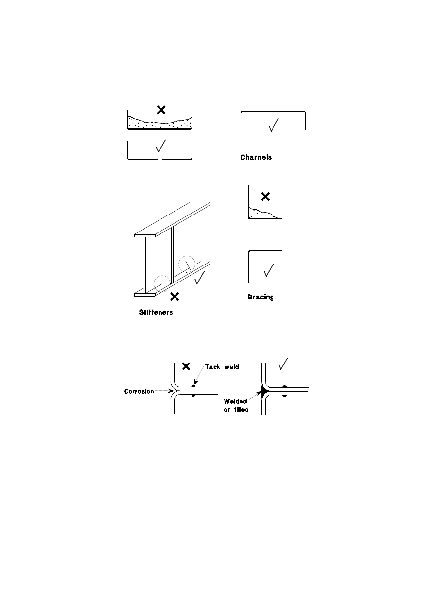
EN 1993-1-4: 2006 (E)
31
- electrical insulation;
- using paints appropriately;
- minimising periods of wetness.
f)
Reduce likelihood of attack by molten zinc in order to prevent spontaneous embrittlement.
Figure A.1: Avoiding dirt entrapment
Figure A.2: Avoiding crevices
A.6 Connections
A.6.1 General
(1)
The design of connections, in particular, needs careful attention to maintain optimum corrosion
resistance.
(2)
This is especially so for connections that might become wet from the weather, spray, immersion,
condensation, or other causes. The possibility of avoiding or reducing associated corrosion problems by
locating connections away from the source of dampness should be investigated. Alternatively, it might be
possible to remove the source of dampness; for instance, in the case of condensation, by adequate ventilation or
by ensuring that the ambient temperature within the structure lies above the dew point temperature.
Licensed copy: BSI USER 06 Document Controller, Midmac Contracting Co. W.L.L, Version correct as of 26/05/2010
14:00, (c) BSI
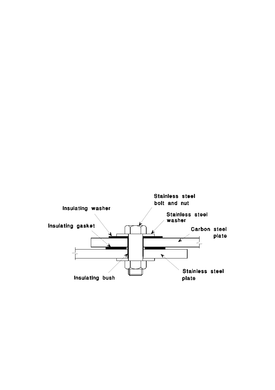
EN 1993-1-4: 2006 (E)
32
(3)
If it is not practicable to prevent a connection involving both carbon steel and stainless steel from
becoming wet, consideration should be given to preventing galvanic corrosion.
(4)
Loads and corrosion influences under service conditions should be determined and recorded as
completely and exactly as practicable.
A.6.2 Bolted connections
(1)
The use of carbon steel bolts with stainless steel structural elements should always be avoided. In bolted
connections that would be prone to an unacceptable degree of corrosion, provision should be made for
electrically isolating the carbon steel from the stainless steel elements. This generally entails the use of non-
metallic insulating washers and possibly bushes. A suitable typical detail is shown in Figure A.3. The material
forming the insulation should be sufficiently robust to prevent the carbon steel and the stainless steel from
coming into contact with each other in service.
(2)
To avoid crevice corrosion in bolted joints, care should be taken in selecting appropriate materials for the
given environment.
(3)
The bolts should be at least as resistant to corrosion in the long term under service conditions as the
connected parts.
(4)
All bolted connections should be smooth and without any gap between the connected parts.
(5)
Except in the case of connections involving carbon and stainless steels, intermediate layers that have to
transmit loads in the connection should be avoided.
(6)
Larger diameter washers should be used than for carbon steel.
Figure A.3: Avoiding galvanic corrosion when in connecting dissimilar materials
A.6.3 Welded connections
(1)
For welded connections involving carbon and stainless steels, it is generally recommended that any paint
system applied to the carbon steel should extend over the weldment, and cover some area of the stainless steel
if the connection is potentially subject to corrosion.
(2)
The properties of the parent material might be changed by welding, thereby reducing the corrosion
resistance. This is known as weld decay. The heating and cooling cycle involved in welding affects the
microstructure of all stainless steels, but some grades are affected more than others. This is of particular
Licensed copy: BSI USER 06 Document Controller, Midmac Contracting Co. W.L.L, Version correct as of 26/05/2010
14:00, (c) BSI

EN 1993-1-4: 2006 (E)
33
importance for austenitic-ferritic materials. Accordingly, it is essential that suitable welding procedures and
consumables are used and that the welding is carried out by suitably skilled welders.
(3)
Single sided partial penetration butt welds should not be used in heavily polluted environments or in
aggressive marine environments. Intermittent welds should not be used where crevice corrosion is likely to
occur.
Licensed copy: BSI USER 06 Document Controller, Midmac Contracting Co. W.L.L, Version correct as of 26/05/2010
14:00, (c) BSI
EN 1993-1-4: 2006 (E)
34
Annex B [informative] Stainless steel in the work hardened
condition
B.1 General
(1) This Annex gives rules for the use of stainless steel in the work hardened condition either by cold
rolling or by the fabrication process of the structural member, or a combination of both.
(2)
The rules are applicable only if the properties are maintained during the fabrication and execution of
the structure and during the design life of the structure. Welding or heat treatment of the products should not
be done unless it can be demonstrated by testing, in accordance with Section 7, that the execution of the
structure will not reduce the mechanical properties below the values to be adopted.
B.2 Work hardening from cold rolling
(1)
For material delivered in the cold worked conditions specified in EN
10088, increased nominal values of
yield strength f
y
and ultimate tensile strength f
u
may be adopted. The ultimate strength given in EN 10088
may be taken as the characteristic strength, see Table B.1. The yield strength in Table B.1 may be used as
characteristic strength provided that it is guaranteed by the producer.
(2)
The design rules given in this Part 1-4 are applicable for material up to grade C700 and CP350. For
higher grades, design should be by testing according to Section 7, except that the cross-section resistance
without local or global instability may be calculated according to Section 5 for cross-section classes 1, 2 and 3.
Table B.1: Nominal values of the yield strength f
y
and the ultimate tensile strength f
u
for work hardened structural stainless steels to EN 10088
Type of
stainless
steel
0.2% proof
strength level in
the cold worked
condition
f
y
N/mm
2
Tensile strength
level in the cold
worked condition
f
u
N/mm
2
CP350
350
C700
700
CP500
500
C850
850
Austenitic
steels
CP700
700
C1000
1000
B.3 Work hardening from fabrication
(1)
Work hardening during fabrication of structural components may be utilised in the design provided that
the effect of work hardening has been verified by full size tests in accordance with Section 7.
(2)
For design of connections which are not part of the full size testing, nominal strength values should be
used.
Licensed copy: BSI USER 06 Document Controller, Midmac Contracting Co. W.L.L, Version correct as of 26/05/2010
14:00, (c) BSI

EN 1993-1-4: 2006 (E)
35
Annex C [informative] Modelling of material behaviour
C.1 General
(1)
This Annex gives guidance for the modelling of material behaviour.
C.2 Material properties
(1)
Material properties E, f
y
and f
u
for FE-calculations should be taken as characteristic values. Rules for
design by FE methods are given in informative Annex C of EN 1993-1-5.
(2)
Depending on the accuracy required and the maximum strains attained, the following approaches for
modelling the material behaviour may be used:
a) stress-strain curve with strain hardening calculated as follows:
≤
<
−
−
+
−
+
+
≤
+
=
u
y
m
y
u
y
u
y
y
y
y
n
y
f
f
f
f
f
E
f
E
f
f
f
E
σ
σ
ε
σ
σ
σ
σ
ε
for
002
,
0
for
002
,
0
(C.1)
where:
n
is a coefficient defined as
)
/
ln(
)
20
ln(
01
,
0
p
y
R
f
n
=
in which R
p0,01
is the 0,01% proof stress.
n
may be taken from Table 4.1 or it may be calculated from measured properties
E
y
is the tangent modulus of the stress-strain curve at the yield strength defined as:
y
y
f
E
n
E
E
002
,
0
1
+
=
u
ε
is the ultimate strain, corresponding to the ultimate strength f
u
, where
u
ε
may be obtained from the
approximation:
u
y
u
f
f
−
=1
ε
but
A
u
≤
ε
where A is the elongation after fracture defined in EN 10088.
m
is a coefficient that may be determined as
u
y
f
f
m
5
,
3
1
+
=
b) stress-strain curve calculated as in a) above from measured properties
c) true stress-strain curve calculated from an engineering stress-strain curve as measured as follows:
)
1
ln(
)
1
(
ε
ε
ε
σ
σ
+
=
+
=
true
true
(C.2)
Licensed copy: BSI USER 06 Document Controller, Midmac Contracting Co. W.L.L, Version correct as of 26/05/2010
14:00, (c) BSI

BS EN
1993-1-4:2006
BSI
389 Chiswick High Road
London
W4 4AL
BSI — British Standards Institution
BSI is the independent national body responsible for preparing
British Standards. It presents the UK view on standards in Europe and at the
international level. It is incorporated by Royal Charter.
Revisions
British Standards are updated by amendment or revision. Users of
British Standards should make sure that they possess the latest amendments or
editions.
It is the constant aim of BSI to improve the quality of our products and services.
We would be grateful if anyone finding an inaccuracy or ambiguity while using
this British Standard would inform the Secretary of the technical committee
responsible, the identity of which can be found on the inside front cover.
Tel: +44 (0)20 8996 9000. Fax: +44 (0)20 8996 7400.
BSI offers members an individual updating service called PLUS which ensures
that subscribers automatically receive the latest editions of standards.
Buying standards
Orders for all BSI, international and foreign standards publications should be
addressed to Customer Services. Tel: +44 (0)20 8996 9001.
Fax: +44 (0)20 8996 7001. Email: orders@bsi-global.com. Standards are also
available from the BSI website at http://www.bsi-global.com.
In response to orders for international standards, it is BSI policy to supply the
BSI implementation of those that have been published as British Standards,
unless otherwise requested.
Information on standards
BSI provides a wide range of information on national, European and
international standards through its Library and its Technical Help to Exporters
Service. Various BSI electronic information services are also available which give
details on all its products and services. Contact the Information Centre.
Tel: +44 (0)20 8996 7111. Fax: +44 (0)20 8996 7048. Email: info@bsi-global.com.
Subscribing members of BSI are kept up to date with standards developments
and receive substantial discounts on the purchase price of standards. For details
of these and other benefits contact Membership Administration.
Tel: +44 (0)20 8996 7002. Fax: +44 (0)20 8996 7001.
Email: membership@bsi-global.com.
Information regarding online access to British Standards via British Standards
Online can be found at http://www.bsi-global.com/bsonline.
Further information about BSI is available on the BSI website at
http://www.bsi-global.com.
Copyright
Copyright subsists in all BSI publications. BSI also holds the copyright, in the
UK, of the publications of the international standardization bodies. Except as
permitted under the Copyright, Designs and Patents Act 1988 no extract may be
reproduced, stored in a retrieval system or transmitted in any form or by any
means – electronic, photocopying, recording or otherwise – without prior written
permission from BSI.
This does not preclude the free use, in the course of implementing the standard,
of necessary details such as symbols, and size, type or grade designations. If these
details are to be used for any other purpose than implementation then the prior
written permission of BSI must be obtained.
Details and advice can be obtained from the Copyright & Licensing Manager.
Tel: +44 (0)20 8996 7070. Fax: +44 (0)20 8996 7553.
Email: copyright@bsi-global.com.
Licensed copy: BSI USER 06 Document Controller, Midmac Contracting Co. W.L.L, Version correct as of 26/05/2010
14:00, (c) BSI
Wyszukiwarka
Podobne podstrony:
Eurocode 3 Part 3 2 2006 Design of Steel Structures Towers, Masts and Chimneys Chimneys
Eurocode 3 Part 1 3 2006 UK NA Design of steel structures General rules Supplementary rules for
Eurocode 3 Part 1 2 2005 UK NA Design of steel structures General rules Structural fire design
Eurocode 3 Part 1 7 2009 Design of Steel Structures Plated Structures Subject to Out of Plane Loa
Eurocode 3 Part 1 9 2005 Design of Steel Structures Fatigue
Eurocode 3 Part 1 5 2009 Design of Steel Structures Plated Structural Elements
Eurocode 3 Part 1 12 2007 UK NA Design of Steel Structures Additional Rules for the Extension of
Eurocode 2 Part 3 2006 Design of concrete structures Liquid retaining and containing structures
Eurocode 3 Part 1 12 2007 Design of Steel Structures Additional Rules for the Extension of EN 199
Eurocode 6 Part 1 1 1996 2005 Design of Masonry Structures General Rules for Reinforced and Unre
Eurocode 3 Part 1 11 2006 Design of Steel Structures Design of Structures With Tension Components
Eurocode 6 Part 1 2 1996 2005 Design of Masonry Structures General Rules Structural Fire Design
Eurocode 2 Part 1 1 2004 NA UK Design of concrete structures General rules and rules for buildin
Eurocode 3 Part 2 2006 UK NA Design of steel structures Steel bridges
Eurocode 5 EN 1995 1 1 Design Of Timber Structures Part 1 1 General Rules
Eurocode 5 EN 1995 1 1 Design Of Timber Structures Part 1 1 General Rules
Eurocode 6 Part 2 1996 2006 Design of Masonry Structures Design Considerations, Selection of Mat
Eurocode 3 Part 1 9 2005 UK NA Design of Steel Structures Fatigue
więcej podobnych podstron