BRITISH STANDARD
BS EN
1996-2:2006
Eurocode 6 — Design of
masonry structures —
Part 2: Design considerations, selection
of materials and execution of masonry
ICS 91.010.30; 91.080.30
12&23<,1*:,7+287%6,3(50,66,21(;&(37$63(50,77('%<&23<5,*+7/$:
Incorporating
corrigendum
September 2009
Licensed copy: BSI USER 06 Document Controller, Midmac Contracting Co. W.L.L, Version correct as of 03/08/2011 10:43, (c) BSI

National foreword
This British Standard is the UK implementation of EN 1996-2:2006,
incorporating corrigendum September 2009. It supersedes
DD ENV 1996-2:2001 which is withdrawn.
The start and finish of text introduced or altered by corrigendum is
indicated in the text by tags. Text altered by CEN corrigendum
September 2009 is indicated in the text by ˆ‰.
The structural Eurocodes are divided into packages by grouping
Eurocodes for each of the main materials, concrete, steel, composite
concrete and steel, timber, masonry and aluminium. This is to enable a
common date of withdrawal (DOW) for all the relevant parts that are
needed for a particular design. The conflicting national standards will
be withdrawn at the end of the co-existence period, after all the EN
Eurocodes of a package are available.
Following publication of the EN, there is a period allowed for national
calibration during which the National Annex is issued, followed by a
co-existence period of a maximum three years. During the co-existence
period Member States will be encouraged to adapt their national
provisions.
At the end of this co-existence period, the conflicting parts of national
standard(s) will be withdrawn.
In the UK, the corresponding national standards are:
— BS 5628-1:1992, Code of practice for use of masonry. Structural
use of unreinforced masonry
— BS 5628-2:2000, Code of practice for use of masonry. Structural
use of reinforced and prestressed masonry
— BS 5628-3:2001, Code of practice for use of masonry. Materials
and components, design and workmanship
and based on this transition period, these standards will be
withdrawn/ revised on a date to be announced, but at the latest by
March 2010.
BS EN 1996-2:2006
This British Standard was
published under the authority
of the Standards Policy and
Strategy Committee
on 15 February 2006
© BSI 2010
Amendments/corrigenda issued since publication
Date
Comments
31 March 2010
Implementation of CEN corrigendum September 2009
ISBN 978 0 580 69572 8
Licensed copy: BSI USER 06 Document Controller, Midmac Contracting Co. W.L.L, Version correct as of 03/08/2011 10:43, (c) BSI

The UK participation in its preparation was entrusted by Technical Committee
B/525, Building and civil engineering structures, to Subcommittee B/525/6, Use
of masonry.
A list of organizations represented on this subcommittee can be obtained on
request to its secretary.
Where a normative part of this EN allows for a choice to be made at the
national level, the range and possible choice will be given in the normative text,
and a note will qualify it as a Nationally Determined Parameter (NDP). NDPs
can be a specific value for a factor, a specific level or class, a particular method
or a particular application rule if several are proposed in the EN.
To enable EN 1996-2 to be used in the UK, the NDPs will be published in a
National Annex, which will be made available by BSI in due course, after public
consultation has taken place.
This publication does not purport to include all the necessary provisions of a
contract. Users are responsible for its correct application.
Compliance with a British Standard cannot confer immunity from legal
obligations.
BS EN 1996-2:2006
i
Licensed copy: BSI USER 06 Document Controller, Midmac Contracting Co. W.L.L, Version correct as of 03/08/2011 10:43, (c) BSI

blank
Licensed copy: BSI USER 06 Document Controller, Midmac Contracting Co. W.L.L, Version correct as of 03/08/2011 10:43, (c) BSI

EUROPEAN STANDARD
NORME EUROPÉENNE
EUROPÄISCHE NORM
EN 1996-2
January 2006
ICS 91.010.30; 91.080.30
Supersedes ENV 1996-2:1998
English Version
Eurocode 6 - Design of masonry structures - Part 2: Design
considerations, selection of materials and execution of masonry
Eurocode 6 - Calcul des ouvrages en maçonnerie - Partie
2: Conception, choix des matériaux et mise en oeuvre des
maçonneries
Eurocode 6 - Bemessung und Konstruktion von
Mauerwerksbauten - Teil 2: Planung, Auswahl der
Baustoffe und Ausführung von Mauerwerk
This European Standard was approved by CEN on 24 November 2005.
CEN members are bound to comply with the CEN/CENELEC Internal Regulations which stipulate the conditions for giving this European
Standard the status of a national standard without any alteration. Up-to-date lists and bibliographical references concerning such national
standards may be obtained on application to the Central Secretariat or to any CEN member.
This European Standard exists in three official versions (English, French, German). A version in any other language made by translation
under the responsibility of a CEN member into its own language and notified to the Central Secretariat has the same status as the official
versions.
CEN members are the national standards bodies of Austria, Belgium, Cyprus, Czech Republic, Denmark, Estonia, Finland, France,
Germany, Greece, Hungary, Iceland, Ireland, Italy, Latvia, Lithuania, Luxembourg, Malta, Netherlands, Norway, Poland, Portugal, Romania,
Slovakia, Slovenia, Spain, Sweden, Switzerland and United Kingdom.
EUROPEAN COMMITTEE FOR STANDARDIZATION
C O M I T É E U R O P É E N D E N O R M A L I S A T I O N
E U R O P Ä I S C H E S K O M I T E E F Ü R N O R M U N G
Management Centre: rue de Stassart, 36 B-1050 Brussels
© 2006 CEN
All rights of exploitation in any form and by any means reserved
worldwide for CEN national Members.
Ref. No. EN 1996-2:2006: E
Incorporating corrigendum September 2009
Licensed copy: BSI USER 06 Document Controller, Midmac Contracting Co. W.L.L, Version correct as of 03/08/2011 10:43, (c) BSI

EN 1996-2:2006 (E)
2
Contents
Page
Background of the Eurocode programme......................................................................................... 4
Status and field of application of Eurocodes..................................................................................... 5
National Standards implementing Eurocodes .................................................................................. 6
Links between Eurocodes and harmonised technical specifications (ENs and ETAs) for
products .................................................................................................................................... 7
Additional information specific to EN 1996-2................................................................................... 7
National annex for EN 1996-2 ............................................................................................................ 7
1
General ..................................................................................................................................... 8
1.1
Scope of Part 2 of Eurocode 6................................................................................................. 8
1.2
Normative references .............................................................................................................. 9
1.3
Assumptions ............................................................................................................................. 9
1.4
Distinction between principles and application rules........................................................... 9
1.5
Definitions............................................................................................................................... 10
1.5.1 General ................................................................................................................................... 10
1.5.2 Terms and definitions relating to communication of design ............................................. 10
1.5.3 Terms relating to climatic factors and exposure conditions.............................................. 10
1.5.4 Term relating to masonry units............................................................................................ 10
1.5.5 Other terms ............................................................................................................................ 11
1.6
Symbols................................................................................................................................... 11
2
Design Considerations........................................................................................................... 11
2.1
Factors affecting the durability of masonry........................................................................ 11
2.1.1 General ................................................................................................................................... 11
2.1.2 Classification of environmental conditions ......................................................................... 11
2.1.2.1
Micro conditions of exposure......................................................................................... 11
2.1.2.2
Climatic factors (macro conditions of exposure) ......................................................... 12
2.1.3 Aggressive chemical environments ...................................................................................... 12
2.2
Selection of materials............................................................................................................. 13
2.2.1 General ................................................................................................................................... 13
2.2.2 Masonry units ........................................................................................................................ 13
2.2.3 Masonry mortar and concrete infill..................................................................................... 14
2.2.3.1
General ............................................................................................................................ 14
2.2.3.2
Selection of factory made masonry mortar and concrete infill .................................. 14
2.2.3.3
Selection of site-made masonry mortar and concrete infill ........................................ 14
2.2.4 Ancillary components and reinforcement ........................................................................... 15
2.3
Masonry.................................................................................................................................. 15
2.3.1 Detailing.................................................................................................................................. 15
2.3.2 Joint finishes........................................................................................................................... 15
2.3.3 Masonry movement ............................................................................................................... 15
2.3.4 Movement joints .................................................................................................................... 16
BS EN 1996-2:2006
Licensed copy: BSI USER 06 Document Controller, Midmac Contracting Co. W.L.L, Version correct as of 03/08/2011 10:43, (c) BSI

EN 1996-2:2006 (E)
3
2.3.4.1
General .............................................................................................................................16
2.3.4.2
Spacing of movement joints............................................................................................17
2.3.5 Permissible deviations............................................................................................................17
2.3.6 Resistance to moisture penetration through external walls ...............................................18
3
Execution.................................................................................................................................18
3.1
General ....................................................................................................................................18
3.2
Acceptance, handling and storage of materials ...................................................................18
3.2.1 General ....................................................................................................................................18
3.2.2 Reinforcement and prestressing materials ..........................................................................18
3.3
Preparation of materials........................................................................................................19
3.3.1 Site-made mortars and concrete infill ..................................................................................19
3.3.1.1
General .............................................................................................................................19
3.3.1.2
Chloride content ..............................................................................................................19
3.3.1.3
Strength of mortar and concrete infill...........................................................................19
3.3.1.4
Admixtures and additions ..............................................................................................19
3.3.1.5
Gauging ............................................................................................................................19
3.3.1.6
Mixing method and mixing time ....................................................................................20
3.3.1.7
Workable life of mortars and concrete infill containing cement ................................20
3.3.1.8
Mixing in cold weather ...................................................................................................20
3.3.2 Factory made mortars, pre-batched mortars, pre-mixed lime sand mortars and
ready mixed concrete infill ....................................................................................................20
3.4
Permissible deviations............................................................................................................21
3.5
Execution of masonry.............................................................................................................23
3.5.1 General ....................................................................................................................................23
3.5.2 Laying masonry units.............................................................................................................23
3.5.3 Pointing and jointing for masonry other than thin layer masonry ...................................24
3.5.3.1
Pointing ............................................................................................................................24
3.5.3.2
Jointing.............................................................................................................................24
3.5.4 Incorporation of damp proof course membranes ...............................................................24
3.5.5 Movement joints .....................................................................................................................24
3.5.6 Incorporation of thermal insulation materials ....................................................................24
3.5.7 Cleaning facing masonry .......................................................................................................24
3.6
Curing and protective procedures during execution ..........................................................24
3.6.1 General ....................................................................................................................................24
3.6.2 Protection against rain...........................................................................................................25
3.6.3 Protection against freeze/thaw cycling .................................................................................25
3.6.4 Protection against effects of low humidity ...........................................................................25
3.6.5 Protection against mechanical damage ................................................................................25
3.6.6 Construction height of masonry............................................................................................25
A.1 Classification................................................................................................................................26
A.2 Exposure to wetting.....................................................................................................................27
B.1 Selection of masonry units and mortar......................................................................................29
C.1 Exposure classes ..........................................................................................................................31
C.2 Selection of materials ..................................................................................................................31
BS EN 1996-2:2006
Licensed copy: BSI USER 06 Document Controller, Midmac Contracting Co. W.L.L, Version correct as of 03/08/2011 10:43, (c) BSI

EN 1996-2:2006 (E)
4
Foreword
This document EN 1996-2 has been prepared by Technical Committee CEN/TC250 “Structural
Eurocodes”, the secretariat of which is held by BSI.
This European Standard shall be given the status of a national standard, either by publication of an
identical text or by endorsement, at the latest by July 2006, and conflicting national standards shall
be withdrawn at the latest by March 2010.
CEN/TC 250 is responsible for all Structural Eurocodes.
This document supersedes ENV 1996-2:1998
According to the CEN/CENELEC Internal Regulations, the national standards organizations of the
following countries are bound to implement this European Standard: Austria, Belgium, Cyprus,
Czech Republic, Denmark, Estonia, Finland, France, Germany, Greece, Hungary, Iceland, Ireland,
Italy, Latvia, Lithuania, Luxembourg, Malta, Netherlands, Norway, Poland, Portugal, Romania,
Slovakia, Slovenia, Spain, Sweden, Switzerland and United Kingdom.
Background of the Eurocode programme
In 1975, the Commission of the European Community decided on an action programme in the field
of construction, based on Article 95 of the Treaty. The objective of the programme was the
elimination of technical obstacles to trade and the harmonisation of technical specifications.
Within this action programme, the Commission took the initiative to establish a set of harmonised
technical rules for the design of construction works which, in a first stage, would serve as an
alternative to the national rules in force in the Member States and, ultimately, would replace them.
For fifteen years, the Commission, with the help of a Steering Committee with Representatives of
Member States, conducted the development of the Eurocodes programme, which led to the first
generation of European codes in the 1980s.
In 1989, the Commission and the Member States of the EU and EFTA decided, on the basis of an
agreement
1)
between the Commission and CEN, to transfer the preparation and the publication of the
Eurocodes to the CEN through a series of Mandates, in order to provide them with a future status of
European Standard (EN). This links de facto the Eurocodes with the provisions of all the Council’s
Directives and/or Commission’s Decisions dealing with European standards (eg. the Council
Directive 89/106/EEC on construction products - CPD - and Council Directives 93/37/EEC,
1)
Agreement between the Commission of the European Communities and the European Committee for Standardisation (CEN)
concerning the work on EUROCODES for the design of building and civil engineering works (BC/CEN/03/89).
BS EN 1996-2:2006
Licensed copy: BSI USER 06 Document Controller, Midmac Contracting Co. W.L.L, Version correct as of 03/08/2011 10:43, (c) BSI

EN 1996-2:2006 (E)
5
92/50/EEC and 89/440/EEC on public works and services and equivalent EFTA Directives initiated
in pursuit of setting up the internal market).
The Structural Eurocode programme comprises the following standards generally consisting of a
number of parts:
EN 1990, Eurocode: Basis of structural design
EN 1991, Eurocode 1: Actions on structures.
EN 1992, Eurocode 2: Design of concrete structures.
EN 1993, Eurocode 3: Design of steel structures.
EN 1994, Eurocode 4: Design of composite steel and concrete structures.
EN 1995, Eurocode 5: Design of timber structures.
EN 1996, Eurocode 6: Design of masonry structures.
EN 1997, Eurocode 7: Geotechnical design.
EN 1998, Eurocode 8: Design of structures for earthquake resistance.
EN 1999, Eurocode 9: Design of aluminium structures.
Eurocode standards recognise the responsibility of regulatory authorities in each Member State and
have safeguarded their right to determine values related to regulatory safety matters at national level
where these continue to vary from State to State.
Status and field of application of Eurocodes
The Member States of the EU and EFTA recognise that Eurocodes serve as reference documents for
the following purposes:
as a means to prove compliance of building and civil engineering works with the essential
requirements of Council Directive 89/106/EEC, particularly Essential Requirement N°1
Mechanical resistance and stability
and Essential Requirement N°2 Safety in case of fire;
as a basis for specifying contracts for construction works and related engineering services;
as a framework for drawing up harmonised technical specifications for construction products
(ENs and ETAs).
The Eurocodes, as far as they concern the construction works themselves, have a direct relationship
with the Interpretative Documents
2)
referred to in Article 12 of the CPD, although they are of a
2)
According to Article 3.3 of the CPD, the essential requirements (ERs) shall be given concrete form in interpretative documents for
the creation of the necessary links between the essential requirements and the mandates for harmonised ENs and ETAGs/ETAs.
BS EN 1996-2:2006
Licensed copy: BSI USER 06 Document Controller, Midmac Contracting Co. W.L.L, Version correct as of 03/08/2011 10:43, (c) BSI

EN 1996-2:2006 (E)
6
different nature from harmonised product standards
3)
. Therefore, technical aspects arising from the
Eurocodes work need to be adequately considered by CEN Technical Committees and/or EOTA
Working Groups working on product standards with a view to achieving full compatibility of these
technical specifications with the Eurocodes.
The Eurocode standards provide common structural design rules for everyday use for the design of
whole structures and component products of both a traditional and an innovative nature. Unusual
forms of construction or design conditions are not specifically covered and additional expert
consideration will be required by the designer in such cases.
National Standards implementing Eurocodes
The National Standards implementing Eurocodes will comprise the full text of the
Eurocode (including any annexes), as published by CEN, which may be preceded by a National title
page and National foreword, and may be followed by a National Annex (informative).
The National Annex may only contain information on those parameters which are left open in the
Eurocode for national choice, known as Nationally Determined Parameters, to be used for the design
of buildings and civil engineering works to be constructed in the country concerned, ie.:
values and/or classes where alternatives are given in the Eurocode,
values to be used where a symbol only is given in the Eurocode,
country specific data (geographical, climatic etc), eg. snow map,
the procedure to be used where alternative procedures are given in the Eurocode
and it may also contain:
decisions on the application of informative annexes,
references to non-contradictory complementary information to assist the user to apply the
Eurocode.
3)
According to Article 12 of the CPD the interpretative documents shall:
a) give concrete form to the essential requirements by harmonising the terminology and the technical bases and indicating classes or
levels for each requirement where necessary;
b) indicate methods of correlating these classes or levels of requirement with the technical specifications, e. g. methods of calculation
and of proof, technical rules for project design, etc.;
c) serve as a reference for the establishment of harmonised standards and guidelines for European technical approvals.
The Eurocodes, de facto, play a similar role in the field of ER 1 and a part of ER 2.
BS EN 1996-2:2006
Licensed copy: BSI USER 06 Document Controller, Midmac Contracting Co. W.L.L, Version correct as of 03/08/2011 10:43, (c) BSI

EN 1996-2:2006 (E)
7
Links between Eurocodes and harmonised technical specifications (ENs and
ETAs) for products
There is a need for consistency between the harmonised technical specifications for construction
products and the technical rules for works
4)
Furthermore, all the information accompanying the CE
Marking of the construction products which refer to Eurocodes shall clearly mention which
Nationally Determined Parameters have been taken into account.
This European Standard is part of EN 1996 which comprises the following Parts:
Part 1-1: General - Rules for reinforced and unreinforced masonry
Part 1-2: General rules - Structural fire design.
Part 2: Design considerations, selection of materials and execution of masonry.
Part 3: Simplified calculation methods for unreinforced masonry structures
EN 1996-2 describes the principles and requirements for design considerations, selection of materials
and execution of masonry structures.
For the design of new structures, EN 1996-1-1 is intended to be used, for direct application, together
with ENs 1990, 1991, 1992, 1993, 1994, 1995, 1997, 1998 and 1999.
EN 1996-2 is intended to be used together with EN 1990, EN 1991-1-2, EN 1996-1-1, EN 1996-1-2
and EN 1996-3.
Additional information specific to EN 1996-2
The scope of Eurocode 6 is defined in EN 1996-1-1, and this includes information on the other parts
of Eurocode 6.
National Annex for EN 1996-2
This standard gives alternative procedures, values and recommendations for classes with notes
indicating where national choices may have to be made. Therefore the National Standard
implementing EN 1996-2 should have a National Annex containing all Nationally Determined
Parameters to be used for the design of buildings and civil engineering works to be constructed in the
relevant country.
National choice is allowed in EN 1996-2 through clauses:
2.3.4.2(2)
3.5.3.1(1)
4)
see Article 3.3 and Article 12 of the CPD, as well as clauses 4.2, 4.3.1, 4.3.2 and 5.2 of ID 1.
BS EN 1996-2:2006
Licensed copy: BSI USER 06 Document Controller, Midmac Contracting Co. W.L.L, Version correct as of 03/08/2011 10:43, (c) BSI

EN 1996-2:2006 (E)
8
In addition to general references to non-contradictory complementary information specific references
may be made through clauses:
1.1(2)P
2.3.1(1)
3.4(3)
1 General
1.1 Scope of Part 2 of Eurocode 6
(1)P The scope of Eurocode 6 for Masonry Structures as given in 1.1.1 of EN 1996-1-1:2005 applies
also to this EN 1996-2.
(2)P EN 1996-2 gives basic rules for the selection of materials and execution of masonry to enable it
to comply with the design assumptions of the other parts of Eurocode 6. With the exception of the
items given in 1.1(3)P, the scope of Part 2 deals with ordinary aspects of masonry design and
execution including:
the selection of masonry materials;
factors affecting the performance and durability of masonry;
resistance of buildings to moisture penetration;
storage, preparation and use of materials on site;
the execution of masonry;
masonry protection during execution;
NOTE 1. Where general guidance only is given, additional guidance based on local conditions and practice may be made
available in non contradictory complementary documents which may be referred to in the National Annex.
NOTE 2. The scope of Eurocode 6 excludes seismic, thermal and acoustic functional performance of masonry structures;
(3)P EN 1996-2 does not cover the following items:
those aspects of masonry covered in other parts of Eurocode 6;
aesthetic aspects;
applied finishes;
health and safety of persons engaged in the design or execution of masonry;
the environmental effects of masonry buildings, civil engineering works and structures on their
surroundings.
ˆ
‰
BS EN 1996-2:2006
Licensed copy: BSI USER 06 Document Controller, Midmac Contracting Co. W.L.L, Version correct as of 03/08/2011 10:43, (c) BSI

EN 1996-2:2006 (E)
9
1.2 Normative references
(1)P This European Standard incorporates, by dated or undated reference, provisions from other
publications. These normative references are cited at the appropriate places in the text and the
publications are listed hereafter. For dated references, subsequent amendments to or revisions of any
of these publications apply to this European Standard only when incorporated in it by amendment or
revision. For undated references the latest edition of the publication applies (including amendments).
EN 206-1, Concrete -Part 1: Specification, performance, production and conformity
EN 771 (all parts), Specification for masonry units
EN 998-2, Specification for mortar for masonry – Part 2: Masonry mortar
EN 845 (all parts), Specification for ancillary components for masonry
EN 1015-11, Methods of test for mortar for masonry - Part 11: Determination of flexural and
compressive strength of hardened mortar
EN 1015-17, Methods of test for mortar for masonry – Part 17: Determination of water-soluble
chloride content of fresh mortars
EN 1052 (all parts), Methods of test for masonry
EN 1990, Eurocode: Basis of structural design
EN 1996-1-1, Eurocode 6: Design of masonry structures - Part 1: General rules for reinforced
and unreinforced masonry structures
EN 13914-1, The design, preparation and application of external rendering and internal
plastering - Part 1: External rendering
1.3 Assumptions
(1)P In addition to the assumptions given in 1.3 of EN 1990:2002 the following assumptions apply in
this EN 1996-2:
Design shall be in accordance with Section 2 taking into account Section 3.
Execution shall be in accordance with Section 3 taking into account Section 2.
(2) The design Principles are valid only when the Principles for execution in Section 3 are complied
with.
1.4 Distinction between Principles and Application Rules
(1)P The rules in 1.4 of EN 1990:2002 apply to this EN 1996-2.
BS EN 1996-2:2006
Licensed copy: BSI USER 06 Document Controller, Midmac Contracting Co. W.L.L, Version correct as of 03/08/2011 10:43, (c) BSI

EN 1996-2:2006 (E)
10
1.5 Definitions
1.5.1 General
(1) The terms and definitions given in 1.5 of EN 1990:2002 apply to this EN 1996-2.
(2) The terms and definitions used in EN 1996-1-1 apply to this EN 1996-2.
(3) Additional terms and definitions used in this EN 1996-2 are given the meanings contained in
1.5.2 to 1.5.5, inclusive.
1.5.2 Terms and definitions relating to communication of design
1.5.2.1
design specification
documents describing the designer's requirements for the construction, including drawings,
schedules, test reports, references to parts of other documents and written instructions
1.5.3 Terms relating to climatic factors and exposure conditions
1.5.3.1
macro conditions
climatic factors depending on the general climate of the region in which a structure is built, modified
by the effects of local topography and/or other aspects of the site
1.5.3.2
micro conditions
localised climatic and environmental factors depending on the position of a masonry element within
the overall structure and taking into account the effect of protection, or lack of protection, by
constructional details or finishes
1.5.4 Term relating to masonry units
1.5.4.1
accessory masonry unit
a masonry unit which is shaped to provide a particular function, e.g. to complete the geometry of the
masonry
BS EN 1996-2:2006
Licensed copy: BSI USER 06 Document Controller, Midmac Contracting Co. W.L.L, Version correct as of 03/08/2011 10:43, (c) BSI

EN 1996-2:2006 (E)
11
1.5.5 Other terms
1.5.5.1
applied finish
a covering of material bonded to the surface of the masonry
1.5.5.2
cavity width
the distance perpendicular to the plane of the wall between the cavity faces of the masonry leaves of
a cavity wall or that between the cavity face of a veneer wall and the masonry backing structure
1.5.5.3
cladding
a covering of material(s) fastened or anchored in front of the masonry and not in general bonded to it
1.6 Symbols
(1)P For the purpose of this standard the symbols in accordance with 1.6 of EN 1996-1-1:2005 apply.
(2)P Other symbols used in this EN 1996-2 are:
d
p
minimum depth for pointing
l
m
maximum horizontal distance between vertical movement joints in external non-loadbearing
walls;
2 Design considerations
2.1 Factors affecting the durability of masonry
2.1.1 General
(1)P Masonry shall be designed to have the performance required for its intended use.
2.1.2 Classification of environmental conditions
2.1.2.1 Micro conditions of exposure
(1)P The micro conditions to which the masonry is expected to be exposed shall be taken into
account in the design.
(2) When deciding the micro conditions of exposure of the masonry, the effect of applied finishes,
protective claddings and details should be taken into account.
BS EN 1996-2:2006
Licensed copy: BSI USER 06 Document Controller, Midmac Contracting Co. W.L.L, Version correct as of 03/08/2011 10:43, (c) BSI

EN 1996-2:2006 (E)
12
(3) Micro conditions of exposure of completed masonry should be categorised into classes, as
follows:
MX1 - In a dry environment;
MX2 - Exposed to moisture or wetting;
MX3 - Exposed to moisture or wetting plus freeze/thaw cycling;
MX4 - Exposed to saturated salt air or seawater;
MX5 - In an aggressive chemical environment.
NOTE When necessary, more closely defined conditions within these classes may be specified using the sub-classes in
Annex A (e.g. MX2.1 or MX2.2 and M X 3.1 or M X 3.2).
(4) To produce masonry that meets specified performance criteria and withstands the environmental
conditions to which it is exposed, the determination of the exposure class should take into account:
climatic factors;
severity of exposure to moisture or wetting;
exposure to freeze/thaw cycling;
presence of chemical materials that may lead to damaging reactions.
2.1.2.2 Climatic factors (macro conditions of exposure)
(1)P The effect of the macro conditions on the micro conditions shall be taken into account when
determining the wetting of masonry and its exposure to freeze/thaw cycling.
(2) Concerning the macro conditions the following should be taken into account:
─ rain and snow;
─ the combination of wind and rain;
─ temperature variation;
─ relative humidity variation.
NOTE It is acknowledged that climates (macro conditions) vary considerably throughout Europe and that certain aspects
of climate can influence the risk of exposure of masonry to wetting and/or freeze/thaw cycling. However, it is the
classification of the micro conditions that is relevant for determining the durability of masonry rather than the ranking of
the macro conditions. Examples of relative exposure to wetting of masonry elements in a typical building are shown in
Annex A.
2.1.3 Aggressive chemical environments
(1) In coastal areas the exposure of masonry to airborne chlorides or seawater should be taken into
account.
BS EN 1996-2:2006
Licensed copy: BSI USER 06 Document Controller, Midmac Contracting Co. W.L.L, Version correct as of 03/08/2011 10:43, (c) BSI

EN 1996-2:2006 (E)
13
(2) Possible sources of sulfates include the following:
natural soils;
groundwater;
waste deposits and filled ground;
construction materials;
airborne pollutants.
(3) Where the presence of aggressive chemicals in the environment, other than airborne chlorides or
seawater, can affect masonry, class MX5 should be assumed. Where salts can be transported by
water moving through the masonry, the potential for increased concentrations and quantities of
available chemicals should be taken into account.
2.2 Selection of materials
2.2.1 General
(1)P Materials, where incorporated in the works, shall be able to resist the actions to which they are
expected to be exposed, including environmental actions.
(2)P Only materials, products, and systems with established suitability shall be used.
(3) Where the selection of materials for masonry is not otherwise covered in Part 2, it should be done
in accordance with local practice and experience.
NOTE 1 Established suitability may result from conformity to a European Standard that is either referred to by this
standard or that specifically refers to uses within the scope of this standard. Alternatively, where either there is no
appropriate European Standard, or the material or product deviates from the requirements of an appropriate European
Standard, established suitability may result from conformity to either:
-
a Technical Approval, or
-
a national standard, or
-
other provisions,
any of which refer specifically to uses within the scope of this standard and are accepted in the place of use of the
material or product.
NOTE 2 Acceptable masonry unit specifications and mortar may be selected from Annex B, Table B.1 and B.2, in
relation to durability.
2.2.2 Masonry units
(1) The requirements for masonry units should be specified in accordance with the following parts of
EN 771 relating to the type of material:
EN 771-1 for clay masonry units;
EN 771-2 for calcium silicate masonry units;
EN 771-3 for aggregate concrete masonry units;
BS EN 1996-2:2006
Licensed copy: BSI USER 06 Document Controller, Midmac Contracting Co. W.L.L, Version correct as of 03/08/2011 10:43, (c) BSI

EN 1996-2:2006 (E)
14
EN 771-4 for autoclaved aerated concrete masonry units;
EN 771-5 for manufactured stone masonry units;
EN 771-6 for natural stone masonry units.
(2) For products not in accordance with EN 771 (e.g. reclaimed products) the design specification
should state the required product performance characteristics and the means of their verification
including the requirements for sampling and frequency of testing.
2.2.3 Masonry mortar and concrete infill
2.2.3.1 General
(1) Masonry mortar should be selected according to the exposure condition of the masonry and the
specification of the masonry units. Until a European Standard method of test for durability is
available, the suitability of masonry mortars should be determined on the basis of established local
experience of the performance of the particular materials and mix proportions.
2.2.3.2 Selection of factory made masonry mortar and concrete infill
(1) When factory made masonry mortar or concrete infill is considered for use in exposure classes
MX4 or MX5 the manufacturer's advice should be sought as to its suitability.
NOTE Until a European Standard method of test for durability is available, the suitability of masonry mortars
conforming to EN 998-2 is based on the manufacturer's experience appropriate to the intended use.
2.2.3.3 Selection of site-made masonry mortar and concrete infill
(1) For site-made masonry mortar and concrete infill the design specification should state the
required product performance characteristics and the means of their verification including the
requirements for sampling and frequency of testing. In addition, where the designer is satisfied that a
prescriptive specification will provide the required performance, a detailed specification of the
constituent materials, their proportions and the method of mixing may be given either on the basis of
tests carried out on trial mixes and/or on the basis of authoritative publicly available references
acceptable in the place of use.
(2) The guidance in 3.3.1 should be taken into account particularly where admixtures, additions and
pigments are to be used.
(3) In exposure classes MX1, MX2 or MX3, the masonry mortar should be specified for durability
using the terms defined in EN 998-2:
masonry subjected to passive exposure;
masonry subjected to moderate exposure;
masonry subjected to severe exposure.
NOTE 2.2.3.3(1) requires performance characteristics to be specified in all cases. For durability, 2.2.3.3(3) requires it to
be done by reference to the stated terminology. It is then an option for the designer to give a prescriptive specification
BS EN 1996-2:2006
Licensed copy: BSI USER 06 Document Controller, Midmac Contracting Co. W.L.L, Version correct as of 03/08/2011 10:43, (c) BSI

EN 1996-2:2006 (E)
15
that will fulfil the performance requirements, or alternatively, it can be done as an execution task in accordance with
3.3.1.1(2). For general applications mortar durability designations may be selected from table B.2.
(4) When site-made masonry mortar or concrete infill is to be specified for use in exposure classes
MX4 or MX5, the mix proportions to provide adequate durability for the particular conditions should
be selected on the basis of authoritative publicly available references acceptable in the place of use.
(5) Where adhesion between masonry units and mortar (bond strength) is a particular design
requirement, the mix proportions should take this into account.
NOTE The manufacturer of masonry units may give advice on the type of masonry mortar to be used or tests may be
carried out in accordance with relevant parts of EN 1052.
2.2.4 Ancillary components and reinforcement
(1)P Ancillary components and their fixings shall be corrosion resistant in the environment in which
they are used.
NOTE 1 Annex C gives guidance on materials and corrosion protection systems for ancillary components in relation to
exposure classes.
NOTE 2 Reinforcing steel should be selected following the recommendations given in 4.3.3 of EN 1996-1-1:2005
2.3 Masonry
2.3.1 Detailing
(1) Where the detailing of masonry is not otherwise covered in this EN 1996-2, it should be done in
accordance with local practice and experience.
NOTE The local practice and experience may be given in non-contradictory complementary information and referenced
in the National Annex
2.3.2 Joint finishes
(1) Pointing mortar should be compatible with the jointing mortar.
2.3.3 Masonry movement
(1)P The possibility of masonry movement shall be allowed for in the design such that the
performance of the masonry in use is not adversely affected by such movement.
(2) Where intersecting walls do not all have effectively similar deformation behaviour, the
connection between such walls should be able to accommodate any resulting differential movement.
(3) Movement tolerant ties should be provided where required to accommodate relative in-plane
movements between masonry leaves or between masonry and other structures to which the masonry
is attached.
(4) Where cavity wall ties that are not movement tolerant are used, the uninterrupted height between
horizontal movement joints in the outer leaf of external cavity walls should be limited to avoid the
loosening of the wall ties.
BS EN 1996-2:2006
Licensed copy: BSI USER 06 Document Controller, Midmac Contracting Co. W.L.L, Version correct as of 03/08/2011 10:43, (c) BSI

EN 1996-2:2006 (E)
16
(5) Movement joints should be used, or reinforcement should be incorporated into the masonry, in
order to minimise cracking, bowing or distortion caused by expansion, shrinkage, differential
movements or creep.
2.3.4 Movement joints
2.3.4.1 General
(1) Vertical and horizontal movement joints should be provided to allow for the effects of thermal
and moisture movement, creep and deflection and the possible effects of internal stresses caused by
vertical or lateral loading, so that the masonry does not suffer damage.
(2) The position of movement joints should take into account the need to maintain structural integrity
of the wall.
(3) Movement joints should be designed and positioned having regard to:
the type of masonry unit material taking into account the moisture movement characteristics of
the units;
the geometry of the structure taking into account openings and the proportions of panels;
the degree of restraint;
the response of the masonry to long and short term loading;
the response of the masonry to thermal and climatic conditions;
fire resistance;
sound and thermal insulation requirements;
the presence or not of reinforcement.
(4) The detailing of a movement joint should enable the movement joint to accommodate the
anticipated movements, both reversible and irreversible, without damage to the masonry.
(5) All movement joints should pass through the full thickness of the wall or the outer leaf of a cavity
wall and through any finishes that are insufficiently flexible to be able to accommodate the
movement.
(6) Slip planes should be designed to allow parts of the construction to slide, one in relation to the
other, to reduce tensile and shear stresses in the adjacent elements.
(7) In external walls, movement joints should be designed to allow any water to flow off without
causing harm to the masonry or penetrating into the building.
BS EN 1996-2:2006
Licensed copy: BSI USER 06 Document Controller, Midmac Contracting Co. W.L.L, Version correct as of 03/08/2011 10:43, (c) BSI

EN 1996-2:2006 (E)
17
2.3.4.2 Spacing of movement joints
(1) The horizontal spacing of vertical movement joints in masonry walls should take into account the
type of wall, masonry units, mortar and the specific construction details.
(2) The horizontal distance between vertical movement joints in external non-loadbearing
unreinforced masonry walls should not exceed l
m
.
NOTE 1 The value for l
m
to be used in a Country may be found in its National Annex. Recommended values for l
m
for
unreinforced non-loadbearing walls are given in the table:
Maximum recommended horizontal distance, l
m,
, between vertical movement joints
for unreinforced, non-loadbearing walls
Type of masonry
l
m
( m )
Clay masonry
12
Calcium silicate masonry
8
Aggregate concrete and manufactured stone masonry
6
Autoclaved aerated concrete masonry
6
Natural stone masonry
12
NOTE 2 The maximum horizontal spacing of vertical movement joints may be increased for walls containing bed joint
reinforcement conforming to EN 845-3. Guidance may be obtained from the manufacturers of bed joint reinforcement
(3) The distance of the first vertical joint from a restrained vertical edge of a wall should not exceed
half the value of l
m
.
(4) The need for vertical movement joints in unreinforced loadbearing walls should be considered.
NOTE No recommended values for the spacing are given as they depend on local building traditions, type of floors used
and other construction details.
(5) The positioning of movement joints should take into account the need to maintain structural
integrity of load bearing internal walls.
(6) Where horizontal joints are required to accommodate vertical movement in an unreinforced
veneer wall or in an unreinforced non-loadbearing outer leaf of a cavity wall, the spacing of
horizontal movement joints should take into account the type and positioning of the support system.
2.3.5 Permissible deviations
(1) Permissible deviations of the constructed masonry from its intended position should be specified.
(2) The permissible deviations should be specifically stated as values in the design specification or in
accordance with locally accepted standards.
NOTE Compliance with tolerances is necessary in order to ensure that, despite the inevitable inaccuracies at each stage in
the building process, the functional requirements are satisfied and the correct assembly of structures and components
takes place without the need for adjustment or reworking. The permissible tolerances for dimensions of masonry units are
specified in EN 771.
(3) Unless otherwise allowed for in the structural design, the permissible deviations should not be
greater than the values given in Table 3.1. Where the design allows for deviations in excess of the
BS EN 1996-2:2006
Licensed copy: BSI USER 06 Document Controller, Midmac Contracting Co. W.L.L, Version correct as of 03/08/2011 10:43, (c) BSI

EN 1996-2:2006 (E)
18
values in Table 3.1, the permissible deviations should be specifically stated in the design
specification.
NOTE Table 3.1 gives the maximum deviations that have been taken into account in EN 1996-1-1
2.3.6 Resistance to moisture penetration through external walls
(1) Where there is a need for greater resistance to moisture penetration than can be provided by the
masonry alone, the application of a suitable rendering, ventilated cladding or other suitable surface
treatment should be used.
NOTE Guidance on the use of external renderings is given in EN 13914-1, The design, preparation and application of
external renderings. Where a total barrier to rain penetration is required, a ventilated waterproof cladding system may be
applied to the masonry.
3 Execution
3.1 General
(1)P All materials used and all work constructed shall be in accordance with the design specification.
(2)P Precautions shall be taken to ensure the overall stability of the structure or of individual walls
during construction.
3.2 Acceptance, handling and storage of materials
3.2.1 General
(1)P The handling and storage of materials and masonry products for use in masonry shall be such
that the materials are not damaged so as to become unsuitable for their purpose.
(2) Where required by the design specification, materials should be sampled and tested.
(3) Different materials should be stored separately.
3.2.2 Reinforcement and prestressing materials
(1)P The surface condition of reinforcement and prestressing materials shall be examined prior to use
and it shall be free from deleterious substances, which may affect adversely the steel, concrete or
mortar or the bond between them.
(2) Damage or deformation of reinforcement should be avoided during storage and handling. Steel
reinforcing bars, steel prestressing bars and/or tendons and prefabricated bed joint reinforcement
should be clearly identified, and stored off the ground, well away from mud, oil, grease, paint or
welding operations.
(3) During storage and handling of prestressing steel, welding in the vicinity of tendons without the
provision of special protection (from welding splatter) should be prevented.
(4) For sheaths, the following should be taken into account:
BS EN 1996-2:2006
Licensed copy: BSI USER 06 Document Controller, Midmac Contracting Co. W.L.L, Version correct as of 03/08/2011 10:43, (c) BSI

EN 1996-2:2006 (E)
19
local damage and corrosion inside should be avoided;
water-tightness should be ensured.
3.3 Preparation of materials
3.3.1 Site-made mortars and concrete infill
3.3.1.1 General
(1) Site-made mortars and concrete infill should be produced using a mix prescription that will result
in the required performance characteristics. When the mix prescription is not given in the design
specification, the detailed specification of constituent materials, their proportions and the method of
mixing should be selected on the basis of tests carried out on trial mixes and/or on the basis of
authoritative publicly available references acceptable in the place of use.
(2) When tests are required they should be carried out in accordance with the design specification.
When test results indicate that the mix prescription is not giving the required performance
characteristics, the mix prescription should be amended and if it is part of the design specification
any amendments should be agreed with the designer.
3.3.1.2 Chloride content
(1) When sampled in accordance with EN 998-2, and tested in accordance with EN 1015-17 or when
using a calculation method based on measured chlorine ion content of the constituents of the mortar,
the maximum value permitted in EN 998-2 should not be exceeded.
3.3.1.3 Strength of mortar and concrete infill
(1) When the properties of mortar need to be verified, specimens should be prepared and tested in
accordance with EN 1015-11.
(2) When the properties of concrete infill need to be verified, specimens should be prepared and
tested in accordance with EN 206 -1.
3.3.1.4 Admixtures and additions
(1)P Unless permitted by the design specification, admixtures, additions or pigments shall not be
used.
3.3.1.5 Gauging
(1)P Materials for mortar and concrete infill shall be measured by weight or by volume into the
specified proportions in clean suitable measuring devices.
(2) In the proportioning of the materials for concrete infill, account should be taken of the amount of
water that will be absorbed by the masonry units and mortar joints.
BS EN 1996-2:2006
Licensed copy: BSI USER 06 Document Controller, Midmac Contracting Co. W.L.L, Version correct as of 03/08/2011 10:43, (c) BSI

EN 1996-2:2006 (E)
20
3.3.1.6 Mixing method and mixing time
(1) The mixing method and the time of mixing should ensure consistent production of the correct
mix proportions. Mortar should not be contaminated during subsequent handling.
(2) Unless hand mixing is permitted by the design specification, a suitable mechanical mixer should
be used.
(3) The mixing time should be counted from the time when all constituent materials have been added
to the mixer. Wide variation in the mixing time of different batches should be avoided.
NOTE In general, a machine mixing time of 3 minutes to 5 minutes after all the constituents have been added is suitable
and, except in the case of retarded mortars, the mixing time should not exceed 15 minutes. Prolonged mixing where air-
entraining agents are used can lead to excessive air entrainment and thus to a reduction in adhesion and durability.
(4) The mortar or concrete infill should be mixed so as to have sufficient workability for it to fill the
spaces into which it is placed, without segregation, when it is compacted.
3.3.1.7 Workable life of mortars and concrete infill containing cement
(1) Mortars and concrete infill containing cement should be ready for use when they are discharged
from the mixer, and no subsequent additions of binders, aggregates, admixtures, or water should be
made.
NOTE Water may be added to site-made mortars to replace water lost by evaporation.
(2) Mortar and concrete infill should be used before its workable life has expired. Any mortar or
concrete infill left after the initial set has commenced should be discarded and should not be
reconstituted.
3.3.1.8 Mixing in cold weather
(1)P Water, sand or premixed lime:sand mortars containing ice particles shall not be used.
(2) Unless specifically permitted by the design specification, de-icing salts or other antifreezing
agents should not be used.
3.3.2 Factory made mortars, pre-batched mortars, pre-mixed lime sand mortars and ready
mixed concrete infill
(1)P Factory made mortars and pre-batched mortars shall be used in accordance with the
manufacturer's instructions, including mixing time and type of mixer.
(2) Mortar should be mixed effectively so that a uniform distribution of the constituents is ensured.
(3) The site mixing equipment, procedures, including mixing in cold weather and care of mixing
plant and mixing time specified by the manufacturer, should be used.
(4) Pre-mixed lime:sand mortars should be mixed with the binder according to
3.3.1
.
(5)P Ready-to-use factory made mortars shall be used before the expiry of the workable life stated by
the manufacturer.
ˆ
‰
BS EN 1996-2:2006
Licensed copy: BSI USER 06 Document Controller, Midmac Contracting Co. W.L.L, Version correct as of 03/08/2011 10:43, (c) BSI

EN 1996-2:2006 (E)
21
(6) Ready mixed concrete infill should be used according to the design specification.
3.4 Permissible deviations
(1)P All work shall be constructed in accordance with the specified details within permissible
deviations.
(2) Dimensions and planeness should be checked as the work proceeds.
(3) Deviations of the constructed masonry from its intended position should not exceed the values
given in the design specification. Where values are not given in the design specification for any of
the deviations listed in Table 3.1, flatness tolerances or angular tolerances then the corresponding
permissible deviations should be the lesser of:
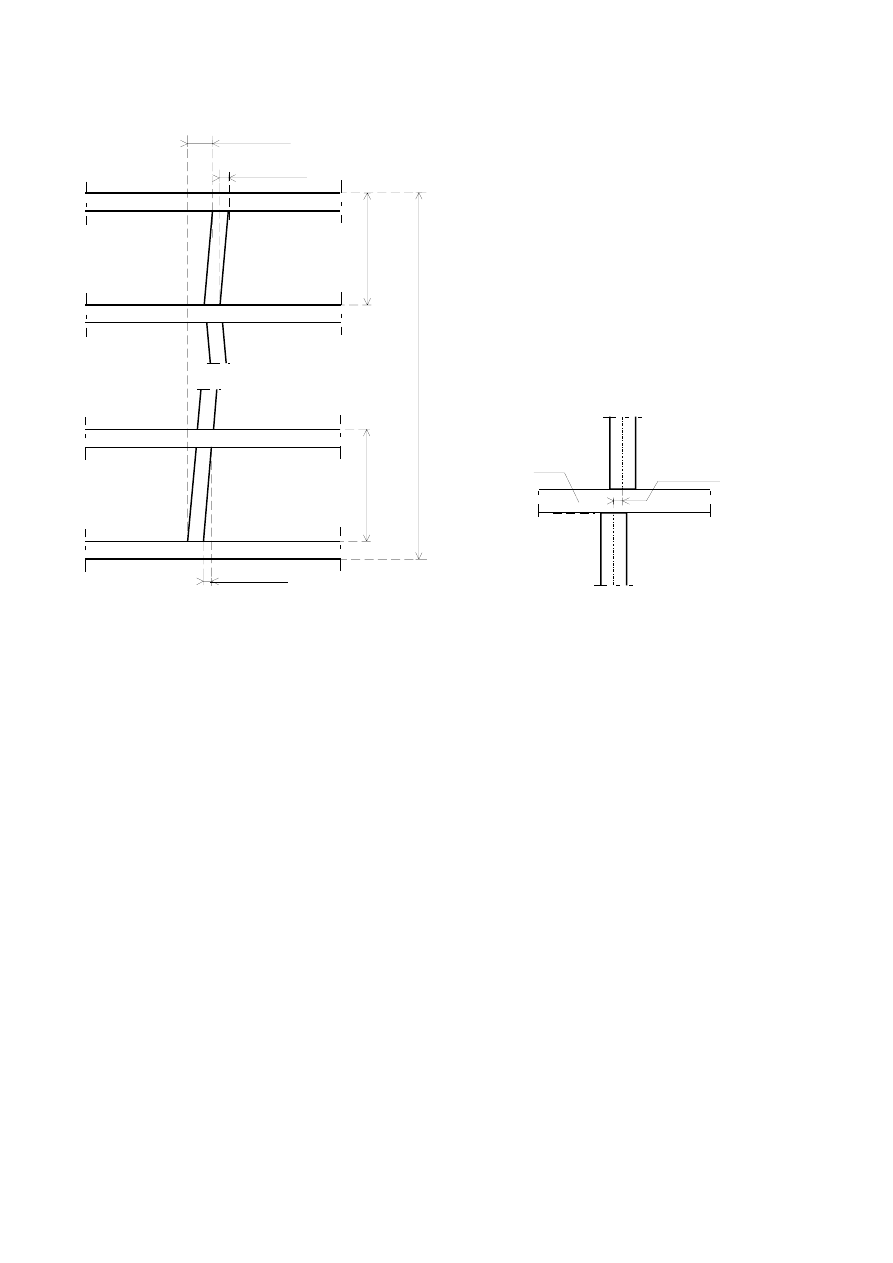
the values given in Table 3.1, see also Figure 3.1;
the values in accordance with locally accepted practice.
NOTE Such locally accepted practice can be given in non-contradictory complementary information and referenced in
the National Annex.
BS EN 1996-2:2006
Licensed copy: BSI USER 06 Document Controller, Midmac Contracting Co. W.L.L, Version correct as of 03/08/2011 10:43, (c) BSI
EN 1996-2:2006 (E)
22
1)
1)
2)
≤ 20 mm
≤ 50 mm
≤ 20 mm
≤ 20 mm
1)
Key
1) storey height
2) building height
a) Verticality
Key
1) intermediate floor
b) Vertical alignment
Figure 3.1 ─ Maximum vertical deviations
BS EN 1996-2:2006
Licensed copy: BSI USER 06 Document Controller, Midmac Contracting Co. W.L.L, Version correct as of 03/08/2011 10:43, (c) BSI
EN 1996-2:2006 (E)
23
Table 3.1 ─ Permissible deviations for masonry elements
Position
Maximum deviation
Verticality
in any one storey
± 20 mm
in total height of building of three storeys or more
± 50 mm
vertical alignment
± 20 mm
Straightness
a
in any one metre
± 10 mm
in 10 metres
± 50 mm
Thickness
of wall leaf
b
± 5 mm or ± 5 % of the leaf thickness
whichever is the greater
of overall cavity wall
± 10 mm.
a
Deviation from straightness is measured from a straight reference line between any two points.
b
Excluding leaves of single masonry unit width or length, where the dimensional tolerances of the
masonry units govern the leaf thickness.
(4) Unless otherwise specified, the first course of masonry should not overhang the edge of a floor or
foundation by more than 15 mm.
3.5 Execution of masonry
3.5.1 Adhesion
(1) Satisfactory adhesion should be achieved by proper preparation of the masonry units and mortar.
The necessity for wetting masonry units before use should be obtained from the design specification.
Where there are no requirements in the design specification, the recommendations from the
manufacturer of the units and, where appropriate, from the manufacturer of factory made mortar,
should be followed.
(2) Unless otherwise specified, joints should not be recessed to a depth more than 5 mm in walls of
thickness 200 mm or less.
(3) When using perforated masonry units, the mortar joints should not be recessed more than 1/3 of
the shell thickness unless otherwise specified.
3.5.2 Laying masonry units
(1) Unless otherwise stated in the design specification, masonry units with frogs should be laid so
that they are fully filled with mortar.
BS EN 1996-2:2006
Licensed copy: BSI USER 06 Document Controller, Midmac Contracting Co. W.L.L, Version correct as of 03/08/2011 10:43, (c) BSI

EN 1996-2:2006 (E)
24
3.5.3 Pointing and jointing for masonry other than thin layer masonry
3.5.3.1 Pointing
(1) Where joints are to be pointed, the unhardened mortar joints should be raked out so as to have
clean sides to a depth of at least d
p
, but no more than 15% of the wall thickness, measured from the
finished surface of the joint. Loose material should be brushed out.
NOTE The value for d
p
to be used in a Country may be found in its National Annex. The recommended value for d
p
is
15 mm for a wall thickness of 100 mm.
(2) Before pointing the whole area should be cleaned and if necessary wetted to give the best
practicable adhesion for the subsequent pointing.
3.5.3.2 Jointing
(1) Where masonry is finished by jointing during execution, the mortar should be compacted before
it has lost its plasticity.
3.5.4 Incorporation of damp proof course membranes
(1) Where no instructions are available, laps at corners and intersections of walls should extend the
full width of the wall and all other laps should be not less than 150 mm.
3.5.5 Movement joints
(1) Except for slip ties, components including copings and cappings should not bridge movement
joints.
3.5.6 Incorporation of thermal insulation materials
(1) Where insulation is installed by injecting or blowing materials into the cavity, the masonry leaves
should have sufficient strength to resist the pressures imposed during and after installation.
3.5.7 Cleaning facing masonry
(1) Splashes of mortar, grout or other stains should be cleaned off as soon as practicable after they
occur and preferably by brushing before cementitious based materials have hardened.
(2) The cleaning method should be one recommended by the manufacturer of the masonry units
taking into account the kind of staining or efflorescence.
3.6 Curing and protective procedures during execution
3.6.1 General
(1)P Suitable precautions shall be taken to avoid damage to newly constructed masonry.
(2) During mortar hydration, newly constructed work should be suitably protected against excessive
moisture loss or uptake.
BS EN 1996-2:2006
Licensed copy: BSI USER 06 Document Controller, Midmac Contracting Co. W.L.L, Version correct as of 03/08/2011 10:43, (c) BSI

EN 1996-2:2006 (E)
25
3.6.2 Protection against rain
(1) Completed masonry should be protected from rain falling directly onto the construction until the
mortar has matured. It should be protected from mortar being washed out of the joints and from
cycles of wetting and drying.
(2) In order to protect the completed masonry, sills, thresholds, gutters and provisional rain water
downpipes should be installed as soon as practicable after finishing the bricklaying and pointing.
(3) Bricklaying and pointing should be stopped during periods of heavy rain and the masonry units,
mortar and the fresh pointing should be protected.
(4) Freshly pointed masonry should be protected from spells of heavy rain.
3.6.3 Protection against freeze/thaw cycling
(1) Precautions should be taken to avoid damage to freshly completed masonry and pointing from
freezing and thawing cycles.
(2) Masonry should not be laid on or with frozen materials.
3.6.4 Protection against effects of low humidity
(1) Newly constructed masonry should be protected from low humidity conditions including the
drying effects of wind and high temperatures. It should be kept moist until the cement in the mortar
has hydrated.
3.6.5 Protection against mechanical damage
(1) Masonry surfaces, vulnerable arrises at corners and openings, plinths and other projecting
features should be protected as appropriate from damage and disturbance taking into account:
other works in progress and subsequent construction operations;
activities of construction traffic;
concrete being poured above;
use of scaffoldings and the construction processes carried out from them.
(2) Completed masonry should be protected from construction operations that would stain fair-faced
masonry or affect bonding with future work such as rendering.
3.6.6 Construction height of masonry
(1) The height of masonry to be built in one day should be limited so as to avoid instability and
overstressing of the fresh mortar. The wall thickness, the type of mortar, the shape and density of the
units and the degree of exposure to the wind should be taken into account in determining an
appropriate limit.
BS EN 1996-2:2006
Licensed copy: BSI USER 06 Document Controller, Midmac Contracting Co. W.L.L, Version correct as of 03/08/2011 10:43, (c) BSI
EN 1996-2:2006 (E)
26
ANNEX A
(informative)
Classification of micro conditions of exposure of completed masonry
A.1 Classification
(1) Table A.1 gives a subdivision of the basic classification given in sub-clause 2.1.2.1(3) with
examples.
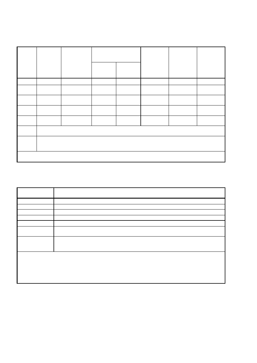
Table A.1 ─ Classification of micro conditions of exposure of completed masonry
Class Micro condition of the masonry
Examples of masonry in this condition
MX1 In a dry environment
Interior of buildings for normal habitation and for
offices, including the inner leaf of external cavity
walls not likely to become damp.
Rendered masonry in exterior walls, not exposed
to moderate or severe driving rain, and isolated
from damp in adjacent masonry or materials.
MX2 Exposed to moisture or wetting
MX2.1 Exposed to moisture but not exposed to
freeze/thaw cycling or external sources of
significant levels of sulfates or aggressive
chemicals
Internal masonry exposed to high levels of water
vapour, such as in a laundry. Masonry exterior
walls sheltered by overhanging eaves or coping,
not exposed to severe driving rain or frost.
Masonry below frost zone in well drained non-
aggressive soil.
MX2.2 Exposed to severe wetting but not exposed to
freeze/thaw cycling or external sources of
significant levels of sulfates or aggressive
chemicals
Masonry not exposed to frost or aggressive
chemicals, located: in exterior walls with cappings
or flush eaves; in parapets; in freestanding walls;
in the ground; under water.
MX3 Exposed to wetting plus freeze/thaw cycling
MX3.1 Exposed to moisture or wetting and freeze/thaw
cycling but not exposed to external sources of
significant levels of sulfates or aggressive
chemicals
Masonry as class MX2.1 exposed to freeze/thaw
cycling.
MX3.2 Exposed to severe wetting and freeze/thaw
cycling but not exposed to external sources of
significant levels of sulfates or aggressive
chemicals
Masonry as class MX2.2 exposed to freeze/thaw
cycling.
MX4 Exposed to saturated salt air, seawater or de-
icing salts
Masonry in a coastal area. Masonry adjacent to
roads that are salted during the winter
MX5 In an aggressive chemical environment
Masonry in contact with natural soils or filled
ground or groundwater, where moisture and
significant levels of sulfates are present.
Masonry in contact with highly acidic soils,
contaminated ground or groundwater. Masonry
near industrial areas where aggressive chemicals
are airborne.
NOTE In deciding the exposure of masonry the effect of applied finishes and protective claddings should be taken into
account.
BS EN 1996-2:2006
Licensed copy: BSI USER 06 Document Controller, Midmac Contracting Co. W.L.L, Version correct as of 03/08/2011 10:43, (c) BSI
EN 1996-2:2006 (E)
27
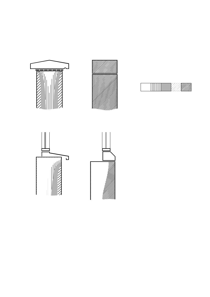
A.2 Exposure to wetting
(1) Figures A.1 and A.2 give examples of relative exposure to wetting.
NOTE The figures are based on typical modern construction but for clarity they do not show all detailing of cavities and
damp proofing.
a) coping with overhang
b) coping without overhang
(simple capping)
Key
Relative exposure to wetting
Protected
Severe
c) sill with overhang
d) sill without overhang
(flush sill)
Figure A.1 ─ Examples of the effect of building detail on
relative exposure to wetting of masonry
BS EN 1996-2:2006
Licensed copy: BSI USER 06 Document Controller, Midmac Contracting Co. W.L.L, Version correct as of 03/08/2011 10:43, (c) BSI
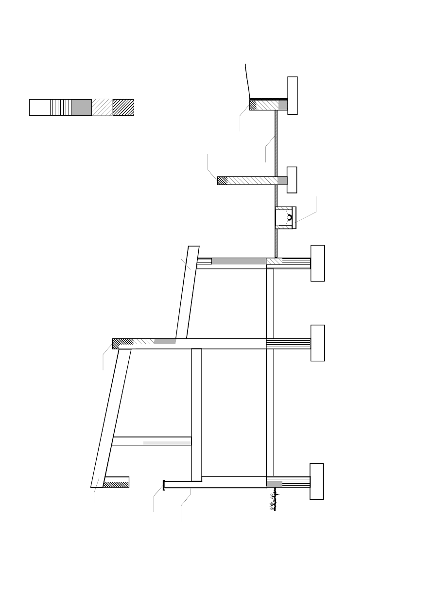
EN 1996-2:2006 (E)
28
Key
Relative exposure to wetting
Protected
Severe
NOTE The extent of the zones of
relative wetting will be affected by
the macro climate
1) flush eaves
2) balcony
3) coping
4) render
5) parapet
6) overhanging eaves
7) inspection chamber
8) freestanding wall
9) paving
10) earth retaining wall
Figure A.2 ─ Examples of relative exposure to wetting of masonry (not protected by applied
finishes or cladding except where indicated, foundation in well drained soil)
1)
2)
3)
4)
5)
6)
7)
8)
9)
10
)
ˆ
‰
BS EN 1996-2:2006
Licensed copy: BSI USER 06 Document Controller, Midmac Contracting Co. W.L.L, Version correct as of 03/08/2011 10:43, (c) BSI

EN 1996-2:2006 (E)
29
ANNEX B
(informative)
Acceptable specifications of masonry units and mortar for durable masonry in
various exposure conditions
B.1 Selection of masonry units and mortar
(1) Masonry units and mortar may be selected from Tables B.1 and B.2, according to the exposure
class of the masonry determined from Table A.1.
(2) Masonry mortar is specified for durability using the terms defined in EN 998-2. For the purposes
of Table B.2 they are abbreviated using the following symbols:
P - mortar for use in masonry subjected to passive exposure;
M - mortar for use in masonry subjected to moderate exposure;
S - mortar for use in masonry subjected to severe exposure.
(3) Until a European test method is available, the designation of site-made mortar mix prescriptions,
for which authoritative data are available, may be related to the P, M, or S designations.
(4) In addition to selecting a mortar for durability, other performance characteristics such as
compressive strength, bond strength, and water retentivity need to be taken into account so that the
mortar is compatible with the selected masonry units and enables the masonry to satisfy all relevant
design requirements.
(5) In the present state of the art guidance on the suitability of mortars will generally need to be
obtained from the manufacturers of factory made mortars or in the case of site-made mortars from
authoritative sources accepted in the place of use, see 2.2.3.
BS EN 1996-2:2006
Licensed copy: BSI USER 06 Document Controller, Midmac Contracting Co. W.L.L, Version correct as of 03/08/2011 10:43, (c) BSI
EN 1996-2:2006 (E)
30
Table B.1 ─ Acceptable specifications of masonry units for durability
Aggregate concrete
masonry units
conforming to EN771-3
Exposure
class
(see
Table
A.1)
Clay
masonry
units
conforming
to EN771-1
Calcium silicate
masonry units
conforming to
EN771-2
Dense
aggregate
Lightweight
aggregate
Autoclaved
aerated
concrete
masonry units
conforming to
EN771-4
Manufactured
stone masonry
units
conforming to
EN771-5
Natural stone
masonry units
conforming to
EN771-6
MX1
a
Any
Any
Any
Any
Any
Any
Any
MX2.1
F0, F1 or F2
/ S1 or S2
Any
Any
Any
Any
Any
Any
MX2.2
F0, F1 or F2
/ S1 or S2
Any
Any
Any
≥ 400 kg/m
3
Any
Any
MX3.1
F1 or F2 / S1
or S2
Freeze/thaw
resistant
Freeze/thaw
resistant
Freeze/thaw
resistant
≥ 400 kg/m
3
Any
Consult
manufacturer
MX3.2
F2 / S1 or S2
Freeze/thaw
resistant
Freeze/thaw
resistant
Freeze/thaw
resistant
≥ 400 kg/m
3
Any
Consult
manufacturer
MX4
In each case assess the degree of exposure to salts, wetting and freeze/thaw cycling and consult the
manufacturer.
MX5
In each case a specific assessment should be made of the environment and the effect of the chemicals
involved taking into account concentrations, quantities available and rates of reaction and consult the
manufacturer
a
Class MX1 is valid only as long as the masonry, or any of its components, is not exposed during execution to more
severe conditions over a prolonged period of time.
Table B.2 ─ Acceptable specifications of mortars for durability
Exposure class
(see Table A.1)
Mortar in combination with any type of unit, classified according to B.1(2)
MX1
a,b
P,M,or S
MX2.1
M,or S
MX2.2
M or S
c
MX3.1
M or S
MX3.2
S
c
MX4
In each case assess the degree of exposure to salts, wetting and freeze/thaw cycling and consult
the manufacturers of the constituent materials.
MX5
In each case a specific assessment should be made of the environment and the effect of the
chemicals involved taking into account concentrations, quantities available and rates of reaction
and consult the manufacturers of the constituent materials.
a
Class MX1 is valid only as long as the masonry, or any of its components, is not exposed during execution to more
severe conditions over a prolonged period of time.
b
When designation P mortars are specified it is essential to ensure that masonry units, mortar and masonry under
construction are fully protected from saturation and freezing.
c
When clay masonry units of Soluble Salts Content Category S1 is to be used in masonry where the Exposure Class
is MX2.2, MX3.2, MX4 and MX5 the mortars should in addition be sulfate resisting
BS EN 1996-2:2006
Licensed copy: BSI USER 06 Document Controller, Midmac Contracting Co. W.L.L, Version correct as of 03/08/2011 10:43, (c) BSI

EN 1996-2:2006 (E)
31
ANNEX C
(informative)
Selection of material and corrosion protection specifications for ancillary
components according to exposure class
C.1 Exposure classes
(1) The range of environmental conditions encountered by ancillary components is classified into the
five exposure classes MX1, MX2, MX3, MX4 and MX5 as given in Table A.1.
(2) The choice of exposure class should take into account either the exposure of products during
execution or in the finished work, whichever will be the more onerous.
C.2 Selection of materials
(1) The material and protective coating, if any, for ancillary components can be selected from the
relevant part of EN 845.
(2) Materials for the manufacture of ancillary components and their corrosion protection systems are
specified in full in the relevant part of EN 845 and each one is given a unique material/coating reference.
This reference gives no indication of relative performance or quality.
(3) Materials for ties, tension straps, hangers and brackets, conforming to EN 845-1, can be selected
using Table C.1.
(4) Materials for lintels, conforming to EN 845-2, can be selected using Table C.2.
(5) Materials for bed joint reinforcement, conforming to EN 845-3 can be selected using Table C.3.
(6) Tables C.1, C.2 and C.3 show the material/coating reference with a brief description of the materials
and the exposure classes, in which the specification is suitable. This guidance is based on long term
experience of the durability of such materials in a range of exposure conditions. Currently there is no
accepted accelerated exposure test for measuring this parameter.
(7) Materials allocated to each exposure class will be expected to have an economically reasonable
working life under the conditions described, subject to specialist advice being obtained in some cases, as
indicated in the table. The choice will be dependent upon the particular application, its location and the
intended working life.
(8) Where ancillary components need to be movement tolerant during installation or use, the ability of
the materials and coatings to withstand the expected movement ought to be taken into account.
BS EN 1996-2:2006
Licensed copy: BSI USER 06 Document Controller, Midmac Contracting Co. W.L.L, Version correct as of 03/08/2011 10:43, (c) BSI

EN 1996-2:2006 (E)
32
Table C.1 ─ Corrosion protection systems for ties, tension straps, brackets and hangers
conforming to EN 845-1 in relation to exposure classes
Material
a
Ref.
Exposure class
No. MX1 MX2 MX3 MX4 MX5
Austenitic stainless steel (molybdenum chrome nickel alloys)
1
U
U
U
U
R
Plastic used for the body of ties
2
U
U
U
U
R
Austenitic stainless steel (chrome nickel alloys)
3
U
U
U
R
R
Ferritic stainless steel
4
U
X
X
X
X
Phosphor bronze
5
U
U
U
X
X
Aluminium bronze
6
U
U
U
X
X
Copper
7
U
U
U
X
X
Zinc coated (940 g/m²) steel wire
8
U
U
U
R
X
Zinc coated (940 g/m²) steel component
9
U
U
U
R
X
Zinc coated (710 g/m²) steel component
10
U
U
U
R
X
Zinc coated (460 g/m²) steel component
11
U
R
R
R
X
Zinc coated (300 g/m²) steel strip or sheet with organic coating
over all outer surfaces of finished component
12.1
U
U
U
R
X
Zinc coated (300 g/m²) steel strip or sheet with organic coating
over all outer surfaces of finished component
12.2
U
U
U
R
X
Zinc coated (265 g/m²) steel wire
13
U
R
R
X
X
Zinc coated (300 g/m²) steel strip or sheet with all cut edges
organic coated
14
U
R
R
X
X
Zinc pre-coated (300 g/m²) steel strip or sheet
15
U
R
R
X
X
Zinc coated (137 g/m²) steel strip or sheet with organic coating
over all outer surfaces of finished component
16.1
U
U
U
R
X
Zinc coated (137 g/m²) steel strip or sheet with organic coating
over all outer surfaces of finished component
16.2
U
U
U
R
X
Zinc pre-coated (137 g/m²) steel strip with zinc coated edges
17
U
R
R
X
X
Zinc coated (60 g/m²) steel wire with organic coating over all
surfaces of finished component
18
U
R
R
R
X
Zinc coated (105 g/m²) steel wire
19
U
R
R
X
X
Zinc coated (60 g/m²) steel wire
20
U
X
X
X
X
Zinc pre-coated (137 g/m²) steel sheet
21
U
X
X
X
X
KEY:
U - unrestricted use of the material in listed class of exposure.
R - restricted use; consult the manufacturer or a specialist consultant for advice for the specific
design conditions.
X - material not recommended for use in this exposure class.
a
The full specification of the material and coating or concrete cover corresponding to the
reference number or letter is given in EN 845-1. The coating weights shown are approximate values for
one surface.
BS EN 1996-2:2006
Licensed copy: BSI USER 06 Document Controller, Midmac Contracting Co. W.L.L, Version correct as of 03/08/2011 10:43, (c) BSI
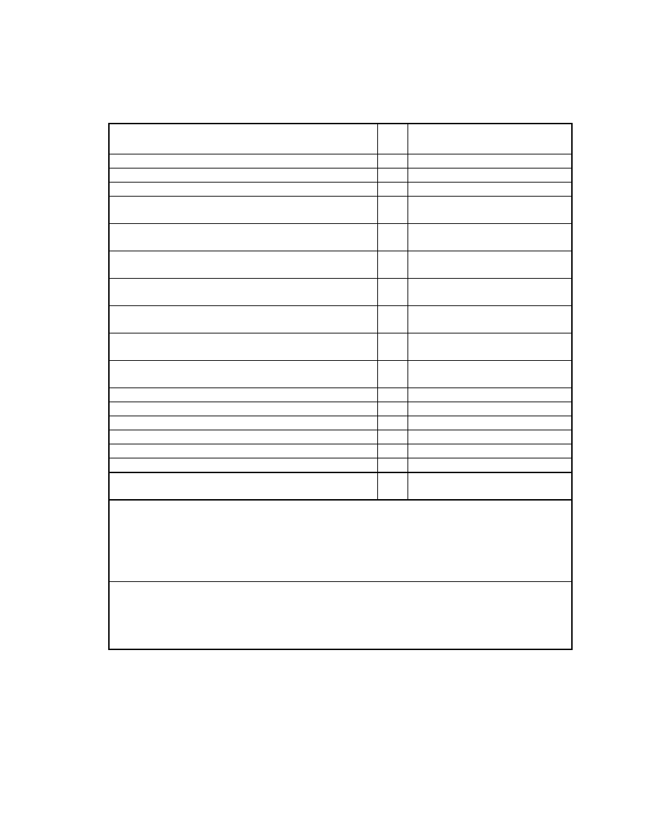
EN 1996-2:2006 (E)
33
Table C.2 ─ Corrosion protection systems for lintels
conforming to EN 845-2 in relation to exposure classes
Material
a
Ref.
Exposure class
No. MX1 MX2 MX3 MX4 MX5
Austenitic stainless steel (chrome nickel alloys)
L3
U
U
U
R
R
Zinc coated (710 g/m²) steel component
L10
U
U
U
R
X
Zinc coated (460 g/m²) steel component
L11
U
D
D
R
X
Zinc coated (460 g/m²) steel component with organic
coating on specified upper surfaces
L11.1
U
U
U
R
X
Zinc coated (460 g/m²) steel component with organic
coating on specified upper surfaces
L11.2
U
U
U
R
X
Zinc coated (300 g/m²) steel strip or sheet with organic
coating over all outer surfaces of finished component
L12.1
U
U
U
R
X
Zinc coated (300 g/m²) steel strip or sheet with organic
coating over all outer surfaces of finished component
L12.2
U
U
U
R
X
Zinc coated (300 g/m²) steel strip or sheet with all cut
edges organic coated
L14
U
D
D
R
X
Zinc coated (137 g/m²) steel strip or sheet with organic
coating over all outer surfaces of finished component
L16.1
U
D
D
R
X
Zinc coated (137 g/m²) steel strip or sheet with organic
coating over all outer surfaces of finished component
L16.2
U
U
U
R
X
Concrete
b
or concrete and masonry
A
U
U
R
R
R
Concrete
b
or concrete and masonry
B
U
U
R
R
X
Concrete
b
or concrete and masonry
C
U
U
R
X
X
Concrete
b
or concrete and masonry
D
U
U
X
X
X
Concrete
b
or concrete and masonry
E
U
X
X
X
X
Concrete
b
or masonry with stainless steel reinforcement
F
U
U
R
R
R
Autoclaved aerated concrete with reinforcement
protected by a coating system
G
U
R
R
R
R
KEY:
U - unrestricted use of the material in listed class of exposure.
R - restricted use; consult the manufacturer or a specialist consultant for advice for the
specific design conditions.
D - with a damp proof course on top of the lintel the use is unrestricted (U). Without a
damp proof course on top of the lintel the use is restricted (R)
X - material not recommended for use in this exposure class.
a
The full specification of the material and coating or concrete cover corresponding to the
reference number or letter is given in EN 845-2. The coating weights shown are approximate
values for one surface.
b
The manufacturer, or a specialist consultant, may permit a less restrictive use for prefabricated
lintels, based on local experience'
BS EN 1996-2:2006
Licensed copy: BSI USER 06 Document Controller, Midmac Contracting Co. W.L.L, Version correct as of 03/08/2011 10:43, (c) BSI
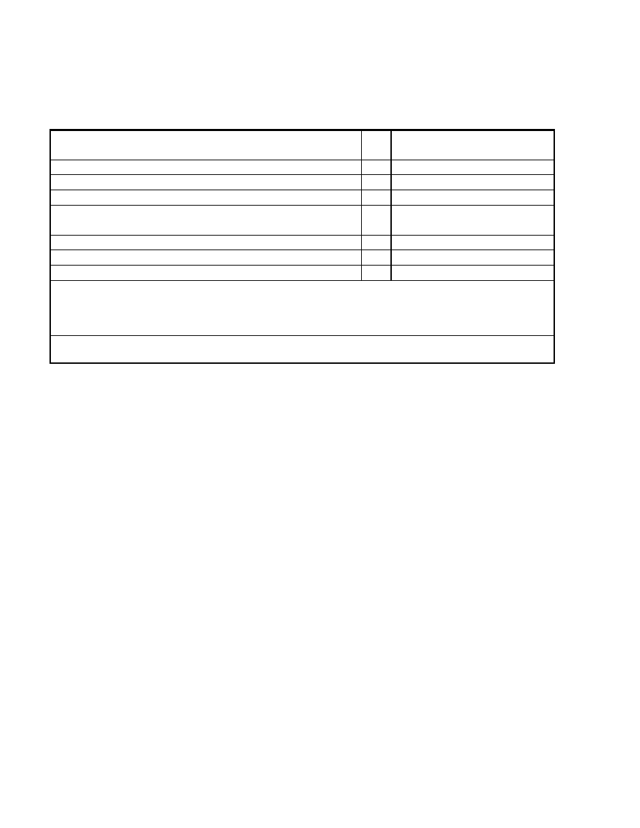
EN 1996-2:2006 (E)
34
Table C.3 ─ Corrosion protection systems for bed joint reinforcement
conforming to EN 845-3 in relation to exposure classes
Material
a
Ref.
Exposure class
No. MX1 MX2 MX3 MX4 MX5
Austenitic stainless steel (molybdenum chrome nickel alloys) R1
U
U
U
U
R
Austenitic stainless steel (chrome nickel alloys)
R3
U
U
U
R
R
Zinc coated (265 g/m²) steel wire
R13
U
R
R
X
X
Zinc coated (60 g/m²) steel wire with organic coating over all
surfaces of finished component
R18
U
U
U
R
X
Zinc coated (105 g/m²) steel wire
R19
U
R
R
X
X
Zinc coated (60 g/m²) steel wire
R20
U
X
X
X
X
Zinc pre-coated (137 g/m²) steel sheet
R21
U
X
X
X
X
KEY:
U - unrestricted use of the material in listed class of exposure.
R - restricted use; consult the manufacturer or a specialist consultant for advice for the specific
design conditions.
X - material not recommended for use in this exposure class.
a
The full specification of the material and coating or concrete cover corresponding to the reference
number or letter is given in EN 845-3. The coating weights shown are approximate values for one surface.
BS EN 1996-2:2006
Licensed copy: BSI USER 06 Document Controller, Midmac Contracting Co. W.L.L, Version correct as of 03/08/2011 10:43, (c) BSI

blank
Licensed copy: BSI USER 06 Document Controller, Midmac Contracting Co. W.L.L, Version correct as of 03/08/2011 10:43, (c) BSI

BSI Group
Headquarters 389
Chiswick High Road,
London, W4 4AL, UK
Tel +44 (0)20 8996 9001
Fax +44 (0)20 8996 7001
www.bsigroup.com/
standards
BSI - British Standards Institution
BSI is the independent national body responsible for preparing British
Standards. It presents the UK view on standards in Europe and at the
international level. It is incorporated by Royal Charter.
Revisions
British Standards are updated by amendment or revision. Users of British
Standards should make sure that they possess the latest amendments or
editions.
It is the constant aim of BSI to improve the quality of our products and services.
We would be grateful if anyone finding an inaccuracy or ambiguity while using
this British Standard would inform the Secretary of the technical committee
responsible, the identity of which can be found on the inside front cover. Tel:
+44 (0)20 8996 9000. Fax: +44 (0)20 8996 7400.
BSI offers members an individual updating service called PLUS which ensures
that subscribers automatically receive the latest editions of standards.
Buying standards
Orders for all BSI, international and foreign standards publications should be
addressed to Customer Services. Tel: +44 (0)20 8996 9001. Fax: +44 (0)20 8996
7001 Email: orders@bsigroup.com You may also buy directly using a debit/credit
card from the BSI Shop on the Website http://www.bsigroup.com/shop
In response to orders for international standards, it is BSI policy to supply the
BSI implementation of those that have been published as British Standards,
unless otherwise requested.
Information on standards
BSI provides a wide range of information on national, European and
international standards through its Library and its Technical Help to Exporters
Service. Various BSI electronic information services are also available which
give details on all its products and services. Contact Information Centre. Tel:
+44 (0)20 8996 7111 Fax: +44 (0)20 8996 7048 Email: info@bsigroup.com
Subscribing members of BSI are kept up to date with standards developments
and receive substantial discounts on the purchase price of standards. For details
of these and other benefits contact Membership Administration. Tel: +44 (0)20
8996 7002 Fax: +44 (0)20 8996 7001 Email: membership@bsigroup.com
Information regarding online access to British Standards via British Standards
Online can be found at http://www.bsigroup.com/BSOL
Further information about BSI is available on the BSI website at http://
www.bsigroup.com
Copyright
Copyright subsists in all BSI publications. BSI also holds the copyright, in the
UK, of the publications of the international standardization bodies. Except as
permitted under the Copyright, Designs and Patents Act 1988 no extract may
be reproduced, stored in a retrieval system or transmitted in any form or by any
means – electronic, photocopying, recording or otherwise – without prior written
permission from BSI.
This does not preclude the free use, in the course of implementing the standard,
of necessary details such as symbols, and size, type or grade designations. If
these details are to be used for any other purpose than implementation then the
prior written permission of BSI must be obtained.
Details and advice can be obtained from the Copyright and Licensing Manager.
Tel: +44 (0)20 8996 7070 Email: copyright@bsigroup.com
BS EN
1996-2:2006
Licensed copy: BSI USER 06 Document Controller, Midmac Contracting Co. W.L.L, Version correct as of 03/08/2011 10:43, (c) BSI
Wyszukiwarka
Podobne podstrony:
Eurocode 6 Part 2 1996 2006 Design of Masonry Structures Design Considerations, Selection of Mat
Eurocode 6 Part 3 1996 2006 Design of Masonry Structures Simplified Calculation Methods for Maso
Eurocode 6 Part 1 2 1996 2005 Design of Masonry Structures General Rules Structural Fire Design
Eurocode 6 Part 1 1 1996 2005 Design of Masonry Structures General Rules for Reinforced and Unre
Eurocode 3 Part 1 11 2006 Design of Steel Structures Design of Structures With Tension Components
Eurocode 8 Part 4 1998 2006 Design of tructures for Earthquake Resistance Silos, Tanks and Pipe
Eurocode 8 Part 1 1998 2004 Design of Structures for Earthquake Resistance General Rules Seism
Eurocode 8 Part 5 1998 2004 Design of Structures for Earthquake Resistance Foundations, Retaini
Eurocode 8 Part 6 1998 2005 Design of Structures for Earthquake Resistance Towers, Masts and Ch
Eurocode 8 Part 5 1998 2004 Design of Structures for Earthquake Resistance Foundations, Retaini
Eurocode 5 Part 1 2 1995 2004 Design of Timber Structures General Structural Fire Design UK Ann
Eurocode 9 Part 1 3 1999 2007 Design of Aluminium Structures Structures Susceptible to Fatigue
Eurocode 5 Part 2 1995 2004 Design of timber structures Bridges
Eurocode 8 Part 6 1998 2005 Design of Structures for Earthquake Resistance Towers, Masts and Ch
Eurocode 9 Part 1 2 1999 2007 Design of Aluminium Structures Structural Fire Design UK NA
Eurocode 3 Part 1 12 2007 Design of Steel Structures Additional Rules for the Extension of EN 199
Eurocode 9 Part 1 4 1999 2007 Design of Aluminium Structures Cold formed Structural Sheeting UK
Eurocode 1 Part 1 6 2005 UK NA Actions on Structures General actions Actions during execution
Eurocode 1 Part 1 1 2002 UK NA Actions on Structures General actions Densities, self weight, imp
więcej podobnych podstron