
EUROPEAN STANDARD
NORME EUROPÉENNE
EUROPÄISCHE NORM
FINAL DRAFT
prEN 1995-1-1
December 2003
ICS 91.010.30
Will supersede ENV 1995-1-1:1993
English version
Eurocode 5 - Design of timber structures - Part 1-1: General -
Common rules and rules for buildings
Eurocode 5 - Conception et calcul des structures en bois -
Partie 1-1: Généralités - Règles communes et règles pour
les bâtiments
Eurocode 5 - Bemessung und Konstruktion von Holzbauten
- Teil 1-1: Allgemeines - Allgemeine Regeln und Regeln für
den Hochbau
This draft European Standard is submitted to CEN members for formal vote. It has been drawn up by the Technical Committee CEN/TC
250.
If this draft becomes a European Standard, CEN members are bound to comply with the CEN/CENELEC Internal Regulations which
stipulate the conditions for giving this European Standard the status of a national standard without any alteration.
This draft European Standard was established by CEN in three official versions (English, French, German). A version in any other
language made by translation under the responsibility of a CEN member into its own language and notified to the Management Centre has
the same status as the official versions.
CEN members are the national standards bodies of Austria, Belgium, Czech Republic, Denmark, Finland, France, Germany, Greece,
Hungary, Iceland, Ireland, Italy, Luxembourg, Malta, Netherlands, Norway, Portugal, Slovakia, Spain, Sweden, Switzerland and United
Kingdom.
Warning : This document is not a European Standard. It is distributed for review and comments. It is subject to change without notice and
shall not be referred to as a European Standard.
EUROPEAN COMMITTEE FOR STANDARDIZATION
C O M I T É E U R O P É E N D E N O R M A L I S A T I O N
E U R O P Ä I S C H E S K O M I T E E F Ü R N O R M U N G
Management Centre: rue de Stassart, 36 B-1050 Brussels
© 2003 CEN
All rights of exploitation in any form and by any means reserved
worldwide for CEN national Members.
Ref. No. prEN 1995-1-1:2003 E

prEN 1995-1-1:2003 (E)
2
Contents Page
FOREWORD
7
SECTION 1
GENERAL 10
1.1
S
COPE
10
1.1.1
Scope of Eurocode 5
10
1.1.2
Scope of EN 1995-1-1
10
1.2
N
ORMATIVE REFERENCES
11
1.3
A
SSUMPTIONS
13
1.4
D
ISTINCTION BETWEEN
P
RINCIPLES AND
A
PPLICATION
R
ULES
13
1.5
D
EFINITIONS
14
1.5.1
General 14
1.5.2
Additional terms and definitions used in EN 1995-1-1
14
1.6
S
YMBOLS USED IN
EN
1995-1-1 15
SECTION 2
BASIS OF DESIGN
20
2.1
R
EQUIREMENTS
20
2.1.1
Basic requirements
20
2.1.2
Reliability management
20
2.1.3
Design working life and durability
20
2.2
P
RINCIPLES OF LIMIT STATE DESIGN
20
2.2.1
General 20
2.2.2
Ultimate limit states
20
2.2.3
Serviceability limit states
21
2.3
B
ASIC VARIABLES
21
2.3.1
Actions and environmental influences
21
2.3.1.1
General
21
2.3.1.2
Load-duration classes
22
2.3.1.3
Service classes
22
2.3.2
Materials and product properties
23
2.3.2.1
Load-duration and moisture influences on strength
23
2.3.2.2
Load-duration and moisture influences on deformations
23
2.4
V
ERIFICATION BY THE PARTIAL FACTOR METHOD
24
2.4.1
Design value of material property
24
2.4.2
Design value of geometrical data
25
2.4.3
Design resistances
25
2.4.4
Verification of equilibrium (EQU)
25
SECTION 3
MATERIAL PROPERTIES
26
3.1
G
ENERAL
26
3.1.1
Strength and stiffness parameters
26
3.1.2
Stress-strain relations
26
3.1.3
Strength modification factors for service classes and load-duration classes
26
3.1.4
Deformation modification factors for service classes
26
3.2
S
OLID TIMBER
26
3.3
G
LUED LAMINATED TIMBER
27
3.4
L
AMINATED VENEER LUMBER
(LVL) 28
3.5
W
OOD
-
BASED PANELS
29
3.6
A
DHESIVES
29
3.7
M
ETAL FASTENERS
29
SECTION 4
DURABILITY 30
4.1
R
ESISTANCE TO BIOLOGICAL ORGANISMS
30
4.2
R
ESISTANCE TO CORROSION
30
SECTION 5
BASIS OF STRUCTURAL ANALYSIS
31
5.1
G
ENERAL
31

prEN 1995-1-1:2003 (E)
3
5.2
M
EMBERS
31
5.3
C
ONNECTIONS
31
5.4
A
SSEMBLIES
32
5.4.1
General 32
5.4.2
Frame structures
32
5.4.3
Simplified analysis of trusses with punched metal plate fasteners
33
5.4.4
Plane frames and arches
34
SECTION 6
ULTIMATE LIMIT STATES
36
6.1
D
ESIGN OF CROSS
-
SECTIONS SUBJECTED TO STRESS IN ONE PRINCIPAL DIRECTION
36
6.1.1
General 36
6.1.2
Tension parallel to the grain
36
6.1.3
Tension perpendicular to the grain
36
6.1.4
Compression parallel to the grain
36
6.1.5
Compression perpendicular to the grain
36
6.1.6
Bending 41
6.1.7
Shear
41
6.1.8
Torsion 42
6.2
D
ESIGN OF CROSS
-
SECTIONS SUBJECTED TO COMBINED STRESSES
43
6.2.1
General 43
6.2.2
Compression stresses at an angle to the grain
43
6.2.3
Combined bending and axial tension
43
6.2.4
Combined bending and axial compression
43
6.3
S
TABILITY OF MEMBERS
44
6.3.1
General 44
6.3.2
Columns subjected to either compression or combined compression and
bending 44
6.3.3
Beams subjected to either bending or combined bending and compression
45
6.4
D
ESIGN OF CROSS
-
SECTIONS IN MEMBERS WITH VARYING CROSS
-
SECTION OR CURVED
SHAPE
47
6.4.1
General 47
6.4.2
Single tapered beams
47
6.4.3
Double tapered, curved and pitched cambered beams
48
6.5
N
OTCHED MEMBERS
52
6.5.1
General 52
6.5.2
Beams with a notch at the support
52
6.6
S
YSTEM STRENGTH
53
SECTION 7
SERVICEABILITY LIMIT STATES
55
7.1
J
OINT SLIP
55
7.2
L
IMITING VALUES FOR DEFLECTIONS OF BEAMS
55
7.3
V
IBRATIONS
56
7.3.1
General 56
7.3.2
Vibrations from machinery
56
7.3.3
Residential floors
56
SECTION 8
CONNECTIONS WITH METAL FASTENERS
59
8.1
G
ENERAL
59
8.1.1
Fastener requirements
59
8.1.2
Multiple fastener connections
59
8.1.3
Multiple shear plane connections
59
8.1.4
Connection forces at an angle to the grain
59
8.1.5
Alternating connection forces
61
8.2
L
ATERAL LOAD
-
CARRYING CAPACITY OF METAL DOWEL
-
TYPE FASTENERS
61
8.2.1
General 61
8.2.2
Timber-to-timber and panel-to-timber connections
61
8.2.3
Steel-to-timber connections
63
8.3
N
AILED CONNECTIONS
65

prEN 1995-1-1:2003 (E)
4
8.3.1
Laterally loaded nails
65
8.3.1.1
General
65
8.3.1.2
Nailed timber-to-timber connections
67
8.3.1.3
Nailed panel-to-timber connections
70
8.3.1.4
Nailed steel-to-timber connections
70
8.3.2
Axially loaded nails
70
8.3.3
Combined laterally and axially loaded nails
72
8.4
S
TAPLED CONNECTIONS
72
8.5
B
OLTED CONNECTIONS
74
8.5.1
Laterally loaded bolts
74
8.5.1.1
General and bolted timber-to-timber connections
74
8.5.1.2
Bolted panel-to-timber connections
76
8.5.1.3
Bolted steel-to-timber connections
76
8.5.2
Axially loaded bolts
76
8.6
D
OWELLED CONNECTIONS
76
8.7
S
CREWED CONNECTIONS
77
8.7.1
Laterally loaded screws
77
8.7.2
Axially loaded screws
77
8.7.3
Combined laterally and axially loaded screws
79
8.8
C
ONNECTIONS MADE WITH PUNCHED METAL PLATE FASTENERS
79
8.8.1
General 79
8.8.2
Plate geometry
79
8.8.3
Plate strength properties
79
8.8.4
Plate anchorage strengths
80
8.8.5
Connection strength verification
81
8.8.5.1
Plate anchorage capacity
81
8.8.5.2
Plate capacity
82
8.9
S
PLIT RING AND SHEAR PLATE CONNECTORS
83
8.10
T
OOTHED
-
PLATE CONNECTORS
86
SECTION 9
COMPONENTS AND ASSEMBLIES
89
9.1
C
OMPONENTS
89
9.1.1
Glued thin-webbed beams
89
9.1.2
Glued thin-flanged beams
91
9.1.3
Mechanically jointed beams
92
9.1.4
Mechanically jointed and glued columns
93
9.2
A
SSEMBLIES
93
9.2.1
Trusses 93
9.2.2
Trusses with punched metal plate fasteners
94
9.2.3
Roof and floor diaphragms
95
9.2.3.1
General
95
9.2.3.2
Simplified analysis of roof and floor diaphragms.
95
9.2.4
Wall diaphragms
96
9.2.4.1
General
96
9.2.4.2
Simplified analysis of wall diaphragms – Method A
96
9.2.4.3
Simplified analysis of wall diaphragms – Method B
99
9.2.4.3.1
Construction of walls and panels to meet the requirements of the simplified
analysis
99
9.2.4.3.2
Design procedure
100
9.2.5
Bracing 102
9.2.5.1
General
102
9.2.5.2
Single members in compression
102
9.2.5.3
Bracing of beam or truss systems
103
SECTION 10
STRUCTURAL DETAILING AND CONTROL
105
10.1
G
ENERAL
105
10.2
M
ATERIALS
105
10.3
G
LUED JOINTS
105
10.4
C
ONNECTIONS WITH MECHANICAL FASTENERS
105
10.4.1
General 105

prEN 1995-1-1:2003 (E)
5
10.4.2
Nails 105
10.4.3
Bolts and washers
105
10.4.4
Dowels 106
10.4.5
Screws 106
10.5
A
SSEMBLY
106
10.6
T
RANSPORTATION AND ERECTION
106
10.7
C
ONTROL
107
10.8
S
PECIAL RULES FOR DIAPHRAGM STRUCTURES
107
10.8.1
Floor and roof diaphragms
107
10.8.2
Wall diaphragms
108
10.9
S
PECIAL RULES FOR TRUSSES WITH PUNCHED METAL PLATE FASTENERS
108
10.9.1
Fabrication 108
10.9.2
Erection 108
ANNEX A
(INFORMATIVE): BLOCK SHEAR AND PLUG SHEAR FAILURE AT
MULTIPLE DOWEL-TYPE STEEL-TO-TIMBER CONNECTIONS
110
ANNEX B
(INFORMATIVE): MECHANICALLY JOINTED BEAMS
112
B.1
S
IMPLIFIED ANALYSIS
112
B.1.1
Cross-sections 112
B.1.2
Assumptions 112
B.1.3
Spacings 112
B.1.4
Deflections resulting from bending moments
112
B.2
E
FFECTIVE BENDING STIFFNESS
114
B.3
N
ORMAL STRESSES
114
B.4
M
AXIMUM SHEAR STRESS
114
B.5
F
ASTENER LOAD
114
ANNEX C
(INFORMATIVE): BUILT-UP COLUMNS
116
C.1
G
ENERAL
116
C.1.1
Assumptions 116
C.1.2
Load-carrying capacity
116
C.2
M
ECHANICALLY JOINTED COLUMNS
116
C.2.1
Effective slenderness ratio
116
C.2.2
Load on fasteners
116
C.2.3
Combined loads
117
C.3
S
PACED COLUMNS WITH PACKS OR GUSSETS
117
C.3.1
Assumptions 117
C.3.2
Axial load-carrying capacity
118
C.3.3
Load on fasteners, gussets or packs
119
C.4
L
ATTICE COLUMNS WITH GLUED OR NAILED JOINTS
119
C.4.1
Assumptions 119
C.4.2
Load-carrying capacity
120
C.4.3
Shear forces
122
ANNEX D (INFORMATIVE): BIBLIOGRAPHY
123


prEN 1995-1-1:2003 (E)
7
Foreword
This document (EN 1995-1-1:2004) has been prepared by Technical Committee CEN/TC250
“Structural Eurocodes”, the Secretariat of which is held by BSI.
This standard shall be given the status of a national standard, either by publication of an
identical text or by endorsement, at the latest by [month year], and conflicting national standards
shall be withdrawn at the latest by [month year].
This European Standard supersedes ENV 1995-1-1:1993.
CEN/TC250 is responsible for all Structural Eurocodes.
Background of the Eurocode programme
In 1975, the Commission of the European Community decided on an action programme in the
field of construction, based on article 95 of the Treaty. The objective of the programme was the
elimination of technical obstacles to trade and the harmonisation of technical specifications.
Within this action programme, the Commission took the initiative to establish a set of
harmonised technical rules for the design of construction works which, in a first stage, would
serve as an alternative to the national rules in force in the Member States and, ultimately, would
replace them.
For fifteen years, the Commission, with the help of a Steering Committee with Representatives
of Member States, conducted the development of the Eurocodes programme, which led to the
first generation of European codes in the 1980s.
In 1989, the Commission and the Member States of the EU and EFTA decided, on the basis of
an agreement
1
between the Commission and CEN, to transfer the preparation and the
publication of the Eurocodes to CEN through a series of Mandates, in order to provide them
with a future status of European Standard (EN). This links de facto the Eurocodes with the
provisions of all the Council’s Directives and/or Commission’s Decisions dealing with European
standards (e.g. the Council Directive 89/106/EEC on construction products – CPD – and
Council Directives 93/37/EEC, 92/50/EEC and 89/440/EEC on public works and services and
equivalent EFTA Directives initiated in pursuit of setting up the internal market).
The Structural Eurocode programme comprises the following standards generally consisting of
a number of Parts:
EN 1990:2002
Eurocode: Basis of Structural Design
EN 1991
Eurocode 1: Actions on structures
EN 1992
Eurocode 2: Design of concrete structures
EN 1993
Eurocode 3: Design of steel structures
EN 1994
Eurocode 4: Design of composite steel and concrete structures
EN 1995
Eurocode 5: Design of timber structures
EN 1996
Eurocode 6: Design of masonry structures
EN 1997
Eurocode 7: Geotechnical design
EN 1998
Eurocode 8: Design of structures for earthquake resistance
EN 1999
Eurocode 9: Design of aluminium structures
Eurocode standards recognise the responsibility of regulatory authorities in each Member State
and have safeguarded their right to determine values related to regulatory safety matters at
national level where these continue to vary from State to State.
1
Agreement between the Commission of the European Communities and the European Committee for
Standardisation (CEN) concerning the work on EUROCODES for the design of building and civil
engineering works (BC/CEN/03/89).

prEN 1995-1-1:2003 (E)
8
Status and field of application of Eurocodes
The Member States of the EU and EFTA recognise that Eurocodes serve as reference
documents for the following purposes:
– as a means to prove compliance of building and civil engineering works with the essential
requirements of Council Directive 89/106/EEC, particularly Essential Requirement N°1 –
Mechanical resistance and stability – and Essential Requirement N°2 – Safety in case of fire ;
– as a basis for specifying contracts for construction works and related engineering services ;
– as a framework for drawing up harmonised technical specifications for construction products
(ENs and ETAs)
The Eurocodes, as far as they concern the construction works themselves, have a direct
relationship with the Interpretative Documents
2
referred to in Article 12 of the CPD, although
they are of a different nature from harmonised product standards
3
. Therefore, technical aspects
arising from the Eurocodes work need to be adequately considered by CEN Technical
Committees and/or EOTA Working Groups working on product standards with a view to
achieving full compatibility of these technical specifications with the Eurocodes.
The Eurocode standards provide common structural design rules for everyday use for the
design of whole structures and component products of both a traditional and an innovative
nature. Unusual forms of construction or design conditions are not specifically covered and
additional expert consideration will be required by the designer in such cases.
National Standards implementing Eurocodes
The National Standards implementing Eurocodes will comprise the full text of the Eurocode
(including any annexes), as published by CEN, which may be preceded by a National title page
and National foreword, and may be followed by a National annex.
The National annex may only contain information on those parameters which are left open in
the Eurocode for national choice, known as Nationally Determined Parameters, to be used for
the design of buildings and civil engineering works to be constructed in the country concerned,
i.e.:
– values and/or classes where alternatives are given in the Eurocode;
– values to be used where a symbol only is given in the Eurocode;
– country specific data (geographical, climatic, etc.), e.g. snow map;
– the procedure to be used where alternative procedures are given in the Eurocode;
– decisions on the application of informative annexes;
– references to non-contradictory complementary information to assist the user to apply the
Eurocode.
2
According to Art. 3.3 of the CPD, the essential requirements (ERs) shall be given concrete form in
interpretative documents for the creation of the necessary links between the essential requirements and
the mandates for harmonised ENs and ETAGs/ETAs.
3
According to Art. 12 of the CPD the interpretative documents shall:
give concrete form to the essential requirements by harmonising the terminology and the technical bases
and indicating classes or levels for each requirement where necessary ;
indicate methods of correlating these classes or levels of requirement with the technical specifications, e.g.
methods of calculation and of proof, technical rules for project design, etc. ;
serve as a reference for the establishment of harmonised standards and guidelines for European technical
approvals.
The Eurocodes, de facto, play a similar role in the field of the ER 1 and a part of ER 2.

prEN 1995-1-1:2003 (E)
9
Links between Eurocodes and harmonised technical specifications (ENs and ETAs) for
products
There is a need for consistency between the harmonised technical specifications for
construction products and the technical rules for works
4
. Furthermore, all the information
accompanying the CE Marking of the construction products which refer to Eurocodes shall
clearly mention which Nationally Determined Parameters have been taken into account.
Additional information specific to EN 1995-1-1
EN 1995 describes the Principles and requirements for safety, serviceability and durability of
timber structures. It is based on the limit state concept used in conjunction with a partial factor
method.
For the design of new structures, EN 1995 is intended to be used, for direct application,
together with EN 1990:2002 and relevant Parts of EN 1991.
Numerical values for partial factors and other reliability parameters are recommended as basic
values that provide an acceptable level of reliability. They have been selected assuming that an
appropriate level of workmanship and of quality management applies. When EN 1995-1-1 is
used as a base document by other CEN/TCs the same values need to be taken.
National annex for EN 1995-1-1
This standard gives alternative procedures, values and recommendations with notes indicating
where national choices may have to be made. Therefore the National Standard implementing
EN 1995-1-1 should have a National annex containing all Nationally Determined Parameters to
be used for the design of buildings and civil engineering works to be constructed in the relevant
country.
National choice is allowed in EN 1995-1-1 through clauses:
2.3.1.2(2)P
Assignment of loads to load-duration classes;
2.3.1.3(1)P
Assignment of structures to service classes;
2.4.1(1)P
Partial factors for material properties;
6.4.3(7)
Double tapered, curved and pitched cambered beams;
7.2(2)
Limiting values for deflections;
7.3.3(2)
Limiting values for vibrations;
8.3.1.2(4)
Nailed timber-to-timber connections: Rules for nails in end grain;
8.3.1.2(7)
Nailed timber-to-timber connections: Species sensitive to splitting;
9.2.4.1(7)
Design method for wall diaphragms;
9.2.5.3(1)
Bracing modification factors for beam or truss systems;
10.9.2(3)
Erection of trusses with punched metal plate fasteners: Maximum bow;
10.9.2(4)
Erection of trusses with punched metal plate fasteners: Maximum deviation.
4
see Art.3.3 and Art.12 of the CPD, as well as clauses 4.2, 4.3.1, 4.3.2 and 5.2 of ID 1.

prEN 1995-1-1:2003 (E)
10
Section 1
General
1.1 Scope
1.1.1
Scope of Eurocode 5
(1)P Eurocode 5 applies to the design of buildings and civil engineering works in timber (solid
timber, sawn, planed or in pole form, glued laminated timber or wood-based structural products,
e.g. LVL) or wood-based panels jointed together with adhesives or mechanical fasteners. It
complies with the principles and requirements for the safety and serviceability of structures and
the basis of design and verification given in EN 1990:2002.
(2)P Eurocode 5 is only concerned with requirements for mechanical resistance, serviceability,
durability and fire resistance of timber structures. Other requirements, e.g concerning thermal or
sound insulation, are not considered.
(3) Eurocode 5 is intended to be used in conjunction with:
EN 1990:2002 Eurocode – Basis of design
EN 1991 “Actions on structures”
EN´s for construction products relevant to timber structures
EN 1998 “Design of structures for earthquake resistance”, when timber structures are built in
seismic regions
(4) Eurocode 5 is subdivided into various parts:
EN 1995-1
General rules
EN 1995-2
Bridges
(5) EN 1995-1 “General rules” comprises:
EN 1995-1-1
General – Common rules and rules for buildings
EN 1995-1-2
General rules – Structural Fire Design
(6) EN 1995-2 refers to the General rules in EN 1995-1-1. The clauses in EN 1995-2
supplement the clauses in EN 1995-1.
1.1.2
Scope of EN 1995-1-1
(1) EN 1995-1-1 gives general design rules for timber structures together with specific design
rules for buildings.
(2) The following subjects are dealt with in EN 1995-1-1:
Section 1:
General
Section 2:
Basis of design
Section 3:
Material properties
Section 4:
Durability
Section 5:
Basis of structural analysis
Section 6:
Ultimate limit states
Section 7:
Serviceability limit states
Section 8:
Connections with metal fasteners
Section 9:
Components and assemblies
Section 10: Structural detailing and control.
(3)P EN 1995-1-1 does not cover the design of structures subject to prolonged exposure to
temperatures over 60°C.

prEN 1995-1-1:2003 (E)
11
1.2 Normative
references
(1) This European Standard incorporates by dated or undated reference, provisions from other
publications. These normative references are cited at the appropriate places in the text and the
publications are listed hereafter. For dated references, subsequent amendments to or revisions
of any of these publications apply to this European Standard only when incorporated in it by
amendment or revision. For undated references the latest edition of the publication referred to
applies (including amendments
).
ISO standards:
ISO 2081:1986
Metallic coatings. Electroplated coatings of zinc on iron or steel
ISO 2631-2:1989
Evaluation of human exposure to whole-body vibration. Part 2:
Continuous and shock-induced vibrations in buildings (1 to 80 Hz)
European Standards:
EN 300:1997
Oriented Strand Board (OSB) – Definition, classification and
specifications
EN 301:1992
Adhesives, phenolic and aminoplastic for load-bearing timber structures;
classification and performance requirements
EN 312-4:1996
Particleboards – Specifications. Part 4: Requirements for load-bearing
boards for use in dry conditions
EN 312-5:1997
Particleboards – Specifications. Part 5: Requirements for load-bearing
boards for use in humid conditions
EN 312-6:1996
Particleboards – Specifications. Part 6: Requirements for heavy duty
load-bearing boards for use in dry conditions
EN 312-7:1997
Particleboards – Specifications. Part 7: Requirements for heavy duty
load-bearing boards for use in humid conditions
EN 335-1:1992
Durability of wood and wood-based products – definition of hazard
classes of biological attack. Part 1: General
EN 335-2:1992
Durability of wood and wood-based products – definition of hazard
classes of biological attack. Part 2: Application to solid wood
EN 335-3:1995
Durability of wood and wood-based products – Definition of hazard
classes of biological attack. Part 3: Application to wood-based panels
EN 350-2:1994
Durability of wood and wood-based products – Natural durability of solid
wood. Part 2: Guide to natural durability and treatability of selected wood
species of importance in Europe
EN 351-1:1995
Durability of wood and wood-based products – Preservative treated solid
wood. Part 1: Classification of preservative penetration and retention
EN 383:1993
Timber structures – Test methods. Determination of embedding strength
and foundation values for dowel type fasteners
EN 385:1995
Finger jointed structural timber. Performance requirements and minimum
production requirements
EN 387:2001
Glued laminated timber – Production requirements for large finger joints.
Performance requirements and minimum product requirements
EN 409:1993
Timber structures – Test methods. Determination of the yield moment of
dowel type fasteners – Nails

prEN 1995-1-1:2003 (E)
12
EN 460:1994
Durability of wood and wood-based products – Natural durability of solid
wood – Guide of the durability requirements for wood to be used in
hazard classes
EN 594:1995
Timber structures – Test methods – Racking strength and stiffness of
timber frame wall panels
EN 622-2:1997
Fibreboards – Specifications. Part 2: Requirements for hardboards
EN 622-3:1997
Fibreboards – Specifications. Part 3: Requirements for medium boards
EN 622-4:1997
Fibreboards – Specifications. Part 4: Requirements for softboards
EN 622-5:1997
Fibreboards – Specifications. Part 5: Requirements for dry process
boards (MDF)
EN 636-1:1996
Plywood – Specifications. Part 1: Requirements for plywood for use in dry
conditions
EN 636-2:1996
Plywood – Specifications. Part 2: Requirements for plywood for use in
humid conditions
EN 636-3:1996
Plywood – Specifications. Part 3: Requirements for plywood for use in
exterior conditions
EN 912:1999
Timber fasteners – Specifications for connectors for timber
EN 1075:1999
Timber structures – Test methods. Testing of joints made with punched
metal plate fasteners
EN 1380:1999
Timber structures – Test methods – Load bearing nailed joints
EN 1381:1999
Timber structures – Test methods – Load bearing stapled joints
EN 1382:1999
Timber structures – Test methods – Withdrawal capacity of timber
fasteners
EN 1383:1999
Timber structures – Test methods – Pull through testing of timber
fasteners
EN 1990:2002
Eurocode – Basis of structural design
EN 1991-1-1:2002
Eurocode 1: Actions on structures – Part 1-2: General actions –
Densities, self-weight and imposed loads
EN 1991-1-3
Eurocode 1: Actions on structures – Part 1-3: General actions – Snow
loads
EN 1991-1-4
Eurocode 1: Actions on structures – Part 1-4: General actions – Wind
loads
EN 1991-1-5
Eurocode 1: Actions on structures – Part 1-5: General actions – Thermal
actions
EN 1991-1-6
Eurocode 1: Actions on structures – Part 1-6: General actions – Actions
during execution
EN 1991-1-7
Eurocode 1: Actions on structures – Part 1-7: General actions –
Accidental actions due to impact and explosions
EN 10147:2000
Specification for continuously hot-dip zinc coated structural steel sheet
and strip – Technical delivery conditions
EN 13271:2001
Timber fasteners – Characteristic load-carrying capacities and slip moduli
for connector joints
EN 13986
Wood-based panels for use in construction – Characteristics, evaluation
of conformity and marking

prEN 1995-1-1:2003 (E)
13
EN 14080
Timber structures – Glued laminated timber – Requirements
NOTE: At the time of publishing this Eurocode Part, a working draft was available
dated 2000-12
EN 14081-1
Timber structures – Strength graded structural timber with rectangular
cross-section – Part 1, General requirements
NOTE: At the time of publishing this Eurocode Part, a working draft was available
dated 2000-12
EN 14250
Timber structures. Production requirements for fabricated trusses using
punched metal plate fasteners
NOTE: At the time of publishing this Eurocode Part, a working draft was available
dated 2001-09
EN 14279
Laminated veneer lumber (LVL) – Specifications, definitions,
classification and requirements
NOTE: At the time of publishing this Eurocode Part, a working draft was available
dated 2001-10
EN 14358
Structural timber – Calculation of characteristic 5-percentile values
NOTE: At the time of publishing this Eurocode Part, a working draft was available
dated 2002-01
EN 14374
Timber structures – Structural laminated veneer lumber – Requirements
NOTE: At the time of publishing this Eurocode Part, a working draft was available
dated 2002-03
EN 14544
Strength graded structural timber with round cross-section –
Requirements
NOTE: At the time of publishing this Eurocode Part, a working draft was available
dated 2002-09
EN 14545
Timber structures – Connectors – Requirements
NOTE: At the time of publishing this Eurocode Part, a working draft was available
dated 2002-09
EN 14592
Timber structures – Fasteners – Requirements
NOTE: At the time of publishing this Eurocode Part, a working draft was available
dated 2002-11
EN 26891:1991
Timber structures. Joints made with mechanical fasteners. General
principles for the determination of strength and deformation
characteristics
EN 28970:1991
Timber structures. Testing of joints made with mechanical fasteners;
requirements for wood density (ISO 8970:1989)
NOTE: As long as EN 14250, EN 14081-1, EN 14080, EN 13986, EN 14374, EN 14358, EN 14544, EN
14545 and EN 14592 are not available as European standards, more information may be given in the
National annex.
1.3 Assumptions
(1)P The general assumptions of EN 1990:2002 apply.
(2) Additional requirements for structural detailing and control are given in section 10.
1.4
Distinction between Principles and Application Rules
(1)P The rules in EN 1990:2002 clause 1.4 apply.

prEN 1995-1-1:2003 (E)
14
1.5 Definitions
1.5.1 General
(1)P The terms and definitions of EN 1990:2002 clause 1.5 apply.
1.5.2
Additional terms and definitions used in EN 1995-1-1
1.5.2.1
Balanced plywood
A plywood in which the outer and inner plies are symmetrical about the centre plane with
respect to thickness and species.
1.5.2.2
Characteristic value
Refer to EN 1990:2002 subclause 1.5.4.1. The characteristic value is called a lower or upper
characteristic value if the prescribed value is less or greater than 0,50 respectively.
1.5.2.3
Dowelled connection
Connection made with a circular cylindrical rod usually of steel, with or without a head, fitting
tightly in prebored holes and used for transferring loads perpendicular to the dowel axis.
1.5.2.4
Equilibrium moisture content
The moisture content at which wood neither gains nor loses moisture to the surrounding air.
1.5.2.5
Fibre saturation point
Moisture content at which the wood cells are completely saturated.
1.5.2.6
LVL
Laminated veneer lumber, defined according to EN 14279 and EN 14374
1.5.2.7
Laminated timber deck
A plate made of abutting parallel and solid laminations connected together by nails or screws or
prestressing or gluing.
1.5.2.8
Laminated timber floor
See definition of laminated timber deck
1.5.2.9
Moisture content
The mass of water in wood expressed as a proportion of its oven-dry mass.
1.5.2.10
Racking
Effect caused by horizontal actions in the plane of a wall.
1.5.2.11
Stiffness property
A property used in the calculation of the deformation of the structure, such as modulus of
elasticity, shear modulus, slip modulus.

prEN 1995-1-1:2003 (E)
15
1.5.2.12
Slip modulus
A property used in the calculation of the deformation between two members of a structure.
1.6
Symbols used in EN 1995-1-1
For the purpose of EN 1995-1-1, the following symbols apply.
Latin upper case letters
A
Cross-sectional area
A
ef
Effective area of the total contact surface between a punched metal plate fastener
and the timber
A
f
Cross-sectional area of flange
A
net,t
Net cross-sectional area perpendicular to the grain
A
net,v
Net shear area parallel to the grain
C
Spring stiffness
E
0,05
Fifth percentile value of modulus of elasticity;
E
d
Design value of modulus of elasticityy;
E
mean
Mean value of modulus of elasticityy;
E
mean,fin
Final mean value of modulus of elasticity;
F
Force
F
A,Ed
Design force acting on a punched metal plate fastener at the centroid of the
effective area
F
A,min,d
Minimum design force acting on a punched metal plate fastener at the centroid of
the effective area
F
ax,Ed
Design axial force on fastener;
F
ax,Rd
Design value of axial withdrawal capacity of the fastener;
F
ax,Rk
Characteristic axial withdrawal capacity of the fastener;
F
c
Compressive force
F
d
Design force
F
d,ser
Design force at the serviceability limit state
F
f,Rd
Design load-carrying capacity per fastener in wall diaphragm
F
i,c,Ed
Design compressive reaction force at end of shear wall
F
i,t,Ed
Design tensile reaction force at end of shear wall
F
i,vert,Ed
Vertical load on wall
F
i,v,Rd
Design racking resistance of panel i (in 9.2.4.2)or wall i (in 9.2.4.3)
F
la
Lateral load
F
M,Ed
Design force from a design moment
F
t
Tensile force
F
v,0,Rk
Characteristic load-carrying capacity of a connector along the grain;
F
v,Ed
Design shear force per shear plane of fastener; Horizontal design effect on wall
diaphragm
F
v,Rd
Design load-carrying capacity per shear plane per fastener; Design racking load
capacity
F
v,Rk
Characteristic load-carrying capacity per shear plane per fastener
F
v,w,Ed
Design shear force acting on web;
F
x,Ed
Design value of a force in x-direction
F
y,Ed
Design value of a force in y-direction
F
x,Rd
Design value of plate capacity in x-direction;
F
y,Rd
Design value of plate capacity in y-direction;
F
x,Rk
Characteristic plate capacity in x-direction;
F
y,Rk
Characteristic plate capacity in y-direction;
G
0,05
Fifth percentile value of shear modulus
G
d
Design value of shear modulus
G
mean
Mean value of shear modulus
H
Overall rise of a truss
I
f
Second moment of area of flange

prEN 1995-1-1:2003 (E)
16
I
tor
Torsional moment of inertia
I
z
Second moment of area about the weak axis
K
ser
Slip modulus
K
ser,fin
Final slip modulus
K
u
Instantaneous slip modulus for ultimate limit states
L
net,t
Net width of the cross-section perpendicular to the grain
L
net,v
Net length of the fracture area in shear
M
A,Ed
Design moment acting on a punched metal plate fastener
M
ap,d
Design moment at apex zone
M
d
Design moment
M
y,Rk
Characteristic yield moment of fastener
N
Axial force
R
90,d
Design splitting capacity
R
90,k
Characteristic splitting capacity
R
ax,d
Design load-carrying capacity of an axially loaded connection
R
ax
,
k
Characteristic load-carrying capacity of an axially loaded connection
R
ax,
a,k
Characteristic load-carrying capacity at an angle to grain
R
d
Design value of a load-carrying capacity
R
ef,k
Effective characteristic load-carrying capacity of a connection
R
iv,d
Design racking racking capacity of a wall
R
k
Characteristic load-carrying capacity
R
sp,k
Characteristic splitting capacity
R
to,k
Characteristic load-carrying capacity of a toothed plate connector
R
v,d
Design racking capacity of a wall diaphragm
V
Shear force; Volume
V
u
, V
l
Shear forces in upper and lower part of beam with a hole
W
y
Section modulus about axis y
X
d
Design value of a strength property
X
k
Characteristic value of a strength property
Latin lower case letters
a
Distance
a
1
Spacing, parallel to grain, of fasteners within one row
a
2
Spacing, perpendicular to grain, between rows of fasteners
a
3,c
Distance between fastener and unloaded end
a
3,t
Distance between fastener and loaded end
a
4,c
Distance between fastener and unloaded edge
a
4,t
Distance between fastener and loaded edge
a
bow
Maximum bow of truss member
a
bow,perm
Maximum permitted bow of truss member
a
dev
Maximum deviation of truss
a
dev,perm
Maximum permitted deviation of truss
b
Width
b
i
Width of panel i (in 9.2.4.2)or wall i (in 9.2.4.3)
b
net
Clear distance between studs
b
w
Web width
d
Diameter
d
1
Diameter of centre hole of connector
d
c
Connector diameter
d
ef
Effective diameter
f
h,i,k
Characteristic embedment strength of timber member i
f
a,0,0
Characteristic anchorage capacity per unit area for
a = 0° and b = 0°
f
a,90,90
Characteristic anchorage capacity per unit area for
a = 90° and b = 90°
f
a,
a,b,k
Characteristic anchorage strength
f
ax,k
Characteristic withdrawal parameter for nails
f
c,0,d
Design compressive strength along the grain

prEN 1995-1-1:2003 (E)
17
f
c,w,d
Design compressive strength of web
f
f,c,d
Design compressive strength of flange
f
c,90,k
Characteristic compressive strength perpendicular to grain
f
f,t,d
Design tensile strength of flange
f
h,k
Characteristic embedment strength
f
head,k
Characteristic pull through parameter for nails
f
I
Fundamental
frequency
f
m,k
Characteristic bending strength
f
m,y,d
Design bending strength about the principal y-axis
f
m,z,d
Design bending strength about the principal z-axis
f
m,
a,d
Design bending strength at an angle
a to the grain
f
t,0,d
Design tensile strength along the grain
f
t,0,k
Characteristic tensile strength along the grain
f
t,90,d
Design tensile strength perpendicular to the grain
f
t,w,d
Design tensile strength of the web
f
u,k
Characteristic tensile strength of bolts
f
v,0,d
Design panel shear strength
f
v,ax,
a,k
Characteristic withdrawal strength at an angle to grain
f
v,ax,90,k
Characteristic withdrawal strength perpendicular to grain
f
v,d
Design shear strength
h
Depth; Height of wall
h
ap
Depth of the apex zone
h
d
Hole depth
h
e
Embedment depth
h
e
Loaded edge distance
h
ef
Effective depth
h
f,c
Depth of compression flange
h
f,t
Depth of tension flange
h
rl
Distance from lower edge of hole to bottom of member
h
ru
Distance from upper edge of hole to top of member
h
w
Web depth
i
Notch inclination
k
c,y
or k
c,z
Instability factor
k
cal
Calibration factor
k
crit
Factor used for lateral buckling
k
d
Dimension factor for panel
k
def
Deformation factor
k
dis
Factor taking into account the distribution of stresses in an apex zone
k
f,1
, k
f,2
, k
f,3
Modification factors for bracing resistance
k
h
Depth factor
k
i,q
Uniformly distributed load factor
k
m
Factor considering re-distribution of bending stresses in a cross-section
k
mod
Modification factor for duration of load and moisture content
k
n
Sheathing material factor
k
r
Reduction factor
k
R,red
Reduction factor for load-carrying capacity
k
s
Fastener spacing factor; Modification factor for spring stiffness
k
s,red
Reduction factor for spacing
k
shape
Factor depending on the shape of the cross-section
k
sys
System strength factor
k
v
Reduction factor for notched beams
k
vol
Volume factor
k
y
or k
z
Instability factor
l
a,min
Minimum anchorage length for a glued-in rod
l
Span
l
A
Support distance of a hole

prEN 1995-1-1:2003 (E)
18
l
ef
Effective length; Effective length of distribution
l
V
Distance from a hole to the end of the member
l
Z
Spacing between holes
m
Mass per unit area
n
40
Number of frequencies below 40 Hz
n
ef
Effective number of fasteners
p
d
Distributed load
q
i
Equivalent uniformly distributed load
r
Radius of curvature
s
Spacing
s
0
Basic fastener spacing
r
in
Inner radius
t
Thickness
t
pen
Penetration depth
u
creep
Creep deformation
u
fin
Final deformation
u
inst
Instantaneous deformation
w
c
Precamber
w
creep
Creep deflection
w
fin
Final deflection
w
inst
Instantaneous deflection
w
net,fin
Net final deflection
v
Unit impulse velocity response
Greek lower case letters
a
Angle between the x-direction and the force for a punched metal plate; Angle
between a force and the direction of grain
b
Angle between the grain direction and the force for a punched metal plate
b
c
Straightness factor
g
Angle between the x-direction and the timber connection line for a punched metal
plate
g
M
Partial factor for material properties, also accounting for model uncertainties and
dimensional variations
l
y
Slenderness ratio corresponding to bending about the y-axis
l
z
Slenderness ratio corresponding to bending about the z-axis
l
rel,y
Relative slenderness ratio corresponding to bending about the y-axis
l
rel,z
Relative slenderness ratio corresponding to bending about the z-axis
r
k
Characteristic density
r
m
Mean density
s
c,0,d
Design compressive stress along the grain
s
c, ,d
Design compressive stress at an angle
a to the grain
s
f,c,d
Mean design compressive stress of flange
s
f,c,max,d
Design compressive stress of extreme fibres of flange
s
f,t,d
Mean design tensile stress of flange
s
f,t,max,d
Design tensile stress of extreme fibres of flange
s
m,crit
Critical bending stress
s
m,y,d
Design bending stress about the principal y-axis
s
m,z,d
Design bending stress about the principal z-axis
s
m, ,d
Design bending stress at an angle α to the grain
s
N
Axial stress
s
t,0,d
Design tensile stress along the grain
s
t,90,d
Design tensile stress perpendicular to the grain
s
w,c,d
Design compressive stress of web

prEN 1995-1-1:2003 (E)
19
s
w,t,d
Design tensile stress of web
t
d
Design shear stress
t
F,d
Design anchorage stress from axial force
t
M,d
Design anchorage stress from moment
t
tor,d
Design shear stress from torsion
y
2
Factor for quasi-permanent value of a variable action
z
Modal damping ratio

prEN 1995-1-1:2003 (E)
20
Section 2
Basis of design
2.1 Requirements
2.1.1 Basic
requirements
(1)P The design of timber structures shall be in accordance with EN 1990:2002.
(2)P The supplementary provisions for timber structures given in this section shall also be
applied.
(3) The basic requirements of EN 1990:2002 section 2 are deemed to be satisfied for timber
structures when limit state design, in conjunction with the partial factor method using
EN 1990:2002 and EN 1991 for actions and their combinations and EN 1995 for resistances,
rules for serviceability and durability, is applied.
2.1.2 Reliability
management
(1) When different levels of reliability are required, these levels should be preferably achieved
by an appropriate choice of quality management in design and execution, according to
EN 1990:2002 Annex C.
2.1.3
Design working life and durability
(1) EN 1990:2002 clause 2.3 applies.
2.2
Principles of limit state design
2.2.1 General
(1)P The design models for the different limit states shall, as appropriate, take into account the
following:
- different material properties (e.g. strength and stiffness);
- different time-dependent behaviour of the materials (duration of load, creep);
- different climatic conditions (temperature, moisture variations);
- different design situations (stages of construction, change of support conditions).
2.2.2
Ultimate limit states
(1)P Where a structural analysis is carried out, the stiffness properties shall be:
- the mean values for a first order linear elastic stress analysis if the members have the same
time-dependent (creep) properties;
- the final mean values adjusted to the duration of the load component causing the largest
stress in relation to strength, where the distribution of member forces and moments is
affected by the stiffness distribution in the structure (eg. first order analysis of composite
members in redundant systems);
- the design values without duration of load effects for a second order linear elastic analysis.
NOTE 1: For final mean values adjusted to the duration of load, see 2.3.2.2(1).
NOTE 2: For design values of stiffness properties, see 2.4.1(2)P.
(2) The slip modulus of a connection for the ultimate limit state, K
u
, should be taken as:
u
ser
K
K
=
2
3
(2.1)
where K
ser
is the slip modulus, see 2.2.3(3)P

prEN 1995-1-1:2003 (E)
21
2.2.3
Serviceability limit states
(1)P The deformation of a structure which results from the effects of actions (such as axial and
shear forces, bending moments and joint slip) and from moisture shall remain within appropriate
limits, having regard to the possibility of damage to surfacing materials, ceilings, floors,
partitions and finishes, and to the functional needs as well as any appearance requirements.
(2) The instantaneous deformation, u
inst
, under an action should be calculated using mean
values of the appropriate moduli of elasticity, shear moduli and slip moduli.
(3) The final deformation for each action, u
fin
, for members and connections should be calculated
as:
- for permanent actions
(
)
fin
inst
creep
inst
def
u
u
u
u
k
=
+
=
+
1
(2.2)
- for quasi-permanent actions
(
)
fin
inst
creep
inst
def
u = u
u
u
k
y
+
=
+
2
1
(2.3)
where:
u
inst
is the instantaneous deformation, see also Figure 7.1;
u
creep
is the creep deformation, see also Figure 7.1;
y
2
is the factor for the quasi-permanent value of a variable action;
k
def
is given in Table 3.2 for timber and wood-based materials, and in 2.3.2.2(2) and
2.3.2.2(3) for connections
(4) If the structure consists of members or components having different creep behaviour, the final
deformation should be calculated as the sum of the individual deformation contributions.
(5) The deformation from a combination of actions should be calculated as the combination of the
contributions from the individual actions. The possibility of having simultaneous occurrence of two
variable loads may be taken into account by
y
0
factors (see EN 1990:2002).
(6) For serviceability limit states with respect to vibrations, mean values of the appropriate
stiffness moduli should be used.
2.3 Basic
variables
2.3.1
Actions and environmental influences
2.3.1.1 General
(1) Actions to be used in design may be obtained from the relevant parts of EN 1991.
Note 1: The relevant parts of EN 1991 for use in design include:
EN 1991-1-1 Densities, self-weight and imposed loads
EN 1991-1-3 Snow loads
EN 1991-1-4 Wind loads
EN 1991-1-5 Thermal actions
EN 1991-1-6 Actions during execution
EN 1991-1-7 Accidental actions due to impact and explosions
(2)P Duration of load and moisture content affect the strength and stiffness properties of timber
and wood-based elements and shall be taken into account in the design for mechanical
resistance and serviceability.
(3)P Actions caused by the effects of moisture content changes in the timber shall be taken into
account.
prEN 1995-1-1:2003 (E)
22
2.3.1.2
Load-duration classes
(1)P The load-duration classes are characterised by the effect of a constant load acting for a
certain period of time in the life of the structure. For a variable action the appropriate class shall
be determined on the basis of an estimate of the typical variation of the load with time.
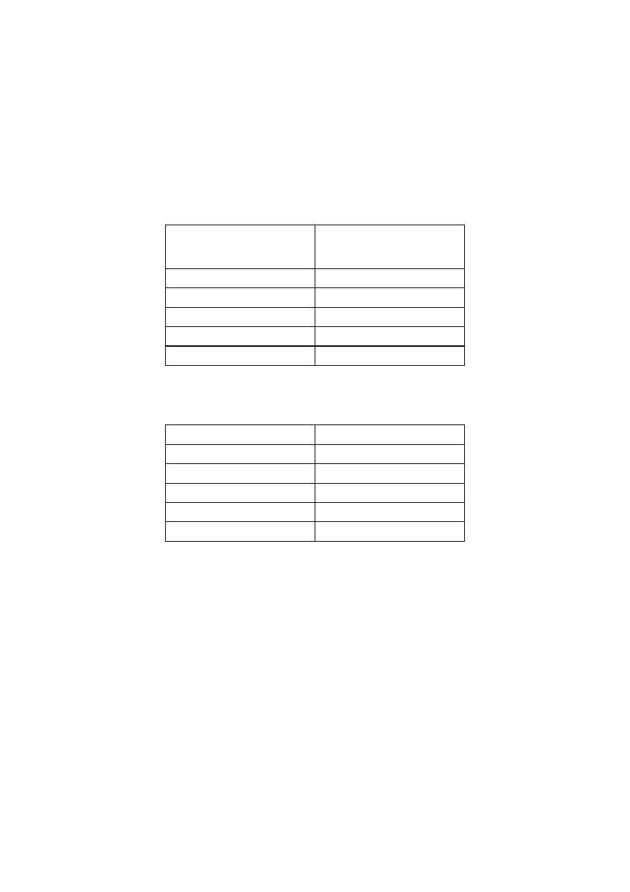
(2)P Actions shall be assigned to one of the load-duration classes given in Table 2.1 for
strength and stiffness calculations.
Table 2.1 – Load-duration classes
Load-duration class
Order of accumulated
duration of characteristic
load
Permanent
more than 10 years
Long-term
6 months – 10 years
Medium-term
1 week – 6 months
Short-term
less than one week
Instantaneous
NOTE: Examples of load-duration assignment are given in Table 2.2. Since climatic loads (snow, wind)
vary between countries, the assignment of load-duration classes may be specified in the National annex.
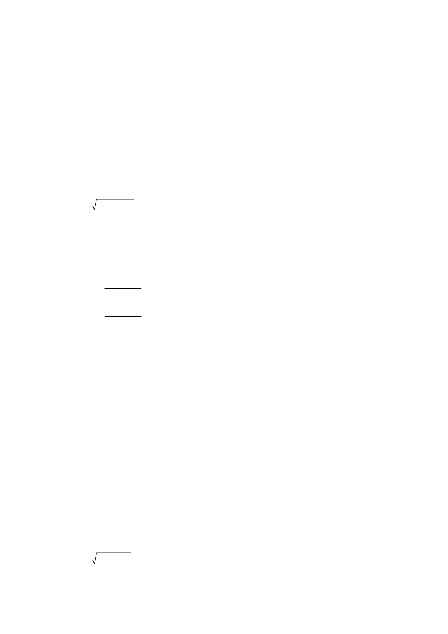
Table 2.2 – Examples of load-duration assignment
Load-duration class
Examples of loading
Permanent self-weight
Long-term storage
Medium-term
imposed floor load, snow
Short-term snow,
wind
Instantaneous wind,
accidental load
2.3.1.3 Service
classes
(1)P Structures shall be assigned to one of the service classes given below:
NOTE 1: The service class system is mainly aimed at assigning strength values and for
calculating deformations under defined environmental conditions.
NOTE 2: Information on the assignment of structures to service classes given in (2)P, (3)P and (4)P may
be given in the National annex.
(2)P Service class 1 is characterised by a moisture content in the materials corresponding to a
temperature of 20°C and the relative humidity of the surrounding air only exceeding 65 % for a
few weeks per year.
NOTE: In service class 1 the average moisture content in most softwoods will not exceed 12 %.
(3)P Service class 2 is characterised by a moisture content in the materials corresponding to a
temperature of 20°C and the relative humidity of the surrounding air only exceeding 85 % for a
few weeks per year.
prEN 1995-1-1:2003 (E)
23
NOTE: In service class 2 the average moisture content in most softwoods will not exceed 20 %.
(4)P Service class 3 is characterised by climatic conditions leading to higher moisture contents
than in service class 2.
2.3.2
Materials and product properties
2.3.2.1
Load-duration and moisture influences on strength
(1) Modification factors for the influence of load-duration and moisture content on strength, see
2.4.1, are given in 3.1.3.
(2) Where a connection is constituted of two timber elements having different time-dependent
behaviour, the calculation of the design load-carrying capacity should be made with the following
modification factor k
mod:
mod
mod,1
mod,2
=
k
k
k
(2.4)
where k
mod,1
and k
mod,2
are the modification factors for the two timber elements.
2.3.2.2
Load-duration and moisture influences on deformations
(1) The final mean value of modulus of elasticity, E
mean,fin
, shear modulus G
mean,fin
, and slip
modulus, K
ser,fin
, should be taken from the following expressions as:
(
)
mean
mean,fin
def
E
E
k
y
=
+
2
1
(2.5)
(
)
mean
mean,fin
def
G
G
k
y
=
+
2
1
(2.6)
(
)
ser
ser,fin
def
K
K
k
y
=
+
2
1
(2.7)
where:
E
mean
is the mean value of modulus of elasticity;
G
mean
is the mean value of shear modulus;
K
ser
is the slip modulus;
k
def
is a deformation factor taking into account the effect on the stiffness parameters of the
load and the moisture content in the structure;
y
2
is a factor for the quasi-permanent value of a variable action. For permanent actions,
y
2
should be replaced by 1,0.
NOTE 1: Values of k
def
are given in 3.1.4.
NOTE 2: Values of
y
2
are given in EN 1990:2002.
(2) Where a connection is constituted of timber elements with the same time-dependent
behaviour, the value of k
def
should be doubled.
(3) Where a connection is constituted of two wood-based elements having different time-
dependent behaviour, the calculation of the final deformation should be made with the following
deformation factor k
def
:
def
def,1
def,2
=
k
k
k
2
(2.8)
prEN 1995-1-1:2003 (E)
24
where k
def,1
and k
def,2
are the deformation factors for the two timber elements.
2.4
Verification by the partial factor method
2.4.1
Design value of material property
(1)P The design value X
d
of a strength property shall be calculated as:
k
d
mod
M
g
=
X
X
k
(2.9)
where:
X
k
is the characteristic value of a strength property;
g
M
is the partial factor for a material property;
k
mod
is a modification factor taking into account the effect of the duration of load and moisture
content.
NOTE 1: Values of k
mod
are given in 3.1.3.
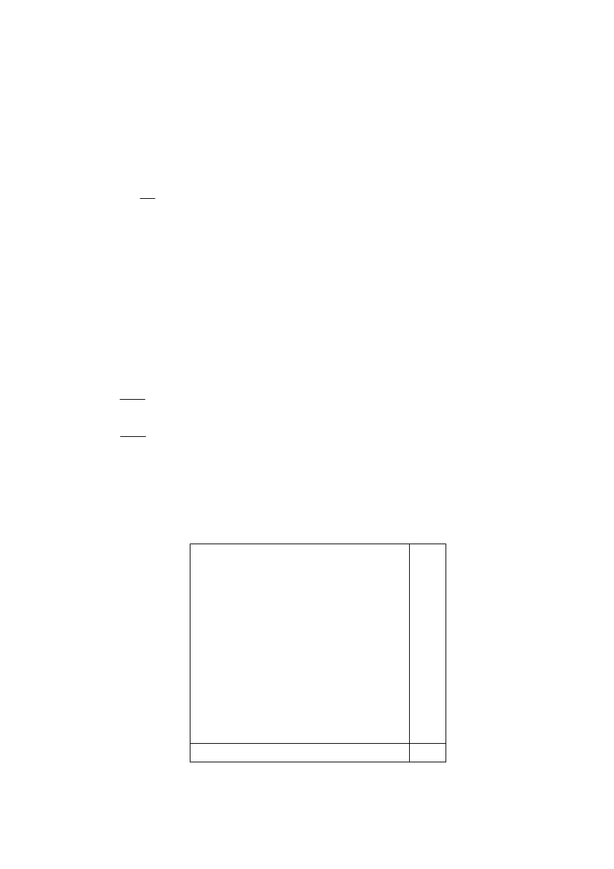
NOTE 2: The recommended partial factors for material properties (
g
M
) are given in Table 2.3. Information
on the National choice may be found in the National annex.
(2)P The design member stiffness property E
d
or G
d
shall be calculated as:
mean
d
M
g
=
E
E
(2.10)
mean
d
M
g
=
G
G
(2.11)
where:
E
mean
is the mean value of modulus of elasticity;
G
mean
is the mean value of shear modulus.
Table 2.3 – Recommended partial factors
g
M
for material properties and resistances
Fundamental combinations:
Solid
timber
1,3
Glued laminated timber
1,25
LVL, plywood, OSB,
1,2
Particleboards
1,3
Fibreboards,
hard
1,3
Fibreboards,
medium
1,3
Fibreboards,
MDF
1,3
Fibreboards,
soft
1,3
Connections
1,3
Punched metal plate fasteners
1,25
Accidental combinations
1,0

prEN 1995-1-1:2003 (E)
25
2.4.2
Design value of geometrical data
(1) Geometrical data for cross-sections and systems may be taken as nominal values from
product standards hEN or drawings for the execution.
(2) Design values of geometrical imperfections specified in this standard comprise the effects of
-
geometrical imperfections of members;
-
the effects of structural imperfections from fabrication and erection;
-
inhomogeneity of materials (e.g. due to knots).
2.4.3 Design
resistances
(1)P The design value R
d
of a resistance (load-carrying capacity) shall be calculated as:
k
d
mod
M
R
R
k
=
g
(2.12)
where:
R
k
is the characteristic value of load-carrying capacity;
g
M
is the partial factor for a material property,
k
mod
is a modification factor taking into account the effect of the duration of load and moisture
content.
NOTE 1: Values of k
mod
are given in 3.1.3.
NOTE 2: For partial factors, see 2.4.1.
2.4.4
Verification of equilibrium (EQU)
(1) The reliability format for the verification of static equilibrium given in Table A1.2 (A) in Annex
A1 of EN 1990:2002 applies, where appropriate, to the design of timber structures, e.g. for the
design of holding-down anchors or the verification of bearings subject to uplift from continuous
beams.

prEN 1995-1-1:2003 (E)
26
Section 3
Material properties
3.1 General
3.1.1
Strength and stiffness parameters
(1)P Strength and stiffness parameters shall be determined on the basis of tests for the types of
action effects to which the material will be subjected in the structure, or on the basis of
comparisons with similar timber species and grades or wood-based materials, or on well-
established relations between the different properties.
3.1.2 Stress-strain
relations
(1)P Since the characteristic values are determined on the assumption of a linear relation
between stress and strain until failure, the strength verification of individual members shall also
be based on such a linear relation.
(2) For members or parts of members subjected to compression, a non-linear relationship
(elastic-plastic) may be used.
3.1.3
Strength modification factors for service classes and load-duration classes
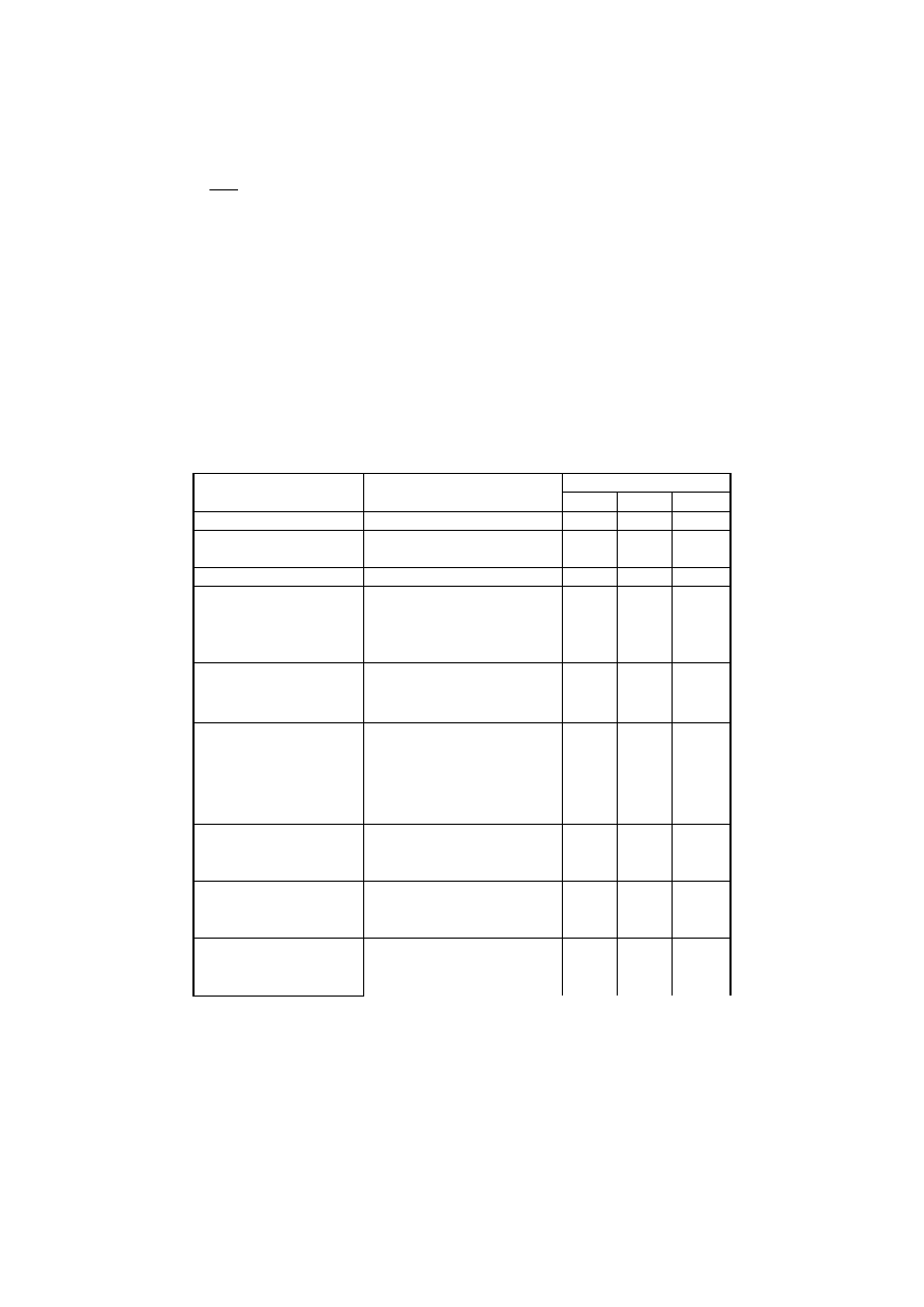
(1) The values of the modification factor k
mod
given in Table 3.1 should be used.
(2) If a load combination consists of actions belonging to different load-duration classes a value
of k
mod
should be chosen which corresponds to the action with the shortest duration, e.g. for a
combination of dead load and a short-term load, a value of k
mod
corresponding to the short-term
load should be used.
3.1.4
Deformation modification factors for service classes
(1) The values of the deformation factors k
def
given in Table 3.2 should be used.
3.2 Solid
timber
(1)P Timber members shall comply with EN 14081-1. Timber members with round cross-section
shall comply with EN 14544.
NOTE: Strength classes for timber are given in EN 338.
(2) The effect of member size on strength may be taken into account.
(3) For rectangular solid timber with a characteristic timber density
r
k
£
700 kg/m
3
, the reference
depth in bending or width (maximum cross-sectional dimension) in tension is 150 mm. For
depths in bending or widths in tension of solid timber less than 150 mm the characteristic values
for f
m,k
and f
t,0,k
may be increased by the factor k
h
, given by:
h
h
k
ìæ
ö
ïç
÷
ïè
ø
=
í
ï
ï
î
0,2
150
min
1,3
(3.1)
where h is the depth for bending members or width for tension members, in mm.

prEN 1995-1-1:2003 (E)
27
Table 3.1 – Values of k
mod
Load-duration class
Material Standard
Service
class
Permanen
t action
Long
term
action
Medium
term
action
Short
term
action
Instanta-
neous
action
1 0,60 0,70
0,80
0,90
1,10
2 0,60 0,70
0,80
0,90
1,10
Solid timber EN 14081-1
3 0,50 0,55
0,65
0,70
0,90
1 0,60 0,70
0,80
0,90
1,10
2 0,60 0,70
0,80
0,90
1,10
Glued
laminated
timber
EN 14080
3 0,50 0,55
0,65
0,70
0,90
1 0,60 0,70
0,80
0,90
1,10
2 0,60 0,70
0,80
0,90
1,10
LVL
EN 14374, EN 14279
3 0,50 0,55
0,65
0,70
0,90
EN 636
Part 1, Part 2, Part 3
1
0,60 0,70
0,80
0,90
1,10
Part 2, Part 3
2
0,60 0,70
0,80
0,90
1,10
Plywood
Part 3
3
0,50 0,55
0,65
0,70
0,90
EN
300
OSB/2
1
0,30
0,45
0,65
0,85
1,10
OSB/3, OSB/4
1
0,40
0,50
0,70
0,90
1,10
OSB
OSB/3, OSB/4
2
0,30
0,40
0,55
0,70
0,90
EN
312
Part 4, Part 5
1
0,30
0,45
0,65
0,85
1,10
Particle-
board
Part 5
2
0,20
0,30
0,45
0,60
0,80
Part 6, Part 7
1
0,40
0,50
0,70
0,90
1,10
Part 7
2
0,30
0,40
0,55
0,70
0,90
EN
622-2
HB.LA, HB.HLA 1 or
2
1 0,30 0,45
0,65
0,85
1,10
Fibreboard,
hard
HB.HLA1 or 2
2
0,20
0,30
0,45
0,60
0,80
EN
622-3
MBH.LA1 or 2
MBH.HLS1 or 2
1
1
0,20
0,20
0,40
0,40
0,60
0,60
0,80
0,80
1,10
1,10
Fibreboard,
medium
MBH.HLS1 or 2
2
–
–
–
0,45
0,80
EN
622-5
MDF.LA, MDF.HLS
1
0,20
0,40
0,60
0,80
1,10
Fibreboard,
MDF
MDF.HLS
2
–
–
–
0,45
0,80
(4) For timber which is installed at or near its fibre saturation point, and which is likely to dry out
under load, the values of k
def
, given in Table 3.2, should be increased by 1,0.
(5)P Finger joints shall comply with EN 385.
3.3
Glued laminated timber
(1)P Glued laminated timber members shall comply with EN 14080.
NOTE: In EN 1194 values of strength and stiffness properties are given for glued laminated timber
allocated to strength classes, see annex D (Informative).
(2) The effect of member size on strength may be taken into account.
(3) For rectangular glued laminated timber, the reference depth in bending or width in tension is
600 mm. For depths in bending or widths in tension of glued laminated timber less than 600 mm
prEN 1995-1-1:2003 (E)
28
the characteristic values for f
m,k
and f
t,0,k
may be increased by the factor k
h
, given by
h
h
k
ìæ
ö
ïç
÷
ïè
ø
=
í
ï
ï
î
0,1
600
min
1,1
(3.2)
where h is the depth for bending members or width for tensile members, in mm.
(4)P Large finger joints complying with the requirements of ENV 387 shall not be used for
products to be installed in service class 3, where the direction of grain changes at the joint.
(5)P The effect of member size on the tensile strength perpendicular to the grain shall be taken
into account.
Table 3.2 – Values of k
def
for timber and wood-based materials for quasi-permanent
actions.
Service class
Material Standard
1 2 3
Solid timber
EN 14081-1
0,60
0,80
2,00
Glued Laminated
timber
EN 14080
0,60
0,80
2,00
LVL
EN 14374, EN 14279
0,60
0,80
2,00
EN 636
Part
1
0,80 –
–
Part
2
0,80 1,00 –
Plywood
Part
3
0,80 1,00 2,50
EN 300
OSB/2
2,25
–
–
OSB
OSB/3,
OSB/4
1,50
2,25
–
EN 312
Part
4
2,25 –
–
Part
5
2,25 3,00 –
Part
6
1,50 –
–
Particleboard
Part
7
1,50 2,25 –
EN 622-2
HB.LA
2,25 –
–
Fibreboard, hard
HB.HLA1,
HB.HLA2
2,25 3,00 –
EN 622-3
MBH.LA1,
MBH.LA2
3,00 –
–
Fibreboard, medium
MBH.HLS1,
MBH.HLS2
3,00 4,00 –
EN 622-5
MDF.LA
2,25 –
–
Fibreboard, MDF
MDF.HLS
2,25 3,00 –
3.4
Laminated veneer lumber (LVL)
(1)P LVL structural members shall comply with EN 14374.
(2)P For rectangular LVL with the grain of all veneers running essentially in one direction, the
effect of member size on bending and tensile strength shall be taken into account.
(3) The reference depth in bending is 300 mm. For depths in bending not equal to 300 mm the

prEN 1995-1-1:2003 (E)
29
characteristic value for f
m,k
should be multiplied by the factor k
h
, given by
h
s
h
k
ìæ
ö
ïç
÷
ïè
ø
=
í
ï
ï
î
300
min
1,2
(3.3)
where:
h
is the depth of the member, in mm;
s is the size effect exponent, refer to 3.4(5)P.
(4) The reference length in tension is 3000 mm. For lengths in tension not equal to 3000 mm the
characteristic value for f
t,0,k
should be multiplied by the factor k
l
given by
s
k
ìæ
ö
ïç
÷
ïè
ø
=
í
ï
ï
î
l
/ 2
3000
min
1,1
l
(3.4)
where
l
is the length, in mm.
(5)P The size effect exponent
s
for LVL shall be taken as declared in accordance with
EN 14374.
(6)P Large finger joints complying with the requirements of ENV 387 shall not be used for
products to be installed in service class 3, where the direction of grain changes at the joint.
(7)P For LVL with the grain of all veneers running essentially in one direction, the effect of
member size on the tensile strength perpendicular to the grain shall be taken into account.
3.5 Wood-based
panels
(1)P Wood-based panels shall comply with EN 13986 and LVL used as panels shall comply with
EN 14279.
(2) The use of softboards according to EN 622-4 should be restricted to wind bracing and
should be designed by testing.
3.6 Adhesives
(1)P Adhesives for structural purposes shall produce joints of such strength and durability that
the integrity of the bond is maintained in the assigned service class throughout the expected life
of the structure.
(2) Adhesives which comply with Type I specification as defined in EN 301 may be used in all
service classes.
(3) Adhesives which comply with Type II specification as defined in EN 301 should only be used
in service classes 1 or 2 and not under prolonged exposure to temperatures in excess of 50°C.
3.7 Metal
fasteners
(1)P Metal fasteners shall comply with EN 14592 and metal connectors shall comply with
EN 14545.
prEN 1995-1-1:2003 (E)
30
Section 4
Durability
4.1
Resistance to biological organisms
(1)P Timber and wood-based materials shall either have adequate natural durability in
accordance with EN 350-2 for the particular hazard class (defined in EN 335-1, EN 335-2 and
EN 335-3), or be given a preservative treatment selected in accordance with EN 351-1 and
EN 460.
NOTE 1: Preservative treatment may affect the strength and stiffness properties.
NOTE 2: Rules for specification of preservation treatments are given in EN 350-2 and EN 335.
4.2
Resistance to corrosion
(1)P Metal fasteners and other structural connections shall, where necessary, either be
inherently corrosion-resistant or be protected against corrosion.
(2) Examples of minimum corrosion protection or material specifications for different service
classes (see 2.3.1.3) are given in Table 4.1.
Table 4.1 – Examples of minimum specifications for material protection against corrosion
for fasteners (related to ISO 2081)
Service Class
b
Fastener
1 2 3
Nails and screws with
d
£
4 mm
None Fe/Zn
12c
a
Fe/Zn
25c
a
Bolts, dowels, nails and screws with
d
> 4
mm
None None Fe/Zn
25c
a
Staples Fe/Zn
12c
a
Fe/Zn
12c
a
Stainless
steel
Punched metal plate fasteners and steel
plates up to 3 mm thickness
Fe/Zn 12c
a
Fe/Zn 12c
a
Stainless
steel
Steel plates from 3 mm up to 5 mm in
thickness
None
Fe/Zn 12c
a
Fe/Zn
25c
a
Steel plates over 5 mm thickness
None
None
Fe/Zn 25c
a
a
If hot dip zinc coating is used, Fe/Zn 12c should be replaced by Z275 and Fe/Zn 25c by
Z350 in accordance with EN 10147
b
For especially corrosive conditions consideration should be given to heavier hot dip
coatings or stainless steel.

prEN 1995-1-1:2003 (E)
31
Section 5
Basis of structural analysis
5.1 General
(1)P Calculations shall be performed using appropriate design models (supplemented, if
necessary, by tests) involving all relevant variables. The models shall be sufficiently precise to
predict the structural behaviour, commensurate with the standard of workmanship likely to be
achieved, and with the reliability of the information on which the design is based.
(2)P The global structural behaviour shall generally be assessed by calculating the action
effects with a linear material model (elastic behaviour).
(3) For structures able to redistribute the internal forces via connections of adequate ductility,
elastic-plastic methods may be used for the calculation of the internal forces in the members.
(4)P The model for the calculation of internal forces in the structure or in part of it shall take into
account the effects of deformations of the connections.
(5) In general, the influence of deformations in the connections should be taken into account
through their stiffness (rotational or translational for instance) or through prescribed slip values
as a function of the load level in the connection.
5.2 Members
(1)P The following shall be taken into account by the structural analysis:
-
deviations from straightness;
-
inhomogeneities of the material.
NOTE: Deviations from straightness and inhomogeneities are taken into account implicitly by the design
methods given in this standard.
(2)P Reductions in the cross-sectional area shall be taken into account in the member strength
verification.
(3) Reductions in the cross-sectional area may be ignored for the following cases:
-
nails and screws with a diameter of 6 mm or less, driven without pre-drilling;
-
holes in the compression area of members, if the holes are filled with a material of higher
stiffness than the wood.
(4) When assessing the effective cross-section at a joint with multiple fasteners, all holes within
a distance of half the minimum fastener spacing measured parallel to the grain from a given
cross-section should be considered as occurring at that cross-section.
5.3 Connections
(1)P The load-carrying-capacity of the connections shall be verified taking into account the forces
and the moments between the members determined by the global structural analysis, as defined
in 5.1.
(2)P The deformation of the connection shall be compatible with that assumed in the global
analysis.
(3)P The analysis of a connection shall take into account the behaviour of all the elements which
constitute the connection.

prEN 1995-1-1:2003 (E)
32
5.4 Assemblies
5.4.1 General
(1)P Structures shall be analysed using static models which consider in a realistic way the static
behaviour of the structure and of the supports.
(2) The analysis should be performed by frame models in accordance with 5.4.2 or by a
simplified analysis in accordance with 5.4.3 for trusses with punched metal plate fasteners.
(3) Second order analysis of plane frames or arches should be performed in accordance with
5.4.4.
5.4.2 Frame
structures
(1)P Frame structures shall be analysed such that the deformations of the members and joints,
the influence of support eccentricities and the stiffness of the supporting structure are taken into
account in the determination of the member forces and moments, see Figure 5.1 for definitions
of structure configurations and model elements
(2)P In a frame analysis, the system lines for all members shall lie within the member profile.
For the main members, e.g. the external members of a truss, the system lines shall coincide
with the member centre-line.
(3)P If the system lines for internal members do not coincide with the centre lines, the influence
of the eccentricity shall be taken into account in the strength verification of these members.
(4) Fictitious beam elements and spring elements may be used to model eccentric connections
or supports. The orientation of fictitious beam elements and the location of the spring elements
should coincide as closely as possible with the actual joint configuration.
(5) In a first order linear elastic analysis, instability of a member in compression may be
disregarded if it is taken into account by the strength verification of the member.
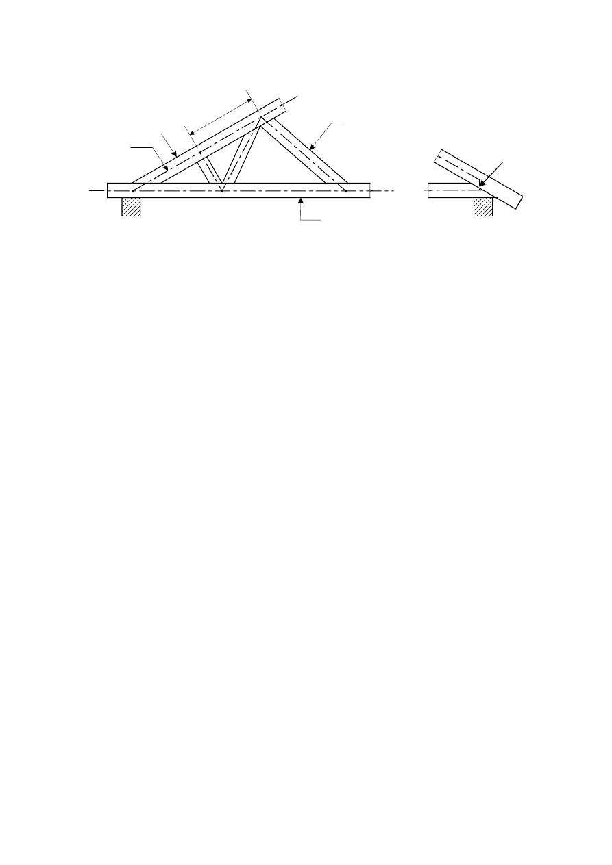
prEN 1995-1-1:2003 (E)
33
(3)
(1)
(2)
(4)
(5)
(6)
(4)
Key:
(1) System line
(2) Support
(3) Bay
(4) External member
(5) Internal member
(6) Fictitious beam element
Figure 5.1 – Examples of frame analysis model elements
(6) The frame analysis should be carried out using the appropriate values of member stiffness
defined in 2.2.2. Fictitious beam elements should be assumed to have a stiffness corresponding
to that of the actual connections.
(7) Connections may be assumed to be rotationally stiff, if their deformation has no significant
effect upon the distribution of member forces and moments. Otherwise, connections may be
generally assumed to be rotationally pinned.
(8) Translational slip at the joints may be disregarded for the strength verification unless it
significantly affects the distribution of internal forces and moments.
(9) Splice connections used in lattice structures may be modelled as rotationally stiff if the actual
rotation under load would have no significant effect upon member forces. This requirement is
fulfilled if one of the following conditions is satisfied:
-
The splice connection has a load-carrying capacity which corresponds to at least 1,5 times
the combination of applied force and moment
-
The splice connection has a load-carrying capacity which corresponds to at least the
combination of applied force and moment, provided that the timber members are not subject
to bending stresses which are greater than 0,3 times the member bending strength, and the
assembly would be stable if all such connections acted as pins.
5.4.3
Simplified analysis of trusses with punched metal plate fasteners
(1) A simplified analysis of fully triangulated trusses should comply with the following conditions:
-
there are no re-entrant angles in the external profile;
-
the bearing width is situated within the length
a
1
, and the distance a
2
in Figure 5.2 is not
greater than a
1
/3 or 100 mm, whichever is the greater;
-
the truss height is greater than 0,15 times the span and 10 times the maximum external
member depth.
.
(2) The axial forces in the members should be determined on the basis that every node is pin-
jointed.
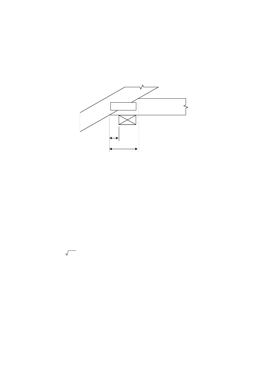
prEN 1995-1-1:2003 (E)
34
(3) The bending moments in single-bay members should be determined on the basis that the
end nodes are pin-jointed. Bending moments in members that are continuous over several bays
should be determined on the basis that the member is a beam with a simple support at each
node. The effect of deflection at the nodes and partial fixity at the connections should be taken
into account by a reduction of 10 % of the moments at the inner supports of the member. The
inner support moments should be used to calculate the span bending moments.
a
1
a
2
Figure 5.2 – Geometry of support
5.4.4
Plane frames and arches
(1)P The requirements of 5.2 apply. The effects of induced deflection on internal forces and
moments shall be taken into account.
(2) The effects of induced deflection on internal forces and moments may be taken into account
by carrying out a second order linear analysis with the following assumptions:
-
the imperfect shape of the structure should be assumed to correspond to an initial
deformation which is found by applying an angle
f
of inclination to the structure or relevant
parts, together with an initial sinusoidal curvature between the nodes of the structure
corresponding to a maximum eccentricity e.
-
the value of
f
in radians should as a minimum be taken as
h
h
h
f
f
=
£
=
>
0,005
for
5 m
0,005 5 /
for
5 m
(5.1)
where h is the height of the structure or the length of the member, in m.
-
the value of
e
should as a minimum be taken as:
e
=
l
0,0025
(5.2)
Examples of assumed initial deviations in the geometry and the definition of
l
are given in
Figure 5.3.
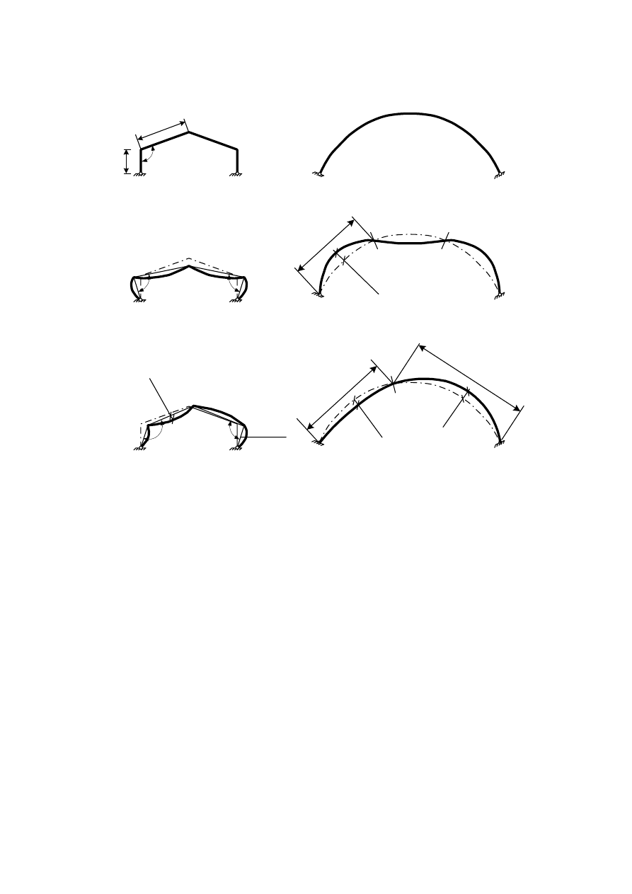
prEN 1995-1-1:2003 (E)
35
a)
b)
c)
0,0025
l
0,0025 h
0,0025
l
1
l
2
l
1
0,0025
l
1
a + f
a - f
a - f
a - f
a
h
l
l
2
l
1
0,0025
l
2
l
1
Figure 5.3 – Examples of assumed initial deviations in the geometry for a frame (a),
corresponding to a symmetrical load (b) and non-symmetrical load (c)
prEN 1995-1-1:2003 (E)
36
Section 6
Ultimate limit states
6.1
Design of cross-sections subjected to stress in one principal direction
6.1.1 General
(1) Clause 6.1 applies to straight solid timber, glued laminated timber or wood-based structural
products of constant cross-section, whose grain runs essentially parallel to the length of the
member. The member is assumed to be subjected to stresses in the direction of only one of its
principal axes (see Figure 6.1).
(1)
y
y
z
z
x
Key:
(1) direction of grain
Figure 6.1 – Member Axes
6.1.2
Tension parallel to the grain
(1)P The following expression shall be satisfied:
f
s
£
t,0,d
t,0,d
(6.1)
where:
s
t,0,d
is the design tensile stress along the grain;
f
t,0,d
is the design tensile strength along the grain.
6.1.3
Tension perpendicular to the grain
(1)P The effect of member size shall be taken into account.
6.1.4
Compression parallel to the grain
(1)P The following expression shall be satisfied:
c,0,d
c,0,d
f
s
£
(6.2)
where:
s
c,0,d
is the design compressive stress along the grain;
f
c,0,d
is the design compressive strength along the grain.
NOTE: Rules for the instability of members are given in 6.3.
6.1.5
Compression perpendicular to the grain
(1)P The following expression shall be satisfied:
c,90,d
c,90 c,90,d
k
f
s
£
(6.3)
prEN 1995-1-1:2003 (E)
37
where:
s
c,90,d
is the design compressive stress in the contact area perpendicular to the grain;
f
c,90,d
is the design compressive strength perpendicular to the grain;
k
c,90
is a factor taking into account the load configuration, possibility of splitting and degree
of compressive deformation.
(2) The value of
k
c,90
should be taken as 1,0, unless the member arrangements in the following
paragraphs apply. In these cases the higher value of
k
c,90
specified may be taken, up to a
limiting value of
k
c,90
= 4,0.
NOTE: When a higher value of k
c,90
is used, and contact extends over the full member width b, the
resulting compressive deformation at the ultimate limit state will be approximately 10 % of the member
depth.
(3) For a beam member resting on supports (see Figure 6.2), the factor
k
c,90
should be
calculated from the following expressions:
-
When the distance from the edge of a support to the end of a beam
a
, ≤
h
/3:
c,90
h
k
æ
öæ
ö
=
-
+
ç
֍
÷
è
øè
ø
l
l
2,38
1
250
12
(6.4)
-
At internal supports:
,
h
k
æ
öæ
ö
=
-
+
ç
֍
÷
è
øè
ø
l
l
c,90
2 38
1
250
6
(6.5)
where:
l
is the contact length in mm;
h
is member depth in mm.
h
a
l
l
b
Figure 6.2 – Beam on supports
(4) For a member with a depth
h
£
2,5
b
where a concentrated force with contact over the full
width
b
of the member is applied to one face directly over a continuous or discrete support on
the opposite face, see Figure 6.3, the factor
k
c,90
is given by:
ef
æ
ö
æ
ö
=
-
ç
÷
ç
÷
è
øè
ø
l
l
l
0,5
c,90
2,38
250
k
(6.6)
where:
l
ef
is the effective length of distribution, in mm, see (5) below;
l is the contact length, see Figure 6.3, in mm.
prEN 1995-1-1:2003 (E)
38
l
l
1
1:3
l
ef
h
£ 2,5b
l
l
1
1:3
l
ef
h
£ 2,5b
a
³ a/2
³l
1
/4
³l
1
/4
(a)
(b)
b
h
l
ef
l
s
l
l
1
h
£ 2,5b
1:3
1:3
(c)
a
b
h
Figure 6.3 – Determination of effective lengths for a member with h/b
£ 2,5, (a) and (b)
continuous support, (c) discrete supports
(5) The effective length of distribution
l
ef
should be determined from a stress dispersal line with
a vertical inclination of 1:3 over the depth h, but curtailed by a distance of a/2 from any end, or a
distance of
l
1
/4 from any adjacent compressed area, see Figure 6.3a and b.
For the particular positions of forces below, the effective length is given by:
- for loads adjacent to the end of the member, see Figure 6.3a
ef
h
= +
3
l
l
(6.7)
- when the distance from the edge of a concentrated load to the end of the member a,
h
³
2
3
,see Figure 6.3b
ef
h
= +
2
3
l
l
(6.8)
where h is the depth of the member or 40 mm, whichever is the largest.
For members on discrete supports, provided that a
³ h and
1
2 ,
³ h
l
see Figure 6.3c, the
effective length should be calculated as:

prEN 1995-1-1:2003 (E)
39
ef
s
h
æ
ö
=
+
+
ç
÷
è
ø
2
0,5
3
l
l l
(6.9)
where h is the depth of the member or 40 mm, whichever is the largest.
(6) For a member with a depth h > 2,5b loaded with a concentrated compressive force on two
opposite sides as shown in Figure 6.4b, or with a concentrated compressive force on one side
and a continuous support on the other, see Figure 6.4a, the factor k
c,90
should be calculated
according to expression (6.10), provided that the following conditions are fulfilled:
- the applied compressive force occurs over the full member width b;
- the contact length l is less than the greater of h or 100 mm:
ef
c,90
k
=
l
l
(6.10)
where:
l
is the contact length according to Figure 6.4;
l
ef
is the effective length of distribution according to Figure 6.4.
The effective length of distribution should not extend by more than
l beyond either edge of the
contact length.
(7) For members whose depth varies linearly over the support (e.g.bottom chords of trusses at
the heel joint), the depth h should be taken as the member depth at the centreline of the
support, and the effective length
l
ef
should be taken as equal to the contact length
l.
prEN 1995-1-1:2003 (E)
40
Figure 6.4 – Determination of effective lengths for a member with h/b > 2,5 on (a) a
continuous support, (b) discrete supports

prEN 1995-1-1:2003 (E)
41
6.1.6 Bending
(1)P The following expressions shall be satisfied:
m,y,d
m,z,d
m
m,y,d
m,z,d
k
f
f
s
s
+
£
1
(6.11)
m,y,d
m,z,d
m
m,y,d
m,z,d
k
f
f
s
s
+
£
1
(6.12)
where:
s
m,y,d
and
s
m,z,d
are the design bending stresses about the principal axes as shown in Figure
6.1;
f
m,y,d
and f
m,z,d
are the corresponding design bending strengths.
NOTE: The factor k
m
makes allowance for re-distribution of stresses and the effect of inhomogeneities of
the material in a cross-section.
(2) The value of the factor k
m
should be taken as follows:
For solid timber, glued laminated timber and LVL:
for rectangular sections: k
m
= 0,7
for other cross-sections: k
m
= 1,0
For other wood-based structural products, for all cross-sections: k
m
= 1,0
(3)P A check shall also be made of the instability condition (see 6.3).
6.1.7 Shear
(1)P For shear with a stress component parallel to the grain, see Figure 6.5(a), as well as for
shear with both stress components perpendicular to the grain, see Figure 6.5(b), the following
expression shall be satisfied:
t £
d
v,d
f
(6.13)
where:
t
d
is the design shear stress;
f
v,d
is the design shear strength for the actual condition.
NOTE: The shear strength for rolling shear is approximately equal to twice the tension strength
perpendicular to grain.
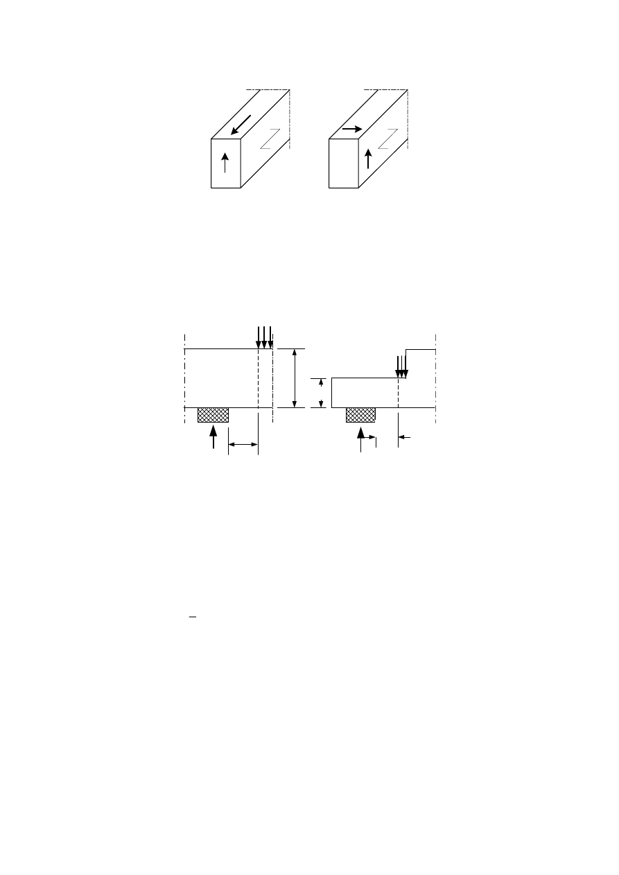
prEN 1995-1-1:2003 (E)
42
(a)
(b)
Figure 6.5 – (a) Member with a shear stress component parallel to the grain (b) Member
with both stress components perpendicular to the grain (rolling shear)
(2) At supports, the contribution to the total shear force of a concentrated load F acting on the
top side of the beam and within a distance h or h
ef
from the edge of the support may be
disregarded (see Figure 6.6). For beams with a notch at the support this reduction in the shear
force applies only when the notch is on the opposite side to the support.
< h
h
h
ef
< h
ef
F
F
Figure 6.6 – Conditions at a support, for which the concentrated force F may be
disregarded in the calculation of the shear force
6.1.8 Torsion
(1)P The following expression shall be satisfied:
tor,d
shape
v,d
k
f
t
£
(6.14)
with
shape
h
k
b
ì
ïï ì
= í
ï
í
ï
ï
ï
î
î
1,2
for a circular cross section
1+0,15
min
for a rectangular cross section
2,0
(6.15)
where:
t
tor,d
is the design torsional stress;
f
v,d
is the design shear strength;
k
shape
is a factor depending on the shape of the cross-section;
h
is the larger cross-sectional dimension;
b
is the smaller cross-sectional dimension.
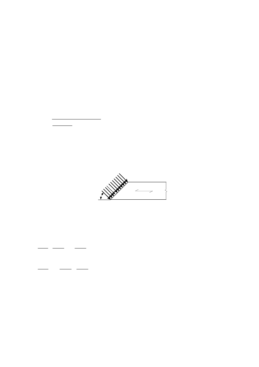
prEN 1995-1-1:2003 (E)
43
6.2
Design of cross-sections subjected to combined stresses
6.2.1 General
(1)P Clause 6.2 applies to straight solid timber, glued laminated timber or wood-based structural
products of constant cross-section, whose grain runs essentially parallel to the length of the
member. The member is assumed to be subjected to stresses from combined actions or to
stresses acting in two or three of its principal axes.
6.2.2
Compression stresses at an angle to the grain
(1)P Interaction of compressive stresses in two or more directions shall be taken into account.
(2) The compressive stresses at an angle
a to the grain, (see Figure 6.7), should satisfy the
following expression:
c,0,d
c,α,d
c,0,d
c,90
c,90,d
f
f
k
f
s
a
a
£
+
2
2
sin
cos
(6.16)
where:
s
c, ,d
is the compressive stress at an angle
a
to the grain;
k
c,90
is a factor given in 6.1.5 taking into account the effect of any of stresses perpendicular
to the grain.
a
s
c,
a
Figure 6.7 – Compressive stresses at an angle to the grain
6.2.3
Combined bending and axial tension
(1)P The following expressions shall be satisfied:
m,y,d
t,0,d
m,z,d
m
t,0,d
m,y,d
m,z,d
k
f
f
f
s
s
s
+
+
£
1
(6.17)
m,y,d
t,0,d
m,z,d
m
t,0,d
m,y,d
m,z,d
k
f
f
f
s
s
s
+
+
£
1
(6.18)
(2) The values of k
m
given in 6.1.6 apply.
6.2.4
Combined bending and axial compression
(1)P The following expressions shall be satisfied:

prEN 1995-1-1:2003 (E)
44
m,y,d
c,0,d
m,z,d
m
c,0,d
m,y,d
m,z,d
k
f
f
f
s
s
s
æ
ö
ç
÷ +
+
£
ç
÷
ç
÷
è
ø
2
1
(6.19)
m,y,d
c,0,d
m,z,d
m
c,0,d
m,y,d
m,z,d
k
f
f
f
s
s
s
æ
ö
ç
÷ +
+
£
ç
÷
ç
÷
è
ø
2
1
(6.20)
(2)P The values of k
m
given in 6.1.6 apply.
NOTE: To check the instability condition, a method is given in 6.3.
6.3
Stability of members
6.3.1 General
(1)P The bending stresses due to initial curvature, eccentricities and induced deflection shall be
taken into account, in addition to those due to any lateral load.
(2)P Column stability and lateral torsional stability shall be verified using the characteristic
properties, e.g. E
0,05
(3) The stability of columns subjected to either compression or combined compression and
bending should be verified in accordance with 6.3.2.
(4) The lateral torsional stability of beams subjected to either bending or combined bending and
compression should be verified in accordance with 6.3.3.
6.3.2
Columns subjected to either compression or combined compression and bending
(1) The relative slenderness ratios should be taken as:
y
c,0,k
rel,y
f
E
l
l
=
p
0,05
(6.21)
and
c,0,k
z
rel,z
f
E
l
l
=
p
0,05
(6.22)
where:
l
y
and
l
rel,y
are slenderness ratios corresponding to bending about the y-axis (deflection in the
z
-direction);
l
z
and
l
rel,z
are slenderness ratios corresponding to bending about the z-axis (deflection in the
y
-direction);
E
0,05
is the fifth percentile value of the modulus of elasticity parallel to the grain.
(2) Where both
l
rel,z
£ 0,3 and l
rel,y
£ 0,3 the stresses should satisfy the expressions (6.19) and
(6.20) in 6.2.4.
(3) In all other cases the stresses, which will be increased due to deflection, should satisfy the
following expressions:
prEN 1995-1-1:2003 (E)
45
m,y,d
c,0,d
m,z,d
m
c,y
c,0,d
m,y,d
m,z,d
k
f
f
f
k
s
s
s
+
+
£
1
(6.23)
m,y,d
c,0,d
m,z,d
m
c,z
c,0,d
m,y,d
m,z,d
k
f
f
f
k
s
s
s
+
+
£
1
(6.24)
where the symbols are defined as follows:
c,y
y
y
rel,y
k
k
k
l
=
+
2
2
1
-
(6.25)
c,z
z
z
rel,z
k
k
k
l
=
+
2
2
1
-
(6.26)
(
)
(
)
y
c
rel,y
rel,y
k
b l
l
=
+
+
2
0,5 1
- 0,3
(6.27)
(
)
(
)
z
c
rel,z
rel,z
k
b l
l
=
+
+
2
0,5 1
- 0,3
(6.28)
where:
b
c
is a factor for members within the straightness limits defined in Section 10:
c
b
ì
= í
î
0,2 for
solid
timber
0,1
for glued laminated timber and LVL
(6.29)
k
m
as given in 6.1.6.
6.3.3
Beams subjected to either bending or combined bending and compression
(1)P Lateral torsional stability shall be verified both in the case where only a moment M
y
exists
about the strong axis
y
and where a combination of moment M
y
and compressive force N
c
exists.
(2) The relative slenderness for bending should be taken as:
m,k
rel,m
m,crit
f
l
s
=
(6.30)
where
s
m,crit
is the critical bending stress calculated according to the classical theory of stability,
using 5-percentile stiffness values.
The critical bending stress should be taken as:
z
tor
y,crit
m,crit
y
ef
y
E
I G
I
M
W
W
p
s
=
=
l
0,05
0,05
(6.31)
where:
E
0,05
is the fifth percentile value of modulus of elasticity parallel to grain;
G
0,05
is the fifth percentile value of shear modulus parallel to grain;
I
z
is the second moment of area about the weak axis
z.
I
tor
is the torsional moment of inertia;
prEN 1995-1-1:2003 (E)
46
l
ef
is the effective length of the beam, depending on the support conditions and the load
configuration, acccording to Table 6.1;
W
y
is the section modulus about the strong axis
y.
For softwood with solid rectangular cross-section,
s
m,crit
should be taken as:
m,crit
ef
b
E
h
s
=
l
2
0,05
0,78
(6.32)
where:
b
is the width of the beam;
h
is the depth of the beam.
(3) In the case where only a moment
M
y
exists about the strong axis y, the stresses should
satisfy the following expression:
m,d
crit
m,d
k
f
s
£
(6.33)
where:
σ
m,d
is the design bending stress;
f
m,d
is the design bending strength;
k
crit
is a factor which takes into account the reduced bending strength due to lateral
buckling.
Table 6.1 – Effective length as a ratio of the span
Beam type
Loading type
l
ef
/
l
a
Simply supported
Constant moment
Uniformly distributed load
Concentrated force at the middle of the
span
1,0
0,9
0,8
Cantilever
Uniformly distributed load
Concentrated force at the free end
0,5
0,8
a
The ratio between the effective length
l
ef
and the span
l is valid for a
beam with torsionally restrained supports and loaded at the centre of
gravity. If the load is applied at the compression edge of the beam,
l
ef
should be increased by 2h and may be decreased by 0,5h for a load at
the tension edge of the beam.
(4) For beams with an initial lateral deviation from straightness within the limits defined in
Section 10,
k
crit
may be determined from expression (6.34)
rel,m
crit
rel,m
rel,m
rel,m
rel,m
k
l
l
l
l
l
ì
ï
£
ï
ï
ï
=
<
£
í
ï
ï
ï
<
ïî
2
1
for 0,75
1,56 - 0,75
for
0,75
1,4
1
for 1,4
(6.34)
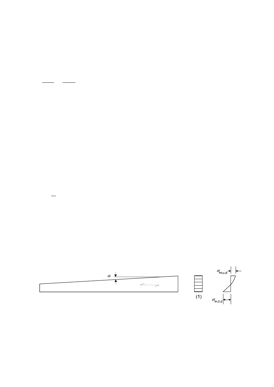
prEN 1995-1-1:2003 (E)
47
(5) The factor k
crit
may be taken as 1,0 for a beam where lateral displacement of its compressive
edge is prevented throughout its length and where torsional rotation is prevented at its supports.
(6) In the case where a combination of moment M
y
about the strong axis
y
and compressive
force
N
c
exists, the stresses should satisfy the following expression:
s
s
æ
ö
+
£
ç
÷
ç
÷
è
ø
2
m,d
c,d
crit m,d
c,z c,0,d
1
k f
k f
(6.35)
where:
σ
m,d
is the design bending stress;
σ
c,d
is the design compressive stress;
f
c,0,d
is the design compressive strength parallel to grain;
k
c,z
is given by expression (6.26).
6.4
Design of cross-sections in members with varying cross-section or curved shape
6.4.1 General
(1)P The effects of combined axial force and bending moment shall be taken into account.
(2) The relevant parts of 6.2 and 6.3 should be verified.
(3) The stress at a cross-section from an axial force may be calculated from
N
N
A
s =
(6.36)
where:
s
N
is the axial stress;
N
is the axial force;
A
is the area of the cross-section.
6.4.2
Single tapered beams
(1)P The influence of the taper on the bending stresses parallel to the surface shall be taken
into account.
Key:
(1) cross-section
Figure 6.8 – Single tapered beam
(2) The design bending stresses, σ
m,α,d
and σ
m,0,d
(see Figure 6.8) may be taken as:
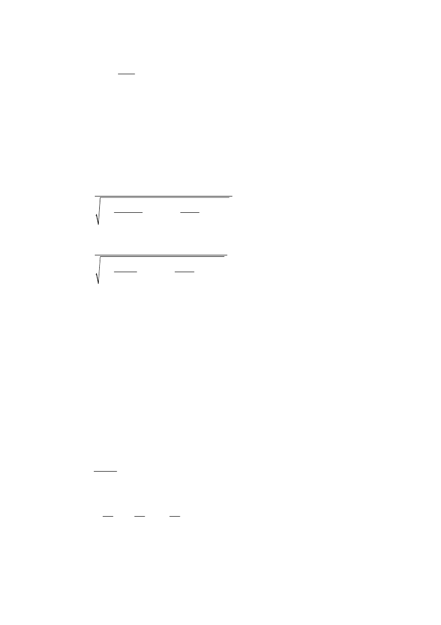
prEN 1995-1-1:2003 (E)
48
d
m, ,d
m, ,d
M
b h
a
s
s
=
=
0
2
6
(6.37)
At the outermost fibre of the tapered edge, the stresses should satisfy the following expression:
m,α,d
m,α
m,d
k
f
s
£
(6.38)
where:
σ
m,α,d
is the design bending stress at an angle to grain;
f
m,d
is the design bending strength;
k
m,
a
should be calculated as:
For tensile stresses parallel to the tapered edge:
m,α
m,d
m,d
v,d
t,90,d
k
f
f
f
f
a
a
=
æ
ö
æ
ö
+
+
ç
÷
ç
÷
ç
÷
ç
÷
è
ø
è
ø
2
2
2
1
1
tan
tan
0,75
(6.39)
For compressive stresses parallel to the tapered edge:
m,α
m,d
m,d
v,d
c,90,d
k
f
f
f
f
a
a
=
æ
ö
æ
ö
+
+
ç
÷
ç
÷
ç
÷
ç
÷
è
ø
è
ø
2
2
2
1
1
tan
tan
1,5
(6.40)
6.4.3
Double tapered, curved and pitched cambered beams
(1) This clause applies only to glued laminated timber and LVL.
(2) The requirements of 6.4.2 apply to the parts of the beam which have a single taper.
(3) In the apex zone (see Figure 6.9), the bending stresses should satisfy the following
expression:
m,d
r m,d
k f
s
£
(6.41)
where k
r
takes into account the strength reduction due to bending of the laminates during
production.
NOTE: In curved and and pitched cambered beams the apex zone extends over the curved part of the
beam
(4) The apex bending stress should be calculated as follows:
ap,d
m,d
ap
M
k
b h
s
=
l
2
6
(6.42)
with:
2
3
ap
ap
ap
1
2
3
4
h
h
h
k
k
k
k
k
r
r
r
æ
ö
æ
ö
æ
ö
= +
+
+
ç
÷
ç
÷
ç
÷
è
ø
è
ø
è
ø
l
(6.43)
ap
ap
k
a
a
= +
+
2
1
1
1,4 tan
5,4 tan
(6.44)

prEN 1995-1-1:2003 (E)
49
ap
k
a
=
2
0,35 - 8 tan
(6.45)
ap
ap
k
a
a
=
+
2
3
0,6
8,3 tan
- 7,8 tan
(6.46)
ap
k
a
=
2
4
6 tan
(6.47)
in
ap
r
r
h
=
+ 0,5
(6.48)
where:
M
ap,d
is the design moment at the apex;
h
ap
is the depth of the beam at the apex, see Figure 6.9;
b
is the width of the beam;
r
in
is the inner radius, see Figure 6.9;
a
ap
is the angle of the taper in the middle of the apex zone, see Figure 6.9.
(5) For double tapered beams k
r
= 1,0. For curved and pitched cambered beams
k
r
should be
taken as:
r
in
r
t
k
r
r
t
t
ì
³
ïï
= í
ï
+
<
ïî
in
in
1
for 240
0,76 0,001
for 240
(6.49)
where
r
in
is the inner radius, see Figure 6.9;
t
is the lamination thickness.
(6) In the apex zone the greatest tensile stress perpendicular to the grain,
s
t,90,d
, should satisfy
the following expression:
t,90,d
dis
vol t,90,d
k
k
f
s
£
(6.50)
with
vol
k
V
V
ì
ï
= íæ ö
ïç
÷
è
ø
î
0,2
0
1,0
for solid timber
for glued laminated timber and LVL with
all veneers parallel to the beam axis
(6.51)
ì
= í
î
dis
1,4
for double tapered and curved beams
1,7
for pitched cambered beams
k
(6.52)
where:
k
dis
is a factor which takes into account the effect of the stress distribution in the apex zone;
k
vol
is a volume factor;
f
t,90,d
is the design tensile strength perpendicular to the grain;
V
0
is the reference volume of 0,01m³;
V
is the stressed volume of the apex zone, in m
3
, (see Figure 6.9) and should not be
taken greater than 2V
b
/3, where V
b
is the total volume of the beam.
(7) For combined tension perpendicular to grain and shear the following expression shall be
satisfied:

prEN 1995-1-1:2003 (E)
50
t,90,d
d
dis
vol
v,d
t,90,d
k k
f
f
s
t
+
£
1
(6.53)
where:
t
d
is the design shear stress;
f
v,d
is the design shear strength;
σ
t,90,d
is the design tensile stress perpendicular to grain;
k
dis
and
k
vol
are given in (6).
(8) The greatest tensile stress perpendicular to the grain due to the bending moment should be
calculated as follows:
ap,d
p
t,90,d
ap
M
k
b h
s
=
2
6
(6.54)
or, as an alternative to expression (6.54), as
ap,d
d
t,90,d
ap
M
p
k
b
b h
s
=
-
p
2
6
0,6
(6.55)
where:
p
d
is the uniformly distributed load acting on the top of the beam over the apex area;
b
is the width of the beam;
M
ap,d
is the design moment at apex resulting in tensile stresses parallel to the inner curved
edge;
with:
ap
ap
p
h
h
k
k
k
k
r
r
æ
ö
æ
ö
=
+
+
ç
÷
ç
÷
è
ø
è
ø
2
5
6
7
(6.56)
ap
k
a
=
5
0,2 tan
(6.57)
ap
ap
k
a
a
=
+
2
6
0,25 - 1,5 tan
2,6 tan
(6.58)
ap
ap
k
a
a
=
2
7
2,1 tan
- 4 tan
(6.59)
Note: The recommended expression is (6.54).Information on the national choice between expressions
(6.54) and (6.55) may be found in the National annex.
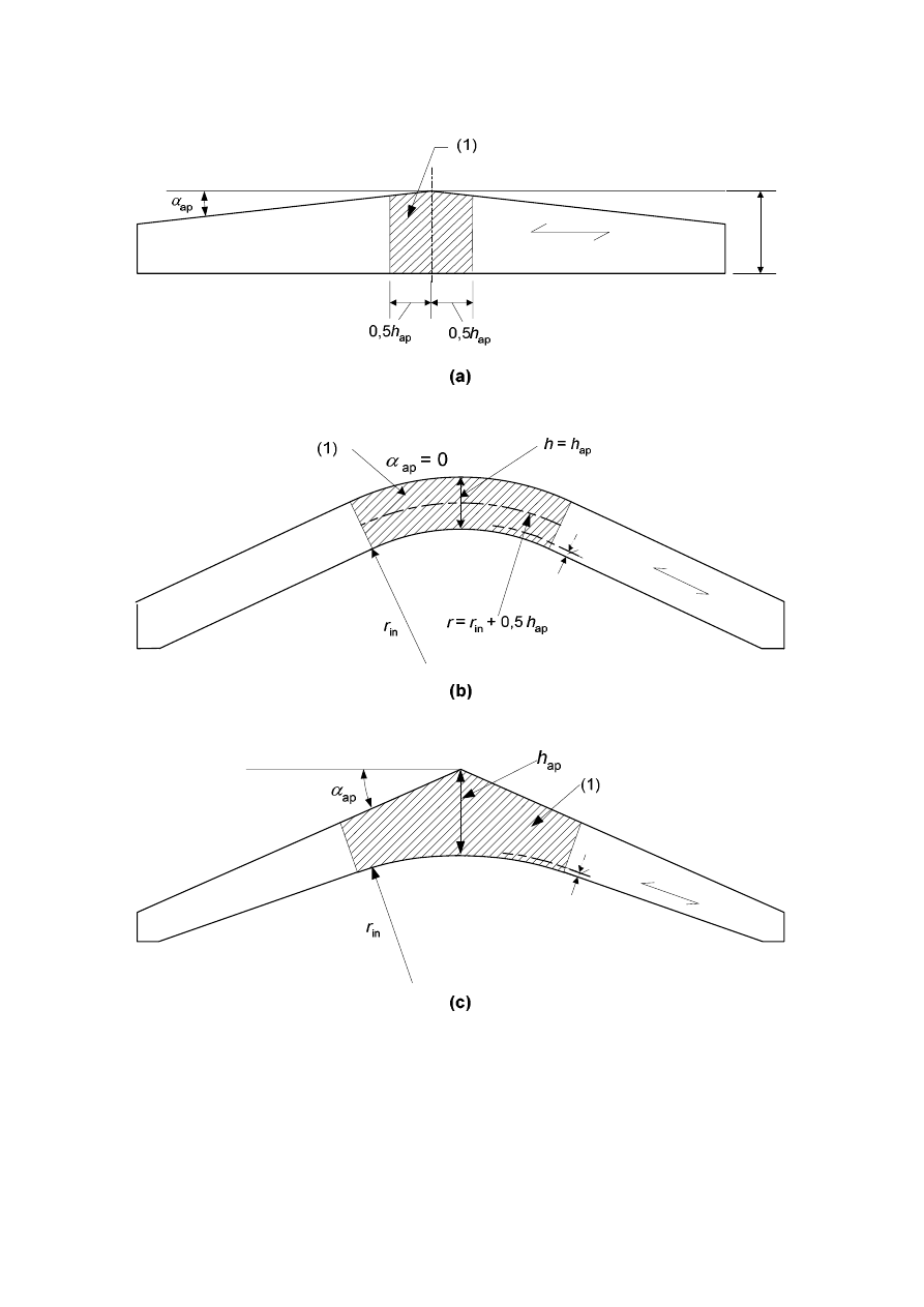
prEN 1995-1-1:2003 (E)
51
t
t
h
ap
Key:
(1) Apex Zone
NOTE: In curved and pitched cambered beams the apex zone extends over the curved parts of the beam.
Figure 6.9 – Double tapered (a), curved (b) and pitched cambered (c) beams with the fibre
direction parallel to the lower edge of the beam
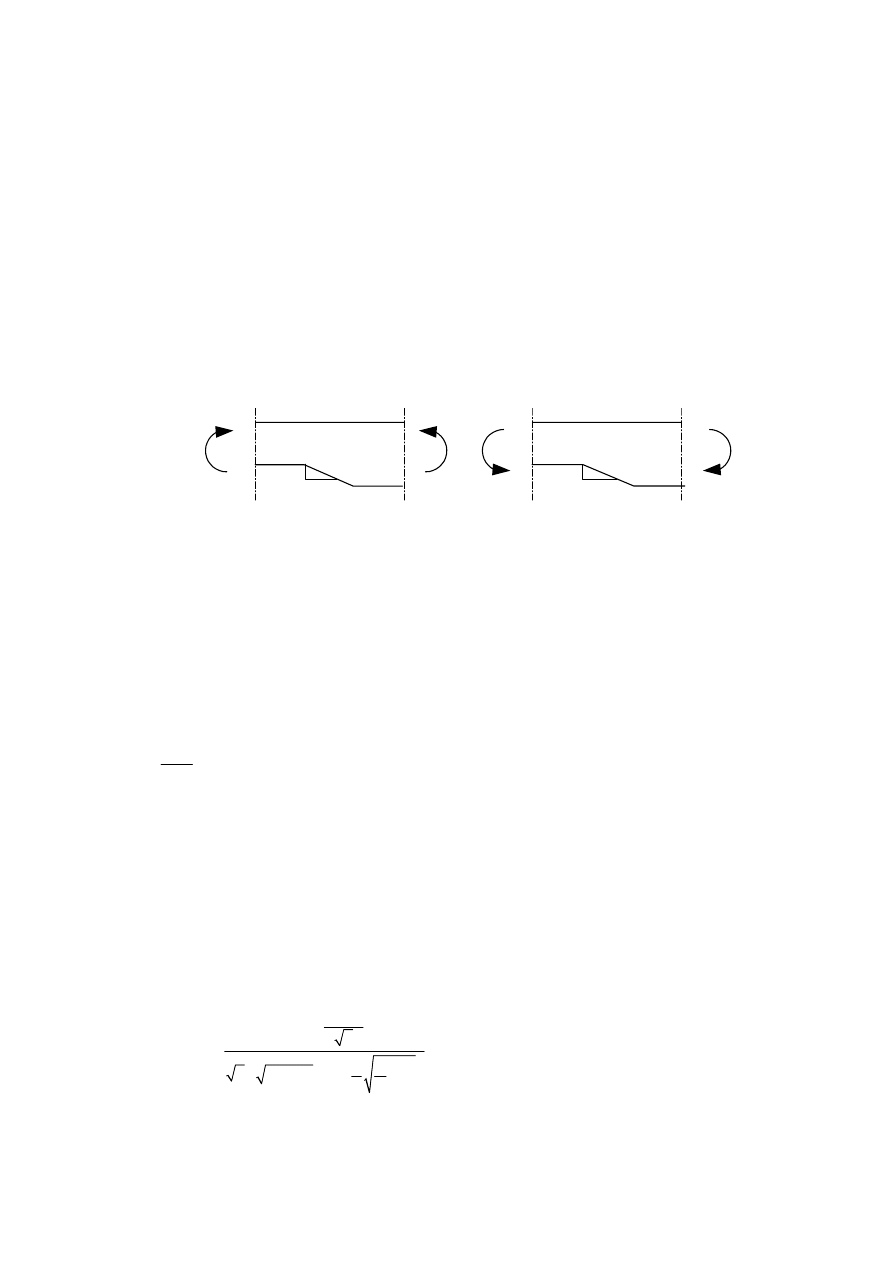
prEN 1995-1-1:2003 (E)
52
6.5 Notched
members
6.5.1 General
(1)P The effects of stress concentrations at the notch shall be taken into account in the strength
verification of members.
(2) The effect of stress concentrations may be disregarded in the following cases:
-
tension or compression parallel to the grain;
-
bending with tensile stresses at the notch if the taper is not steeper than 1:
i
= 1:10, that is
i
³
10, see Figure 6.10a;
-
bending with compressive stresses at the notch, see Figure 6.10b.
1
i
M
i
1
M
M
M
a) b)
Figure 6.10 – Bending at a notch: a) with tensile stresses at the notch,
b) with compressive stresses at the notch
6.5.2
Beams with a notch at the support
(1) For beams with rectangular cross-sections and where grain runs essentially parallel to the
length of the member, the shear stresses at the notched support should be calculated using the
effective (reduced) depth
h
ef
(see Figure 6.11).
(2) It should be verified that
d
v v,d
ef
V
k f
b h
t =
£
1,5
(6.60)
where
k
v
is a reduction factor defined as follows:
-
For beams notched at the opposite side to the support (see Figure 6.11b)
v
k
=
1,0
(6.61)
-
For beams notched on the same side as the support (see Figure 6.11a)
v
n
k
i
k
h
x
h
h
a
a
a
a
ì
ï
ï
ï
ï
ïï
=
í
æ
ö
ï
+
ç
÷
ï
ç
÷
è
ø
ï
ï
æ
ö
ï
+
ç
÷
ç
÷
ï
è
ø
î
1,5
2
1
min
1,1
1
1
(1 - ) 0,8
-
(6.62)
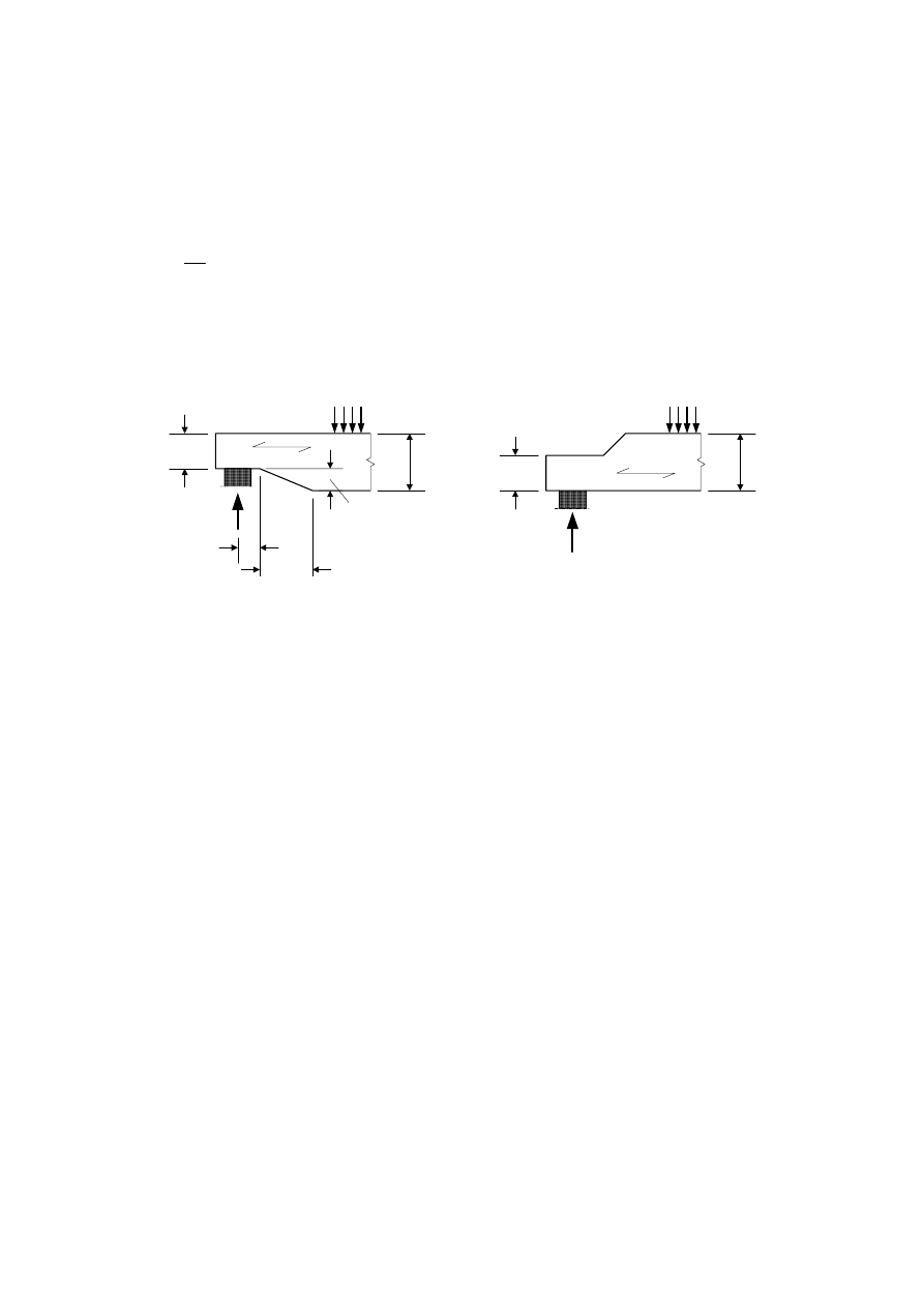
prEN 1995-1-1:2003 (E)
53
where:
i
is the notch inclination (see Figure 6.11a);
h
is the beam depth in mm;
x
is the distance from line of action of the support reaction to the corner of the notch;
ef
h
h
a =
n
k
ì
ï
= í
ï
î
4,5
for LVL
5
for
solid
timber
6,5
for glued laminated timber
(6.63)
(a)
(b)
i(h - h
ef
)
x
h
h -
h
ef
h
ef
h
ef
h
Figure 6.11 – End-notched beams
6.6 System
strength
(1) When several equally spaced similar members, components or assemblies are laterally
connected by a continuous load distribution system, the member strength properties may be
multiplied by a system strength factor
k
sys
.
(2) Provided the continuous load-distribution system is capable of transfering the loads from one
member to the neighbouring members, the factor
k
sys
should be 1,1.
(3) The strength verification of the load distribution system should be carried out assuming the
loads are of short-term duration.
NOTE: For roof trusses with a maximum centre to centre distance of 1,2 m it may be assumed that tiling
battens, purlins or panels can transfer the load to the neighbouring trusses provided that these load-
distribution members are continuous over at least two spans, and any joints are staggered.
(4) For laminated timber decks or floors the values of
k
sys
given in Figure 6.12 should be used.
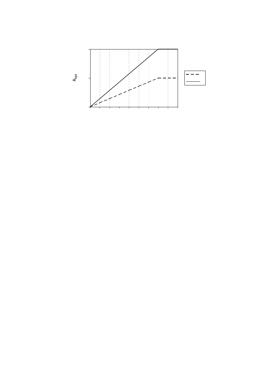
prEN 1995-1-1:2003 (E)
54
1
1,1
1,2
1
2
3
4
5
6
7
8
9
10
Number of loaded laminations
1
2
Key:
1 Nailed or screwed laminations
2 Laminations pre-stressed or glued together
Figure 6.12 – System strength factor k
sys
for laminated deck plates of solid timber or
glued laminated members
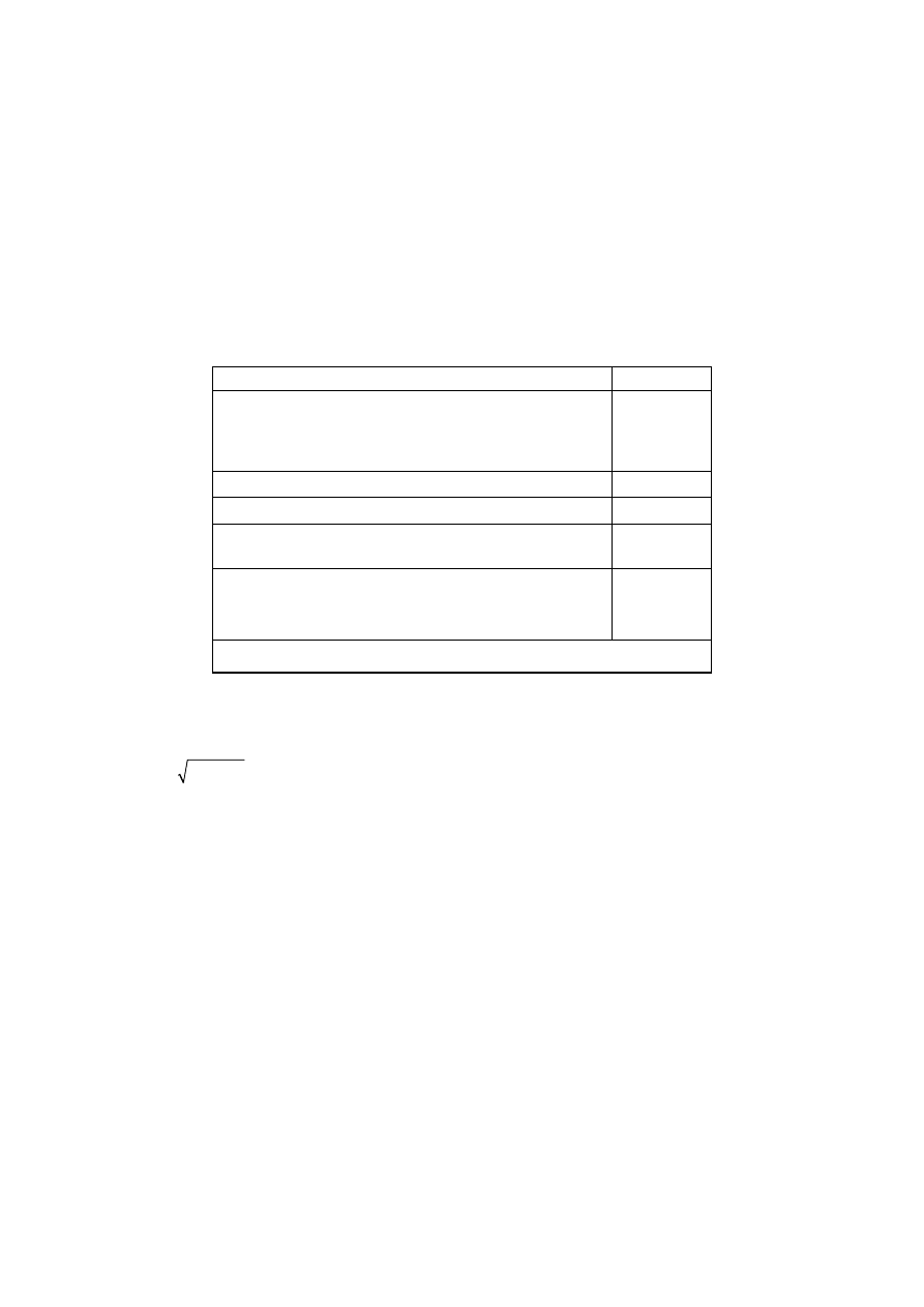
prEN 1995-1-1:2003 (E)
55
Section 7
Serviceability limit states
7.1 Joint
slip
(1) For joints made with dowel-type fasteners the slip modulus
K
ser
per shear plane per fastener
under service load should be taken from Table 7.1 with
r
m
in kg/m³ and
d
or
d
c
in mm. For the
definition of
d
c
, see EN 13271.
NOTE: In EN 26891 the symbol used is k
s
instead of K
ser
.
Table 7.1 – Values of K
ser
for fasteners and connectors in N/mm in timber-to-timber and
wood-based panel-to-timber connections
Fastener type
K
ser
Dowels
Bolts with or without clearance
a
Screws
Nails (with pre-drilling)
r
m
1,5
d
/23
Nails (without pre-drilling)
r
m
1,5
d
0,8
/30
Staples
r
m
1,5
d
0,8
/80
Split-ring connectors type A according to EN 912
Shear-plate connectors type B according to EN 912
r
m
d
c
/2
Toothed-plate connectors:
-
Connectors types C1 to C9 according to EN 912
1,5r
m
d
c
/4
-
Connectors type C10 and C11 according to EN 912
r
m
d
c
/2
a
The clearance should be added separately to the deformation.
(2) If the mean densities
r
m,1
and
r
m,2
of the two jointed wood-based members are different then
r
m
in the above expressions should be taken as
m
m,1 m,2
r
r r
=
(7.1)
(3) For steel-to-timber or concrete-to-timber connections, K
ser
should be based on
r
m
for the
timber member and may be multiplied by 2,0.
7.2
Limiting values for deflections of beams
(1) The components of deflection resulting from a combination of actions (see 2.2.3(5)) are
shown in Figure 7.1, where the symbols are defined as follows, see 2.2.3:
-
w
c
is the precamber (if applied);
-
w
inst
is the instantaneous deflection;
-
w
creep
is the creep deflection;
-
w
fin
is the final deflection;
-
w
net,fin
is the net final deflection.
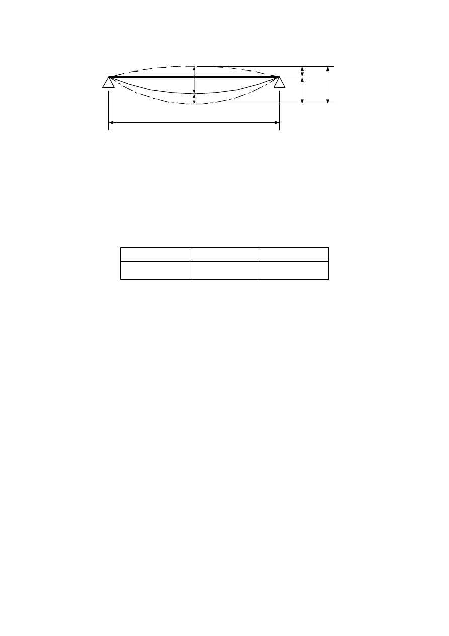
prEN 1995-1-1:2003 (E)
56
w
creep
w
inst
l
w
c
w
net,fin
w
fin
Figure 7.1 – Components of deflection
(2) The net deflection below a straight line between the supports, w
net,fin
, should be taken as:
net,fin
inst
creep
c
fin
c
w
w
w
w
w
w
=
+
-
=
-
(7.2)
NOTE: The recommended range of limiting values of deflections for beams with span
l is given in Table
7.2 depending upon the level of deformation deemed to be acceptable. Information on National choice
may be found in the National annex. For cantilevered beams, the values may be doubled.
Table 7.2 – Examples of limiting values for deflections of beams on two supports
w
inst
w
net,fin
w
fin
l/300 to l/500
l/250 to l/350
l/150 to l/300
7.3 Vibrations
7.3.1 General
(1)P It shall be ensured that the actions which can be reasonably anticipated on a member,
component or structure, do not cause vibrations that can impair the function of the structure or
cause unacceptable discomfort to the users.
(2) The vibration level should be estimated by measurements or by calculation taking into
account the expected stiffness of the member, component or structure and the modal damping
ratio.
(3) For floors, unless other values are proven to be more appropriate, a modal damping ratio of
z = 0,01 (i.e 1 %) should be assumed.
7.3.2
Vibrations from machinery
(1)P Vibrations caused by rotating machinery and other operational equipment shall be limited
for the unfavourable combinations of permanent load and variable loads that can be expected.
(2) For floors, acceptable levels for continuous vibration should be taken from figure 5a in
Appendix A of ISO 2631-2 with a multiplying factor of 1,0.
7.3.3 Residential
floors
(1) For residential floors with a fundamental frequency less than 8Hz (
f
1
£ 8Hz) a special
investigation should be made.
(2) For residential floors with a fundamental frequency greater than 8 Hz (
f
1
> 8 Hz) the
following requirements should be satisfied:
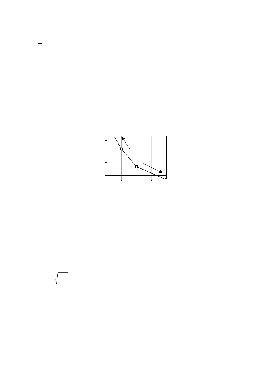
prEN 1995-1-1:2003 (E)
57
mm/kN
w
a
F
£
(7.3)
and
1
(
-1)
m/(Ns²)
f
v
b
z
£
(7.4)
where:
w is the maximum instantaneous vertical deflection caused by a vertical concentrated static
force F applied at any point on the floor, taking account of load distribution;
v
is the unit impulse velocity response, i.e. the maximum initial value of the vertical floor
vibration velocity (in m/s) caused by an ideal unit impulse (1 Ns) applied at the point of the
floor giving maximum response. Components above 40 Hz may be disregarded;
z is the modal damping ratio.
NOTE: The recommended range of limiting values of a and b and the recommended relationship between
a and b is given in Figure 7.2. Information on the National choice may be found in the National annex.
50
60
70
80
90
100
110
120
130
140
150
0
1
2
3
4
a [mm/kN]
b
1
2
Key:
1
Better
performance
2
Poorer
performance
Figure 7.2 — Recommended range of and relationship between a and b
(3) The calculations in 7.3.3(2) should be made under the assumption that the floor is unloaded,
i.e., only the mass corresponding to the self-weight of the floor and other permanent actions.
(4) For a rectangular floor with overall dimensions
l
´ b
,
simply supported along all four edges
and with timber beams having a span
l, the fundamental frequency f
1
may approximately be
calculated as
EI
f
m
p
=
l
l
1
2
(
)
2
(7.5)
where:
m
is the mass per unit area in kg/m²;
l
is the floor span, in m;
(
EI)
l
is the equivalent plate bending stiffness of the floor about an axis perpendicular to the
beam direction, in Nm²/m.

prEN 1995-1-1:2003 (E)
58
(5) For a rectangular floor with overall dimensions b×
l, simply supported along all four edges,
the value v may, as an approximation, be taken as:
n
v
mb
+
=
+
l
40
4(0,4
0,6
)
200
(7.6)
where:
v
is the unit impulse velocity response, in m/(Ns
2
);
n
40
is the number of first-order modes with natural frequencies up to 40 Hz;
b
is the floor width, in m;
m
is the mass, in kg/m
2
;
l is the floor span, in m.
The value of n
40
may be calculated from:
( )
( )
b
EI
b
n
EI
f
ì
ü
æ
ö
æ
ö
æ ö
ï
ï
ç
÷
=
ç
÷
í
ý
ç ÷
ç
÷
ç
÷ è ø
ï
ï
è
ø
è
ø
î
þ
l
l
0,25
2
4
40
1
40
-
1
(7.7)
where
(
EI
)
b
is the equivalent plate bending stiffness, in Nm
2
/m, of the floor about an axis parallel
to the beams, where
(
EI
)
b
<
(
EI
)
l
.

prEN 1995-1-1:2003 (E)
59
Section 8
Connections with metal fasteners
8.1 General
8.1.1 Fastener
requirements
(1)P Unless rules are given in this section, the characteristic load-carrying capacity, and the
stiffness of the connections shall be determined from tests according to EN 1075, EN 1380, EN
1381, EN 26891 and EN 28970. If the relevant standards describe tension and compression
tests, the tests for the determination of the characteristic load-carrying capacity shall be
performed in tension.
8.1.2 Multiple
fastener
connections
(1)P The arrangement and sizes of the fasteners in a connection, and the fastener spacings,
edge and end distances shall be chosen so that the expected strength and stiffness can be
obtained.
(2)P It shall be taken into account that the load-carrying capacity of a multiple fastener
connection, consisting of fasteners of the same type and dimension, is lower than the
summation of the individual load-carrying capacities for each fastener.
(3) When a connection comprises different types of fasteners, or when the stiffness of the
connections in respective shear planes of a multiple shear plane connection is different, their
compatibility should be verified.
(4) For one row of fasteners parallel to the grain direction, the effective characteristic load-
carrying capacity parallel to the row, F
v,ef,Rk
,
should be taken as:
v,ef,Rk
ef v,Rk
F
n F
=
(8.1)
where:
F
v,ef,Rk
is the effective characteristic load-carrying capacity of one row of fasteners parallel to
the grain;
n
ef
is the effective number of fasteners in line parallel to the grain;
F
v,Rk
is the characteristic load-carrying capacity of each fastener parallel to the grain.
NOTE: Values of n
ef
for rows parallel to grain are given in 8.3.1.1(8) and 8.5.1.1(5).
(5) For a force acting at an angle to the direction of the row, it should be verified that the force
component parallel to the row is less than or equal to the load-carrying capacity calculated
according to expression (8.1).
8.1.3
Multiple shear plane connections
(1) In multiple shear plane connections the resistance of each shear plane should be
determined by assuming that each shear plane is part of a series of three-member connections.
(2) To be able to combine the resistance from individual shear planes in a multiple shear plane
connection, the governing failure mode of the fasteners in the respective shear planes should
be compatible with each other and should not consist of a combination of failure modes (a), (b),
(g) and (h) from Figure 8.2 or modes (e), (f) and (j/l) from Figure 8.3 with the other failure
modes.
8.1.4
Connection forces at an angle to the grain
(1)P When a force in a connection acts at an angle to the grain, (see Figure 8.1), the possibility

prEN 1995-1-1:2003 (E)
60
of splitting caused by the tension force component, F
Ed
sin
a, perpendicular to the grain, shall be
taken into account.
(2)P To take account of the possibility of splitting caused by the tension force component,
F
Ed
sin
a, perpendicular to the grain, the following shall be satisfied:
v,Ed
90,Rd
F
F
£
(8.2)
with
v,Ed,1
v,Ed
v,Ed,2
max
=
F
F
F
ìï
í
ïî
(8.3)
where:
F
90,Rd
is the design splitting capacity, calculated from the characteristic splitting
capacity F
90,Rk
according to 2.4.3;
F
v,Ed,1
, F
v,Ed,2
are the design shear forces on either side of the connection. (see Figure 8.1).
(3) For softwoods, the characteristic splitting capacity for the arrangement shown in Figure 8.1
should be taken as:
e
90,Rk
e
h
F
b w
h
h
=
æ
ö
-
ç
÷
è
ø
14
1
(8.4)
where:
pl
w
w
ì
ìæ
ö
ï
ïç
÷
ï
íè
ø
= í
ï
ï
î
ï
î
0,35
max
for punchedmetalplate fasteners
100
1
1
for all other fasteners
(8.5)
and:
F
90,Rk
is the characteristic splitting capacity,
in N;
w
is a modification factor;
h
e
is the loaded edge distance to the centre of the most distant fastener or to the edge of
the punched metal plate fastener, in mm;
h
is the timber member height, in mm;
b
is the member thickness, in mm;
w
pl
is the width of the punched metal plate fastener parallel to the grain, in mm.
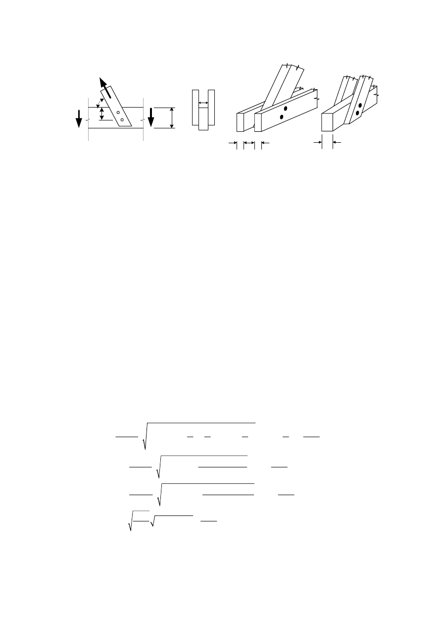
prEN 1995-1-1:2003 (E)
61
F
Ed
F
v,Ed,1
F
v,Ed,2
h
e
h
b
a
b
b/2
b/2
a)
b)
Figure 8.1 – Inclined force transmitted by a connection
8.1.5
Alternating connection forces
(1)P The characteristic load-carrying capacity of a connection shall be reduced if the connection
is subject to alternating internal forces due to long-term or medium-term actions.
(2)The effect on connection strength of long-term or medium-term actions alternating between a
tensile design force F
t,Ed
and a compressive design force F
c,Ed
should be taken into account by
designing the connection for (F
t,Ed
+ 0,5F
c,Ed
) and (F
c,Ed
+ 0,5F
t,Ed
).
8.2
Lateral load-carrying capacity of metal dowel-type fasteners
8.2.1 General
(1)P For the determination of the characteristic load-carrying capacity of connections with metal
dowel-type fasteners the contributions of the yield strength, the embedment strength, and the
withdrawal strength of the fastener shall be considered.
8.2.2
Timber-to-timber and panel-to-timber connections
(1) The characteristic load-carrying capacity for nails, staples, bolts, dowels and screws per
shear plane per fastener, should be taken as the minimum value found from the following
expressions:
- For fasteners in single shear
h,1,k
h,2,k
h,1,k
ax,Rk
y,Rk
h,1,k
ax,Rk
v,Rk
h,1,k
h,1
f
t d
f
t d
f
t d
F
t
t
t
t
t
t
t
t
M
f
t d
F
F
f
d t
f
b
b
b
b
b
b
b
b
b
b
b
é
ù
é
ù
æ ö
æ ö
æ
ö
ê
ú
ê
ú
+
+ +
+
-
+
+
ç ÷
ç ÷
ç
÷
ê
ú
+
ê
ú
è ø
è ø
è
ø
ë
û
ê
ú
ë
û
é
ù
+
=
ê
+
+
- ú +
+
ê
ú
ë
û
1
2
2
2
1
2
3
2
2
2
2
1
1
1
1
1
2
1
(a)
(b)
2
1
1
(c)
1
4
4 (2
)
min 1,05
2 (1
)
(d)
2
4
1,05
y,Rk
,k
ax,Rk
h,1,k
ax,Rk
y,Rk h,1,k
M
t d
F
f
d t
F
M
f
d
b
b
b
b
b
b
b
b
ì
ï
ï
ï
ï
ï
ï
ï
ïï
í
ï
ï
ï
é
ù
+
ï
ê
+
+
- ú +
+
ï
ê
ú
ë
û
ï
ï
+
ï
+
ïî
2
2
2
2
4 (1 2 )
2
(1
)
(e)
1 2
4
2
1,15
2
(f)
1
4
(8.6)
-
For fasteners in double shear:

prEN 1995-1-1:2003 (E)
62
h,1,k
h,2,k
y,Rk
h,1,k
ax,Rk
v,Rk
h,1,k
ax,Rk
y,Rk h,1,k
f
t d
f
t d
M
f
t d
F
F
f
d t
F
M
f
d
b
b
b
b
b
b
b
b
ì
ï
ï
ï
é
ù
+
ï
=
ê
+
+
- ú +
í
+
ê
ú
ï
ë
û
ï
ï
+
ï
+
î
1
2
1
2
1
(g)
0,5
(h)
4 (2
)
min 1,05
2 (1
)
(j)
2
4
2
1,15
2
(k)
1
4
(8.7)
with
h,2,k
h,1,k
f
f
b =
(8.8)
where:
F
v,Rk
is the characteristic load-carrying capacity per shear plane per fastener;
t
i
is the timber or board thickness or penetration depth, with i either 1 or 2, see also 8.3 to
8.7 ;
f
h,i,k
is the characteristic embedment strength in timber member i;
d
is the fastener diameter;
M
y,Rk
is the characteristic fastener yield moment;
b
is the ratio between the embedment strength of the members;
F
ax,Rk
is the characteristic axial withdrawal capacity of the fastener, see (2).
NOTE: Plasticity of joints can be assured when relatively slender fasteners are used. In that case, failure
modes (f) and (k) are governing.
(2) In the expressions (8.6) and (8.7), the first term on the right hand side is the load-carrying
capacity according to the Johansen yield theory, whilst the second term F
ax,Rk
/4 is the
contribution from the rope effect. The contribution to the load-carrying capacity due to the rope
effect should be limited to following percentages of the Johansen part:
-
Round nails
15 %
-
Square nails
25 %
-
Other nails
50 %
-
Screws
100%
-
Bolts
25
%
-
Dowels
0
%
If
F
ax,Rk
is not known then the contribution from the rope effect should be taken as zero.
For single shear fasteners the characteristic withdrawal capacity, F
ax,Rk
, is taken as the lower of
the capacities in the two members. The different modes of failure are illustrated in Figure 8.2. For
the withdrawal capacity, F
ax,Rk
, of bolts the resistance provided by the washers may be taken
into account, see 8.5.2(2).
(3) If no design rules are given below, the characteristic embedment strength f
h,k
should be
determined according to EN 383 and EN 14358.
(4) If no design rules are given below, the characteristic yield moment M
y,Rk
should be determined
according to EN 409 and EN 14358.
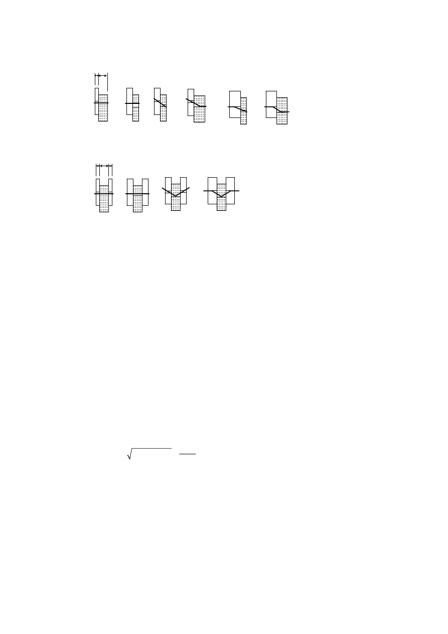
prEN 1995-1-1:2003 (E)
63
a
b
c
d
e
f
g
h
j
k
(1)
(2)
t
1
t
2
t
2
t
1
t
1
Key:
(1) Single shear
(2) Double shear
NOTE: The letters correspond to the references of the expressions (8.6) and (8.7)
Figure 8.2 – Failure modes for timber and panel connections.
8.2.3 Steel-to-timber
connections
(1) The characteristic load-carrying capacity of a steel-to-timber connection depends on the
thickness of the steel plates. Steel plates of thickness less than or equal to 0,5d are classified as
thin plates and steel plates of thickness greater than or equal to d
with the tolerance on hole
diameters being less than 0,1d are classified as thick plates. The characteristic load-carrying
capacity of connections with steel plate thickness between a thin and a thick plate should be
calculated by linear interpolation between the limiting thin and thick plate values.
(2)P The strength of the steel plate shall be checked.
(3) The characteristic load-carrying capacity for nails, bolts, dowels and screws per shear plane
per fastener should be taken as the minimum value found from the following expressions:
-
For a thin steel plate in single shear:
h,k
v,Rk
ax,Rk
y,Rk
h,k
f t d
F
F
M
f d
ì
ï
=
í
+
ïî
1
0,4
(a)
min
1,15 2
(b)
4
(8.9)
where:
F
v,Rk
is the characteristic load-carrying capacity per shear plane per fastener;
f
h,k
is the characteristic embedment strength in the timber member;
t
1
is the timber thickness or penetration depth;
d
is the fastener diameter;
M
y,Rk
is the characteristic fastener yield moment;
F
ax,Rk
is the characteristic withdrawal capacity of the fastener;
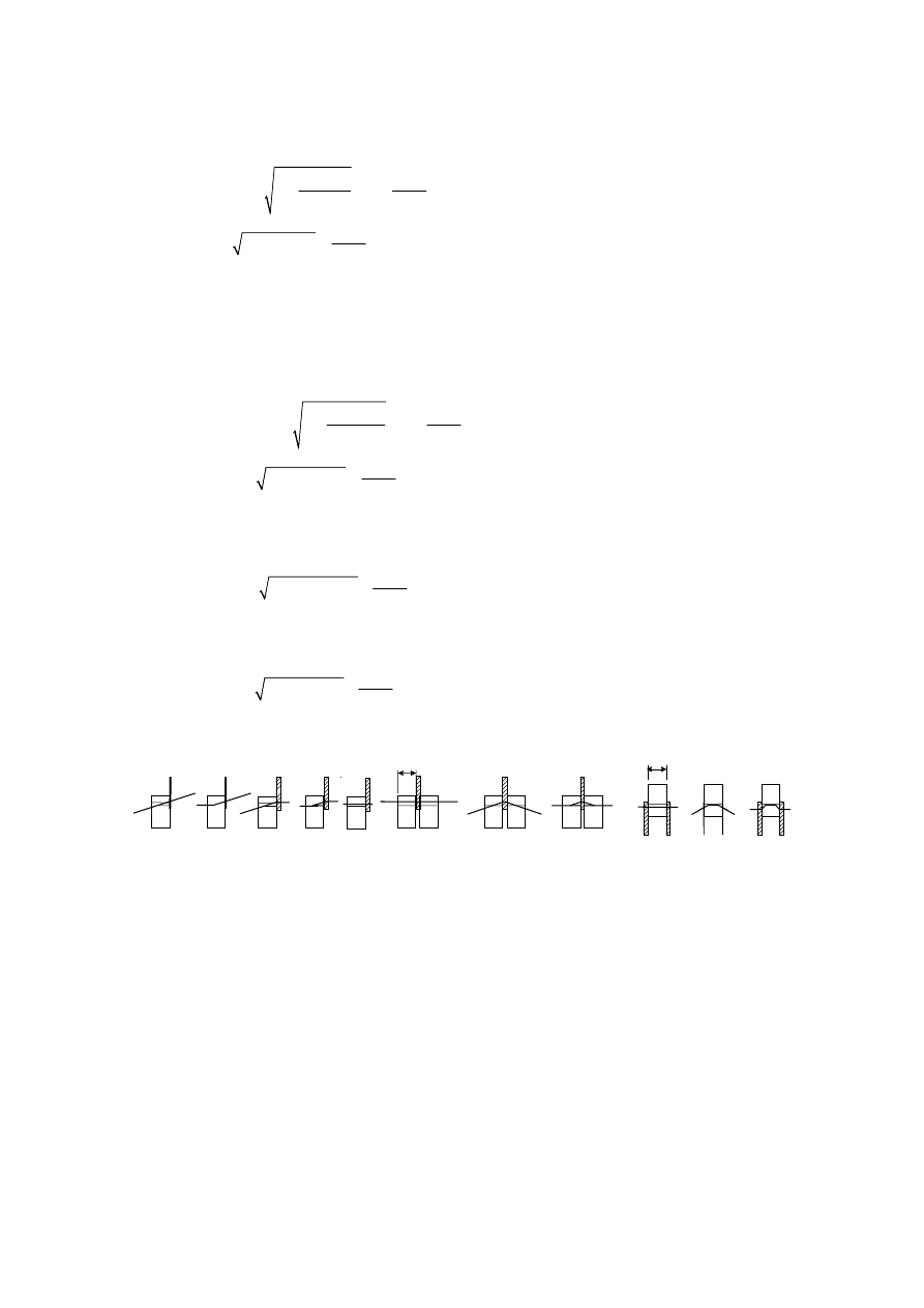
prEN 1995-1-1:2003 (E)
64
-
For a thick steel plate in single shear:
y,Rk
ax,Rk
h,k
h,k
ax,Rk
v,Rk
y,Rk
h,k
h,k
M
F
f t d
f d t
F
F
M
f d
f t d
ì
é
ù
ï
ê
+
- ú +
ï
ê
ú
ë
û
ïï
=
í
+
ï
ï
ï
ïî
1
2
1
1
4
2
1
(c)
4
min 2,3
(d)
4
(e)
(8.10)
-
For a steel plate of any thickness as the central member of a double shear connection:
h,1,k
y,Rk
ax,Rk
v,Rk
h,1,k
h,1,k
ax,Rk
y,Rk
h,1,k
f
t d
M
F
F
f
t d
f
d t
F
M
f
d
ì
ï
ï
ï
é
ù
ï
=
ê
+
- ú +
í
ê
ú
ï
ë
û
ï
ï
+
ïî
1
1
2
1
(f)
4
min
2
1
(g)
4
2,3
(h)
4
(8.11)
-
For thin steel plates as the outer members of a double shear connection:
h,2,k
v,Rk
ax,Rk
y,Rk
h,2,k
f
t d
F
F
M
f
d
ì
ï
=
í
+
ïî
2
0,5
(j)
min
1,15 2
(k)
4
(8.12)
-
For thick steel plates as the outer members of a double shear connection:
h,2,k 2
v,Rk
ax,Rk
y,Rk
h,2,k
0 5
(l)
2 3
(m)
4
f
t d
F
F
M
f
d
ì
ï
=
í
+
ïî
,
min
,
(8.13)
NOTE 1: The different failure modes are illustrated in Figure 8.3
a
b
c
d
e
f
g
h
j/l
k
t
1
t
2
m
Figure 8.3 – Failure modes for steel-to-timber connections
(4) For the limitation of the rope effect F
ax,Rk
8.2.2(2) applies.
(5)P It shall be taken into account that the load-carrying capacity of steel-to-timber connections
with a loaded end may be reduced by failure along the perimeter of the fastener group.
NOTE: A method of determining the strength of the fastener group is given in Annex A (informative).

prEN 1995-1-1:2003 (E)
65
8.3 Nailed
connections
8.3.1
Laterally loaded nails
8.3.1.1 General
(1) The symbols for the thicknesses in single and double shear connections (see Figure 8.4) are
defined as follows:
t
1
is:
the headside thickness in a single shear connection;
the minimum of the head side timber thickness and the pointside penetration in a double shear
connection;
t
2
is:
the pointside penetration in a single shear connection;
the central member thickness in a double shear connection.
(2) Timber should be pre-drilled when:
-
the characteristic density of the timber is greater than 500 kg/m³;
-
the
diameter
d
of the nail exceeds 8 mm.
(3) For square and grooved nails, the nail diameter
d
should be taken as the side dimension.
(4) For smooth nails produced from wire with a minimum tensile strength of 600 N/mm², the
following characteristic values for yield moment should be used:
u
y,Rk
u
f
d
M
f
d
ì
ïï
= í
ï
ïî
2,6
2,6
180
for round nails
600
270
for square nails
600
(8.14)
where:
M
y,Rk
is the characteristic value for the yield moment, in Nmm;
d
is the nail diameter as defined in EN 14592, in mm;
f
u
is the tensile strength of the wire, in N/mm².
(5) For nails with diameters up to 8 mm, the following characteristic embedment strengths in
timber and LVL apply:
-
without
predrilled
holes
h,k
k
f
d
r
=
2
-0,3
0,082
N/mm (8.15)
- with predrilled holes
h,k
k
d
f
r
=
2
0,082 (1- 0,01 )
N/mm (8.16)
where:
r
k
is the characteristic timber density, in kg/m³;
d is the nail diameter, in mm.
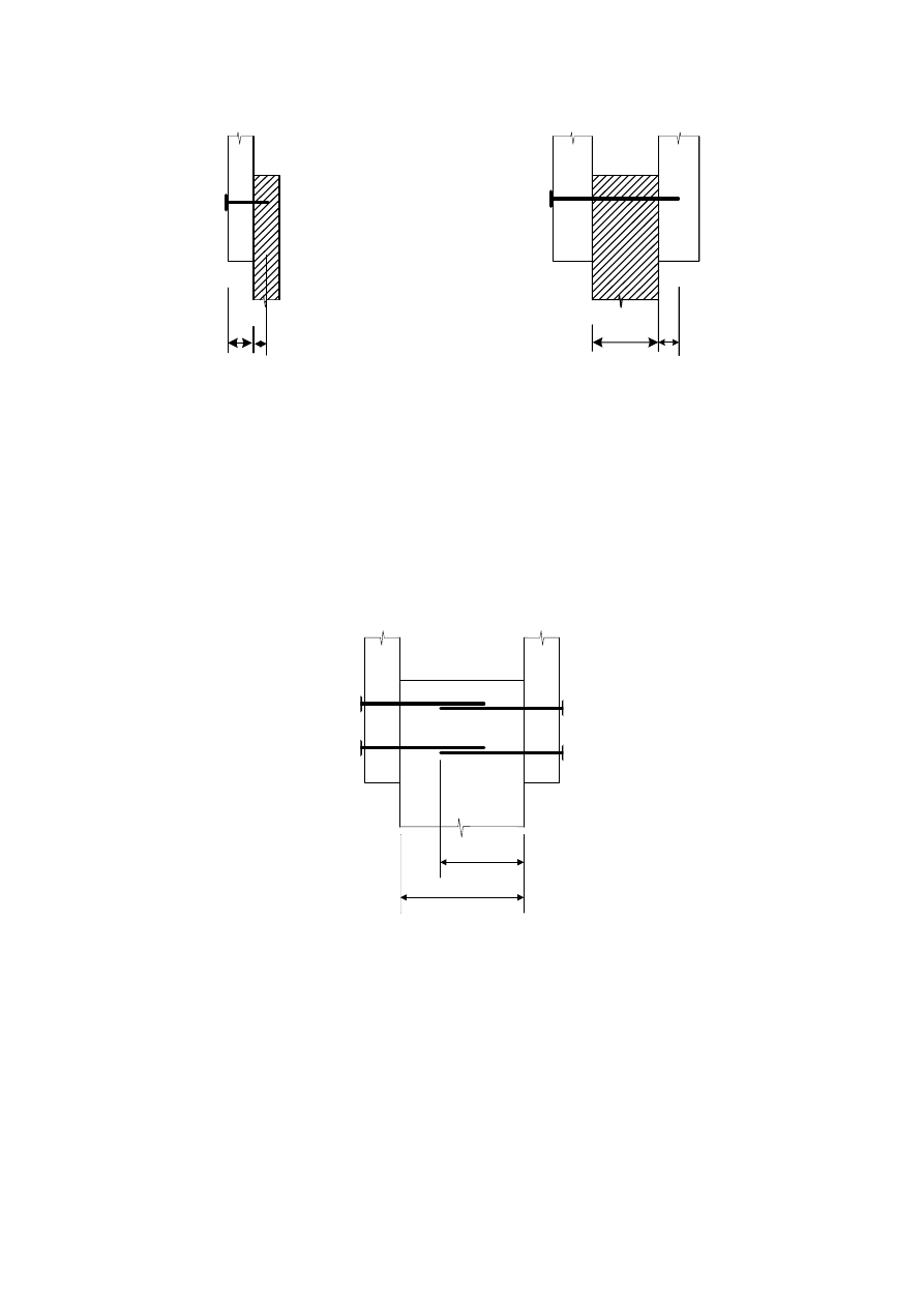
prEN 1995-1-1:2003 (E)
66
(a)
(b)
t
1
t
2
t
1
t
2
Figure 8.4 – Definitions of t
1
and t
2
(a) single shear connection, (b) double shear
connection
(6) For nails with diameters greater than 8 mm the characteristic embedment strength values for
bolts according to 8.5.1 apply.
(7) In a three-member connection, nails may overlap in the central member provided (t - t
2
) is
greater than 4d
(see Figure 8.5).
t
t
2
Figure 8.5 – Overlapping nails
(8) For one row of n nails parallel to the grain, unless the nails of that row are staggered
perpendicular to grain by at least 1d (see figure 8.6), the load-carrying capacity parallel to the
grain (see 8.1.2(4)) should be calculated using the effective number of fasteners n
ef
, where:
ef
ef
k
n
n
=
(8.17)
where:
n
ef
is the effective number of nails in the row;
n
is the number of nails in a row;
k
ef
is given in Table 8.1.
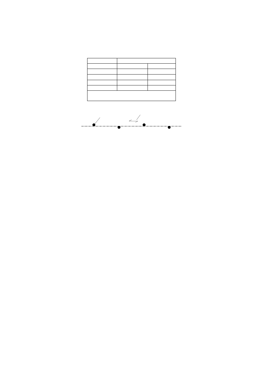
prEN 1995-1-1:2003 (E)
67
Table 8.1 – Values of k
ef
Spacing
a
k
ef
Not
predrilled
Predrilled
a
1
³ 14d
1,0 1,0
a
1
= 10d
0,85 0,85
a
1
= 7d
0,7 0,7
a
1
= 4d
- 0,5
a
For intermediate spacings, linear
interpolation of k
ef
is permitted
2
1
Key:
1 Nail
2 Grain direction
Figure 8.6
– Nails in a row parallel to grain staggered perpendicular to grain
by d
(9) For a force acting at an angle to the direction of the grain, it should be verified, that the force
component parallel to the grain is less or equal to the load-carrying capacity calculated according
to (8).
(10) There should be at least two nails in a connection.
(11) Requirements for structural detailing and control of nailed connections are given in 10.4.2.
8.3.1.2
Nailed timber-to-timber connections
(1) For smooth nails the pointside penetration length should be at least 8d.
(2) For nails other than smooth nails, as defined in EN 14592, the pointside penetration length
should be at least 6d.
(3) Smooth nails in end grain should not be considered capable of transmitting lateral forces.
(4) As an alternative to 8.3.1.2(3), for nails in end grain the following rules apply:
- In secondary structures smooth nails may be used. The design values of the load-carrying
capacity should be taken as 1/3 of the values for nails installed at right angles to the grain;
- Nails other than smooth nails, as defined in EN 14592, may be used in structures other than
secondary structures. The design values of the load-carrying capacity should be taken as 1/3
of the values for smooth nails of equivalent diameter installed at right angles to the grain,
provided that:
- the nails are only laterally loaded;
- there are at least three nails per connection;
- the pointside penetration is at least 10d;
- the connection is not exposed to service class 3 conditions;
- the prescribed spacings and edge distances given in Table 8.2 are satisfied.

prEN 1995-1-1:2003 (E)
68
Note 1: An example of a secondary structure is a fascia board nailed to rafters.
Note 2: The recommended application rule is given in 8.3.1.2(3). The National choice may be specified in
the National annex.
(5) Minimum spacings and edge and end distances are given in Table 8.2,
where (see Figure 8.7):
a
1
is the spacing of nails within one row parallel to grain;
a
2
is the spacing of rows of nails perpendicular to grain;
a
3,c
is the distance between nail and unloaded end;
a
3,t
is the distance between nail and loaded end;
a
4,c
is the distance between nail and unloaded edge;
a
4,t
is the distance between nail and loaded edge;
a is the angle between the force and the grain direction.
Table 8.2 – Minimum spacings and edge and end distances for nails
Spacing or
distance
(see Figure
8.7)
Angle
a
Minimum spacing or end/edge distance
without predrilled holes
with predrilled
holes
ρ
k
≤ 420 kg/m
3
420
kg/m
3
< ρ
k
≤ 500 kg/m
3
Spacing a
1
(parallel to
grain)
0
°
≤ α ≤ 360
°
d < 5 mm:
(5+5│cos α│) d
d ≥ 5 mm:
(5+7│cos α│) d
(7+8│cos α│) d (4+│cos α│) d
Spacing a
2
(perpendicular
to grain)
0
°
≤ α ≤ 360
°
5d
7d (3+│sin α│) d
Distance a
3,t
(loaded end)
-90
°
≤ α ≤ 90
°
(10+5cos
α
) d (15+5cos
α
) d (7+5cos
α
) d
Distance a
3,c
(unloaded
end)
90
°
≤ α ≤ 270
°
10d 15d
7d
Distance a
4,t
(loaded edge)
0
°
≤ α ≤ 180
°
d < 5 mm:
(5+2 sin α) d
d
³ 5 mm:
(5 + 5 sin
a) d
d < 5 mm:
(7+2 sin α) d
d
³ 5 mm:
(7 + 5 sin
a) d
d < 5 mm:
(3 +2 sin α) d
d
³ 5 mm:
(3 + 4 sin
a) d
Distance a
4,c
(unloaded
edge)
180
°
≤ α ≤ 360
°
5d
7d
3d
(6) Timber should be pre-drilled when the thickness of the timber members is smaller than
(
)
k
d
t
d
r
ì
ï
=
í
-
ïî
7
max
13
30
400
(8.18)
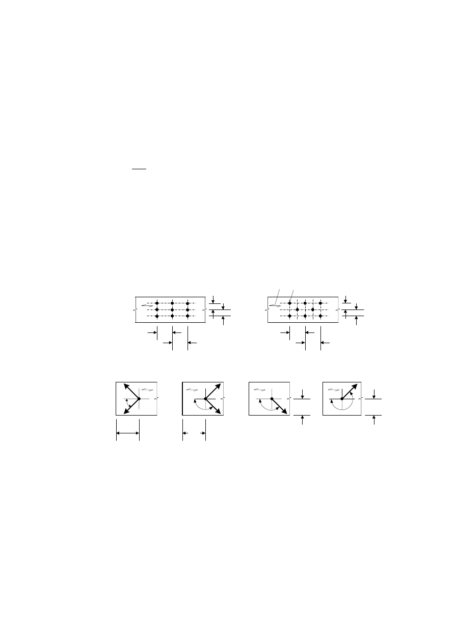
prEN 1995-1-1:2003 (E)
69
where:
t
is the minimum thickness of timber member to avoid pre-drilling, in mm;
r
k
is the characteristic timber density in kg/m³;
d
is the nail diameter, in mm.
(7) Timber of species especially sensitive to splitting should be pre-drilled when the thickness of
the timber members is smaller than
(
)
k
d
t
d
r
ì
ï
=
í
-
ïî
14
max
13
30
200
(8.19)
Expression (8.19) may be replaced by expression (8.18) for edge distances given by:
a
4
≥
10 d
for ρ
k
≤
420 kg/m
3
a
4
≥
14 d
for 420 kg/m
3
≤
ρ
k
≤
500 kg/
3
.
Note: Examples of species sensitive to splitting are fir (abies alba), Douglas fir (pseudotsuga menziesii)
and spruce (picea abies). It is recommended to apply 8.3.1.2(7) for species fir (abies alba) and Douglas fir
(pseudotsuga menziesii). The National choice may be specified in the National annex.
a
a
a
a
a
3,t
a
3,c
a
4,
t
a
4,
c
-90°
£ a £ 90°
90°
£ a £ 270°
0°
£ a £ 180°
180°
£ a £ 360°
(1)
(2)
(3)
(4)
a
2
a
2
a
1
a
1
a
1
a
1
a
2
a
2
a)
b)
1
2
Key:
(1) Loaded end
(2) Unloaded end
(3) Loaded edge
(4) Unloaded
edge
1 Fastener
2 Grain direction
Figure 8.7 – Spacings and end and edge distances
(a) Spacing parallel to grain in a row and perpendicular to grain between rows, (b) Edge

prEN 1995-1-1:2003 (E)
70
and end distances
8.3.1.3
Nailed panel-to-timber connections
(1) Minimum nail spacings for all nailed panel-to-timber connections are those given in Table
8.2, multiplied by a factor of 0,85. The end/edge distances for nails remain unchanged unless
otherwise stated below.
(2) Minimum edge and end distances in plywood members should be taken as 3d
for an
unloaded edge (or end) and (3 + 4 sin α) d for a loaded edge (or end).
(3) For nails with a head diameter of at least 2d, the characteristic embedment strengths are as
follows:
- for plywood:
h,k
k
f
d
r
-
=
0,3
0,11
(8.20)
where:
f
h,k
is the
characteristic embedment strength, in N/mm
2
;
r
k
is the characteristic plywood density in kg/m³;
d
is the nail diameter, in mm;
-
for hardboard in accordance with EN 622-2:
0,3 0,6
h,k
30
f
d
t
-
=
(8.21)
where:
f
h,k
is the
characteristic embedment strength, in N/mm
2
;
d
is the nail diameter, in mm;
t
is the panel thickness, in mm.
-
for particleboard and OSB:
h,k
f
d
t
-
=
0,7 0,1
65
(8.22)
where:
f
h,k
is the
characteristic embedment strength, in N/mm
2
;
d
is the nail diameter, in mm;
t
is the panel thickness, in mm.
8.3.1.4 Nailed steel-to-timber connections
(1) The minimum edge and end distances for nails given in Table 8.2 apply. Minimum nail
spacings are those given in Table 8.2, multiplied by a factor of 0,7.
8.3.2
Axially loaded nails
(1)P Smooth nails shall not be used to resist permanent or long-term axial loading.
(2) For threaded nails, only the threaded part should be considered capable of transmitting axial
load.
(3) Nails in end grain should be considered incapable of transmitting axial load.

prEN 1995-1-1:2003 (E)
71
(4) The characteristic withdrawal capacity of nails,
F
ax,Rk
, for nailing perpendicular to the grain
(Figure 8.8 (a) and for slant nailing (Figure 8.8 (b)), should be taken as the smaller of the values
found from the following expressions:
-
For nails other than smooth nails, as defined in EN 14592:
ax,k
pen
ax,Rk
head,k
h
f
d t
F
f
d
ìï
= í
ïî
2
(a)
(b)
(8.23)
-
For smooth nails:
ax,k
pen
ax,Rk
ax,k
head,k
h
f
d t
F
f
d t
f
d
ìï
= í
+
ïî
2
(a)
(b)
(8.24)
where:
f
ax,k
is the characteristic pointside withdrawal strength;
f
head,k
is the characteristic headside pull-through strength;
d
is the nail diameter according to 8.3.1.1;
t
pen
is the pointside penetration length or the length of the threaded part in the pointside
member;
t
is the thickness of the headside member;
d
h
is the nail head diameter.
(5) The characteristic strengths f
ax,k
and
f
head,k
should be determined by tests in accordance with
EN1382, EN1383 and EN 14358 unless specified in the following.
(6) For smooth nails with a pointside penetration of at least 12d, the characteristic values of the
withdrawal and pull-through strengths should be found from the following expressions:
ax,k
k
f
r
-
=
´
6
2
20 10
(8.25)
head,k
k
f
r
-
=
´
6
2
70 10
(8.26)
where:
r
k
is the characteristic timber density in kg/m³;
(7) For smooth nails, the pointside penetration t
pen
should be at least 8d. For nails with a pointside
penetration smaller than 12d the withdrawal capacity should be multiplied by (
t
pen
/4d – 2). For
threaded nails, the pointside penetration should be at least 6d. For nails with a pointside
penetration smaller than 8d the withdrawal capacity should be multiplied by (t
pen
/2d – 3).
(8) For structural timber which is installed at or near fibre saturation point, and which is likely to
dry out under load, the values of f
ax,k
and f
head,k
should be multiplied by 2/3.
(9) The spacings, end and edge distances for laterally loaded nails apply to axially loaded nails.
(10) For slant nailing the distance to the loaded edge should be at least 10d (see Figure 8.8(b)).
There should be at least two slant nails in a connection.
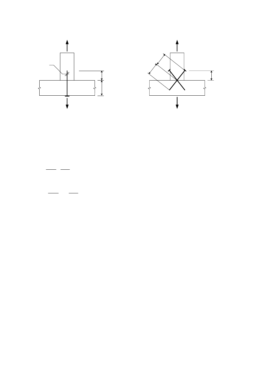
prEN 1995-1-1:2003 (E)
72
d
(a)
(b)
t
pen
t
pen
t
t
³ 10d
Figure 8.8 – (a) Nailing perpendicular to grain and (b) slant nailing
8.3.3 Combined
laterally
and axially loaded nails
(1) For connections subjected to a combination of axial load (F
ax,Ed
) and lateral load (F
v,Ed
) the
following expressions should be satisfied:
-
for smooth nails:
ax,Ed
v,Ed
ax,Rd
v,Rd
F
F
+
F
F
£1 (8.27)
- for nails other than smooth nails, as defined in EN 14592:
ax,Ed
v,Ed
ax,Rd
v,Rd
2
2
F
F
+
F
F
æ
ö æ
ö
£
ç
÷ ç
÷
è
ø è
ø
1 (8.28)
where:
F
ax,Rd
and F
v,Rd
are the design load-carrying capacities of the connection loaded with axial load or
lateral load respectively.
8.4 Stapled
connections
(1) The rules given in 8.3, except for 8.3.1.1(5) and (6) and 8.3.1.2(7), apply for round or nearly
round or rectangular staples with bevelled or symmetrical pointed legs.
(2) For staples with rectangular cross-sections the diameter d should be taken as the square root
of the product of both dimensions.
(3) The width b of the staple crown should be at least 6d, and the pointside penetration length t
2
should be at least 14d, see Figure 8.9.
(4) There should be at least two staples in a connection.
(5) The lateral design load-carrying capacity per staple per shear plane should be considered as
equivalent to that of two nails with the staple diameter, provided that the angle between the
crown and the direction of the grain of the timber under the crown is greater than 30°, see
Figure 8.10. If the angle between the crown and the direction of the grain under the crown is
equal to or less than 30°, then the lateral design load-carrying capacity should be multiplied by a
factor of 0,7.
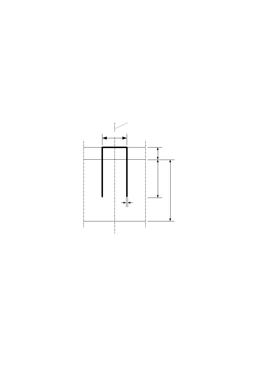
prEN 1995-1-1:2003 (E)
73
(6) For staples produced from wire with a minimum tensile strength of 800 N/mm², the following
characteristic yield moment per leg should be used:
y,Rk
M
d
=
2,6
240
(8.29)
where:
M
y,Rk
is the characteristic yield moment, in Nmm;
d
is the staple leg diameter, in mm.
(7) For a row of n staples parallel to the grain, the load-carrying capacity in that direction should be
calculated using the effective number of fasteners n
ef
according to 8.3.1.1(8)
(8) Minimum staple spacings, edge and end distances are given in Table 8.3, and illustrated in
Figure 8.10 where Θ is the angle between the staple crown and the grain direction.
b
d
(1)
t
1
t
2
t
Key:
(1) staple centre
Figure 8.9 – Staple dimensions
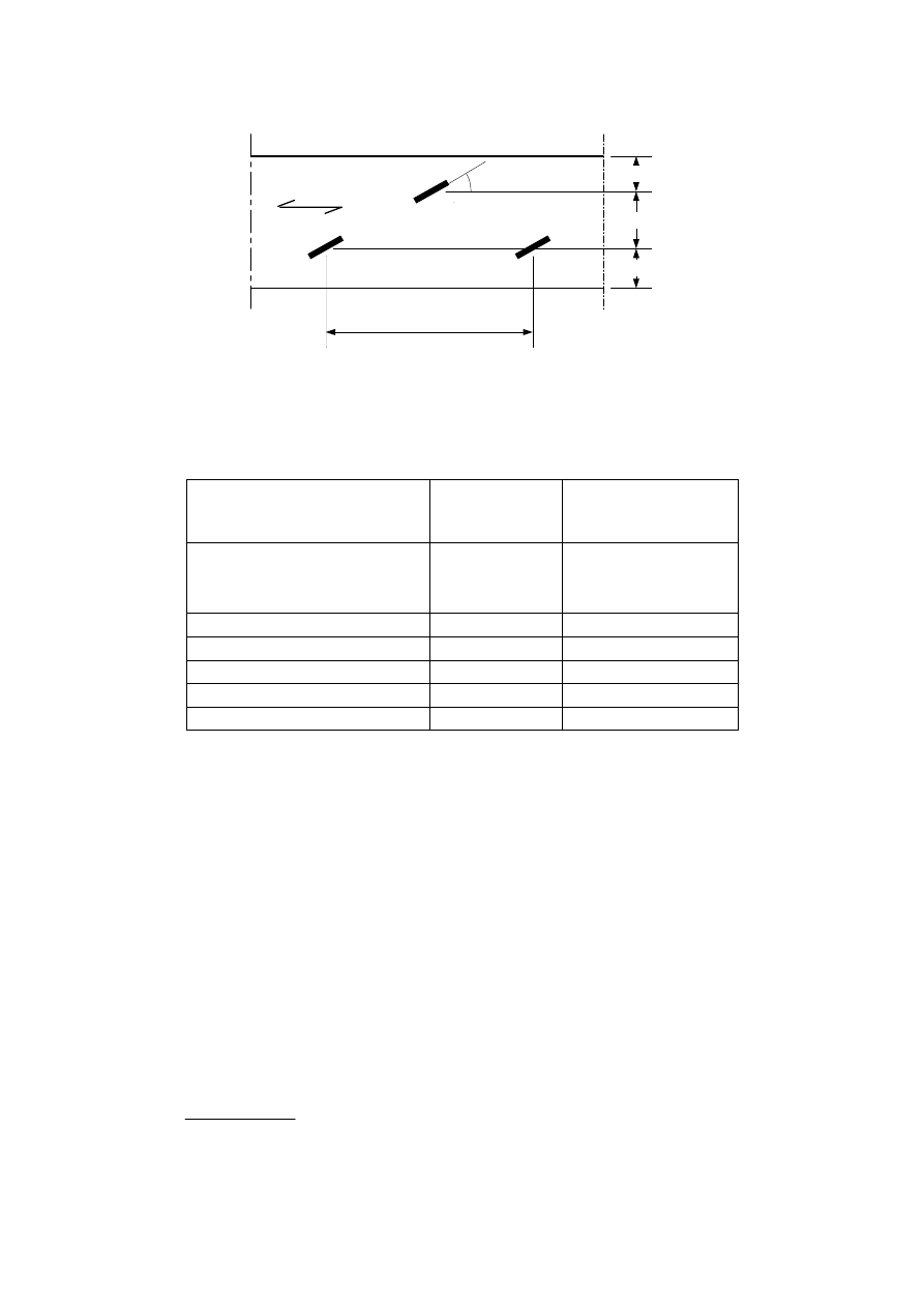
prEN 1995-1-1:2003 (E)
74
Q
a
1
a
4
a
2
a
4
Figure 8.10 – Definition of spacing for staples
Table 8.3 – Minimum spacings and edge and end distances for staples
Spacing and edge/end
distances
(see Figure 8.7)
Angle
Minimum spacing or
edge/end distance
a
1
(parallel to grain)
for
q ³ 30°
for
q < 30°
0
°
≤ α ≤ 360
°
(10 + 5│cos α│) d
(15 + 5│cos α│) d
a
2
(perpendicular to grain)
0
°
≤ α ≤ 360
0°
15
d
a
3,t
(loaded end)
-90
°
≤ α ≤ 90
°
(15 + 5│cos α│) d
a
3,c
(unloaded end)
90
°
≤ α ≤ 270
°
15
d
a
4,t
(loaded edge)
0
°
≤ α ≤ 180
°
(15 + 5│sin α│) d
a
4,c
(unloaded edge)
180
°
≤ α ≤ 360
°
10
d
8.5 Bolted
connections
8.5.1
Laterally loaded bolts
8.5.1.1
General and bolted timber-to-timber connections
(1) For bolts the following characteristic value for the yield moment should be used:
y,Rk
u,k
=
f
d
M
2,6
0,3
(8.30)
where:
M
y,Rk
is the characteristic value for the yield moment, in Nmm;
f
u,k
is the characteristic tensile strength, in N/mm²;
d
is the bolt diameter, in mm.
(2) For bolts up to 30 mm diameter, the following characteristic embedment strength values in
timber and LVL should be used, at an angle
a to the grain:
h,0,k
h,α,k
90
sin
cos
2
2
f
=
f
+
k
a
a
(8.31)
prEN 1995-1-1:2003 (E)
75
h,0,k
k
=
d
f
r
0,082 (1- 0,01 )
(8.32)
where:
90
d
d
k
d
+
ì
ï
=
+
í
ï
+
î
1,35 0,015
for softwoods
1,30 0,015
for LVL
0,90 0,015
for hardwoods
(8.33)
and:
f
h,0,k
is the characteristc embedment strength parallel to grain, in N/mm
2
;
r
k
is the characteristic timber density, in kg/m³;
α
is the angle of the load to the grain;
d
is the bolt diameter, in mm.
(3) Minimum spacings and edge and end distances should be taken from Table 8.4, with symbols
illustrated in Figure 8.7.
Table 8.4 – Minimum values of spacing and edge and end distances for bolts
Spacing and end/edge
distances
(see Figure 8.7)
Angle
Minimum spacing or
distance
a
1
(parallel to grain)
0
°
≤ α ≤ 360
°
(4
+
│cos α│) d
a
2
(perpendicular to
grain)
0
°
≤ α ≤ 360
°
4
d
a
3,t
(loaded end)
-90
°
≤ α ≤ 90
°
max
(7
d; 80 mm)
a
3,c
(unloaded end)
90
°
≤ α < 150
°
150
°
≤ α < 210
°
210
°
≤ α ≤ 270
°
max([1 + 6 sin α) d; 4d)
4 d
max([1 + 6 sin α) d; 4d)
a
4,t
(loaded edge)
0
°
≤ α ≤ 180
°
max([2 + 2 sin α) d; 3d)
a
4,c
(unloaded edge)
180
°
≤ α ≤ 360
°
3
d
(4) For one row of n bolts parallel to the grain direction, the load-carrying capacity parallel to grain,
see 8.1.2(4), should be calculated using the effective number of bolts n
ef
where:
n
n =
a
n
d
ì
ï
í
ï
î
ef
0,9
1
4
min
13
(8.34)
where:
a
1
is the spacing between bolts in the grain direction;
d is the bolt diameter
n is the number of bolts in the row.
For loads perpendicular to grain, the effective number of fasteners should be taken as
ef
n
n
=
(8.35)
For angles 0° < α < 90° between load and grain direction, n
ef
may be determined by linear
interpolation between expressions (8.34) and (8.35).
(5) Requirements for minimum washer dimensions and thickness in relation to bolt diameter are

prEN 1995-1-1:2003 (E)
76
given in 10.4.3
8.5.1.2
Bolted panel-to-timber connections
(1) For plywood the following embedment strength, in N/mm
2
, should be used at all angles to
the face grain:
h,0,k
k
=
d
f
r
0,11 (1- 0,01 )
(8.36)
where:
r
k
is the characteristic plywood density, in kg/m³;
d is the bolt diameter, in mm.
(2) For particleboard and OSB the following embedment strength value, in N/mm
2
, should be
used at all angles to the face grain:
h,0,k
=
d
t
f
-0,6 0,2
50
(8.37)
where:
d is the bolt diameter, in mm;
t is the panel thickness, in mm.
8.5.1.3 Bolted
steel-to-timber
connections
(1) The rules given in 8.2.3 apply.
8.5.2
Axially loaded bolts
(1) The axial load-bearing capacity and withdrawal capacity of a bolt should be taken as the
lower value of:
- the bolt tensile capacity;
- the load-bearing capacity of either the washer or (for steel-to-timber connections) the steel
plate.
(2) The bearing capacity of a washer should be calculated assuming a characteristic
compressive strength on the contact area of 3,0f
c,90,k
.
(3) The bearing capacity per bolt of a steel plate should not exceed that of a circular washer with
a diameter which is the minimum of:
- 12t, where t is the plate thickness;
- 4d, where d is the bolt diameter.
8.6 Dowelled
connections
(1) The rules given in 8.5.1 except 8.5.1.1(3) apply.
(2) The dowel diameter should be greater than 6 mm and less than 30 mm.
(3) Minimum spacing and edge and end distances are given in Table 8.5, with symbols
illustrated in Figure 8.7.
prEN 1995-1-1:2003 (E)
77
Table 8.5 – Minimum spacings and edge and end distances for dowels
Spacing and edge/end
distances
(see Figure 8.7)
Angle
Minimum spacing or
edge/end distance
a
1
(parallel to grain)
0
°
≤ α ≤ 360
°
(3 + 2│cos α│) d
a
2
(perpendicular to
grain)
0
°
≤ α ≤ 360
°
3
d
a
3,t
(loaded end)
-90
°
≤ α ≤ 90
0°
max
(7
d; 80 mm)
a
3,c
(unloaded end)
90
0°
≤ α < 150
°
150
°
≤ α < 210
°
210
°
≤ α ≤ 270
°
max(a
3,t
│sin α│) d; 3d)
3 d
max(a
3,t
│sin α│) d; 3d)
a
4,t
(loaded edge)
0
°
≤ α ≤ 180
°
max([2 + 2 sin α) d; 3d)
a
4,c
(unloaded edge)
180
°
≤ α ≤ 360
°
3
d
(4) Requirements for dowel hole tolerances are given in 10.4.4.
8.7 Screwed
connections
8.7.1
Laterally loaded screws
(1)P The effect of the threaded part of the screw shall be taken into account in determining the
load-carrying capacity, by using an effective diameter d
ef
.
(2) For smooth shank screws, where the outer thread diameter is equal to the shank diameter,
the rules given in 8.2 apply, provided that:
- The effective diameter d
ef
is taken as the smooth shank diameter;
- The smooth shank penetrates into the member containing the point of the screw by not less
than 4d.
(3) Where the conditions in (2) are not satisfied, the screw load-carrying capacity should be
calculated using an effective diameter d
ef
taken as 1,1 times the thread root diameter.
(4) For smooth shank screws with a diameter d > 6 mm, the rules in 8.5.1 apply.
(5) For smooth shank screws with a diameter of 6 mm or less, the rules of 8.3.1 apply.
(6) Requirements for structural detailing and control of screwed joints are given in 10.4.5.
8.7.2
Axially loaded screws
(1) The following failure modes should be verified when assessing the load-carrying capacity of
connections with axially loaded screws:
- the withdrawal capacity of the threaded part of the screw;
- for screws used in combination with steel plates, the tear-off capacity of the screw head should
be greater than the tensile strength of the screw;
- the pull-through strength of the screw head;
- the tension strength of the screw;
- for screws used in conjunction with steel plates, failure along the circumference of a group of
screws (block shear or plug shear);
(2) Minimum spacing and edge distances for axially loaded screws should be taken from Table
prEN 1995-1-1:2003 (E)
78
8.6.
Table 8.6 – Minimum spacings and edge distances for axially loaded screws
Screws driven
Minimum
spacing
Minimum edge
distance
At right angle to the
grain
4d
4d
In end grain
4d 2,5d
(3) The minimum pointside penetration length of the threaded part should be 6d.
(4) The characteristic withdrawal capacity of connections with axially loaded screws should be
taken as:
ax,α,Rk
ef
ef
ax,α,k
F
n
d l
f
=
p
0,8
(
)
(8.38)
where:
F
ax,
a,Rk
is the characteristic withdrawal capacity of the connection at an angle α to the grain;
n
ef
is the effective number of screws;
d
is the outer diameter measured on the threaded part;
l
ef
is the pointside penetration length of the threaded part minus one screw diameter;
f
ax,
a,k
is the characteristic withdrawal strength at an angle
a to the grain.
(5) The characteristic withdrawal strength at an angle
a to the grain should be taken as:
ax,k
ax,α,k
f
f
a
a
=
+
2
2
sin
1,5cos
(8.39)
with:
ax,k
k
f
r
-
=
´
3
1,5
3,6 10
(8.40)
where:
f
ax,α,k
is the characteristic withdrawal strength at an angle
a to the grain;
f
ax,k
is the characteristic withdrawal strength perpendicular to the grain;
r
k
is the characteristic density, in kg/m
3
.
NOTE: Failure modes in the steel or in the timber around the screw are brittle, i.e. with small
ultimate deformation and therefore have a limited possibility for stress redistribution.
(6)P The pull-through capacity of the head shall be determined by tests, in accordance with
EN1383.
(7) For a connection with a group of screws loaded by a force component parallel to the shank,
the effective number of screws is given by:
ef
n
n
=
0,9
(8.41)
where:
n
ef
is the effective number of screws;
n is the number of screws acting together in a connection.

prEN 1995-1-1:2003 (E)
79
8.7.3
Combined laterally and axially loaded screws
(1) For screwed connections subjected to a combination of axial load and lateral load, expression
(8.28) should be satisfied.
8.8
Connections made with punched metal plate fasteners
8.8.1 General
(1)P Connections made with punched metal plate fasteners shall comprise punched metal plate
fasteners of the same type, size and orientation, placed on each side of the timber members.
(2) The following rules apply only to punched metal plate fasteners with two orthogonal
directions.
8.8.2 Plate
geometry
(1) The symbols used to define the geometry of a punched metal plate fastener joint are given
in Figure 8.11 and defined as follows:
x-direction main direction of plate;
y-direction perpendicular to the main plate direction;
a
angle between the x-direction and the force (tension: 0° ≤ γ < 90°, compression:
90° ≤ γ < 180°);
b
angle between the grain-direction and the force;
g
angle between the x-direction and the connection line;
A
ef
area of the total contact surface between the plate and the timber, reduced by 5
mm from the edges of the timber and by a distance in the grain direction from the
end of timber equal to 6 times the fastener’s nominal thickness;
l
dimension of the plate measured along the connection line.
8.8.3 Plate
strength
properties
(1)P The plate shall have characteristic values for the following properties, determined in
accordance with EN 14545 from tests carried out in accordance with EN 1075:
f
a,0,0
the anchorage capacity per unit area for
a = 0° and b = 0°;
f
a,90,90
the anchorage capacity per unit area for
a = 90° and b = 90°;
f
t,0
the tension capacity per unit width of plate for
a = 0°;
f
c,0
the compression capacity per unit width of plate for
a = 0°;
f
v,0
the shear capacity per unit width of plate in the x-direction;
f
t,90
the tension capacity per unit width of plate for
a = 90°;
f
c,90
the compression capacity per unit width of plate for
a = 90°;
f
v,90
the shear capacity per unit width of plate in the y-direction;
k
1
,k
2
,
a
o
constants.
(2)P In order to calculate the design tension, compression and shear capacities of the plate the
value of k
mod
shall be taken as 1,0.
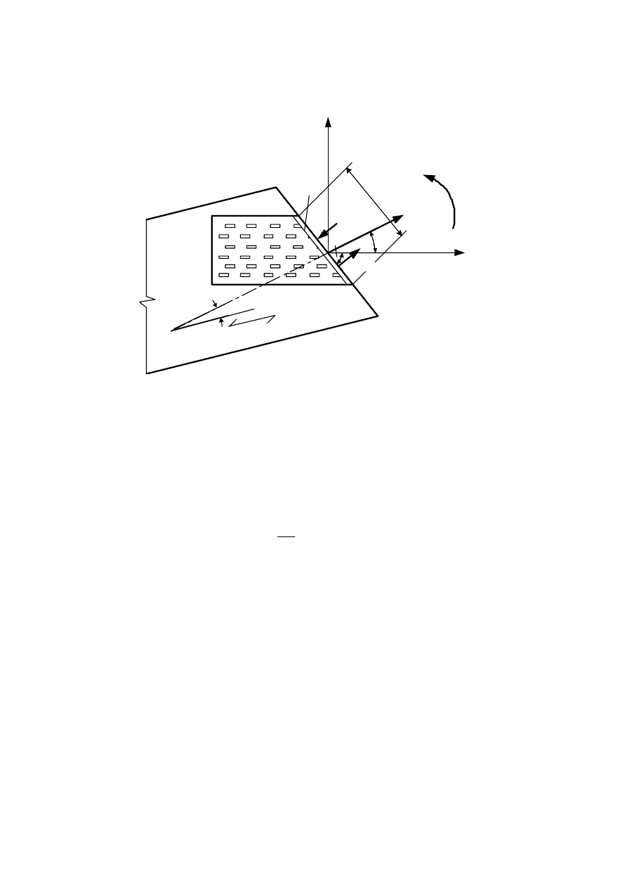
prEN 1995-1-1:2003 (E)
80
b
l
a
F
Ed
F
M,Ed
F
M,Ed
M
Ed
g
x
y
1
2
Key:
1 Border of effective area
2 Grain direction
Figure 8.11 – Geometry of punched metal plate connection loaded by a force F
Ed
and
moment M
Ed
8.8.4 Plate
anchorage
strengths
(1) The characteristic anchorage strength per plate f
a,
a,b,k
should either be derived from tests or
calculated from:
(
)
(
)
(
)
(
)
a,α,0,k
a,α,0,k
a,90,90,k
a,α,β,k
a,0,0,k
a,0,0,k
a,90,90,k
f
f
f
f
f
f
f
b
a b
ì
-
-
ï
°
=
í
ï
-
-
î
45
max
sin max
,
for
b £ 45°, or
(8.42)
(
)
(
)
(
)
a,α,β,k
a,0,0,k
a,0,0,k
a,90,90,k
f
f
f
f
a b
=
-
-
sin max
,
for 45° <
b
£
90°
(8.43)
(2) The characteristic anchorage strength per plate parallel to grain should be taken as:
(
)
a,0,0,k
a,α,0,k
a,0,0,k
f
k
f
f
k
k
a
a a
a
a a
a
a
+
£
ìï
= í
+
+
-
< £
°
ïî
1
0
1 0
2
0
0
when
when
90
(8.44)
The constants k
1
, k
2
and
a
0
should be determined from anchorage tests in accordance with
EN 1075 and derived in accordance with the procedure given in EN 14545 for the actual plate
type.
prEN 1995-1-1:2003 (E)
81
8.8.5
Connection strength verification
8.8.5.1 Plate
anchorage
capacity
(1) The design anchorage stress
t
F,d
on a single punched metal plate fastener imposed by a
force
F
Ed
and the design anchorage stress
t
M,d
imposed from a moment M
Ed
, should be taken
as:
A,Ed
F,d
ef
F
A
t
=
(8.45)
A,Ed
M,d
p
M
W
t
=
(8.46)
with:
ef
p
A
W
r dA
=
ò
(8.47)
where:
F
A,Ed
is the design force acting on a single plate at the centroid of the effective area (i.e. half
of the total force in the timber member);
M
A,Ed
is the design moment acting on a single plate on the centroid of the effective area;
dA
is the segmental area of the punched metal plate fastener;
r
is the distance from the centre of gravity of the plate to the segmental plate area
d
A;
A
ef
is the effective plate area.
(2) As an alternative to expression (8.47), W
p
may be conservatively approximated from:
ef
p
A d
W
=
4
(8.48)
with:
ef
ef
ef
A
d
h
h
æ
ö
=
+
ç
÷
è
ø
2
2
(8.49)
where:
h
ef
is the maximum height of the effective anchorage area perpendicular to the longest side.
(3) Contact pressure between timber members may be taken into account to reduce the value
of F
Ed
in compression provided that the gap between the members has an average value, which
is not greater than 1,5 mm, and a maximum value of 3 mm. In such cases the connection
should be designed for a minimum compressive design force of F
A,Ed
/2.
(4) Contact pressure between the timber members in chord splices in compression may be
taken into account by designing the single plate for a design force, F
A,Ed
, and a design moment
M
A,Ed
, according to the following expressions:
(
)
Ed
Ed
A,Ed
Ed
M
F
F
F
h
b
b
æ
ö
=
-
+
ç
÷
ç
÷
è
ø
2
2
3
cos
sin
2
2
(8.50)
Ed
A,Ed
M
M
=
2
(8.51)

prEN 1995-1-1:2003 (E)
82
where:
F
Ed
is the design axial force of the chord acting on a single plate (compression or zero);
M
Ed
is the design moment of the chord acting on a single plate;
h
is the height of the chord.
(5) The following expression should be satisfied:
F,d
M,d
a,α,β,d
a,0,0,d
f
f
t
t
æ
ö
æ
ö
+
£
ç
÷
ç
÷
ç
÷
ç
÷
è
ø
è
ø
2
2
1 (8.52)
8.8.5.2 Plate
capacity
(1) For each joint interface, the forces in the two main directions should be taken as:
x,Ed
Ed
M,Ed
F
F
F
a
g
=
±
cos
2
sin (8.53)
y,Ed
Ed
M,Ed
F
F
F
a
g
=
±
sin
2
cos (8.54)
where:
F
Ed
is the design force in a single plate (i.e. half of the total force in the timber member)
F
M,Ed
is the design force from the moment on a single plate (F
M,Ed
=2
M
Ed
/
l
)
(2) The following expression should be satisfied:
y,Ed
x,Ed
x,Rd
y,Rd
F
F
F
F
æ
ö
æ
ö
+
£
ç
÷
ç
÷
ç
÷
ç
÷
è
ø
è
ø
2
2
1
(8.55)
where:
F
x,Ed
and F
y,Ed
are the design forces acting in the
x
and
y
direction,
F
x,Rd
and F
y,Rd
are the corresponding design values of the plate capacity. They are
determined from the maximum of the characteristic capacities at sections
parallel or perpendicular to the main axes, based upon the following
expressions for the characteristic plate capacities in these directions
n,0,k
x,Rk
v,0,k
f
F
f
g g
g
g
ì
-
ï
=
í
ïî
l
l
0
sin(
sin(2 ))
max
cos
(8.56)
n,90,k
y,Rk
v,90,k
f
F
k f
g
g
ìï
=
í
ïî
l
l
cos
max
sin
(8.57)
with
t,0,k
x,Ed
N,0,k
c,0,k
x,Ed
f
F
f
f
F
ìï
= í
£
ïî
for
>0
for
0
(8.58)
t,90,k
y,Ed
n,90,k
c,90,k
y,Ed
f
F
f
f
F
ìï
= í
£
ïî
for
>0
for
0
(8.59)
v
x,Ed
x,Ed
k
F
k
F
g
+
ìï
= í
£
ïî
1
sin(2 )
for
>0
1
for
0
(8.60)
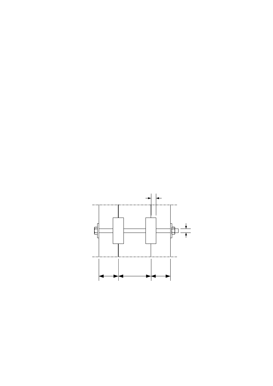
prEN 1995-1-1:2003 (E)
83
where
g
0
and k
v
are constants determined from shear tests in accordance with EN 1075 and
derived in accordance with the procedure given in EN 14545 for the actual plate type.
(3) If the plate covers more than two connection lines on the member then the forces in each
straight part of the connection line should be determined such that equilibrium is fulfilled and
that expression (8.55) is satisfied in each straight part of the connection line. All critical sections
should be taken into account.
8.9
Split ring and shear plate connectors
(1) For connections made with ring connectors of type A or shear plate connectors of type B
according to EN 912 and EN 14545, and with a diameter not bigger than 200 mm, the
characteristic load-carrying capacity parallel to grain,
F
v,0,Rk
per connector and per shear plane
should be taken as:
c
v,0,Rk
e
c
k k k k
d
F
k k h
d
ìï
=
í
ïî
1,5
1
2
3
4
1
3
(35
)
(a)
min
(31,5
)
(b)
(8.61)
where:
F
v,0,Rk
is the characteristic load-carrying capacity parallel to the grain, in N;
d
c
is the connector diameter, in mm;
h
e
is the embedment depth, in mm;
k
i
are modification factors, with i = 1 to 4, defined below.
(2) The minimum thickness of the outer timber members should be 2,25h
e
, and of the inner timber
member should be 3,75h
e
, where h
e
is the embedment depth, see Figure 8.12.
t
2
h
e
t
1
t
1
d
Figure 8.12 – Dimensions for connections with split ring and shear plate connectors
(3) The factor k
1
should be taken as:

prEN 1995-1-1:2003 (E)
84
e
e
t
h
t
h
k
ì
ï
ï
ïï
=
í
ï
ï
ï
ïî
1
2
1
1
3
5
min
(8.62)
(4) The factor k
2
applies to a loaded end (-30
°
£
a
£
30
°
) and should be taken as:
a
3,t
c
k
k
a
d
ì
ï
=
í
ï
î
2
min
2
(8.63)
where:
a
k
ì
= í
î
1,25 for connections with one connector per shear plane
1,0
for connections with more than one connector per shear plane
(8.64)
a
3,t
is given in Table 8.7.
For other values of
a
, k
2
= 1,0.
(5) The factor
k
3
should be taken as:
r
ì
ï
=
í
ïî
3
k
1,75
min
350
k
(8.65)
where
r
k
is the characteristic density of the timber, in kg/m
3
.
(6) The factor k
4
, which depends on the materials connected, should be taken as:
k
ì
= í
î
4
1,0 for timber-to-timber connections
1,1 for
steel-to-timber
connections
(8.66)
(7) For connections with one connector per shear plane loaded in an unloaded end situation
(150°
£
a
£
210°), the condition (a) in expression (8.61) should be disregarded.
(8) For a force at an angle
a
to the grain, the characteristic load-carrying capacity,
F
a,Rk
per
connector per shear plane should be calculated using the following expression:
v,0,Rk
v,α,Rk
2
2
90
F
F
k
a
a
=
+
sin
cos
(8.67)
with:
90
c
d
k
=
+
1,3 0,001
(8.68)
where:
F
v,0,Rk
is the characteristic load-carrying capacity of the connector for a force parallel to grain
according to expression (8.61);
d
c
is the connector diameter, in mm.
(9) Minimum spacing and edge and end distances are given in Table 8.7, with the symbols
illustrated in Figure 8.7.
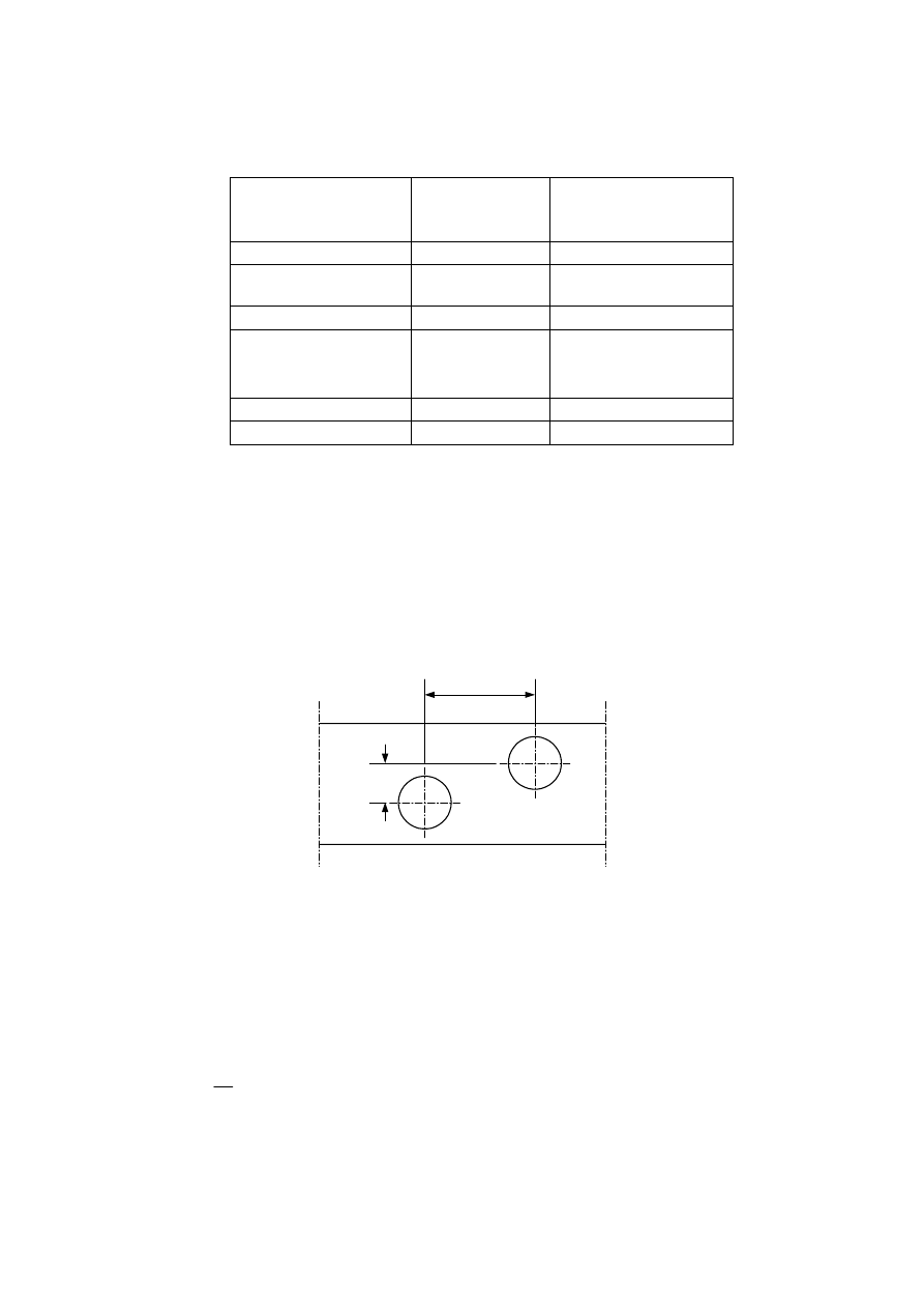
prEN 1995-1-1:2003 (E)
85
Table 8.7 – Minimum spacings and edge and end distances for ring and shear plate
connectors.
Spacing and edge/end
distances
(see Figure 8.7)
Angle to grain
Minimum spacings
and edge/end
distances
a
1
(parallel to grain)
0
°
≤
α
≤ 360
°
(1,2 + 0,8│cos
α
│)
d
c
a
2
(perpendicular to
grain)
0
°
≤
α
≤ 360
°
1,2
d
c
a
3,t
(loaded end)
-90
°
≤
α
≤ 90
°
1,5
d
c
a
3,c
(unloaded end)
90
°
≤
α
< 150
°
150
°
≤
α
< 210
°
210
°
≤
α
≤ 270
°
(0,4 + 1,6│sin
α
│)
d
c
1,2 d
c
(0,4 + 1,6│sin
α
│)
d
c
a
4,t
(loaded edge)
0
°
≤
α
≤ 180
0°
(0,6 + 0,2│sin
α
│)
d
c
a
4,c
(unloaded edge)
180
°
≤
α
≤ 360
0°
0,6
d
c
(10) When the connectors are staggered (see Figure 8.13), the minimum spacings parallel and
perpendicular to the grain should comply with the following expression:
a1
a1
a2
a2
k
k
k
k
£
£
ìï
+
³
í £ £
ïî
2
2
0
1
(
)
(
)
1
with
0
1
(8.69)
where:
k
a1
is a reduction factor for the minimum distance a
1
parallel to the grain;
k
a2
is a reduction factor for the minimum distance a
2
perpendicular to the grain.
k
a1
a
1
k
a2
a
2
Figure 8.13 – Reduced distances for connectors
(11) The spacing parallel to grain, k
a1
a
1
may further be reduced by multiplication by a factor k
s
,
red
,
with 0,5 ≤ k
s,red
≤ 1,0, provided that the load-carrying capacity is multiplied by a factor
R,red
s,red
k
k
=
+
0,2 0,8
(8.70)
(12) For a row of connectors parallel to the grain , the load-carrying capacity in that direction
should be calculated using the effective number of connectors n
ef
where:
ef
n
= n
n
+
2 ( 1-
)( - 2)
20
(8.71)
where:
n
ef
is the effective number of connectors;

prEN 1995-1-1:2003 (E)
86
n
is the number of connectors in a line parallel to grain.
(13) Connectors should be considered as positioned parallel to the grain where k
a2
a
2
< 0,5
k
a1
a
1
.
8.10 Toothed-plate
connectors
(1) The characteristic load-carrying capacity of connections made using toothed-plate
connectors should be taken as the summation of the characteristic load-carrying capacity of the
connectors themselves and the connecting bolts according to 8.5.
(2) The characteristic load-carrying capacity F
v,Rk
per toothed-plate connector for connectors of
type C according to EN 912 (single-sided: type C2, C4, C7, C9, C11; double sided: type C1, C3,
C5, C6, C8, C10) and EN 14545 should be taken as:
c
v,Rk
c
k k k d
F
k k k d
ìï
= í
ïî
1,5
1 2 3
1,5
1 2 3
18
for single-sided types
25
for double-sided types
(8.72)
where:
F
v,Rk
is the characteristic load-carrying capacity per toothed-plate connector, in N.
k
i
are modification factors, with i = 1 to 3, defined below.
d
c
is:
- the toothed-plate connector diameter for types C1, C2, C6, C7, C10 and C11, in mm;
- the toothed-plate connector side length for types C5, C8 and C9, in mm;
- the square root of the product of both side lengths for types C3 and C4, in mm.
(3) Clause 8.9(2) applies.
(4) The factor
k
1
should be taken as:
e
e
t
k
h
t
h
ì
ï
ï
ïï
=
í
ï
ï
ï
ïî
1
1
2
1
min
3
5
(8.73)
where:
t
1
is the side member thickness;
t
2
is the middle member thickness;
h
e
is the tooth penetration depth, in mm.
(5) The factor k
2
should be taken as:
- For types C1 to C9:
3,t
a
k
d
ì
ï
=
í
ï
î
2
c
1
min
1,5
(8.74)
with

prEN 1995-1-1:2003 (E)
87
c
d
a
d
ì
ï
=
í
ï
î
3,t
1,1
max 7
80 mm
(8.75)
where:
d is the bolt diameter, in mm;
d
c
is explained in (2) above.
- For types C10 and C11:
a
k
d
ì
ï
=
í
ï
î
3,t
2
c
1
min
2,0
(8.76)
with
c
d
a
d
ì
ï
=
í
ï
î
3,t
1,5
max 7
80 mm
(8.77)
where:
d
is the bolt diameter in mm;
d
c
is explained in (2) above.
(6) The factor k
3
should be taken as:
k
r
ì
ï
=
í
ïî
3
k
min
1,5
350
(8.78)
where
r
k
is the characteristic density of the timber, in kg/m
3
.
(7) For toothed-plate connector types C1 to C9, minimum spacings and edge and end distances
should be taken from Table 8.8, with the symbols illustrated in Figure 8.7.
(8) For toothed-plate connector types C10 and C11, minimum spacing and edge and end
distances should be taken from Table 8.9, with the symbols illustrated in Figure 8.7.
(9) Where connectors of types C1, C2, C6 and C7 with circular shape are staggered, 8.9(10)
applies.
(10) For bolts used with toothed-plate connectors, 10.4.3 applies.

prEN 1995-1-1:2003 (E)
88
Table 8.8 – Minimum spacings and edge and end distances for toothed-plate connector
types C1 to C9.
Spacings and
edge/end distances
(see Figure 8.7)
Angle to grain
Minimum spacings
and edge/end
distances
a
1
(parallel to grain)
0
°
≤
α ≤ 360
°
(1,2 + 0,3│cos
α│) d
c
a
2
(perpendicular to
grain)
0
°
≤
α ≤ 360
°
1,2
d
c
a
3,t
(loaded end)
-90
°
≤
α ≤ 90
°
2,0
d
c
a
3,c
(unloaded end)
90
°
≤
α < 150
°
150
0
≤
α < 210
°
210
°
≤
α ≤ 270
°
(0,9 + 0,6│sin
α│) d
c
1,2 d
c
(0,9 + 0,6│sin
α│) d
c
a
4,t
(loaded edge)
0
°
≤
α ≤ 180
°
(0,6 + 0,2│sin
α│) d
c
a
4,c
(unloaded edge)
180
°
≤
α ≤ 360
°
0,6
d
c
Table 8.9 – Minimum spacings and edge and end distances for toothed-plate connector
types C10 and C11.
Spacings and
edge/end distances
(see Figure 8.7)
Angle to grain
Minimum spacings
and edge/end
distances
a
1
(parallel to grain)
0
°
≤
α ≤ 360
°
(1,2 + 0,8│cos
α│) d
c
a
2
(perpendicular to
grain)
0
°
≤
α ≤ 360
°
1,2
d
c
a
3,t
(loaded end)
-90
°
≤
α ≤ 90
°
2,0
d
c
a
3,c
(unloaded end)
90
°
≤
α < 150
°
150
°
≤
α < 210
°
210
°
≤
α ≤ 270
°
(0,4 + 1,6│sin
α│) d
c
1,2 d
c
(0,4 + 1,6│sin
α│) d
c
a
4,t
(loaded edge)
0
°
≤
α ≤ 180
°
(0,6 + 0,2│sin
α│) d
c
a
4,c
(unloaded edge)
180
°
≤
α ≤ 360
°
0,6
d
c
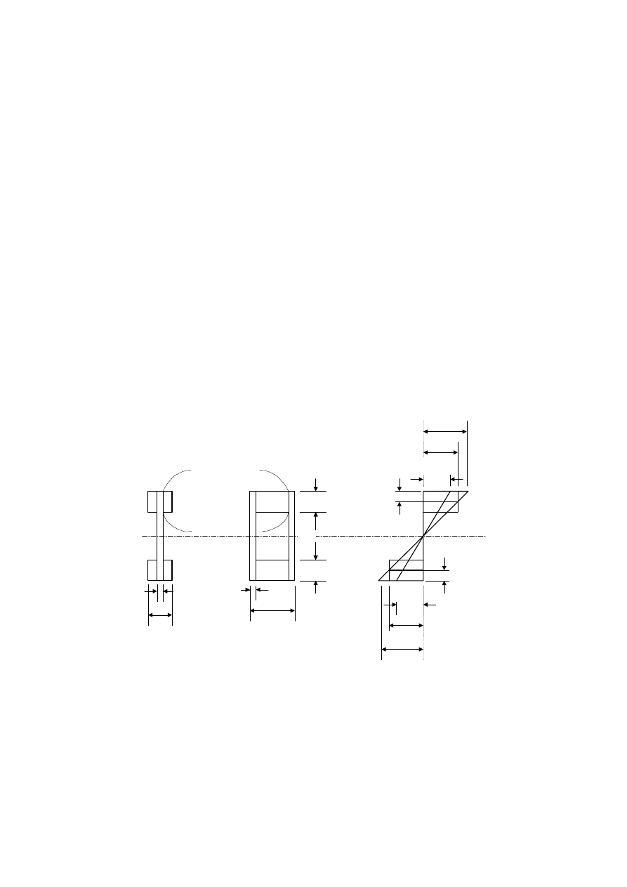
prEN 1995-1-1:2003 (E)
89
Section 9 Components and assemblies
9.1 Components
9.1.1
Glued thin-webbed beams
(1) If a linear variation of strain over the depth of the beam is assumed, the axial stresses in the
wood-based flanges should satisfy the following expressions:
f,c,max,d
m,d
f
s
£
(9.1)
f,t,max,d
m,d
f
s
£
(9.2)
f,c,d
c c,0,d
k f
s
£
(9.3)
f,t,d
t,0,d
f
s
£
(9.4)
where:
s
f,c,max,d
is the extreme fibre flange design compressive stress;
s
f,t,max,d
is the extreme fibre flange design tensile stress;
s
f,c,d
is the mean flange design compressive stress;
s
f,t,d
is the mean flange design tensile stress;
k
c
is a factor which takes into account lateral instability.
b
h
f,c
h
w
h
f,t
h
f,c
/2
h
f,t
/2
s
f,c
s
f,c,max
s
w,c,max
(1)
(2)
1
1
1
1
b
w
b
b
w
s
w,t,max
s
f,t
s
f,t,max
Key:
(1) compression
(2) tension
Figure 9.1 – Thin-webbed beams

prEN 1995-1-1:2003 (E)
90
(3) The factor k
c
may be determined (conservatively, especially for box beams) according to
6.3.2 with
c
z
b
l
æ
ö
=
ç
÷
è
ø
l
12
(9.5)
where:
l
c
is the distance between the sections where lateral deflection of the compressive flange is
prevented;
b is given in Figure 9.1.
If a special investigation is made with respect to the lateral instability of the beam as a whole, it
may be assumed that
k
c
= 1,0.
(4) The axial stresses in the webs should satisfy the following expressions:
w,c,d
c,w,d
f
s
£
(9.6)
w,t,d
t,w,d
f
s
£
(9.7)
where:
s
w,c,d
and
s
w,t,d
are the design compressive and tensile stresses in the webs;
f
c,w,d
and
f
t,w,d
are the design compressive and tensile bending strengths of the webs.
(5) Unless other values are given, the design in-plane bending strength of the webs should be
taken as the design tensile or compressive strength.
(6)P It shall be verified that any glued splices have sufficient strength.
(7) Unless a detailed buckling analysis is made it should be verified that:
w
w
h
b
£
70
(9.8)
and
f,t
f,c
w w
v,0,d w
w
w
v,w,Ed
f,t
f,c
w
v,0,d
w
w
w
w
h
h
b h
f
h
b
h
F
h
h
b
f
b
h
b
h
ì
+
æ
ö
+
£
ï
ç
÷
ï
è
ø
£ í
+
æ
ö
ï
+
£
£
ç
÷
ï
è
ø
î
2
0,5(
)
1
for
35
0,5(
)
35 1
for
35
70
(9.9)
where:
F
v,w,Ed
is the design shear force acting on each web;
h
w
is the clear distance between flanges;
h
f,c
is the compressive flange depth;
h
f,t
is the tensile flange depth;
b
w
is the width of each web;
f
v,0,d
is the design panel shear strength.
(8) For webs of wood-based panels, it should, for sections 1-1 in Figure 9.1, be verified that:
prEN 1995-1-1:2003 (E)
91
v,90,d
f
ef
mean,d
ef
v,90,d
f
ef
f
f
h
b
b
f
h
b
h
t
ì
ï
£
ïï
£ í
ï
æ
ö
>
ï
ç
÷
ï
è
ø
î
0,8
for
4
4
for
4
(9.10)
where:
t
mean,d
is the design shear stress at the sections 1-1, assuming a uniform stress distribution;
f
v,90,d
is the design planar (rolling) shear strength of the web;
h
f
is either h
f,c
or h
f,t
.
w
ef
w
b
b
b
ì
= í
î
for boxedbeams
/ 2
forI-beams
(9.11)
9.1.2
Glued thin-flanged beams
(1) This clause assumes a linear variation of strain over the depth of the beam.
(2)P In the strength verification of glued thin-flanged beams, account shall be taken of the non-
uniform distribution of stresses in the flanges due to shear lag and buckling.
(3) Unless a more detailed calculation is made, the assembly should be considered as a
number of I-beams or U-beams (see Figure 9.2) with effective flange widths b
ef
, as follows:
- For I-beams
ef
c,ef
w
t,ef
w
b
b
b
b
b
=
+
+
(or )
(9.12)
- For U-beams
ef
c,ef
w
t,ef
w
b
b
b
b
b
=
+
+
0,5
(or
0,5
)
(9.13)
The values of b
c,ef
and b
t,ef
should not be greater than the maximum value calculated for shear
lag from Table 9.1. In addition the value of b
c,ef
should not be greater than the maximum value
calculated for plate buckling from Table 9.1.
(4) Maximum effective flange widths due to the effects of shear lag and plate buckling should be
taken from Table 9.1, where
l is the span of the beam.
Table 9.1 – Maximum effective flange widths due to the effects of shear lag and plate
buckling
Flange material
Shear lag
Plate buckling
Plywood, with grain direction in
the outer plies:
- Parallel to the webs
0,1
l
20h
f
- Perpendicular to the webs
0,1
l
25h
f
Oriented strand board
0,15
l
25h
f
Particleboard or fibreboard
with random fibre orientation
0,2
l
30h
f
(5) Unless a detailed buckling investigation is made, the unrestrained flange width should not be
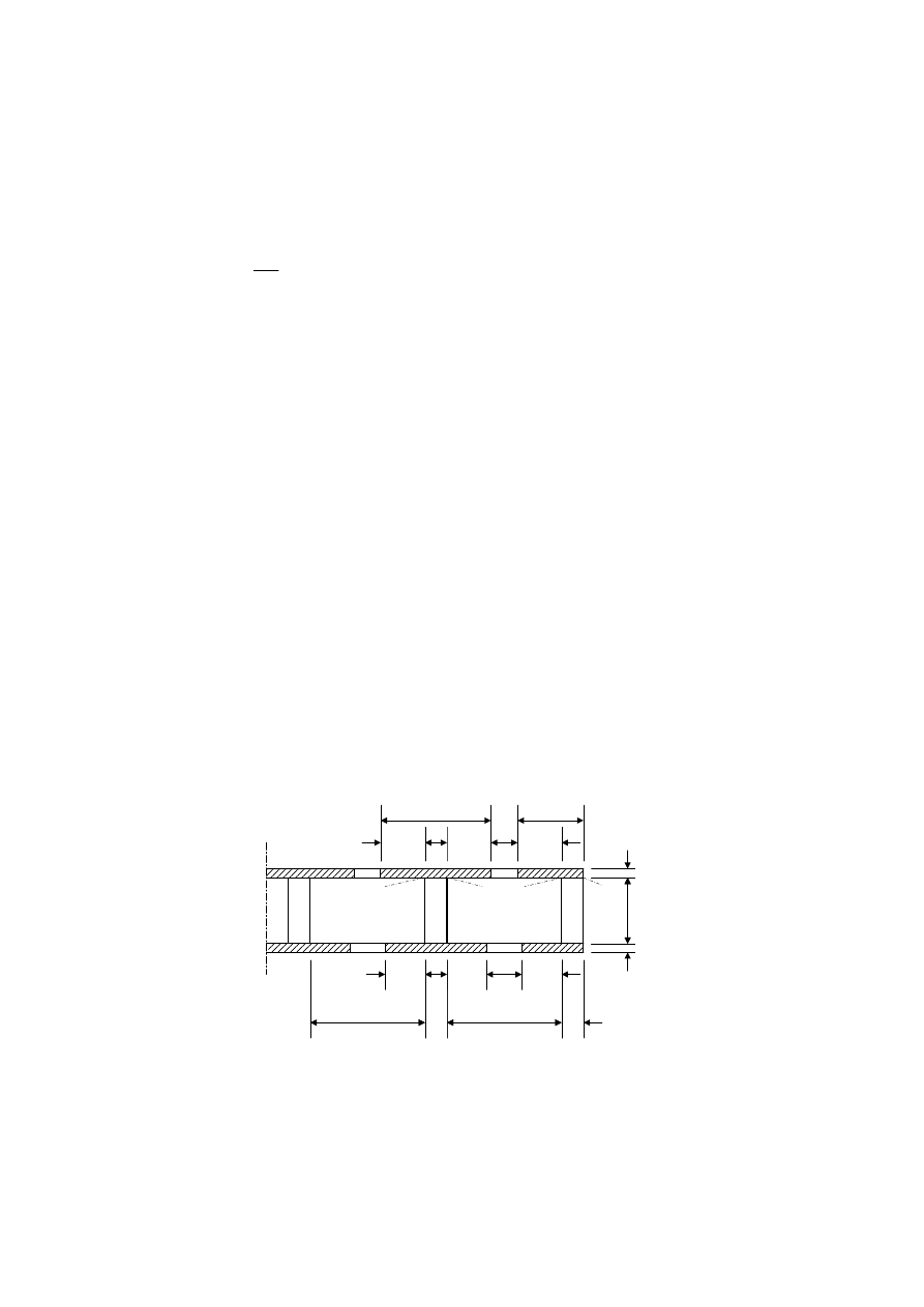
prEN 1995-1-1:2003 (E)
92
greater than twice the effective flange width due to plate buckling, from Table 9.1.
(6) For webs of wood-based panels, it should, for sections 1-1 of an I-shaped cross-section in
Figure 9.2, be verified that:
v,90,d
w
f
mean,d
f
v,90,d
w
f
w
f
b
h
h
f
b
h
b
t
£
ì
ïï
£ í
æ
ö
>
ï
ç
÷
ï
è
ø
î
0,8
for
8
8
for
8
(9.14)
where:
t
mean,d
is the design shear stress at the sections 1-1, assuming a uniform stress distribution;
f
v,90,d
is the design planar (rolling) shear strength of the flange.
For section 1-1 of a U-shaped cross-section, the same expressions should be verified, but with
8h
f
substituted by 4h
f
.
(7) The axial stresses in the flanges, based on the relevant effective flange width, should satisfy
the following expressions:
f,c,d
f,c,d
f
s
£
(9.15)
f,t,d
f,t,d
f
s
£
(9.16)
where:
s
f,c,d
is the mean flange design compressive stress;
s
f,t,d
is the mean flange design tensile stress;
f
f,c,d
is the flange design compressive strength;
f
f,t,d
is the flange design tensile strength.
(8)P It shall be verified that any glued splices have sufficient strength.
(9) The axial stresses in the wood-based webs should satisfy the expressions (9.6) to (9.7)
defined in 9.1.1
h
w
h
f,c
h
f,t
b
w
b
f
b
w
b
f
b
t,ef
/2
b
c,ef
/2
b
ef
b
c,ef
/2
b
c,ef
/2
b
ef
b
t,ef
/2
b
t,ef
/2
1
1
1
1
Figure 9.2 – Thin-flanged beam
9.1.3
Mechanically jointed beams
(1)P If the cross-section of a structural member is composed of several parts connected by
mechanical fasteners, consideration shall be given to the influence of the slip occurring in the

prEN 1995-1-1:2003 (E)
93
joints.
(2) Calculations should be carried out assuming a linear relationship between force and slip.
(3) In order to determine the required fastener spacing in the longitudinal direction, where the
shear force varies between s
min
and s
max
(< 4s
min
), an effective shear force s
ef
may be used as
follows:
ef
min
max
s
s
s
=
+
0,75
0,25
(9.17)
NOTE: A method for the calculation of the load-carrying capacity of mechanically jointed beams is given in
Annex B (Informative).
9.1.4
Mechanically jointed and glued columns
(1)P Deformations due to slip in joints, to shear and bending in packs, gussets, shafts and
flanges, and to axial forces in the lattice shall be taken into account in the strength verification.
NOTE: A method for the calculation of the load-carrying capacity of I- and box-columns, spaced columns
and lattice columns is given in Annex C (Informative).
9.2 Assemblies
9.2.1 Trusses
(1) For trusses which are loaded predominantly at the nodes, the sum of the combined bending
and axial compressive stress ratios given in expressions (6.19) and (6.20) should be limited to
0,9.
(2) For members in compression, the effective column length for in-plane strength verification
should generally be taken as the distance between two adjacent points of contraflexure.
(3) For fully triangulated trusses, the effective column length for members in compression
should be taken as the bay length, see Figure 5.1, if:
- members are only one bay long, without rigid end connections,
- members are continuous over two or more bays and are not loaded laterally
(4) When a simplified analysis of a fully triangulated truss with punched metal plate fasteners
according to clause 5.4.3 has been carried out, the following effective column lengths may be
assumed (see Figure 9.3)
- for continuous members without significant end moments and where the bending stresses of
the lateral load are at least 40 % of the compressive stresses:
- in an outer bay: 0,8 times the bay length;
- in an inner bay: 0,6 the bay length;
- at a node:
0,6 times the largest adjacent bay length;
- for continuous members with significant end moments where the bending stresses of the
lateral load are at least 40 % of the compressive stresses:
- at the beam end with moment: 0,0 (i.e. no column effect);
- in the penultimate bay:
1,0 times bay length;
- remaining bays and nodes:
as described above for continuous beams without
significant end moments;
- for all other cases 1,0 times bay length.
For the strength verification of members in compression and connections, the calculated axial
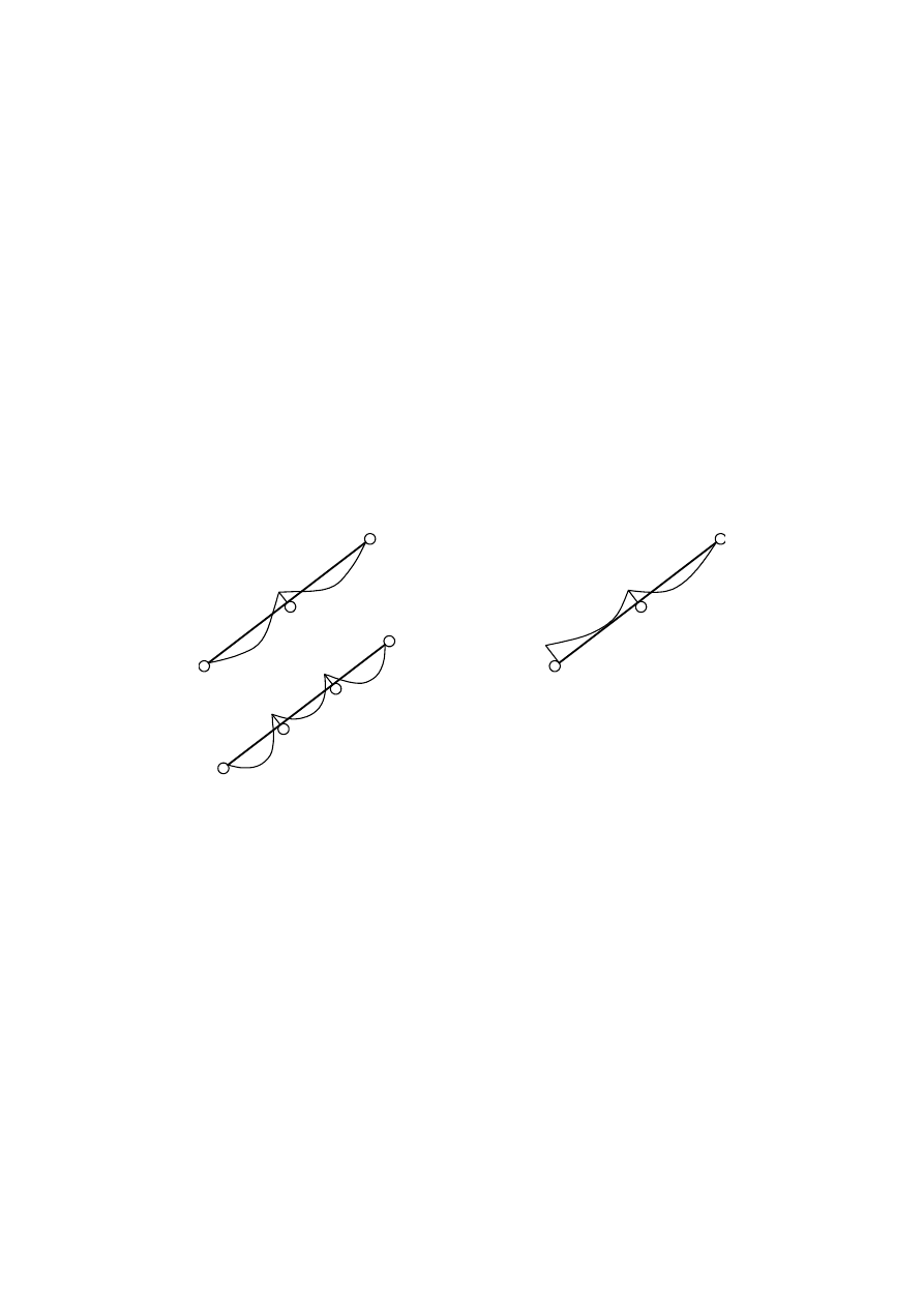
prEN 1995-1-1:2003 (E)
94
forces should be increased by 10 %.
(5) When a simplified analysis is carried out for trusses which are loaded at the nodes, the
tensile and compressive stress ratios as well as the connection capacity should be limited to
70 %.
(6)P A check shall be made that the lateral (out-of-plane) stability of the truss members is
adequate.
(7)P The joints shall be capable of transferring the forces which may occur during handling and
erection.
(8) All joints should be capable of transferring a force F
r,d
acting in any direction within the plane
of the truss. F
r,d
should be assumed to be of short-term duration, acting on timber in service
class 2, with the value:
r,d
F
L
=
+
1,0
0,1
(9.18)
where:
F
r,d
is in kN;
L
is the overall length of the truss, in m.
(a)
(b)
0,8
0,8
0,8
0,8
0,8
0,6
0,6
0,6
0,6
0,6
0,0
1,0
Figure 9.3 – Moment diagrams and effective lengths in compression (a) No significant
end moments (b) Significant end moments
9.2.2
Trusses with punched metal plate fasteners
(1)P Trusses made with punched metal plate fasteners shall conform to the requirements of EN
14250.
(2) The requirements of 5.4.1 and 9.2.1 apply.
(3) For fully triangulated trusses where a small concentrated force (e.g. a man load) has a
component perpendicular to the member of < 1,5kN, and where
s
c,d
< 0,4 f
c,d
, and
s
t,d
< 0,4 f
t,d
,
then the requirements of 6.2.3 and 6.2.4 may be replaced by:
m,d
m,d
0,75 f
s
£
(9.19)
(4) The minimum overlap of the punched metal plate on any timber member should be at least
equal to 40 mm or one third of the height of the timber member, whichever is the greater.
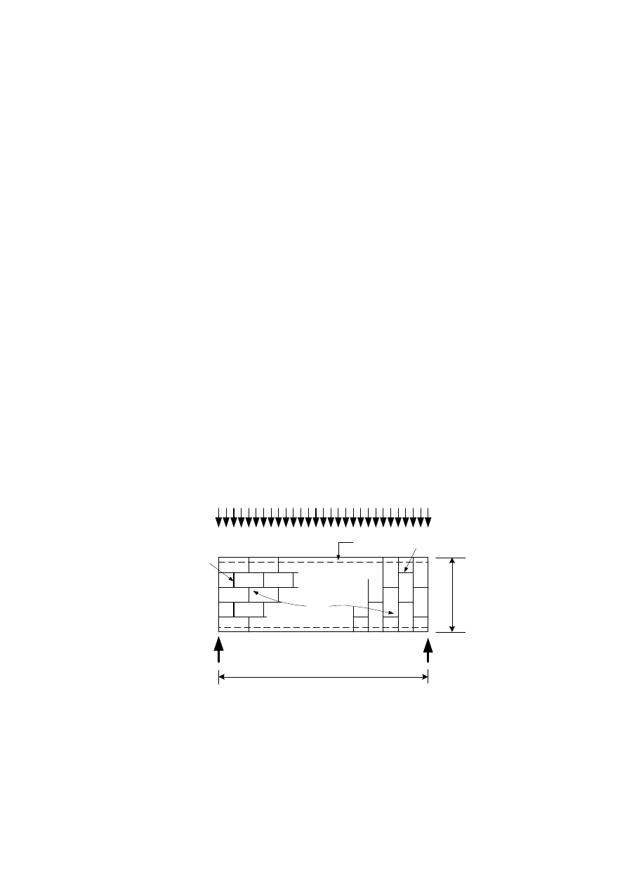
prEN 1995-1-1:2003 (E)
95
(5) Punched metal plate fasteners used in chord splices should cover at least 2/3 of the required
member height.
9.2.3
Roof and floor diaphragms
9.2.3.1 General
(1) This section relates to simply supported diaphragms, such as floors or roofs, assembled
from sheets of wood-based material fixed by mechanical fasteners to a timber frame.
(2) The load-carrying capacity of fasteners at sheet edges may be increased by a factor of 1,2
over the values given in Section 8.
9.2.3.2
Simplified analysis of roof and floor diaphragms.
(1) For diaphragms with a uniformly distributed load (see Figure 9.4) the simplified method of
analysis described in this section should be used provided that:
- the span l lies between 2
b
and 6
b
, where
b
is the diaphragm width;
- the critical ultimate design condition is failure in the fasteners (and not in the panels);
- the panels are fixed in accordance with the detailing rules in 10.8.1.
(2) Unless a more detailed analysis is made, the edge beams should be designed to resist the
maximum bending moment in the diaphragm.
(3) The shear forces in the diaphragm should be assumed to be uniformly distributed over the
width of the diaphragm.
(4) When the sheets are staggered, (see Figure 9.4), the nail spacings along the discontinuous
panel edges may be increased by a factor of 1,5 (up to a maximum of 150 mm) without
reduction of the load-carrying capacity.
(1)
(2)
(2)
b
(3)
l
Key:
(1) Edge beam
(2) Discontinuous edges
(3) Panel arrangements
Figure 9.4 – Diaphragm loading and staggered panel arrangements

prEN 1995-1-1:2003 (E)
96
9.2.4 Wall
diaphragms
9.2.4.1 General
(1)P Wall diaphragms shall be designed to resist both horizontal and vertical actions imposed
upon them.
(2)P The wall shall be adequately restrained to avoid overturning and sliding.
(3)P Wall diaphragms deemed to provide resistance to racking shall be stiffened in-plane by
board materials, diagonal bracing or moment connections.
(4)P The racking resistance of a wall shall be determined either by test according to EN 594 or
by calculations, employing appropriate analytical methods or design models.
(5)P The design of wall diaphragms shall take account of both the material construction and
geometric make-up of the wall under consideration.
(6)P The response of wall diaphragms to actions shall be assessed to ensure the construction
remains within appropriate serviceability limits.
(7) For wall diaphragms two alternative simplified methods of calculation are given in 9.2.4.2
and 9.2.4.3.
NOTE: The recommended procedure is method A given in 9.2.4.2. National choice may be given in the
National annex.
9.2.4.2
Simplified analysis of wall diaphragms – Method A
(1) The simplified method given in this subclause should only be applied to wall diaphragms
with a tie-down at their end, that is the vertical member at the end is directly connected to the
construction below.
(2) The design load-carrying capacity
F
v,Rd
(the design racking resistance) under a force
F
v,Ed
acting at the top of a cantilevered panel secured against uplift (by vertical actions or by
anchoring) should be determined using the following simplified method of analysis for walls
made up of one or more panels, where each wall panel consists of a sheet fixed to one side of a
timber frame, provided that:
- the spacing of fasteners is constant along the perimeter of every sheet;
- the width of each sheet is at least
h
/4.
(3) For a wall made up of several wall panels, the design racking load-carrying capacity of a wall
should be calculated from
v,Rd
i,v,Rd
F
F
=
å
(9.20)
where F
i,v,Rd
is the design racking load-carrying capacity of the wall panel in accordance with
9.2.4.2(3) and 9.2.4.2(5).
(4) The design racking load-carrying capacity of each wall panel, F
i,v,Rd
, against a force F
i,v,Ed
according to Figure 9.5 should be calculated from
f,Rd
i i
i,v,Rd
F
b c
F
s
=
(9.21)
where:
F
f,Rd
is the lateral design capacity of an individual fastener;
b
i
is the wall panel width;
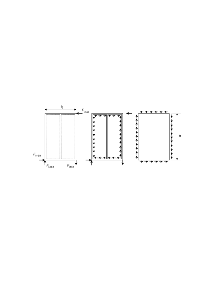
prEN 1995-1-1:2003 (E)
97
s
is the fastener spacing.
and
i
i
i
i
b
b
c
b
b
b
b
³
ì
ï
= í
<
ï
î
0
0
0
1
for
for
(9.22)
where:
b
0
= h/2
h is the height of the wall.
(5) For fasteners along the edges of an individual sheet, the design lateral load-carrying
capacity should be increased by a factor of 1,2 over the corresponding values given in Section
8. In determining the fastener spacing in accordance with the requirements of Section 8, the
edges should be assumed to be unloaded.
a)
b)
c)
Figure 9.5 – Forces acting on:
a) wall panel;
b) framing;
c) sheet
(6) Wall panels which contain a door or window opening should not be considered to contribute
to the racking load-carrying capacity.
(7) For wall panels with sheets on both sides the following rules apply:
-
if the sheets and fasteners are of the same type and dimension then the total racking load-
carrying capacity of the wall should be taken as the sum of the racking load-carrying
capacities of the individual sides
-
if different types of sheets are used, 75 % of the racking load-carrying capacity of the weaker
side may, unless some other value is shown to be valid, be taken into consideration if
fasteners with similar slip moduli are used. In other cases not more than 50 % should be
taken into consideration.
(8) The external forces F
i,c,Ed
and F
i,t,Ed
according to Figure 9.5 should be determined from
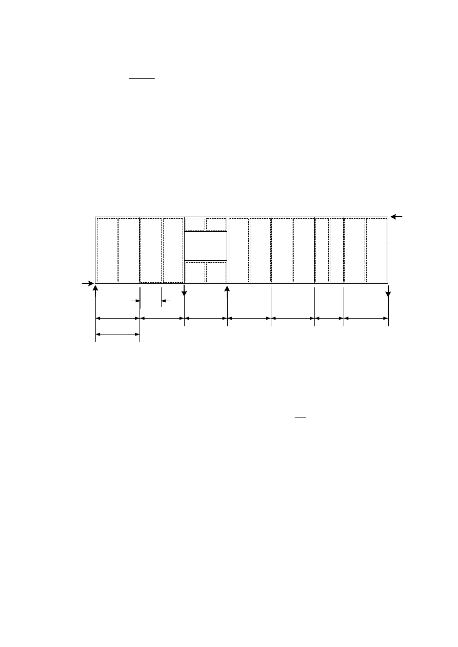
prEN 1995-1-1:2003 (E)
98
i,v,Ed
i,c,Ed
i,t,Ed
i
F
h
F
F
b
=
=
(9.23)
where
h
is the height of the wall.
(9) These forces can either be transmitted to the sheets in the adjacent wall panel or transmitted
to the construction situated above or below. When tensile forces are transmitted to the
construction situated below, the panel should be anchored by stiff fasteners. Buckling of wall
studs should be checked in accordance with 6.3.2. Where the ends of vertical members bear on
horizontal framing members, the compression perpendicular to the grain stresses in the
horizontal members should be assessed according to 6.1.5.
(10) The external forces which arise in wall panels containing door or window openings and in
wall panels of smaller width, see Figure 9.6, can similarly be transmitted to the construction
situated above or below.
F
v,Ed
F
v,Ed
b
net
(1)
(1)
(2)
(1)
(1)
(3)
(1)
b
i
Key:
(1) Wall panel (normal width)
(2) Wall panel with window
(3) Wall panel (smaller width)
Figure 9.6 – Example of the assembly of wall panels containing a wall panel with a
window opening and a wall panel of smaller width
(11) Shear buckling of the sheet may be disregarded, provided that
net
b
t
£ 100
where:
b
net
is the clear distance between studs;
t
is the thickness of the sheet.
(12) In order that the centre stud may be considered to constitute a support for a sheet, the
spacing of fasteners in the centre stud should not be greater than twice the spacing of the
fasteners along the edges of the sheet.
(13) Where each panel consists of a prefabricated wall element, the transfer of shear forces
between the separate wall elements should be verified.
(14) In contact areas between vertical studs and horizontal timber members, compression
stresses perpendicular to grain should be verified in the timber members.
prEN 1995-1-1:2003 (E)
99
9.2.4.3
Simplified analysis of wall diaphragms – Method B
9.2.4.3.1
Construction of walls and panels to meet the requirements of the simplified
analysis
(1) A wall assembly (see Figure 9.7) is comprised of one or more walls with each wall formed
from one or more panels, the panels being made from sheets of wood-based panel products,
such as those described in 3.5, fastened to a timber frame.
(10)
(11)
(12)
(13)
(1)
(2)
(4)
(5)
(6)
(7)
(8)
(9)
(3)
Key:
(1) Wall panel 1
(2) Wall panel 2
(3) Wall panel 3
(4) Wall panel 4
(5) Wall panel 5
(6) Wall 1
(7) Wall 2
(8) Wall 3
(9) Wall assembly
(10) Sheet
(11) Head binder
(12) Window
(13) Door
Figure 9.7 – Example of wall assembly consisting of several wall panels
(2) For a panel to contribute to the in-plane (racking) strength of a wall the width of the panel
should be at least the panel height divided by 4. The fastening of the sheets to the timber frame
should be by either nails or screws and the fasteners should be equally spaced around the
perimeter of the sheet. Fasteners within the perimeter of a sheet should be spaced at not more
than twice the perimeter fastener spacing.
(3) Where an opening is formed in a panel, the lengths of panel on each side of the opening
should be considered as separate panels.
(4) Where panels are combined to form a wall:
- the tops of individual panels should be linked by a member or construction across the panel
joints;
- the required vertical connection strength between two panels should be evaluated but should
have a design strength of at least 2,5 kN/m;
- the panels when joined together to form a wall should be able to resist overturning and
sliding forces by either anchorage to the supporting structure or the permanent actions
applied to the wall or a combination of both effects.

prEN 1995-1-1:2003 (E)
100
9.2.4.3.2 Design
procedure
(1) The in-plane design shear (racking) strength F
v,Rd
against a force F
v,Ed
acting at the top of a
cantilevered wall that is secured against uplift and sliding by vertical actions and/or anchorage,
should be determined using the following simplified method for the wall construction defined in
9.2.4.3.1.
(2) For a wall assembly made up of several walls, the design racking strength of the wall
assembly F
v,Rd
should be calculated from
v,Rd
i,v,Rd
F
F
=
å
(9.24)
where:
F
i,v,Rd
is the design racking strength of a wall in accordance with (3) below.
(3) The design racking strength of a wall i, F
i,v,Rd
, should be calculated from
f,Rd
i
i,v,Rd
d
i,q
s
n
0
F
b
F
k k k k
s
=
(9.25)
where:
F
f,Rd
is the lateral design capacity of an individual fastener;
b
i
is the wall length, in m;
s
0
is the basic fastener spacing, see (4) below;
k
d
is the dimension factor for the panel, see (4) below;
k
i,q
is the uniformly distributed load factor for wall i, see (4) below;
k
s
is the fastener spacing factor, see (4) below;
k
n
is the sheathing material factor, see (4) below.
(4) The values of s
0,
k
d
, k
i,q
, k
s
and k
n
should be calculated as:
-
0
k
d
s
r
=
9700
(9.26)
where:
d is the fastener diameter, in mm;
r
k
is the characteristic density of the timber frame;
-
i
i
i
i
d
i
i
i
b
b
h
h
b
b
k
b
h
h
b
b
h
h
ì
£
ï
ï
ïæ ö
ï
=
>
£
íç ÷
è ø
ï
ï
æ
ö
ï
>
>
ç
÷
ïè
ø
î
0,4
0,4
for 1,0
(a)
for
1,0 and
4,8 m
(b)
4,8
for
1,0 and
4,8 m
(c)
(9.27)
where h is the height of the wall, in m;
-
(
)
i,q
i
i
i
k
q
q
b
æ
ö
= +
-
ç
÷
è
ø
0,4
2
2,4
1
0,083
0,0008
(9.28)
where q
i
is the equivalent uniformly distributed vertical load acting on the wall, in kN/m, with
q
i
³ 0, see (5) below;
prEN 1995-1-1:2003 (E)
101
-
s
0
k
s
s
=
+
1
0,86
0,57
(9.29)
where s is the spacing of the fasteners around the perimeter of the sheets;
-
i,v,Rd,max
i,v,Rd,min
n
i,v,Rd,max
F
F
k
F
ì
ï
+
= í
ï
î
1,0
for sheathing on one side
(a)
0,5
for sheathing on both sides
(b)
(9.30)
where:
F
i,v,Rd,max
is the design racking strength of the stronger sheathing;
F
i,v,Rd,min
is the design racking strength of the weaker sheathing.
(5) The equivalent vertical load, q
i
, used to calculate k
i,q
should be determined using only
permanent actions and any net effects of wind together with the equivalent actions arising from
concentrated forces, including anchorage forces, acting on the panel. For the purposes of
calculating k
i,q
, concentrated vertical forces should be converted into an equivalent uniformly
distributed load on the assumption that the wall is a rigid body e.g. for the load F
i,vertEd
acting on
the wall as shown in Figure 9.8
i,vert,Ed
i
2
i
2
a F
q
b
=
(9.31)
where:
a is the horizontal distance from the force F to the leeward corner of the wall;
b is the length of the wall.
F
i,t,Ed
F
i,c,Ed
F
i,v,Ed
F
i,vert,Ed
a
b
i
q
i
F
i,v,Ed
F
i,q,Ed
F
i,q,Ed
Figure 9.8 – Determination of equivalent vertical action q
i
and reaction forces from
vertical and horizontal actions

prEN 1995-1-1:2003 (E)
102
(6) The external forces F
i,c,Ed
and
F
i,t,Ed
(see Figure 9.8) from the horizontal action
F
i,v,Ed
on wall
i
should be determined from
i,v,Ed
i,c,Ed
i,t,Ed
i
F
h
F
F
b
=
=
(9.32)
where h is the height of the wall.
These external forces can be transmitted to either the adjacent panel through the vertical panel-
to-panel connection or to the construction above or below the wall. When tensile forces are
transmitted to the construction below, the panel should be anchored with stiff fasteners.
Compression forces in the vertical members should be checked for buckling in accordance with
6.3.2. Where the ends of vertical members bear on horizontal framing members, the
compression perpendicular to the grain stresses in the horizontal members should be assessed
according to 6.1.5.
(7) The buckling of the sheets under the action of shear force F
v,Ed
may be disregarded provided
net
b
t
£ 100
(9.33)
where:
b
net
is the clear distance between vertical members of the timber frame;
t
is the thickness of the sheathing.
9.2.5 Bracing
9.2.5.1 General
(1)P Structures which are not otherwise adequately stiff shall be braced to prevent instability or
excessive deflection.
(2)P The stress caused by geometrical and structural imperfections, and by induced deflections
(including the contribution of any joint slip) shall be taken into account.
(3)P The bracing forces shall be determined on the basis of the most unfavourable combination
of structural imperfections and induced deflections.
9.2.5.2
Single members in compression
(1) For single elements in compression, requiring lateral support at intervals a (see Figure 9.9),
the initial deviations from straightness between supports should be within a/500 for glued
laminated or LVL members, and a/300 for other members.
(2) Each intermediate support should have a minimum spring stiffness C
d
s
=
N
C
k
a
(9.34)
where:
k
s
is a modification factor;
N
d
is the mean design compressive force in the element;
a
is the bay length (see Figure 9.9).
NOTE: For k
s
, see note in 9.2.5.3(1)
prEN 1995-1-1:2003 (E)
103
(3) The design stabilizing force F
d
at each support should be taken as:
d
f,1
d
d
f,2
N
k
F
N
k
ì
ï
ï
= í
ï
ïî
for solid timber
for glued laminated timber andLVL
(9.35)
where k
f,1
and k
f,2
are modification factors.
NOTE: For k
f,1
and k
f,2
, see note in 9.2.5.3(1)
N
N
C
a
m = 2
m = 4
N
a
N
C
C
C
Figure 9.9 – Examples of single members in compression braced by lateral supports.
(4) The design stabilizing force
F
d
for the compressive edge of a rectangular beam should be
determined in accordance with 9.2.5.2(3)
where:
(
)
d
d
crit
M
N
k
h
=
1-
(9.36)
The value of k
crit
should be determined from 6.3.3(4) for the unbraced beam, and M
d
is the
maximum design moment acting on the beam of depth h.
9.2.5.3
Bracing of beam or truss systems
(1) For a series of
n
parallel members which require lateral supports at intermediate nodes A,B,
etc. (see Figure 9.10) a bracing system should be provided, which, in addition to the effects of
external horizontal load (e.g. wind), should be capable of resisting an internal stability load per
unit length
q
, as follows:
d
d
f,3
nN
q
k
k
=
l
l
(9.37)
where:
k
ì
ï
=
í
ï
î
l
l
1
min
15
(9.38)
N
d
is the mean design compressive force in the member;
prEN 1995-1-1:2003 (E)
104
l
is the overall span of the stabilizing system, in m;
k
f,3
is a modification factor.
l
A
B
a
a
a
(1)
(2)
(5)
(3)
(6)
N
N
N
(4)
(7)
Key:
(1)
n
members of truss system
(2) Bracing
(3) Deflection of truss system due to imperfections and second order effects
(4) Stabilizing forces
(5) External load on bracing
(6) Reaction forces of bracing due to external loads
(7) Reaction forces of truss system due to stabilizing forces
Figure 9.10 – Beam or truss system requiring lateral supports
NOTE: The values of the modification factors k
s
, k
f,1
, k
f,2
and k
f,3
depend on influences such as
workmanship, span etc. Ranges of values are given in Table 9.2 where the recommended values are
underlined. The National choice may be given in the National annex.
Table 9.2 – Recommended values of modification factors
Modification factor
Range
k
s
4 to 1
k
f,1
50 to 80
k
f,2
80 to 100
k
f,3
30 to 80
(2) The horizontal deflection of the bracing system due to force q
d
and any other external load
(e.g. wind), should not exceed
l
/500.

prEN 1995-1-1:2003 (E)
105
Section 10 Structural detailing and control
10.1 General
(1)P The provisions given in this section are prerequisite requirements for the design rules given
in this standard to apply.
10.2 Materials
(1) The deviation from straightness measured midway between the supports should, for
columns and beams where lateral instability can occur, or members in frames, be limited to
1/500 times the length of glued laminated timber or LVL members and to 1/300 times the length
of solid timber. The limitations on bow in most strength grading rules are inadequate for the
selection of material for these members and particular attention should therefore be paid to their
straightness.
(2) Timber and wood-based components and structural elements should not be unnecessarily
exposed to climatic conditions more severe than those expected in the finished structure.
(3) Before being used in construction, timber should be dried as near as practicable to the
moisture content appropriate to its climatic condition in the completed structure. If the effects of
any shrinkage are not considered important, or if parts that are unacceptably damaged are
replaced, higher moisture contents may be accepted during erection provided that it is ensured
that the timber can dry to the desired moisture content.
10.3 Glued
joints
(1) Where bond strength is a requirement for ultimate limit state design, the manufacture of
glued joints should be subject to quality control, to ensure that the reliability and quality of the
joint is in accordance with the technical specification.
(2) The adhesive manufacturer’s recommendations with respect to mixing, environmental
conditions for application and curing, moisture content of members and all factors relevant to
the proper use of the adhesive should be followed.
(3) For adhesives which require a conditioning period after initial set, before attaining full
strength, the application of load to the joint should be restricted for the necessary time.
10.4
Connections with mechanical fasteners
10.4.1 General
(1)P Wane, splits, knots or other defects shall be limited in the region of the connection such
that the load-carrying capacity of the connection is not reduced.
10.4.2 Nails
(1) Unless otherwise specified, nails should be driven in at right angles to the grain and to such
depth that the surfaces of the nail heads are flush with the timber surface.
(2) Unless otherwise specified, slant nailing should be carried out in accordance with Figure
8.8(b).
(3) The diameter of pre-drilled holes should not exceed 0,8
d
, where
d
is the nail diameter.
10.4.3 Bolts and washers
(1) Bolt holes in timber should have a diameter not more than 1 mm larger than the bolt. Bolt
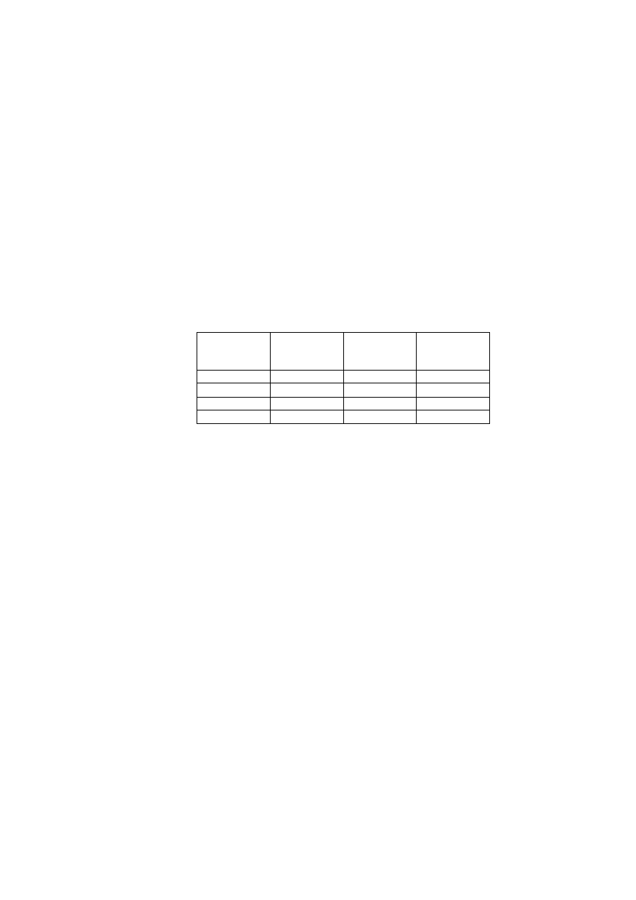
prEN 1995-1-1:2003 (E)
106
holes in steel plates should have a diameter not more than 2 mm or 0,1
d
(whichever is the
greater) larger than the bolt diameter d.
(2) Washers with a side length or a diameter of at least 3
d
and a thickness of at least 0,3
d
should be used under the head and nut. Washers should have a full bearing area.
(3) Bolts and lag screws should be tightened so that the members fit closely, and they should be
re-tightened if necessary when the timber has reached equilibrium moisture content to ensure
that the load-carrying capacity and stiffness of the structure is maintained.
(4) The minimum diameter requirements given in Table 10.1 apply to bolts used with timber
connectors, where:
d
c
is the connector diameter, in mm;
d
is the bolt diameter, in mm
d
1
is the diameter of centre hole of connector.
Table 10.1 – Requirements for diameters of bolts used with timber connectors
Type of
connector
EN 912
d
c
d
minimum
d
maximum
mm mm mm
A1 – A6
£
130
12 24
A1, A4, A6
> 130
0,1 d
c
24
B d
1
-1
d
1
10.4.4 Dowels
(1) The minimum dowel diameter should be 6 mm. The tolerances on the dowel diameter
should be - 0/+0,1 mm. Pre-bored holes in the timber members should have a diameter not
greater than the dowel.
10.4.5 Screws
(1) For screws in softwoods with a smooth shank diameter d ≤ 6 mm, pre-drilling is not required.
For all screws in hardwoods and for screws in softwoods with a diameter d
³
6 mm, pre-drilling
is required, with the following requirements:
-
The lead hole for the shank should have the same diameter as the shank and the same
depth as the length of the shank
-
The lead hole for the threaded portion should have a diameter of approximately 70 % of the
shank diameter.
(2) For timber densities greater than 500 kg/m
3
, the pre-drilling diameter should be determined
by tests.
10.5 Assembly
(1) The structure should be assembled in such a way that over-stressing of its members or
connections is avoided. Members which are warped, split or badly fitting at the joints should be
replaced.
10.6
Transportation and erection
(1) The over-stressing of members during storage, transportation or erection should be avoided.
If the structure is loaded or supported in a different manner during construction than in the
finished building the temporary condition should be considered as a relevant load case,

prEN 1995-1-1:2003 (E)
107
including any possible dynamic actions. In the case of structural framework, e.g. framed arches,
portal frames, special care should be taken to avoid distortion during hoisting from the
horizontal to the vertical position.
10.7 Control
(1) It is assumed that a control plan comprises:
-
production and workmanship control off and on site;
-
control after completion of the structure.
NOTE 1: The control of the construction is assumed to include:
- preliminary tests, e.g. tests for suitability of materials and production methods;
- checking of materials and their identification e.g.:
- for wood and wood-based materials: species, grade, marking, treatments and moisture content;
- for glued constructions: adhesive type, production process, glue-line quality;
- for fasteners: type, corrosive protection;
- transport, site storage and handling of materials;
- checking of correct dimensions and geometry;
- checking of assembly and erection;
- checking of structural details, e.g.:
- number of nails, bolts etc.;
- sizes of holes, correct pre-drilling;
- spacings and distances to end and edge of members;
- splitting;
- final checking of the result of the production process, e.g. by visual inspection or proof loading.
NOTE 2: A control program is assumed to specify the control measures (inspection maintenance) to be
carried out in service where long-term compliance with the basic assumptions for the project is not
adequately ensured.
NOTE 3: All the information required for the use in service and the maintenance of a structure is assumed
to be made available to the person or authority who undertakes responsibility for the finished structure.
10.8
Special rules for diaphragm structures
10.8.1 Floor and roof diaphragms
(1) The simplified method of analysis given in 9.2.3.2 assumes that sheathing panels not
supported by joists or rafters are connected to each other e.g. by means of battens as shown in
Figure 10.1. Nails other than smooth nails, as defined in EN 14592, or screws should be used,
with a maximum spacing along the edges of the sheathing panels of 150 mm. Elsewhere the
maximum spacing should be 300 mm.
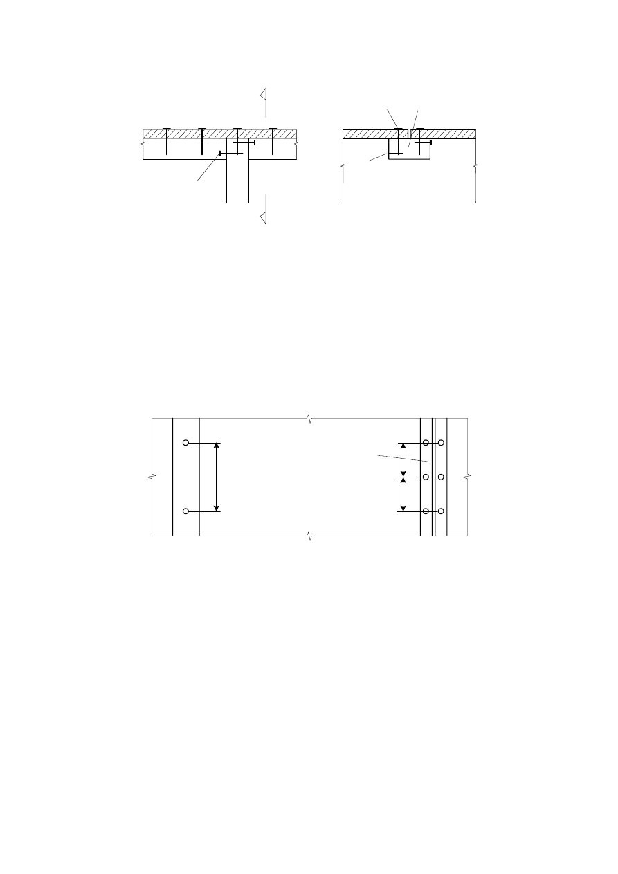
prEN 1995-1-1:2003 (E)
108
A
A
(1)
(2)
(3)
A
¾ A
(1)
Key:
(1) Batten slant nailed to joist or rafter
(2) Batten
(3) Sheathing nailed to batten
Figure 10.1 – Example of connection of panels not supported by a joist or a rafter
10.8.2 Wall
diaphragms
(1) The simplified methods of analysis given in 9.2.4.2 and 9.2.4.3 assume that panel fixings
have a maximum fastener spacing along the edges of 150 mm for nails, and 200 mm for
screws. On internal studs the maximum spacing should be no more than twice the spacing
along the edge or 300 mm, whichever is the lesser. See Figure 10.2.
(1)
(2)
(3)
Key:
(1) Maximum nail spacing 300 mm to intermediate studs
(2) Panel edge
(3) Maximum nail spacing 150 mm
Figure 10.2 – Panel fixings
10.9
Special rules for trusses with punched metal plate fasteners
10.9.1 Fabrication
(1) Trusses should be fabricated in accordance with EN 14250.
10.9.2 Erection
(1) Trusses should be checked for straightness and vertical alignment prior to fixing the
permanent bracing.

prEN 1995-1-1:2003 (E)
109
(2) When trusses are fabricated, the members should be free from distortion within the limits
given in EN 14250. However, if members which have distorted during the period between
fabrication and erection can be straightened without damage to the timber or the joints and
maintained straight, the truss may be considered satisfactory for use.
(3) The maximum bow a
bow
in any truss member after erection should be limited. Provided that it
is adequately secured in the completed roof to prevent the bow from increasing, the permitted
value of the maximum bow should be taken as a
bow,perm
.
Note: The recommended range of a
bow,perm
is 10 to 50 mm. The National choice may be given in the
National annex.
(4) The maximum deviation a
dev
of a truss from true vertical alignment after erection should be
limited. The permitted value of the maximum deviation from true vertical alignment should be
taken as a
dev,perm
.
Note: The recommended range of a
dev,perm
is 10 to 50 mm. The National choice may be given in the
National annex.

prEN 1995-1-1:2003 (E)
110
Annex A (Informative): Block shear and plug shear failure at multiple
dowel-type steel-to-timber connections
(1) For steel-to-timber connections comprising multiple dowel-type fasteners subjected to a
force component parallel to grain near the end of the timber member, the characteristic load-
carrying capacity of fracture along the perimeter of the fastener area, as shown in Figure A.1
(block shear failure) and Figure A.2 (plug shear failure), should be taken as:
net,t t,o,k
bs,Rk
net,v v,k
A
f
F
A
f
ìï
=
í
ïî
1,5
max
0,7
(A.1)
with
net,t
net,t 1
A
L
t
=
(A.2)
(
)
net,v
net,v
net,v
net,t
L
t
A
L
L
t
ì
ï
= í
+
ïî
1
ef
failuremodes (e,f, j/l, k, m)
2
allother failuremodes
2
(A.3)
and
net,v
v,i
i
L
l
=
å
(A.4)
net,t
t,i
i
L
l
=
å
(A.5)
-
for thin steel plates (for failure modes given in brackets)
ef
y,Rk
h,k
t
t
M
f
d
ì
ï
= í
ï
î
1
0,4
(a)
1,4
(b)
(A.6)
-
for thick steel plates (for failure modes given in brackets)
y,Rk
h,k
ef
y,Rk
h,k
M
f
d
t
M
t
f d t
ì
ï
ïï
= í
é
ù
ï ê +
- ú
ï ê
ú
ï ë
û
î
1
2
1
2
(d)(h)
2
1
(c)(g)
(A.7)
where
F
bs,Rk
is the characteristic block shear or plug shear capacity;
A
net,t
is the net cross-sectional area perpendicular to the grain;
A
net,v
is the net shear area in the parallel to grain direction;
L
net,t
is the net width of the cross-section perpendicular to the grain;
L
net,v
is the total net length of the shear fracture area;
l
v,i
,
l
t,i
are defined in figure A.1;
t
ef
is the effective depth depending of the failure mode of the fastener, see Figure 8.3;
t
1
is the timber member thickness or penetration depth of the fastener;
M
y,Rk
is the characteristic yield moment of the fastener;
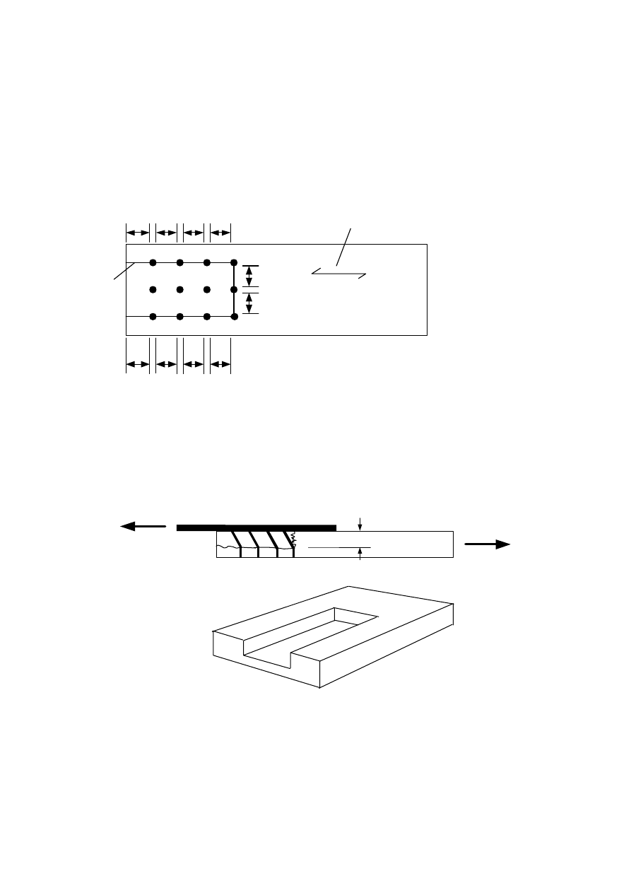
prEN 1995-1-1:2003 (E)
111
d
is the fastener diameter;
f
t,0,k
is the characteristic tensile strength of the timber member;
f
v,k
is the characteristic shear strength of the timber member;
f
h,k
is the characteristic embedding strength of the timber member.
NOTE: The failure modes associated with expressions (A.3), (A.6) and (A.7) are shown in Figure 8.3.
l
t,1
l
t,2
l
v,1
l
v,2
l
v,3
l
v,4
l
v,5
l
v,6
l
v,7
l
v,8
1
2
Key:
1 Grain
direction
2 Fracture
line
Figure A.1 – Example of block shear failure
t
ef
Figure A.2 – Example of plug shear failure

prEN 1995-1-1:2003 (E)
112
Annex B (Informative): Mechanically jointed beams
B.1 Simplified
analysis
B.1.1 Cross-sections
(1) The cross-sections shown in Figure B.1 are considered in this annex.
B.1.2 Assumptions
(1) The design method is based on the theory of linear elasticity and the following assumptions:
-
the beams are simply supported with a span
l
. For continuous beams the expressions may
be used with
l
equal to 0,8 of the relevant span and for cantilevered beams with
l
equal to
twice the cantilever length
-
the individual parts (of wood, wood-based panels) are either full length or made with glued
end joints
-
the individual parts are connected to each other by mechanical fasteners with a slip modulus
K
-
the
spacing
s
between the fasteners is constant or varies uniformly according to the shear
force between s
min
and
s
max
, with s
max
< 4 s
min
-
the load is acting in the z-direction giving a moment M
=
M(x)
varying sinusoidally or
parabolically and a shear force V = V(x
)
.
B.1.3 Spacings
(1) Where a flange consists of two parts jointed to a web or where a web consists of two parts
(as in a box beam), the spacing
s
i
is determined by the sum of the fasteners per unit length in
the two jointing planes.
B.1.4
Deflections resulting from bending moments
(1) Deflections are calculated by using an effective bending stiffness
(
EI)
ef
determined in
accordance with B.2.
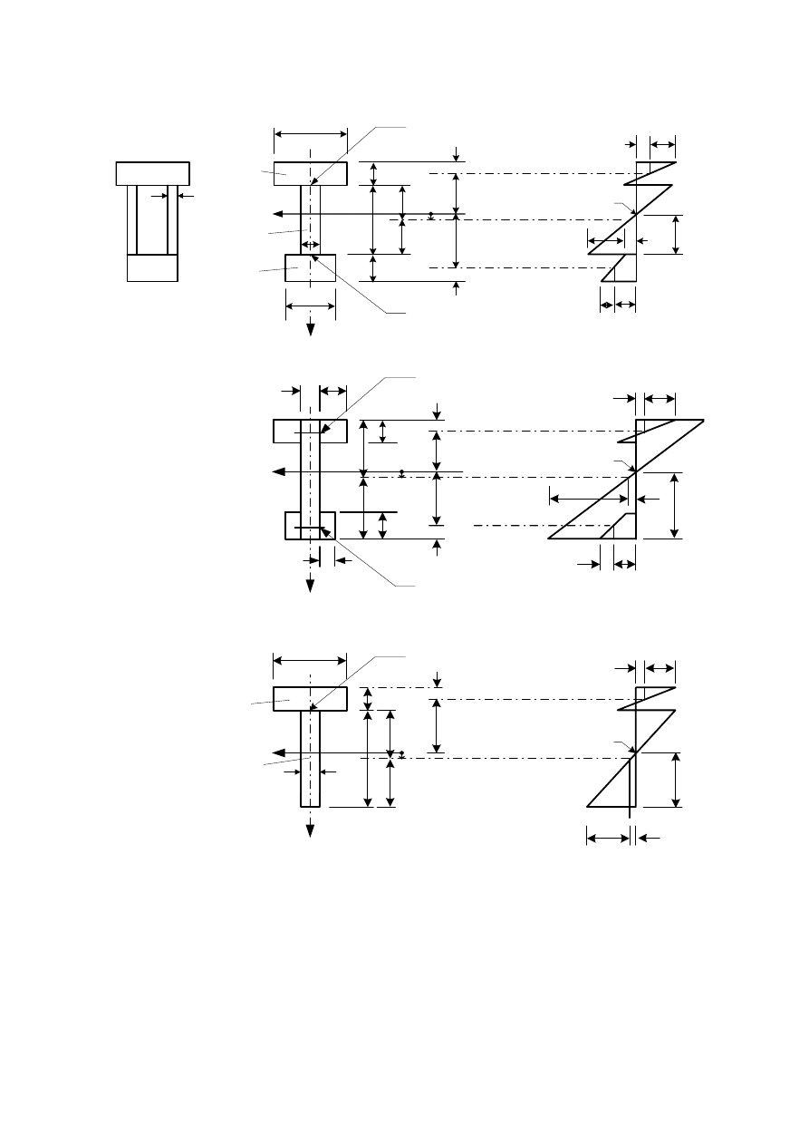
prEN 1995-1-1:2003 (E)
113
A
1
, I
1
, E
1
A
2
, I
2
, E
2
A
3
, I
3
, E
3
z
y
b
3
a
3
a
1
b
1
h
1
h
3
h
2
a
2
0,5h
2
0,5h
2
0,5h
1
0,5h
3
b
2
0,5b
2
h
s
m,2
s
2
t
max
s
3
s
m,3
s
1
s
m,1
(1)
(2)
s
2
(1)
(2)
b
2
0,5h
2
0,5b
1
h
1
0,5h
1
a
1
a
3
a
2
0,5h
2
0,5h
3
h
3
0,5b
3
s
1
s
m,1
t
max
s
m,2
s
3
s
m,3
h
A
1
, I
1
, E
1
A
2
, I
2
, E
2
y
z
z
y
(1)
b
1
h
1
h
2
0,5h
2
0,5h
2
a
2
a
1
0,5h
1
b
2
s
1
s
m,1
h
s
m,2
s
2
t
max
Key:
(1) spacing:
s
1
slip
modulus:
K
1
load:
F
1
(2) spacing:
s
3
slip
modulus:
K
3
load:
F
3
Figure B.1 – Cross-section (left) and distribution of bending stresses (right). All
measurements are positive except for a
2
which is taken as positive as shown.

prEN 1995-1-1:2003 (E)
114
B.2
Effective bending stiffness
(1) The effective bending stiffness should be taken as:
i
ef
i
i
i
i
i
i
E I
I
E A a
E
g
=
=
+
å
3
2
1
(
(
)
)
(B.1)
using mean values of E and where:
i
i i
A
b h
=
(B.2)
i i
i
b h
I
=
3
12
(B.3)
g =
2
1
(B.4)
i
i
i
i
i
i
i
E
s
l
A
K
g
p
é
ù
= +
=
=
ë
û
-1
2
2
1
/(
)
for
1 and 3
(B.5)
i
i
i
i
E A
A
h
h
h
h
E
a
E A
g
g
g
=
+
+
=
S
3
1
2
2
3
1
1
1
3
3
2
3
1
(
) -
(
)
2
(B.6)
where the symbols are defined in Figure B.1;
K
i
= K
ser,i
for the serviceability limit state calculations;
K
i
= K
u,i
for the ultimate limit state calculations.
For T-sections h
3
= 0
B.3 Normal
stresses
(1) The normal stresses should be taken as:
i
i i
i
ef
(
)
E a M
E I
g
s =
(B.7)
i i
m,i
ef
E h M
E I
s
=
0,5
(
)
(B.8)
B.4
Maximum shear stress
(1) The maximum shear stresses occur where the normal stresses are zero. The maximum
shear stresses in the web member (part 2 in Figure B.1) should be taken as:
max
ef
E A a
E b h
V
b E I
g
t
+
=
2
3
3
3 3
2 2 2
2,
2
0,5
(
)
(B.9)
B.5 Fastener
load
(1) The load on a fastener should be taken as:
i
i
i i i
i
ef
(
)
E A a s
F
V
E I
g
=
(B.10)
where:

prEN 1995-1-1:2003 (E)
115
i = 1 and 3, respectively;
s
i
= s
i
(x) is the spacing of the fasteners as defined in B.1.3(1).

prEN 1995-1-1:2003 (E)
116
Annex C (Informative): Built-up columns
C.1 General
C.1.1 Assumptions
(1) The following assumptions apply:
- the columns are simply supported with a length l;
- the individual parts are full length;
- the load is an axial force F
c
acting at the geometric centre of gravity, (see however C.2.3).
C.1.2 Load-carrying
capacity
(1) For column deflection in the y-direction (see Figure C.1 and Figure C.3) the load-carrying
capacity should be taken as the sum of the load-carrying capacities of the individual members.
(2) For column deflection in the z-direction (see Figure C.1 and Figure C.3) it should be verified
that:
c,0,d
c c,0,d
k f
s
£
(C.1)
where:
c,d
c,0,d
tot
F
A
s
=
(C.2)
where:
A
tot
is the total cross-sectional area;
k
c
is determined in accordance with 6.3.2 but with an effective slenderness ratio
l
ef
determined in accordance with sections C.2 - C.4.
C.2 Mechanically
jointed
columns
C.2.1 Effective
slenderness
ratio
(1) The effective slenderness ratio should be taken as:
tot
ef
ef
A
I
l = l
(C.3)
with
ef
ef
mean
(
)
EI
I
E
=
(C.4)
where (EI)
ef
is determined in accordance with Annex B (informative).
C.2.2
Load on fasteners
(1) The load on a fastener should be determined in accordance with Annex B (informative),
where

prEN 1995-1-1:2003 (E)
117
c,d
ef
c
c,d ef
d
ef
c
c,d
ef
c
V
F
k
F
k
F
k
l
l
l
l
=
ì
<
ï
ï
ïï
£
<
í
ï
ï
ï
£
ïî
for
30
120
for
30
60
3600
for 60
60
(C.5)
C.2.3 Combined
loads
(1) In cases where small moments (e.g. from self weight) are acting in adition to axial load,
6.3.2(3)applies.
C.3
Spaced columns with packs or gussets
C.3.1 Assumptions
(1) Columns as shown in Figure C.1 are considered, i.e. columns comprising shafts spaced by
packs or gussets. The joints may be either nailed or glued or bolted with suitable connectors.
(2) The following assumptions apply:
-
the cross-section is composed of two, three or four identical shafts;
-
the cross-sections are symmetrical about both axes;
-
the number of unrestrained bays is at least three, i.e. the shafts are at least connected at the
ends and at the third points;
-
the free distance
a
between the shafts is not greater than three times the shaft thickness
h
for columns with packs and not greater than 6 times the shaft thickness for columns with
gussets;
-
the joints, packs and gussets are designed in accordance with C.2.2;
-
the pack length
l
2
satisfies the condition:
l
2
/
a
³
1,5;
-
there are at least four nails or two bolts with connectors in each shear plane. For nailed joints
there are at least four nails in a row at each end in the longitudinal direction of the column;
-
the gussets satisfies the condition:
l
2
/
a
³
2;
-
the columns are subjected to concentric axial loads.
(3) For columns with two shafts A
tot
and I
tot
should be calculated as
tot
A
A
=
2
(C.6)
(
)
tot
b
h a
a
I
é
ù
+
-
ê
ú
ë
û
=
3
3
2
12
(C.7)
(4) For columns with three shafts A
tot
and I
tot
should be calculated as
tot
A
A
= 3
(C.8)
(
) (
)
tot
b
h
a
h
a
h
I
é
ù
+
-
+
+
ê
ú
ë
û
=
3
3
3
3
2
2
12
(C.9)
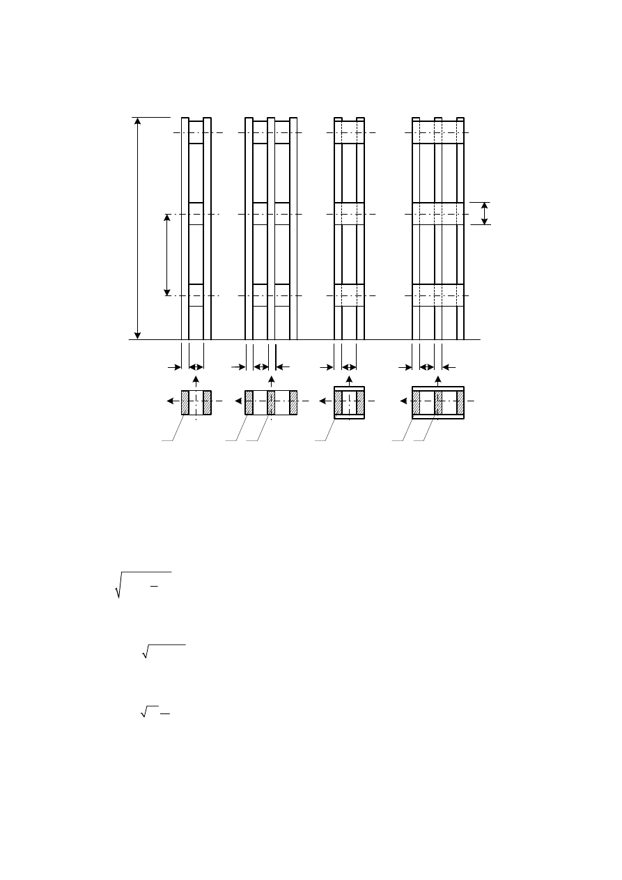
prEN 1995-1-1:2003 (E)
118
A
A
A
A
A
A
z
z
z
z
y
y
y
y
h
h
a
h
a
a
h
h
h
a
l
2
l
1
l
Figure C.1 – Spaced columns
C.3.2
Axial load-carrying capacity
(1) For column deflection in the y-direction (see Figure C.3) the load-carrying capacity should be
taken as the sum of the load-carrying capacities of the individual members.
(2) For column deflection in the z-direction C.1.2 applies with
ef
n
h l
l
l
=
+
2
2
1
2
(C.10)
where:
l is the slenderness ratio for a solid column with the same length, the same area (A
tot
) and
the same second moment of area (I
tot
), i.e.,
tot
tot
A
I
l = l
/
(C.11)
l
1
is the slenderness ratio for the shafts and has to be set into expression (C.10) with a
minimum value of at least 30, i.e.
h
l =
l
1
1
12
(C.12)
n
is the number of shafts;
h is a factor given in Table C.1.
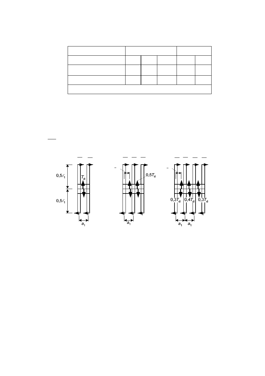
prEN 1995-1-1:2003 (E)
119
Table C.1 – The factor
h
Packs
Gussets
Glued Nailed Bolted
a
Glued Nailed
Permanent/long-term
loading
1 4
3,5 3 6
Medium/short-term loading 1
3
2,5
2
4,5
a
with connectors
C.3.3
Load on fasteners, gussets or packs
(1) The load on the fasteners and the gussets or packs are as shown in Figure C.2 with V
d
according to section C.2.2.
(2) The shear forces on the gussets or packs, see Figure C.2, should be calculated from:
d
d
V l
T
a
=
1
1
(C.13)
d
2
V
2
3
1
a
5
6
1
a
d
2
V
d
3
V
d
4
V
d
3
V
d
3
V
d
4
V
d
4
V
d
4
V
Figure C.2 – Shear force distribution and loads on gussets or packs
C.4
Lattice columns with glued or nailed joints
C.4.1 Assumptions
(1) Lattice columns with N- or V-lattice configurations and with glued or nailed joints are
considered in this section, see Figure C.3.
(2) The following assumptions apply:
- the structure is symmetrical about the y- and z-axes of the cross-section. The lattice on the
two sides may be staggered by a length of
l
1
/2, where
l
1
is the distance between the nodes;
- there are at least three bays;
- in nailed structures there are at least four nails per shear plane in each diagonal at each
nodal point;
- each end is braced;
- the slenderness ratio of the individual flange corresponding to the node length l
1
is not

prEN 1995-1-1:2003 (E)
120
greater than 60;
- no local buckling occurs in the flanges corresponding to the column length l
1
;
- the number of nails in the verticals (of an N-truss) is greater than n sinq, where n is the
number of nails in the diagonals and
q is the inclination of the diagonals.
C.4.2 Load-carrying
capacity
(1) For column deflection in the y-direction (see Figure C.2), the load-carrying capacity should
be taken as the sum of the load-carrying capacities of the individual flanges.
(2) For column deflection in the z-direction C.1.2 applies with
tot
ef
tot
m
l
l
l
ì
+
ï
=
í
ïî
1
max
1,05
(C.14)
where:
l
tot
is the slenderness ratio for a solid column with the same length, the same area and the
same second moment of area, i.e.
tot
h
l
» l
2
(C.15)
m
takes the values given in (3) to (6) below.
(3) For a glued V-truss:
f
f
h
e A
I
m
æ ö
=
ç ÷
è ø
l
2
2
4
(C.16)
where(see Figure C.3):
e
is the eccentricity of the joints;
A
f
is the area of the flange;
I
f
is the second moment of area of the flange;
l is the span;
h
is the distance of the flanges.
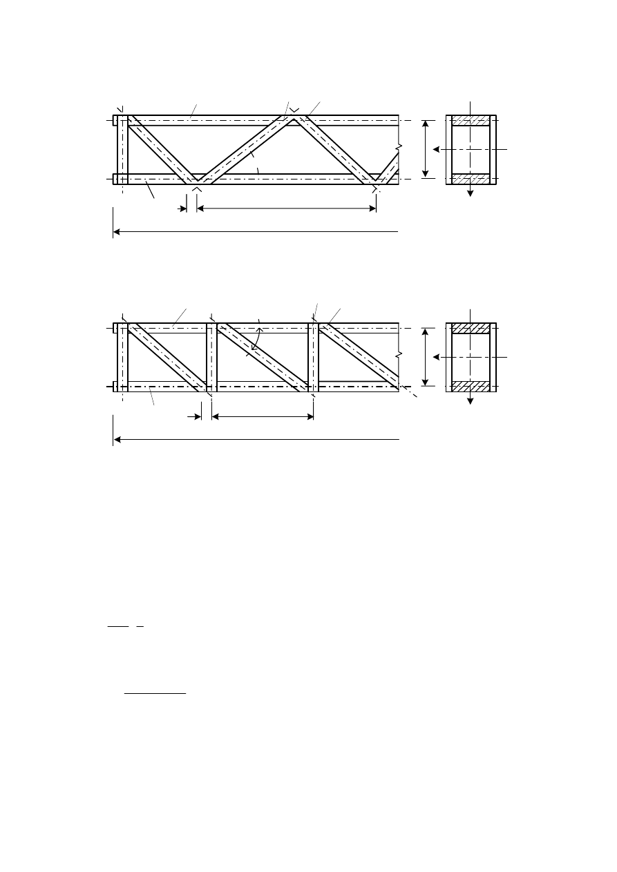
prEN 1995-1-1:2003 (E)
121
h
y
z
A
f
, I
f
(1)
(2)
A
f
, I
f
e
l
1
l
a)
b)
Q
Q
(3)
(4)
A
f
, I
f
A
f
, I
f
e
y
z
h
l
1
l
Key:
(1) number of nails: n
(2) number of nails: n
(3) number of nails:
³n sin q
(4) number of nails: n
Figure C.3 – Lattice columns: (a) V-truss, (b) N-truss
(4) For a glued N-truss:
f
f
A
h
e
I
m
æ ö
=
ç ÷
è ø
l
2
2
(C.17)
(5) For a nailed V-truss:
f
mean
u
h E
A
n K
m
q
=
l
2
25
sin2
(C.18)
where:
n
is the number of nails in a diagonal. If a diagonal consists of two or more pieces, n is the
sum of the nails (not the number of nails per shear plane);
E
mean
is the mean value of modulus of elasticity;

prEN 1995-1-1:2003 (E)
122
K
u
is the slip modulus of one nail in the ultimate limit state.
(6) For a nailed N-truss:
f
mean
u
h E
A
n K
m
q
=
l
2
50
sin2
(C.19)
where:
n
is the number of nails in a diagonal. If a diagonal consists of two or more pieces, n is the
sum of the nails (not the number of nails per shear plane);
K
u
is the slip modulus of one nail for the ultimate limit states.
C.4.3 Shear
forces
(1) C.2.2 applies.

prEN 1995-1-1:2003 (E)
123
Annex D (Informative): Bibliography
EN 338
Structural timber – Strength classes
EN 1194
Glued laminated timber – Strength classes and determination of characteristic
values
Wyszukiwarka
Podobne podstrony:
Eurocode 5 Part 1 2 1995 2004 Design of Timber Structures General Structural Fire Design UK Ann
Eurocode 5 Part 2 1995 2004 Design of timber structures Bridges
Eurocode 2 Design of concrete structures Part 2
Eurocode 2 Design of concrete structures Part 1 3
Eurocode 2 Design of concrete structures Part 2
Eurocode 3 Part 1 12 2007 UK NA Design of Steel Structures Additional Rules for the Extension of
Eurocode 3 Part 1 12 2007 Design of Steel Structures Additional Rules for the Extension of EN 199
Eurocode 6 Part 1 2 1996 2005 Design of Masonry Structures General Rules Structural Fire Design
Eurocode 6 Part 2 1996 2006 Design of Masonry Structures Design Considerations, Selection of Mat
Eurocode 3 Part 1 7 2009 Design of Steel Structures Plated Structures Subject to Out of Plane Loa
Eurocode 3 Part 2 2006 UK NA Design of steel structures Steel bridges
Eurocode 3 Part 1 9 2005 UK NA Design of Steel Structures Fatigue
Eurocode 3 Part 1 4 2006 Design of Steel Structures General rules Supplementary Rules for Stainl
Eurocode 2 Part 3 2006 UK NA Design of concrete structures Liquid retaining and containing struc
Eurocode 3 Part 1 9 2005 Design of Steel Structures Fatigue
Eurocode 3 Part 1 5 2009 Design of Steel Structures Plated Structural Elements
Eurocode 3 Part 3 2 2006 Design of Steel Structures Towers, Masts and Chimneys Chimneys
więcej podobnych podstron