ELECTRICAL SYSTEM
HR45-25, HR45-27, HR45-31, HR45-40S,
HR45-36L, HR45-40LS, HR45-45LSX,
HR45H [B227]
PART NO. 1564268
2200 SRM 1106

SAFETY PRECAUTIONS
MAINTENANCE AND REPAIR
• When lifting parts or assemblies, make sure all slings, chains, or cables are correctly
fastened, and that the load being lifted is balanced. Make sure the crane, cables, and
chains have the capacity to support the weight of the load.
• Do not lift heavy parts by hand, use a lifting mechanism.
• Wear safety glasses.
• DISCONNECT THE BATTERY CONNECTOR before doing any maintenance or repair
on electric lift trucks. Disconnect the battery ground cable on internal combustion lift
trucks.
• Always use correct blocks to prevent the unit from rolling or falling. See HOW TO PUT
THE LIFT TRUCK ON BLOCKS in the Operating Manual or the Periodic Mainte-
nance section.
• Keep the unit clean and the working area clean and orderly.
• Use the correct tools for the job.
• Keep the tools clean and in good condition.
• Always use HYSTER APPROVED parts when making repairs. Replacement parts
must meet or exceed the specifications of the original equipment manufacturer.
• Make sure all nuts, bolts, snap rings, and other fastening devices are removed before
using force to remove parts.
• Always fasten a DO NOT OPERATE tag to the controls of the unit when making repairs,
or if the unit needs repairs.
• Be sure to follow the WARNING and CAUTION notes in the instructions.
• Gasoline, Liquid Petroleum Gas (LPG), Compressed Natural Gas (CNG), and Diesel fuel
are flammable. Be sure to follow the necessary safety precautions when handling these
fuels and when working on these fuel systems.
• Batteries generate flammable gas when they are being charged. Keep fire and sparks
away from the area. Make sure the area is well ventilated.
NOTE:
The following symbols and words indicate safety information in this
manual:
WARNING
Indicates a condition that can cause immediate death or injury!
CAUTION
Indicates a condition that can cause property damage!

Electrical System
Table of Contents
TABLE OF CONTENTS
Description .........................................................................................................................................................
Operation............................................................................................................................................................
General ...........................................................................................................................................................
Location Numbers .....................................................................................................................................
Components ...............................................................................................................................................
Leads/Wires ...............................................................................................................................................
Common Parts ...........................................................................................................................................
Electrical Components ..................................................................................................................................
Part Numbers of Electrical Components ..........................................................................................................
This section is for the following models:
HR45-25, HR45-27, HR45-31, HR45-40S, HR45-36L, HR45-40LS,
HR45-45LSX, HR45H [B227]
©2004 HYSTER COMPANY
i

"THE
QUALITY
KEEPERS"
HYSTER
APPROVED
PARTS

2200 SRM 1106
Operation
Description
This manual provides information on the Operation, Schematics, Wiring, Connectors, and location of the elec-
trical system components.
Operation
GENERAL
The electrical schematic is laid out on several pages.
The index page shows on which page the different
functions can be found. Not all functions will apply
to your truck. See Diagrams 8000 SRM 1084.
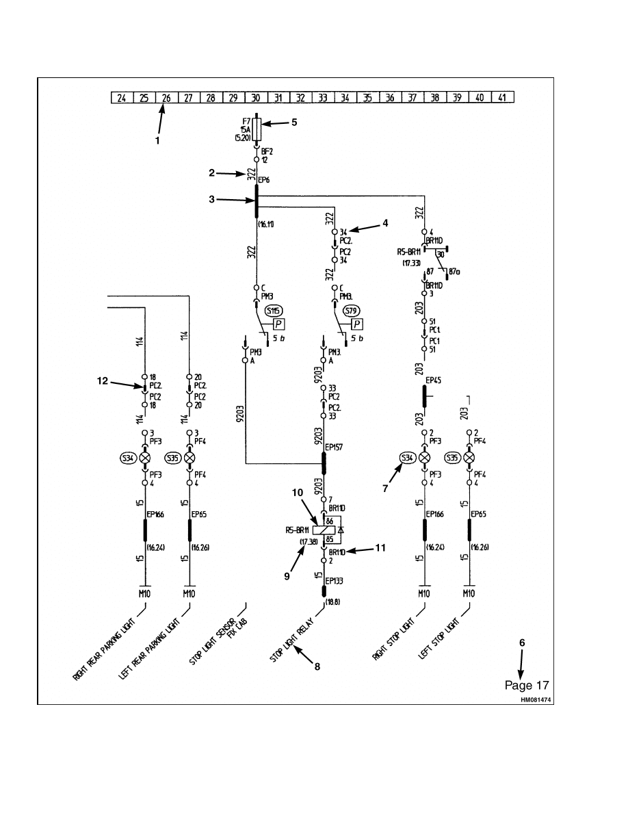
Each page of the electrical schematic is divided into
41 columns. The column numbers are shown in a
horizontal bar at the top of each page. The meaning
of the reference numbers depends on its layout and
its location. See Figure 1.
Location Numbers
All location numbers are placed between brackets.
The number starts with the page number, followed
by the column number. Example: Relay R5-BR11
(17,33) is shown on page 17 in column 33.
The location number shows at which location a re-
lated function or connection exists. When a compo-
nent is shown with several location numbers, then
a function or connection exists at each of the indi-
cated locations. A location number shown at a relay
refers to the contact belonging to that relay. A lo-
cation number shown next to a contact refers to the
relay belonging to that contact. A location number
shown at the end of a line refers to the location where
this line continues.
Components
Components that can be replaced are indicated by
an encircled reference number. See Figure 1, pos.
7. Some of these reference numbers are listed in the
tables in section Part Numbers of Electrical Compo-
nents to identify the spare part number. Normally
the identifiable components are to be selected from
the spare parts manual.
Leads/Wires
Numbers shown just above a line are used to identify
leads/wires. The same numbers are also printed on
the wires themselves. Example: 322 = wire marked
"322."
Wires with the same number are interconnected and
therefore have the same function. Example: Lead/
wire 15 has function "Battery Ground (negative)."
Common Parts
Components starting with a letter followed by a num-
ber concern one of the following common parts:
• B = Square type plug base
• E = Electrovalve, solenoid
• M = Ground
• P = Plug (Round type)
• BR = Relay base, board for the relays
• EP = Splice in harness
• F = Fuse
• R = Relay
1
Operation
2200 SRM 1106
Figure 1. Example Electrical Schematic
2
2200 SRM 1106
Operation
Legend for Figure 1
1.
COLUMN NUMBERS
2.
LEAD/WIRE IDENTIFICATION
3.
CABLE LOOM
4.
PLUG CONNECTION, PIN/CONTACT 34 OF
PLUG PC1
5.
FUSE FUNCTION
6.
PAGE NUMBER, INDEXES THE PAGE NUMBER
FOR THE DIFFERENT FUNCTIONS
7.
REPLACEMENT COMPONENTS (GAUGES,
MOTORS, ALTERNATOR, GENERAL)
8.
FUNCTION INDICATION OF A PARTICULAR
SECTION
9.
(XX,YY) XX IS PAGE NUMBER REFERENCE, YY
IS COLUMN REFERENCE
10. RELAYS
11. RELAY BASE IDENTIFICATION NUMBER
12. CONNECTOR (PLUG) IDENTIFICATION
NUMBER
The numbers at the pin connections for these com-
mon parts refers to the pin number of that common
part. Check the Parts Manual for separate avail-
ability of these common parts.
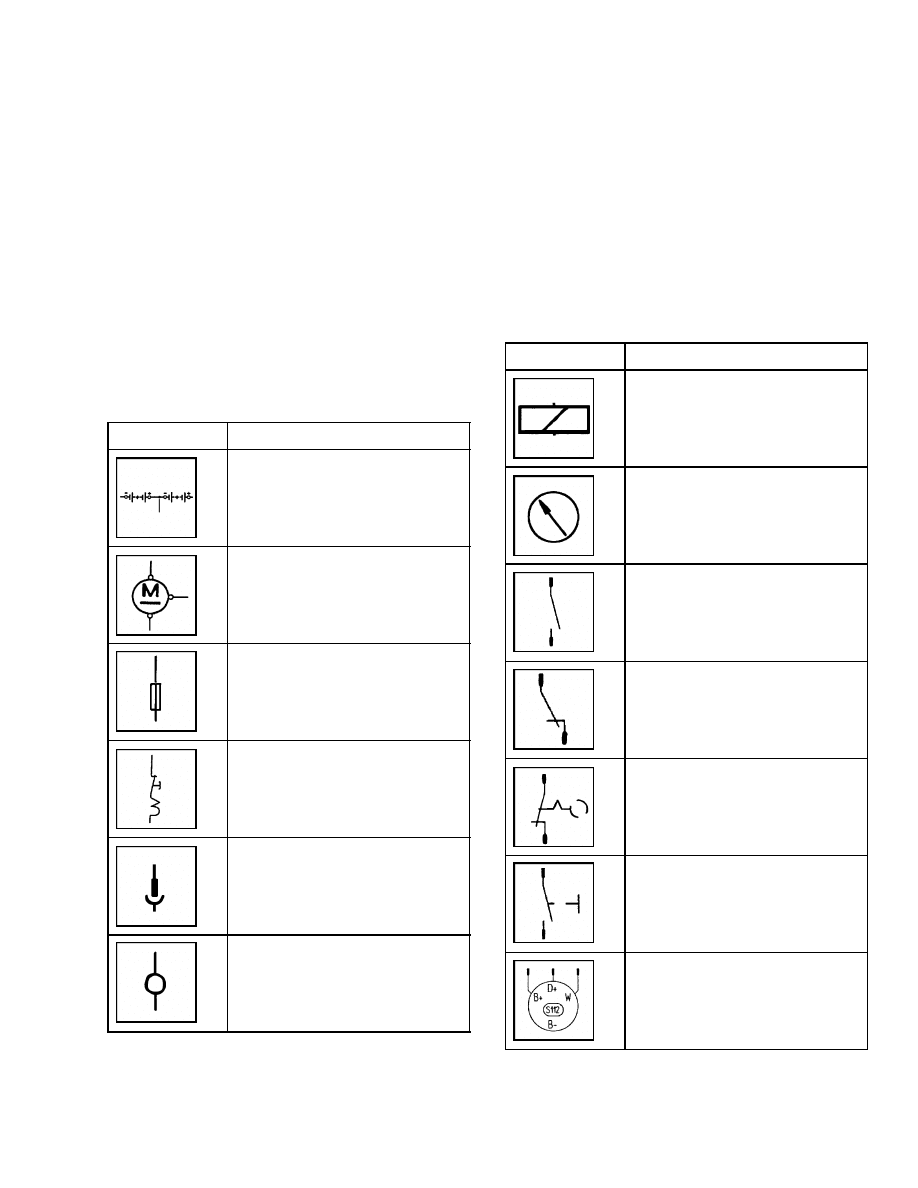
Table 1. Symbols and Components
Symbol
Component
Battery
Starter
Fuse
Circuit breaker with reset
function
Pin connection
Connection
Table 1. Symbols and Components (Continued)
Symbol
Component
Relay
Meter/gauge
Relay contact, normally open
(relay non-energized)
Relay contact, normally closed
(relay non-energized)
Switch
Switch with push button
function
Alternator
3
Operation
2200 SRM 1106
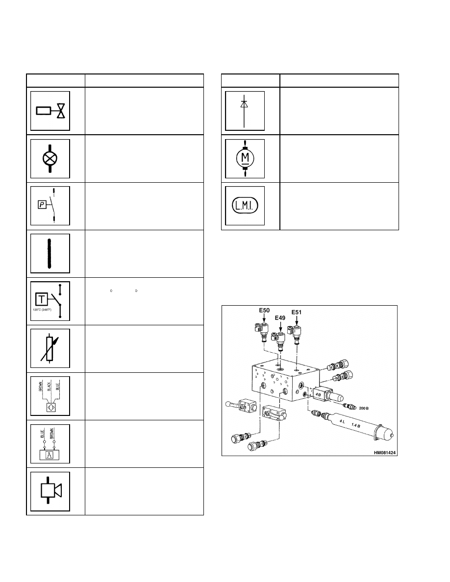
Table 1. Symbols and Components (Continued)
Symbol
Component
Solenoid
Indicator lamp
Pressure switch
Cable loom
Temperature switch, switches on
at 120 C (248 F)
Sensor
Sensor/proximity switch
Sensor
Horn, alarm
Table 1. Symbols and Components (Continued)
Symbol
Component
Diode
DC motor (electrical)
Load limiter
ELECTRICAL COMPONENTS
The following tables give an item number, descrip-
tion, reference, and figure location of the electrical
components. See Figure 2, Figure 3, Table 2, Fig-
ure 4, Table 3, Figure 5, Table 4, Figure 6, and Ta-
ble 5.
Figure 2. Dampening Lock on Boom
4
2200 SRM 1106
Operation
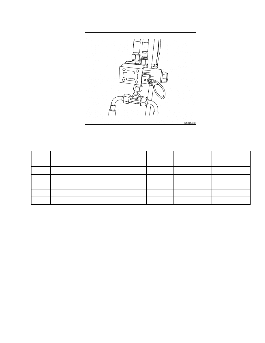
Figure 3. Hydraulic Valve on Boom
Table 2. Solenoids on the Boom
Item
Description
Location
Figure
Part Number
E49
Dampening override
(41.20)
1520299
E50
Right dampening locking
(41.30)
1520299
E51
Left dampening locking
(41.38)
1520299
E54
Spreader leveling
(21.4)
1520299
5
Operation
2200 SRM 1106
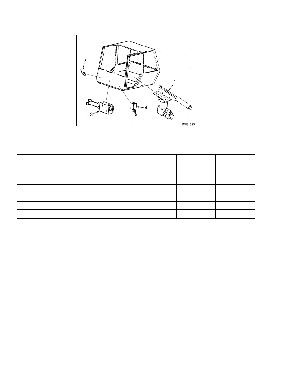
Figure 4. Service and Parking Brake Switches and Sensors
Table 3. Service and Parking Brake Switches and Sensors
Item
Description
Location
Figure
Part Number
S75
Parking brake pressure switch for indicators
(10.28)
Figure 4, Pos. 1
1520169
S77
Parking brake sensor
(13.3)
Figure 4, Pos. 1
1469193
S78
Minimum pressure switch
(8.29)
Figure 4, Pos. 3
1469194
S79
Stoplight sensor
(17.34)
Figure 4, Pos. 3
1469193
S139
Brake sensor
(13.6)
Figure 4, Pos. 4
1551370
6
2200 SRM 1106
Operation
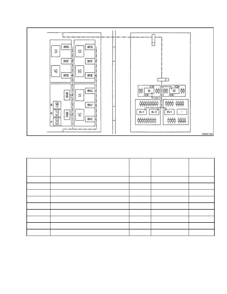
Figure 5. Spreader Relays and Components (Located in the Electrical Box on the PPM Spreader)
Table 4. Spreader Relays and Components in Spreader Electrical Box
Item
Description
Location
Figure
Part
Number
R1 - BR3
Container released on right side. Red light
(39.40)
Figure 5, D1
1469316
R2 - BR3
Container released on left side. Red light
(39.19)
Figure 5, SD
1469316
R1 - BR2
Container seated on right side. White light
(37.31)
Figure 5, P1
1469316
R2 - BR2
Container seated on left side. White light
(37.19)
Figure 5, SP
1469316
R1 - BR4
Container locked on right side. Green light
(39.31)
Figure 5, V1
1469316
R2 - BR4
Container locked on left side. Green light
(39.13)
Figure 5, SV
1469316
R3 - BR5
Spreader leveling disable
41,27
Figure 5, BK1
1469315
R2 - BR5
Spreader telescope speed slow down
36,38
Figure 5, DT50
1469315
R1 - BR5
Flow selection. 40L/20L
33,36
Figure 5, BRSC
1469316
7
Part Numbers of Electrical Components
2200 SRM 1106
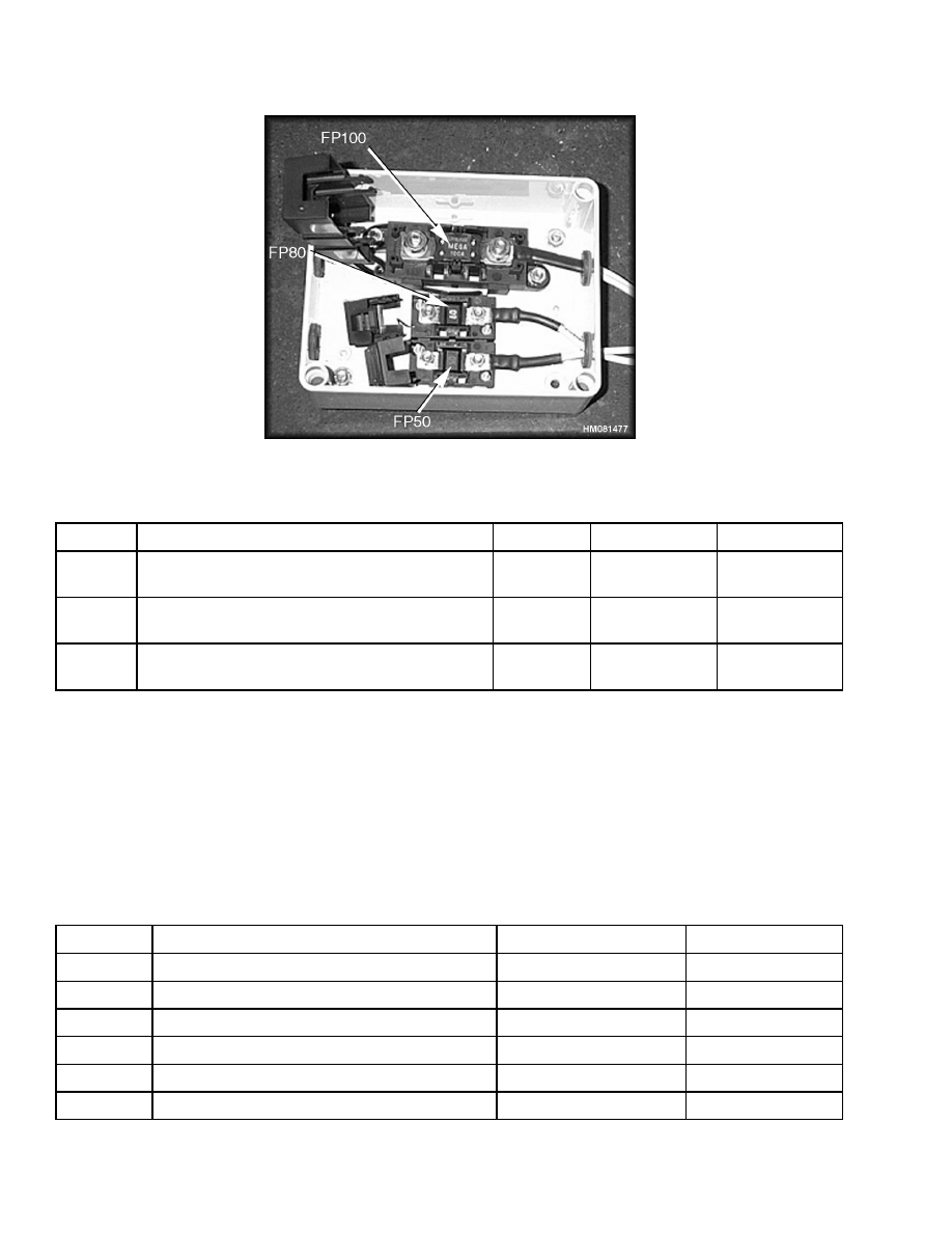
Figure 6. General Fuse Panel (Located in the Battery Box)
Table 5.
Fuses
Item
Description
Location
Figure
Part Number
FP100
100 Amp. Main fuse. Provides protection to all
functions behind the battery shutoff.
(3.26)
1500512
FP80
80 Amp. Main fuse. Provides protection to the
starter motor behind the battery shutoff.
(3.19)
1500514
FP50
50 Amp. Main fuse. Provides general protection
for the direct battery supplies.
(3.28)
1500516
Part Numbers of Electrical Components
Table 6 shows the electrical component reference,
part number, and schematic page number reference.
It provides a link between the electrical components
mentioned on the schematic pages and their part
numbers. The location of some of the components is
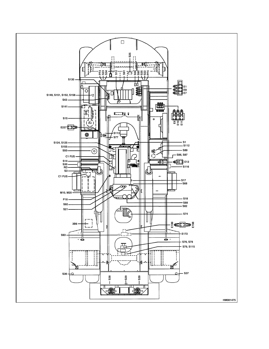
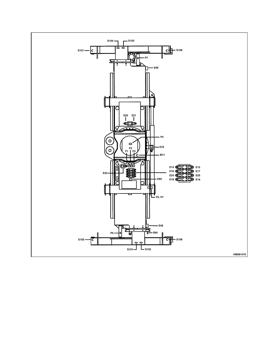
indicated on Figure 7 and Figure 8.
Schematic page numbers refer to page number as
indicated in the right-hand bottom corner in Dia-
grams 8000 SRM 1084. When the schematic page
number has the addition LSX, then it refers to the
LSX version only.
Table 6. Components, Descriptions, and Part Numbers
Item
Description
Part Number
Schematic Page
APC100
APC100 Electronic unit
1476484
11
BAT1,2
Battery
1492663
3
BV1
8 Lights panel
1468883
45
BV2
8 Lights panel
1468906
16
BV3
8 Lights panel
1551428
9
BV4
8 Lights panel
1468890
13
8

2200 SRM 1106
Part Numbers of Electrical Components
Table 6. Components, Descriptions, and Part Numbers (Continued)
Item
Description
Part Number
Schematic Page
B14
4 Relay board
1480679
29 LSX
C1 BR2
2 Relay board
1469318
37
C1 BR3
2 Relay board
1469318
39
C1 BR4
2 Relay board
1469318
39
C1 BR5
5 Relay board
1469314
41
C1 BR10
5 Relay board
1469314
3
C1 BR11
5 Relay board
1469314
18
C1 BR12
2 Relay board
1469318
11
C1 BR13
2 Relay board
1469318
11
C1 BR14
5 Relay board
1469314
35
C1 BR15
5 Relay board
1469314
20
C1 BR16
2 Relay board
1469318
20
C1 BR17
2 Relay board
1469318
22
C1 BR18
5 Relay board
1469314
13
C1-FUS
Fuse board
1551438
4
C12
Diode board
1469321
37
C14
Diode board
1476944
34
C15
Diode board
1469321
36
C16
Diode board
1476945
38
D26
Protection diode
1520261
18
D27
Protection diode
1520261
30
D28
Protection diode
1520261
30
E1
40 liter (11 gal) hydraulic flow
1520299
33
E5
Optional winch up
1520299
32
E6
Optional winch down
1520299
32
E7
Boom derricking up
1520299
21
E8
Overload protection
1520299
30
E9
Joystick flow
1520299
31
E10
Joystick flow
1520299
31
E11
Joystick flow
1520299
31
E12
Optional 3 wraps remaining
1520299
32
E13
Hydraulic oil cooler
1520299
31
E14
Spreader telescope extension
1520299
36
9

Part Numbers of Electrical Components
2200 SRM 1106
Table 6. Components, Descriptions, and Part Numbers (Continued)
Item
Description
Part Number
Schematic Page
E15
Spreader telescope retraction
1520299
36
E16
Spreader sideshift left
1520299
34
E17
Spreader sideshift right
1520299
34
E18
Powered pile slope left
1520299
42
E19
Powered pile slope right
1520299
42
E20
Rotation counterclockwise
1520299
33
E21
Rotation clockwise
1520299
33
E22
Rotation brake release
1520299
33
E23
Spreader telescope speed slow down
1520299
36
E24
Container locking
1520299
38
E25
Container unlocking
1520299
38
E49
Dampening disable when derricking
1520299
41
E50
Dampening lock rearward sway
1520299
41
E51
Dampening lock forward sway
1520299
41
E54
Loaded situation recognition
1520299
21
E60
Spreader oil heating
1520299
44
E172
Outrigger rod side decompression
1520299
14
E187
Sliding cab front position (option)
1520299
20
E188
Optional sliding cab rear position
1520299
20
E198
Outrigger down
1520299
14
E199
Outrigger up
1520299
14
E227
Parking brake
1520299
10
E310
Boom hoist down
1520299
22
FP50
Fuse
1550516
3
FP80
Fuse
1500514
3
FP100
Fuse
1500512
5
F1
Fuse
1520264
5
F2
Fuse
1520262
5
F3
Fuse
1520262
5
F4
Fuse
1520265
5
F5
Fuse
1520262
5
F6
Fuse
1520266
5
F7
Fuse
1520265
5
10

2200 SRM 1106
Part Numbers of Electrical Components
Table 6. Components, Descriptions, and Part Numbers (Continued)
Item
Description
Part Number
Schematic Page
F8
Fuse
1520266
5
F9
Fuse
1520266
5
F10
Fuse
1520262
5
F11
Fuse
1520265
5
F12
Fuse
1520265
5
F13
Fuse
1520265
5
F14
Fuse
1520265
5
F15
Fuse
1520266
5
F16
Fuse
1520265
6
F17
Fuse
1520264
6
F18
Fuse
1520262
6
F19
Fuse
1520264
6
F20
Fuse
1520264
6
F21
Fuse
1520264
6
F22
Fuse
1520264
6
F23
Fuse
1520262
6
F24
Fuse
1520266
6
F25
Fuse
1520265
6
F29
Fuse
1551437
28
F33
Fuse
1520262
6
F34
Fuse
1520265
6
F38
Fuse
1551437
28 LSX
F39
Fuse
1520264
4
F40
Fuse
1520264
4
F41
Fuse
1520264
4
F42
Fuse
1520264
4
F43
Fuse
1520264
4
F44
Fuse
1520264
4
F45
Fuse
1520264
4
F46
Fuse
1520264
4
M1
Spreader ground
23
M10
Battery ground
3
M20
Transmission ground
8
11

Part Numbers of Electrical Components
2200 SRM 1106
Table 6. Components, Descriptions, and Part Numbers (Continued)
Item
Description
Part Number
Schematic Page
PMH
Joystick
1469306
33
P1 – P4
Boom spreader connector
P5 – P7
Boom spreader connector (for moving cab
option)
P17
Engine override connection
1553223
7
RD
Engine starting
1469836
3
R1
Optional fan pressurized cab
1469315
28 LSX
R1-BR2
Container seated
1469316
37
R1-BR3
Twistlock unlocked
1469316
39
R1-BR4
Twistlock locked
1469316
39
R1–BR5
Flow selection 40/20 liter (11/5 gal)
1469316
33
R1 BR10
Battery charge
1469315
3
R1-BR11
Joystick flow selection
1469315
31
R1-BR12
Neutral transmission control
1469316
11
R1-BR13
Transmission override
1469316
11
R1-BR14
Spreader clockwise rotation
1469315
35
R1-BR15
Cab sliding permission
1469315
20
R1-BR16
Sliding cab forward travel cut off
1469316
20
R1-BR17
Boom derricking down permission
1469316
22
R1-BR18
Speed limit
1469315
13
R2
Evaporator
1469315
28 LSX
R2-BR2
Container seated
1469316
37
R2-BR3
Container unlocked
1469316
39
R2-BR4
Container locked
1469316
39
R2-BR5
Spreader telescope speed slow down
1469315
36
R2 BR10
Reverse light relay
1469315
19
R2-BR11
Joystick flow selection
1469315
31
R2-BR12
Outrigger up position
1469316
14
R2-BR13
Transmission override
1469316
11
R2-BR14
Right spreader rotation
1469315
35
R2-BR15
0 to 5 boom angle
1469315
22
R2-BR17
Cab rear position
1469316
21
R2-BR18
Throttle cut-off
1469315
13
R3
Evaporator
1469315
28 LSX
12

2200 SRM 1106
Part Numbers of Electrical Components
Table 6. Components, Descriptions, and Part Numbers (Continued)
Item
Description
Part Number
Schematic Page
R3-BR5
Disable spreader leveling
1469315
41
R3 BR10
Air conditioning compressor
1469315
28
R3-BR11
High beam relay
1469315
18
R3-BR14
Spreader sideshift left
1469315
35
R3-BR15
Stabilizer down
1469315
14
R3-BR18
Container seated
1469315
45
R4
Evaporator
1469315
28 LSX
R4-BR10
Air conditioning motor
1469315
28
R4-BR11
Low beam relay
1469315
18
R4-BR14
Spreader sideshift right
1469315
35
R4-BR15
Stabilizer up
1469315
14
R5-BR10
Horn
1469315
18
R5-BR11
Brake light relay
1469315
17
R5-BR15
Stabilizer up permission
1469315
15
S1
Alternator
1469716
3
S3
Main switch
1469834
3
S4
Mode selection manual/automatic
transmission
1551429
11
S5
Engine shutdown
1487218
10
S6
Radio
1551427
27
S7
Tachometer/hourmeter
1526102
3
S8
Fuel gauge/oil temperature converter
1468923
9
S9
Clutch pressure/hydraulic oil temperature
1468917
9
S10
Spreader telescoping
1520209
36
S11
Container seated override
1551433
37
S12
Pressure sensor boom derricking down
1470526
41
S13
Load moment system override
1551433
30
S14
Starter
1469710
3
S15
Hydraulic oil temperature
1469146
9
S17
Engine speed sensor
1469338
13
S18
Turbine speed sensor
1475358
13
S20
Transmission control
1470377
11
S21
Clutch oil pressure
1469333
9
S22
Left reverse light
1468374
19
13

Part Numbers of Electrical Components
2200 SRM 1106
Table 6. Components, Descriptions, and Part Numbers (Continued)
Item
Description
Part Number
Schematic Page
S23
Right reverse light
1468374
19
S25
Reverse gear audible alarm
1468929
19
S26
Travel forbidden audible alarm
1469226
14
S27
Boom up position sensor
1477407
15
S28
Boom retraction position sensor
1469129
15
S29
Outrigger high position sensor
1469129
14
S30
Optional emergency shutdown
10
S31
Hazard switch
1551434
16
S32
Blinker unit
1472507
16
S33
Blinker audible alarm
1469226
16
S34
Right rear light unit
1468919
16
S35
Left rear light unit
1468918
16
S36
Right front blinker
1468915
16
S37
Left front blinker
1468915
16
S38
Right front headlamp
1468932
18
S39
Left front headlamp
1468932
18
S40
Horn
1488123
18
S41
Cab door closed sensor
1476406
20
S42
Cab door closed sensor
1476406
20
S43
Boom angle sensor 25 and up
1470947
20
S44
Cab working light
1468374
24
S45
Boom working light
1468374
23
S46
Frame working light
1468374
23
S47
Frame working light
1468374
23
S48
Spreader working light
1468374
23
S49
Spreader working light
1468374
23
S50
Fuel gauge
1470614
9
S51
Boom working light
1468374
23
S52
Boom working light
1468374
23
S53
Boom working light
1468374
23
S54
Cab working light
1468374
24
S55
Rotating beacon
1468924
24
S56
Rotating beacon
1468924
24
14

2200 SRM 1106
Part Numbers of Electrical Components
Table 6. Components, Descriptions, and Part Numbers (Continued)
Item
Description
Part Number
Schematic Page
S57
Air conditioning compressor
1488022
29
S58
Roof window wiper
1552946
26
S59
Joystick flow selection sensor
1520303
31
S62
Rotating beacon switch
1520168
24
S63
Roof window wiper
1551368
26
S64
Working light switch
1520167
23
S65
Working light switch
1520167
24
S66
Sliding cab switch
1520167
20
S67
Working light switch
1520167
23
S68
Oil temperature converter
1469146
9
S70
Contact/start key switch
1469263
3
S71
Parking lights switch
1520166
17
S72
Stabilizers
1469259
14
S73
Air conditioning switch
1488029
28
S74
Air filter clogging
1469807
9
S75
Parking brake switch
1520169
10
S76
Front brake oil pressure
1469194
8
S77
Parking brake sensor
1469193
13
S78
Front brake oil pressure
1469194
8
S79
Brake light sensor
1469193
17
S80
Front windshield wiper
1488338
25
S81
Winch hydraulic flow
1471222
32
S82
Boom hoist pressure sensor
1472911
30
S83
Anti-tipping
1469226
30
S84
Anti-tipping sensor
1471902
30
S85
Dampening switch
1520212
41
S86
Hydraulic oil cooler sensor
1470814
31
S87
Hydraulic oil cooler sensor
1470814
31
S88
Transmission oil filter clogging
1469222
9
S89
Brake oil filter clogging
1502348
9
S90
Container seated override alarm
1472511
30
S91
Boom derricking up sensor
1470526
41
S92
Clutch oil pressure
1469329
8
15

Part Numbers of Electrical Components
2200 SRM 1106
Table 6. Components, Descriptions, and Part Numbers (Continued)
Item
Description
Part Number
Schematic Page
S93
Outrigger down position sensor
1477390
14
S94
Spreader telescoping low speed
1469129
36
S95
Joystick flow selection sensor
1520303
31
S96
Powered pile slope switch
1469270
42
S97
Spreader controls
1468360
40
S100
Spreader controls
1468360
40
S101
Twistlock locking sensor
1469129
39
S102
Twistlock unlock sensor
1469129
39
S103
Twistlock locking sensor
1469129
39
S104
Twistlock unlock sensor
1469129
39
S105
Container seated sensor
1469129
37
S106
Container seated sensor
1469129
37
S107
Container seated sensor
1469129
37
S108
Container seated sensor
1469129
37
S109
Switch light/wiper
1521162
16
S110
Test switch
1551436
7
S111
Throttle pedal
1551371
7
S112
Hydraulic oil filter clogging
1502348
9
S113
Parking brake sensor
1469193
10
S114
Fault code switch
1551435
7
S115
Brake light sensor
1469193
17
S116
Optional emergency shutdown
10
S117
Rear windshield wiper
1488329
26
S118
Rear windshield wiper switch
1551368
26
S121
Manual selection 1st Forward/1st Reverse
1551429
11
S122
Container seated override alarm
1472511
30 LSX
S123
Evaporator
1488035
29 LSX
S124
Air conditioning motor
1488053
29
S125
Air conditioning motor
1488053
29
S126
Boom lift interrupt (winch)
1471113
32
S130
Maximum boom angle sensor
1470943
21
S131
3 Wraps remaining
1471190
32
S131
3 Wraps remaining
1471191
32
16

2200 SRM 1106
Part Numbers of Electrical Components
Table 6. Components, Descriptions, and Part Numbers (Continued)
Item
Description
Part Number
Schematic Page
S133
0 to 5 boom angle sensor
1470947
22
S134
Cab rear position sensor
1470943
21
S136
Windshield washer
1488341
25
S139
Brake sensor
1551370
13
S141
Hydraulic oil level
1470615
8
S142
Twistlock lock/unlock switch
1469264
38
S144
Spreader sideshift right
1469311
34
S145
Spreader sideshift left
1469311
34
S146
Counterclockwise spreader rotation
1469311
33
S147
Clockwise spreader rotation
1469311
33
S148
Horn
1469311
33
S149
Defrost thermostat
1488029
28
S150
Winch up override
1551429
32
S151
Air conditioning low pressure sensor
1488049
28
S152
Air conditioning high pressure sensor
1488048
28
S153
Left ceiling light
1488112
26
S154
Right ceiling light
1488115
26
S156
Evaporator
1488035
28,29 LSX
S158
Air conditioning low pressure sensor
1488056
28
S159
Engine control unit
Cummins
7
S165
Right-hand loud speaker
1488113
27
S166
Left-hand loud speaker
1488113
27
S176
Windshield wiper timer
1551439
25
S202
24V/12V converter
1472282
27
17
Part Numbers of Electrical Components
2200 SRM 1106
Figure 7. Electrical Components/Solenoids on the Yardmaster (LSX Shown)
18
2200 SRM 1106
Part Numbers of Electrical Components
Figure 8. Electrical Components/Solenoids on the Spreader
19

NOTES
____________________________________________________________
____________________________________________________________
____________________________________________________________
____________________________________________________________
____________________________________________________________
____________________________________________________________
____________________________________________________________
____________________________________________________________
____________________________________________________________
____________________________________________________________
____________________________________________________________
____________________________________________________________
____________________________________________________________
____________________________________________________________
____________________________________________________________
____________________________________________________________
____________________________________________________________
____________________________________________________________
____________________________________________________________
____________________________________________________________
20


TECHNICAL PUBLICATIONS
2200 SRM 1106
1/04 Printed in United Kingdom
Document Outline
Wyszukiwarka
Podobne podstrony:
897495 2200SRM0514 (01 2004) UK EN
1556871 2200SRM1105 (01 2004) UK EN
1564283 1900SRM1107 (01 2004) UK EN
1538373 2200SRM1065 (02 2004) UK EN
1470232 1900SRM0783 (01 2004) UK EN
897070 2200SRM0288 (01 1994) UK EN
897856 2200SRM0612 (01 1996) UK EN
1559550 2200SRM1097 (10 2004) UK EN
1494143 2200SRM0939 (12 2004) UK EN
1519772 2200SRM1016 (10 2004) UK EN
897415 2200SRM0464 (01 1994) UK EN
910110 2200SRM0143 (08 2004) UK EN
1578950 2200SRM1119 (08 2004) UK EN
1565183 2200SRM1110 (08 2004) UK EN
1595265 2200SRM1204 (01 2005) UK EN
897844 2200SRM0603 (01 1996) UK EN
więcej podobnych podstron