CAPACITIES AND
SPECIFICATIONS
S3.50-5.50XM (S70-120XM) [E004, F004]
PART NO. 1510478
8000 SRM 988

SAFETY PRECAUTIONS
MAINTENANCE AND REPAIR
• When lifting parts or assemblies, make sure all slings, chains, or cables are correctly
fastened, and that the load being lifted is balanced. Make sure the crane, cables, and
chains have the capacity to support the weight of the load.
• Do not lift heavy parts by hand, use a lifting mechanism.
• Wear safety glasses.
• DISCONNECT THE BATTERY CONNECTOR before doing any maintenance or repair
on electric lift trucks. Disconnect the battery ground cable on internal combustion lift
trucks.
• Always use correct blocks to prevent the unit from rolling or falling. See HOW TO PUT
THE LIFT TRUCK ON BLOCKS in the Operating Manual or the Periodic Mainte-
nance section.
• Keep the unit clean and the working area clean and orderly.
• Use the correct tools for the job.
• Keep the tools clean and in good condition.
• Always use HYSTER APPROVED parts when making repairs. Replacement parts
must meet or exceed the specifications of the original equipment manufacturer.
• Make sure all nuts, bolts, snap rings, and other fastening devices are removed before
using force to remove parts.
• Always fasten a DO NOT OPERATE tag to the controls of the unit when making repairs,
or if the unit needs repairs.
• Be sure to follow the WARNING and CAUTION notes in the instructions.
• Gasoline, Liquid Petroleum Gas (LPG), Compressed Natural Gas (CNG), and Diesel fuel
are flammable. Be sure to follow the necessary safety precautions when handling these
fuels and when working on these fuel systems.
• Batteries generate flammable gas when they are being charged. Keep fire and sparks
away from the area. Make sure the area is well ventilated.
NOTE: The following symbols and words indicate safety information in this
manual:
WARNING
Indicates a condition that can cause immediate death or injury!
CAUTION
Indicates a condition that can cause property damage!

Capacities and Specifications
Table of Contents
TABLE OF CONTENTS
Tire Sizes ............................................................................................................................................................
Hydraulic System...............................................................................................................................................
Electrical System ...............................................................................................................................................
Engine Specifications.........................................................................................................................................
Capacities ...........................................................................................................................................................
Lift Truck Weights .............................................................................................................................................
Transmission Pressures (Single-Speed Powershift).........................................................................................
Mast Speeds .......................................................................................................................................................
Torque Specifications .........................................................................................................................................
Frame .............................................................................................................................................................
Engine - GM V-6 ............................................................................................................................................
Engine - Perkins ............................................................................................................................................
Transmission..................................................................................................................................................
Drive Axle ......................................................................................................................................................
Steering System.............................................................................................................................................
Brake System.................................................................................................................................................
Hydraulic System ..........................................................................................................................................
Main Control Valve........................................................................................................................................
Tilt Cylinders .................................................................................................................................................
Lift Cylinders .................................................................................................................................................
Mast................................................................................................................................................................
This section is for the following models:
S3.50-5.50XM (S70-120XM) [E004, F004]
©2005 HYSTER COMPANY
i

"THE
QUALITY
KEEPERS"
HYSTER
APPROVED
PARTS
8000 SRM 988
Electrical System
Tire Sizes
Model
Steering
Drive
S3.50 (S70XM)
18 × 6 × 12.1
22 × 9 × 16
S4.00 (S80XM)
18 × 7 × 12.1
22 × 9 × 16
S4.50-5.50XM (S100-120XM)
18 × 8 × 12.1
22 × 12 × 16
Hydraulic System
Item
Specification
Hydraulic System Capacity
39.3 liter (10.4 gal)
Hydraulic Tank Capacity
(Total Tank Capacity)
35.5 liter (9.4 gal)
Relief Pressures*
Main Control Valve
Lift Circuit
22.0 MPa (3200 psi)
Tilt and Auxiliary Circuit
15.5 MPa (2250 psi)
Steering Circuit
10.7 MPa (1550 psi)
Hydraulic Pump**
Capacity
89 liter/min (23.5 gal/min)
Priority Flow
None
*Oil temperature 50 to 100 C (120 to 210 F) and engine speed at 2500 rpm.
**Oil temperature 80 to 100 C (176 to 210 F) and engine speed at 2550 rpm.
Electrical System
Alternator Output
38 Amps @ 650 rpm (Hot)
GM V-6
62 Amps @ 2200 rpm (Hot)
42 Amps @ 650 rpm (Hot)
Perkins
62 Amps @ 2500 rpm (Hot)
All Models - 12 Volt, Negative Ground
1

Capacities
8000 SRM 988
Engine Specifications
Item
GM V-6 4.3
Perkins 1004-4
Number of Cylinders
6
4
Firing Order
1-6-5-4-3-2
1-3-4-2
Bore
102.00 mm (4.00 in.)
103.00 mm (4.055 in.)
Stroke
88.40 mm (3.50 in.)
127.00 mm (5.00 in.)
Displacement
4.3 liter (262.4 in.
3
)
4.0 liter (244.0 in.
3
)
Compression Ratio
9.3:1
18.5:1
Idle Speed
675 to 725 rpm
725 to 775 rpm
Governor Speed
2400 to 2500 rpm
2450 to 2550 rpm
Stall Speed
Broken in Engine
1810 (Gas) 1735 (LPG)
+300/-50 rpm
2050 rpm ±50 rpm
New Engine
1710 (Gas) 1635 (LPG)
+300/-50 rpm
1950 rpm ±50 rpm
Timing
0 BTDC at 650 rpm
2 BTDC (Static)
Oil Pressure (Minimum)
207 to 380 kPa (30 to 55 psi)
280 kPa (41 psi)
Valve Clearance
Intake
Not adjustable
0.20 mm (0.008 in.) Cold
Exhaust
Not adjustable
0.45 mm (0.018 in.) Cold
Capacities
Item
Quantity
Engine Oil
GM V-6
4.7 liter (5.0 qt)
Perkins 1004-4
8.0 liter (8.5 qt)
Cooling System
18.9 liter (20.0 qt)
Hydraulic Tank (Total Tank Capacity)
35.5 liter (9.4 gal)
Transmission
15.1 liter (16.0 qt)
Differential
5.7 liter (6.0 qt)
Fuel Tank
34.0 liter (9.1 gal)
Brake Fluid
0.2 liter (0.5 pt)
2
8000 SRM 988
Lift Truck Weights
Lift Truck Weights
Unit
kg
lb
S3.50XM (S70XM)
5,515
11,937
S4.00XM (S80XM)
5,780
12,742
S4.00XM BCS (S80XM BCS)
5,995
13,217
S4.50XM (S100XM)
6,768
14,920
S4.50XM BCS (S100XM BCS)
7,245
15,973
S5.50XM (S120XM)
7,433
16,387
S5.50XMS (S120XMS)
7,527
16,589
S5.50XMSPRS (S120XMSPRS)
7,820
17,241
NOTE: Lift trucks equipped with overhead guard, mast, carriage, load backrest, forks, and LPG engine.
NOTE: S3.50-4.00XM (S70-80XM) and S4.00XM BCS (S80XM BCS) have 3099 mm (122 in.) two-stage LFL
mast.
S4.50-5.50XM (S100-120XM), S4.50XM BCS (S100XM BCS), S5.50XMS (S120XMS), and S5.50XMSPRS
(S120XMSPRS) have 2845 mm (112 in.) two-stage LFL mast.
3
Transmission Pressures (Single-Speed Powershift)
8000 SRM 988
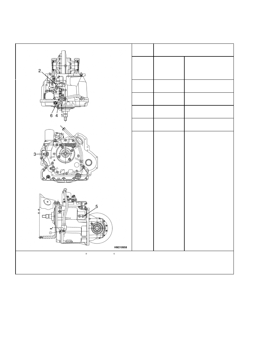
Transmission Pressures (Single-Speed Powershift)
Port
No.
Transmission Pressures*
1
System
Pressure
1170 to 1380** kPa
(170 to 200 psi)
**Relief pressure
1379 kPa (200 psi)
2
Forward
Clutch
895 to 1035 kPa
(130 to 150 psi)
3
Reverse
Clutch
895 to 1035 kPa
(130 to 150 psi)
4
Torque
Converter
655 to 760 kPa
(95 to 110 psi)
5
Lubrication
Pressure
35 to 105 kPa
(5 to 15 psi)
6
Modulator
Pressure
Pressure Variation
*Oil temperature at least 50 to 65 C (120 to 150 F) and engine speed at 2000 rpm.
NOTE: The difference between Forward and Reverse clutch pressure must not be more than:
• Manufacturing limit 48 kPa (7 psi)
• Service limit 70 kPa (10 psi)
4

8000 SRM 988
Mast Speeds
Mast Speeds
Two-Stage Full Free-Lift Mast
Lifting
Lowering
No Load
Rated Load
No Load
Rated Load
Unit
m/sec
ft/min
m/sec
ft/min
m/sec
ft/min
m/sec
ft/min
S3.50-4.00XM
(S70-80XM)
0.60
118
0.56
111
0.36
70
0.50
99
S4.50XM
(S100XM)
0.51
101
0.48
94
0.32
63
0.45
89
S5.50XM
(S120XM)
0.51
101
0.44
87
0.32
63
0.47
92
Two-Stage Limited Free-Lift Mast
Lifting
Lowering
No Load
Rated Load
No Load
Rated Load
Unit
m/sec
ft/min
m/sec
ft/min
m/sec
ft/min
m/sec
ft/min
S3.50-4.00XM
(S70-80XM)
0.68
134
0.62
123
0.47
93
0.55
108
S4.50-5.50XM
(S100-120XM)
0.55
108
0.53
105
0.42
82
0.51
100
Three-Stage Full Free-Lift
Lifting
Lowering
No Load
Rated Load
No Load
Rated Load
Unit
m/sec
ft/min
m/sec
ft/min
m/sec
ft/min
m/sec
ft/min
S3.50-4.00XM
(S70-80XM)
0.63
124
0.58
114
0.44
87
0.53
105
S4.50XM
(S100XM)
0.52
102
0.51
100
0.39
76
0.47
92
S5.50XM
(S120XM)
0.52
102
0.45
89
0.39
76
0.47
92
5

Torque Specifications
8000 SRM 988
Torque Specifications
FRAME
Counterweight Capscrew
1022 N•m (755 lbf ft)
ENGINE - GM V-6
Intake Manifold Capscrews
47 N•m (35 lbf ft)
Valve Cover Capscrews
10 N•m (7 lbf ft)
Exhaust Manifold Capscrews
35 N•m (25 lbf ft)
Center Port 25 N•m (20 lbf ft)
Outer Ports 50 N•m (35 lbf ft)
Camshaft Sprocket Capscrews
25 N•m (20 lbf ft)
Vibration Damper Capscrew
81 N•m (60 lbf ft)
Main Bearing Cap Capscrews
70 N•m (50 lbf ft)
Connecting Rods
45 N•m (35 lbf ft)
Flywheel Capscrews
80 N•m (60 lbf ft)
Flywheel Housing Capscrews
50 N•m (40 lbf ft)
Engine Mount to Engine Capscrews
30 N•m (25 lbf ft)
Engine Mount to Mount Plate Bolts
65 N•m (50 lbf ft)
Engine Mount to Flywheel Housing Capscrews
165 N•m (120 lbf ft)
Engine Mount Bolts
120 N•m (90 lbf ft)
ENGINE - PERKINS
Engine Mount to Engine Capscrews
65 N•m (50 lbf ft)
Engine Mount Bolts
120 N•m (90 lbf ft)
TRANSMISSION
Transmission Cover Capscrews
40 N•m (30 lbf ft)
Oil Pump Capscrews
40 N•m (30 lbf ft)
Torque Converter Housing Capscrews
40 N•m (30 lbf ft)
Control Valve Capscrews
20 N•m (15 lbf ft)
Differential Case Capscrews
140 N•m (105 lbf ft)
Ring Gear Capscrews
140 N•m (105 lbf ft)
Output Gear Nut
750 N•m (550 lbf ft)
Torque Converter Drive Plate Capscrews
45 N•m (35 lbf ft)
Differential Bearing Caps
225 N•m (166 lbf ft)
DRIVE AXLE
Brake Assembly to Axle Nuts
340 to 375 N•m (251 to 277 lbf ft)
Axle Mount to Frame
320 to 350 N•m (235 to 258 lbf ft)
Axle Shaft Flange Capscrews
225 to 250 N•m (166 to 184 lbf ft)
Axle Housing to Transmission Capscrews
65 N•m (48 lbf ft)
Hub Adjustment Nut
205 N•m (151 lbf ft) Initial
35 N•m (26 lbf ft) Final
Wheel Nuts
610 to 680 N•m (450 to 502 lbf ft)
STEERING SYSTEM
Axle Mount Capscrews
90 N•m (66 lbf ft)
6

8000 SRM 988
Torque Specifications
Bearing Cap for Spindle
45 N•m (35 lbf ft)
Tie Rod Castle Nut
175 N•m (129 lbf ft)
Steering Cylinder Capscrews
225 N•m (166 lbf ft)
Wheel Bearing Adjustment Nut
200 N•m (148 lbf ft) Initial
35 N•m (26 lbf ft) Final
BRAKE SYSTEM
Back Plate Capscrews
340 N•m (251 lbf ft)
HYDRAULIC SYSTEM
Capscrews for Special Blocks for
Pump Drive Chain
20 N•m (15 lbf ft)
MAIN CONTROL VALVE
Through Bolt Nuts (5/16 in.)
20 N•m (15 lbf ft)
Through Bolts Nuts (3/8 in.)
45 N•m (35 lbf ft)
TILT CYLINDERS
Piston Nut
400 to 440 N•m (295 to 325 lbf ft)
Retainer
400 to 500 N•m (295 to 370 lbf ft)
Rod End Lock Capscrews
90 N•m (66 lbf ft)
Anchor Pin Retainer Capscrews
77 N•m (57 lbf ft)
LIFT CYLINDERS
Main Lift Cylinder Retainer Cap
340 to 410 N•m (251 to 302 lbf ft)
Free-Lift Cylinder Retainer Cap
400 to 475 N•m (295 to 350 lbf ft)
Free-Lift Cylinder Mount Capscrews
121 N•m (89 lbf ft)
MAST
Pivot Pin Capscrews
320 N•m (236 lbf ft)
Sideshift Carriage
Lower Hook Capscrews 78 N•m (58 lbf ft)
Side Roller Mount Capscrews 90 N•m (66 lbf ft)
7

NOTES
____________________________________________________________
____________________________________________________________
____________________________________________________________
____________________________________________________________
____________________________________________________________
____________________________________________________________
____________________________________________________________
____________________________________________________________
____________________________________________________________
____________________________________________________________
____________________________________________________________
____________________________________________________________
____________________________________________________________
____________________________________________________________
____________________________________________________________
____________________________________________________________
____________________________________________________________
____________________________________________________________
____________________________________________________________
____________________________________________________________
8


TECHNICAL PUBLICATIONS
8000 SRM 988
6/05 (5/04)(9/03)(11/01) Printed in United Kingdom
Document Outline
- toc
Wyszukiwarka
Podobne podstrony:
1554635 8000SRM1079 (06 2004) UK EN
1466217 1900SRM0743 (06 2005) UK EN
897875 8000SRM0616 (03 2005) UK EN
1580518 2200SRM1130 (06 2005) UK EN
1580526 8000SRM1151 (05 2005) UK EN
1596605 8000SRM1203 (07 2005) UK EN
1495208 8000SRM0949 (03 2005) UK EN
1458783 8000SRM0592 (03 2005) UK EN
1596604 8000SRM1202 (08 2005) UK EN(1)
1482638 8000SRM0805 (09 2005) UK EN
1534740 8000SRM1061 (01 2005) UK EN
1598591 8000SRM1208 (05 2005) UK EN
1554635 8000SRM1079 (06 2004) UK EN
więcej podobnych podstron