MAST
DESCRIPTION
H/S/E1.50-1.75XM (H/S/E25-35XM) [C010, D001, D010, D114, E001];
H/S/E2.00XMS (H/S/E40XMS) [C010, D001, D010, D114, E001];
H/S/E/2.00-3.20XM (H/S/E/40-65XM) [D177, D187, F108];
J2.00-3.20XM (J40-60XM, J40-60XM
2
) [A216];
J2.00-3.20XM (J40-65Z) [A416];
S/E/J2.00-3.00XL With Mast S/N C507-509 and C562-564
(S/E/J40-60XL) [A187, B168, B187, C108, C187];
J1.60-2.00XMT (J30-40XMT) [C160, F160];
H2.00-3.20XM (H45-65XM) [H177];
J30-40XMT
2
[H160];
E1.50-2.00XM (E25-35Z, E40ZS) [E114];
E2.00-3.20XM (E45-65Z) [G108];
J1.60-2.00XMT (J30-40ZT) [J160]
PART NO. 897506
4000 SRM 521

SAFETY PRECAUTIONS
MAINTENANCE AND REPAIR
• When lifting parts or assemblies, make sure all slings, chains, or cables are correctly
fastened, and that the load being lifted is balanced. Make sure the crane, cables, and
chains have the capacity to support the weight of the load.
• Do not lift heavy parts by hand, use a lifting mechanism.
• Wear safety glasses.
• DISCONNECT THE BATTERY CONNECTOR before doing any maintenance or repair
on electric lift trucks. Disconnect the battery ground cable on internal combustion lift
trucks.
• Always use correct blocks to prevent the unit from rolling or falling. See HOW TO PUT
THE LIFT TRUCK ON BLOCKS in the Operating Manual or the Periodic Mainte-
nance section.
• Keep the unit clean and the working area clean and orderly.
• Use the correct tools for the job.
• Keep the tools clean and in good condition.
• Always use HYSTER APPROVED parts when making repairs. Replacement parts
must meet or exceed the specifications of the original equipment manufacturer.
• Make sure all nuts, bolts, snap rings, and other fastening devices are removed before
using force to remove parts.
• Always fasten a DO NOT OPERATE tag to the controls of the unit when making repairs,
or if the unit needs repairs.
• Be sure to follow the WARNING and CAUTION notes in the instructions.
• Gasoline, Liquid Petroleum Gas (LPG), Compressed Natural Gas (CNG), and Diesel fuel
are flammable. Be sure to follow the necessary safety precautions when handling these
fuels and when working on these fuel systems.
• Batteries generate flammable gas when they are being charged. Keep fire and sparks
away from the area. Make sure the area is well ventilated.
NOTE:
The following symbols and words indicate safety information in this
manual:
WARNING
Indicates a condition that can cause immediate death or injury!
CAUTION
Indicates a condition that can cause property damage!

Mast
Table of Contents
TABLE OF CONTENTS
General ...............................................................................................................................................................
Description and Operation ................................................................................................................................
Carriages ........................................................................................................................................................
Mast Mounts ..................................................................................................................................................
Two-Stage Mast, Limited Free-Lift (LFL) ........................................................................................................
Description and Operation ............................................................................................................................
Two-Stage Mast, Full Free-Lift (FFL) ..............................................................................................................
Description and Operation ............................................................................................................................
Three-Stage Mast, Full Free-Lift (FFL) ...........................................................................................................
Description and Operation ............................................................................................................................
Cylinder Cushion During Lifting Sequence .....................................................................................................
Cylinder Cushion During Lowering Sequence .................................................................................................
This section is for the following models:
H/S/E1.50-1.75XM (H/S/E25-35XM) [C010, D001, D010, D114, E001];
H/S/E2.00XMS (H/S/E40XMS) [C010, D001, D010, D114, E001];
H/S/E/2.00-3.20XM (H/S/E/40-65XM) [D177, D187, F108];
J2.00-3.20XM (J40-60XM, J40-60XM
2
) [A216];
J2.00-3.20XM (J40-65Z) [A416];
S/E/J2.00-3.00XL With Mast S/N C507-509 and C562-564 (S/E/J40-60XL)
[A187, B168, B187, C108, C187];
J1.60-2.00XMT (J30-40XMT) [C160, F160];
H2.00-3.20XM (H45-65XM) [H177];
J30-40XMT
2
[H160];
E1.50-2.00XM (E25-35Z, E40ZS) [E114];
E2.00-3.20XM (E45-65Z) [G108];
J1.60-2.00XMT (J30-40ZT) [J160]
©2004 HYSTER COMPANY
i

"THE
QUALITY
KEEPERS"
HYSTER
APPROVED
PARTS
4000 SRM 521
Description and Operation
General
This section has the description and operation of the
masts. Repair procedures for the masts are described
in the section Mast, Repairs 4000 SRM 522. The
description and repairs for the tilt cylinders are de-
scribed in the section Tilt Cylinders 2100 SRM 103.
The mast is used to lift a load vertically. The mast
has two movements controlled by hydraulic cylin-
ders: forward and backward tilt, and the lifting and
lowering of the mast weldments and carriage. The
outer weldment can move on the pivot pins at the
mast mounts.
The operation of the tilt cylinders
causes the mast to tilt forward and backward. The
tilt cylinders are fastened between the frame of the
lift truck and the outer mast weldment. Hydraulic
lift cylinders are installed vertically on the masts.
The lift cylinders raise and lower the mast weld-
ments and the carriage.
There are three types of masts available:
• Two-stage, Limited Free-Lift
• Two-stage, Full Free-Lift
• Three-stage, Full Free-Lift
Each type of mast is described separately in this sec-
tion.
Description and Operation
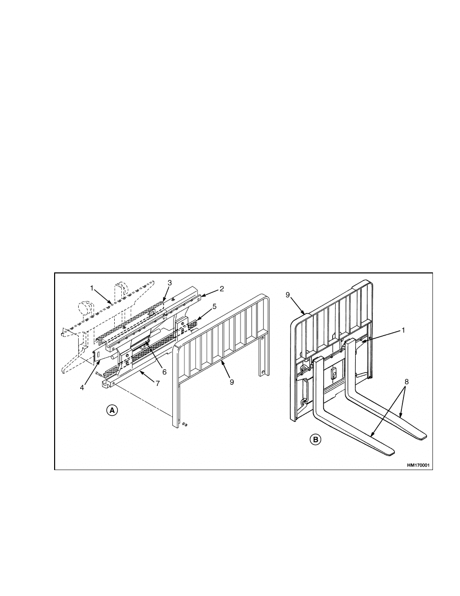
CARRIAGES
The carriage is a part of the mast assembly. Load
rollers that are attached to the carriage travel in the
inner channels of the inner mast weldment. Forks or
other types of load handling equipment are attached
to the carriage. A load backrest extension is attached
to the carriage and adds support for a load that has
multiple pieces. See Figure 1.
A. HANG-ON SIDESHIFT CARRIAGE
B. STANDARD CARRIAGE WITH FORKS
1.
STANDARD CARRIAGE
2.
TOP BAR
3.
TOP BEARING
4.
CYLINDER MOUNTING BRACKET
5.
BOTTOM BEARING
6.
SIDESHIFT CYLINDER
7.
BOTTOM BAR
8.
FORKS
9.
LOAD BACKREST EXTENSION
Figure 1. Carriages
1
Description and Operation
4000 SRM 521
The hang-on sideshift carriage lets the operator
move the forks and load from side to side.
This
function makes it easier for the operator to align the
forks with a load or align the load with a stack. The
hang-on sideshift carriage hangs on the fork bars of
the standard carriage. Special bushings fit between
the hang-on sideshift carriage and the fork bars. A
sideshift cylinder is installed on a plate that fits on
the standard carriage. The sideshift cylinder moves
the hang-on sideshift carriage on the standard car-
riage.
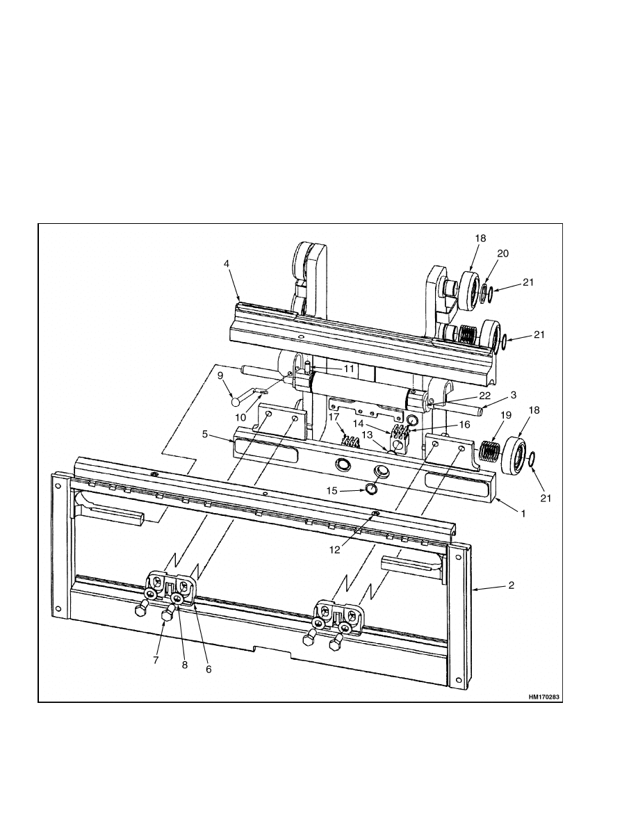
The integral sideshift carriage lets the operator move
the forks and load from side to side. This function
makes it easier for the operator to align the forks
with a load or align the load with a stack. The in-
tegral sideshift carriage is a complete carriage and
sideshift assembly. The sideshift cylinder moves the
sideshift carriage on the standard carriage. See Fig-
ure 2.
Figure 2. Integral Sideshift Carriage
2
4000 SRM 521
Description and Operation
Legend for Figure 2
1.
INNER CARRIAGE
2.
OUTER CARRIAGE
3.
SIDESHIFT CYLINDER
4.
UPPER BEARING
5.
LOWER BEARING
6.
LOWER HOOK
7.
CAPSCREW
8.
WASHER
9.
CLEVIS PIN
10. HAIRPIN
11. PIN
12. LUBE FITTING
13. PIN
14. CHAIN ANCHOR
15. SNAP RING
16. PIN
17. COTTER PIN
18. LOAD ROLLER
19. SHIMS
20. SPACER
21. SNAP RING
22. SPACER
MAST MOUNTS
The mast can tilt forward and backward. Tilt cylin-
ders are fastened between the frame of the lift truck
and the outer mast weldment to change the angle of
the mast and forks.
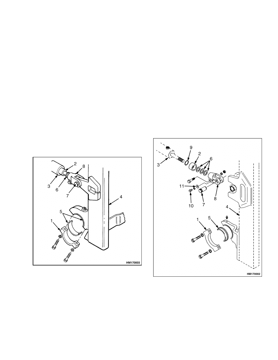
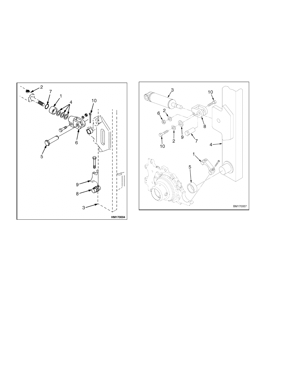
On the S/E/J2.00-3.00XL (S/E/J40-60XL), the mast
pivots directly on the drive axle housing. The mounts
are part of a casting that includes the lower cross-
member for the outer channel. Each mount has a re-
tainer cap that attaches the mast to the axle housing.
Each mast mount uses two bushings. See Figure 3.
1.
RETAINER CAP
2.
SPACER
3.
TILT CYLINDER
4.
OUTER MAST
WELDMENT
5.
BUSHING
6.
SHIMS
7.
PIN
8.
ROD END
Figure 3. Mast Mounts
On
H1.50-1.75XM,
H2.00XMS
(H/S25-35XM,
H/S40XMS), E1.50-1.75XM, E2.00XMS (E25-35XM,
E40XMS) (D114), E1.50-2.00XM (E25-35Z, E40ZS)
(E114), and J1.60-2.00XMT (J30-45XMT) trucks, the
mast pivots directly on the drive axle housing. The
mounts are part of a casting that includes the lower
crossmember for the outer channel.
Each mount
has a retainer cap that attaches the mast to the
axle housing. Each mast mount uses one bushing.
There are no bushings used in the retainer caps. See
Figure 4.
1.
RETAINER CAP
2.
SPACER
3.
TILT CYLINDER
4.
OUTER MAST
WELDMENT
5.
BUSHING
6.
SHIMS
7.
PIN
8.
ROD END
9.
O-RING
10. CAPSCREW
11. FLAT WASHER
Figure 4. Mast Mounts
3
Description and Operation
4000 SRM 521
On the H/S/2.00-3.20XM (H/S/40-65XM), E2.00-
3.20XM (E40-65XM) (F108), E2.00-3.20XM (E45-
65Z) (G108), J2.00-3.20XM (J40-60XM, J40-60XM
2
)
(A216), and J2.00-3.20XM (J40-65Z) (A416) trucks,
pivot pins are installed in the drive axle hangers.
The outer mast weldment has mounts that fit on
the pivot pins. Capscrews hold the mast to the pivot
pins. See Figure 5.
1.
SPACER
2.
TILT CYLINDER
3.
OUTER MAST
WELDMENT
4.
SHIMS
5.
PIN
6.
ROD END
7.
O-RING
8.
PIVOT PIN
9.
DRIVE AXLE
HANGER (MAST
MOUNT)
10. COTTER PIN
Figure 5. Mast Mounts
On J30-40ZT trucks, the mast pivots on two stub-
shafts welded to the sides of the outer mast weld-
ment. The mast mounts are part of the transmission
housing, which bolt to the truck frame. Each mount
uses one bushing. Each mount has a retainer cap
that attaches the mast to the mast mount. Each re-
tainer is held in place with four capscrews. See Fig-
ure 6.
1.
RETAINER CAP
2.
LOCKWASHER
3.
TILT CYLINDER
4.
OUTER MAST
WELDMENT
5.
BUSHING
6.
NUT
7.
PIN
8.
ROD END
9.
WASHER
10. CAPSCREW
Figure 6. Mast Mounts
4
4000 SRM 521
Two-Stage Mast, Limited Free-Lift (LFL)
Two-Stage Mast, Limited Free-Lift (LFL)
DESCRIPTION AND OPERATION
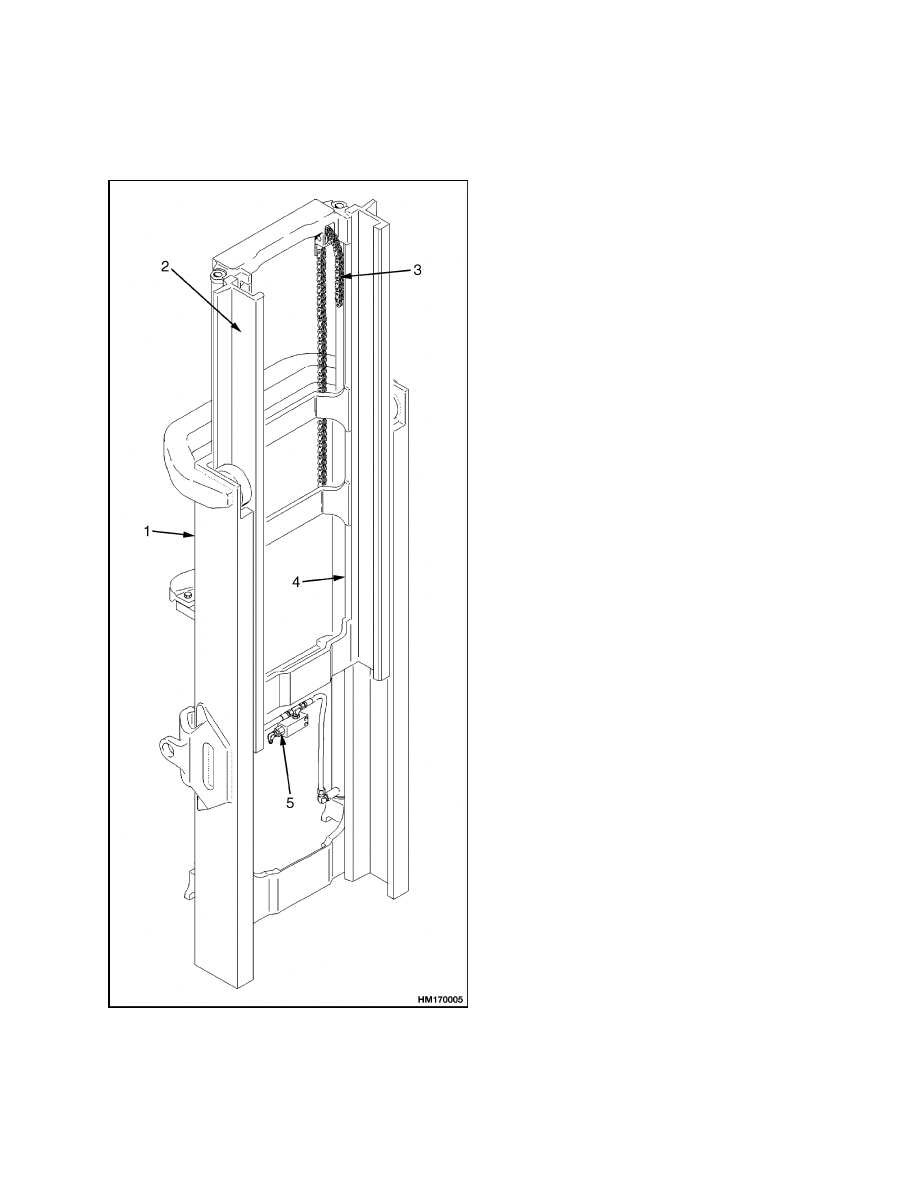
Figure 7. Two-Stage Mast, Limited Free-Lift
(LFL)
Legend for Figure 7
NOTE: TYPICAL MAST ASSEMBLY IS SHOWN
HERE.
1.
OUTER
WELDMENT
2.
INNER WELDMENT
3.
LIFT CHAIN(S)
4.
LIFT CYLINDER(S)
5.
LOWERING
CONTROL VALVE
(EXTERNAL)
The two-stage mast with limited free-lift has an outer
weldment, an inner weldment, and two lift cylinders.
See Figure 7. At the base of the inner weldment there
is one load roller on each side. These load rollers
travel along the flanges inside the outer weldment.
At the top of the outer weldment there is also one load
roller on each side. These load rollers travel along
the flanges on the outside of the inner weldment. The
angle of the load rollers permits them to control the
forces from the front, back, and sides of the mast.
The strip bearings are installed at the top of each
outer channel. The strip bearings can be adjusted
by shims to help keep the correct clearance between
the outer weldment and the inner weldment.
The two single-stage lift cylinders are installed at the
back of the outer weldment. The base of each lift
cylinder sits in a mount at the bottom crossmember
on the outer weldment. The top of each lift cylinder
(cylinder rods) fits into a guide at the top of the in-
ner weldment. Operation of the lift cylinders extends
and retracts the inner weldment. See Figure 8.
Two lift chains move the carriage. The chains fasten
to mounts that are near the top of the lift cylinder
shells. The chains go up and over the chain sheaves
and connect to the carriage. The chain sheaves are
installed at the top crossmember of the inner weld-
ment. When the lift cylinders extend, the lift chains
transfer the force from the lift cylinders to the car-
riage. The inner weldment and carriage can raise a
small amount before the overall height of the mast
increases. During lifting, the inner weldment moves
at the same speed as the lift cylinders. The carriage
moves at twice the speed of the inner weldment.
When the lift cylinders retract, the weight of the load,
carriage, and inner weldment pushes the oil from the
lift cylinders. The oil flows from the lowering control
valves in the lift cylinders, through the external low-
ering control valve to the hydraulic tank.
5
Two-Stage Mast, Full Free-Lift (FFL)
4000 SRM 521
Each cylinder has a check valve in the bottom of the
rod assembly. When the cylinder is fully extended, oil
above the piston is forced through the check valve.
This action allows the cylinder to fully extend. See
Cylinder Cushion During Lowering Sequence.
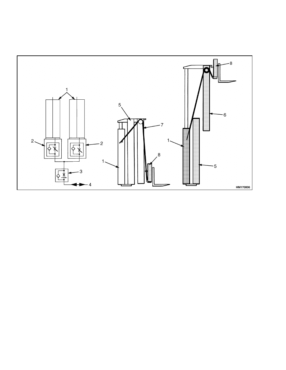
1.
LIFT CYLINDER
2.
LOWERING CONTROL VALVE (INTERNAL)
3.
LOWERING CONTROL VALVE (EXTERNAL)
4.
TO/FROM MAIN CONTROL VALVE
5.
OUTER WELDMENT
6.
INNER WELDMENT
7.
LIFT CHAIN
8.
CARRIAGE
Figure 8. Operation of Two-Stage Mast, Limited Free-Lift (LFL)
Two-Stage Mast, Full Free-Lift (FFL)
DESCRIPTION AND OPERATION
The two-stage, full free-lift mast has an inner weld-
ment and an outer weldment. See Figure 9. It is
called a full free-lift mast because the carriage can
travel to the top of the inner weldment without ex-
tending the inner weldment. The full free-lift mast
has the same load roller and strip bearing arrange-
ments as the two-stage, limited free-lift mast.
The two main lift cylinders are installed at the back
of the outer weldment. The base of each lift cylinder
sits in a mount at the bottom crossmember on the
outer weldment. The top of each lift cylinder (cylin-
der rod) fits into a guide at the top of the inner weld-
ment. The free-lift cylinder is installed in the inner
weldment. Each of the lift cylinders has an inter-
nal lowering control valve. A single external lower-
ing control valve is connected by tubing to all the lift
cylinders.
The free-lift chains connect at one end to the cross-
member for the free-lift cylinder. Two chain sheaves
are installed on a crosshead on the cylinder rod of the
free-lift cylinder. The chains go over sheaves on the
crosshead and connect to the carriage.
6
4000 SRM 521
Two-Stage Mast, Full Free-Lift (FFL)
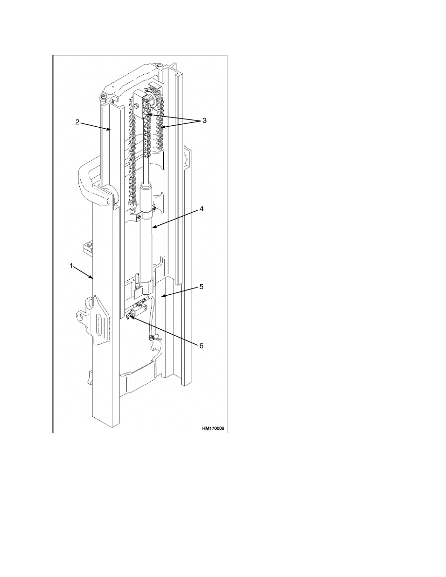
Figure 9. Two-Stage Full Free-Lift Mast
Legend for Figure 9
NOTE: TYPICAL MAST ASSEMBLY IS SHOWN
HERE.
1.
OUTER WELDMENT
2.
INNER WELDMENT
3.
FREE-LIFT CHAIN
4.
FREE-LIFT CYLINDER
5.
MAIN LIFT CYLINDER(S)
6.
LOWERING CONTROL VALVE (EXTERNAL)
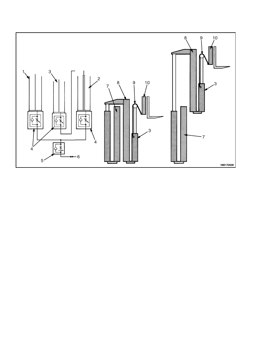
The three lift cylinders are connected by hoses and
tubing as shown in Figure 10. When the mast is ex-
tended, oil flows from the main control valve to the
base of the main lift cylinders. The oil flows through
the left-hand cylinder rod and through tubing to the
base of the free-lift cylinder. The free-lift cylinder
raises only the carriage. When the free-lift cylinder
is fully extended, the two main lift cylinders extend
the inner weldment. The free-lift cylinder extends
first because it has less weight to lift. When the load
is lowered, the main lift cylinders lower first because
they have a greater load. The oil flows from the main
lift cylinders, through the lowering control valve to
the hydraulic tank. Oil from the free-lift cylinder
flows from the cylinder through tubing to the cylin-
der rod on the left side of the mast. The oil flows from
the left-hand lift cylinder to the hydraulic tank.
The free-lift cylinder must have 0.5 liter (0.5 qt) of oil
above the piston. This oil provides a hydraulic cush-
ion when the cylinder reaches the top of its stroke. A
check valve and orifice system in the bottom of the
rod assembly keeps the oil at the correct level. When
the cylinder is fully extended, excess oil above the
piston is forced through the check valve. This action
allows the cylinder to fully extend.
The right hand main lift cylinder has an orifice sys-
tem in the bottom of the rod assembly. This sys-
tem provides a hydraulic cushion when the cylinder
reaches the bottom of its stroke. See Cylinder Cush-
ion During Lifting Sequence.
7
Three-Stage Mast, Full Free-Lift (FFL)
4000 SRM 521
1.
RIGHT-HAND LIFT CYLINDER
2.
LEFT-HAND LIFT CYLINDER
3.
FREE-LIFT CYLINDER
4.
LOWERING CONTROL VALVE (INTERNAL)
5.
LOWERING CONTROL VALVE (EXTERNAL)
6.
TO/FROM MAIN CONTROL VALVE
7.
OUTER WELDMENT
8.
INNER WELDMENT
9.
LIFT CHAIN
10. CARRIAGE
Figure 10. Operation of Two-Stage Mast, Full Free-Lift (FFL)
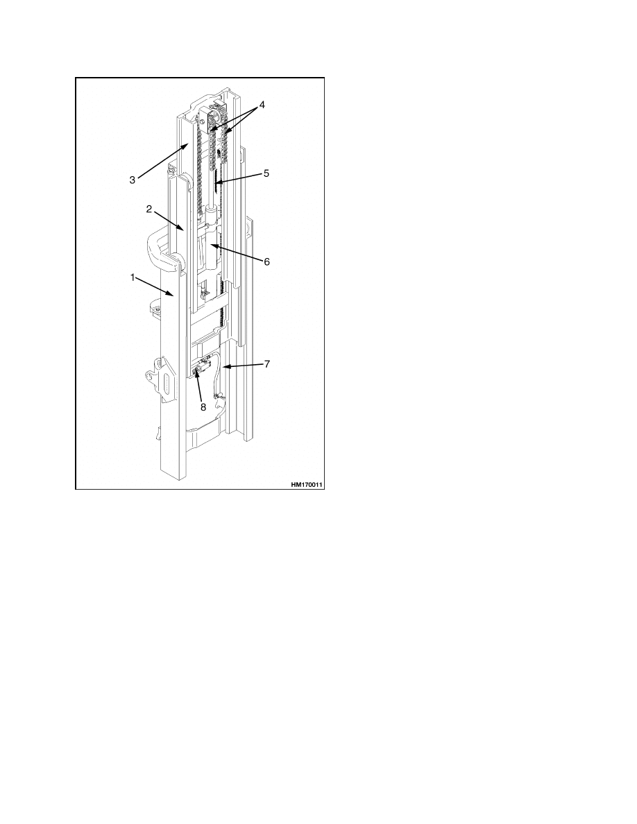
Three-Stage Mast, Full Free-Lift (FFL)
DESCRIPTION AND OPERATION
The three-stage mast has three weldments: outer,
intermediate, and inner. See Figure 11. Two sin-
gle-stage main lift cylinders and a free-lift cylinder
are used to raise the carriage and extend the mast.
It is called a full free-lift mast because the carriage
can travel to the top of the inner weldment without
extending the inner weldment. The weldments are
telescopic and have the load roller and strip bearing
arrangements similar to the two-stage mast. The two
main lift cylinders are installed at the back of the
outer weldment. The base of each lift cylinder sits
in a mount at the bottom crossmember of the outer
weldment. The top of each main lift cylinder (cylin-
der rod) fits into a guide at the top crossmember of
the intermediate weldment. The free-lift cylinder is
installed to the inner weldment. Each lift cylinder
has an internal lowering control valve. A single ex-
ternal lowering control valve is connected by tubing
to all of the lift cylinders.
8
4000 SRM 521
Three-Stage Mast, Full Free-Lift (FFL)
NOTE: TYPICAL MAST ASSEMBLY IS SHOWN
HERE.
1.
OUTER WELDMENT
2.
INTERMEDIATE WELDMENT
3.
INNER WELDMENT
4.
FREE-LIFT CHAIN
5.
MAIN LIFT CHAIN(S)
6.
FREE-LIFT CYLINDER
7.
MAIN LIFT CYLINDER(S)
8.
LOWERING CONTROL VALVE (EXTERNAL)
Figure 11. Three-Stage Mast
The two main lift chains are connected to mounts
that are welded near the top of the lift cylinder shells.
The lift chains go over sheaves at the top of the in-
termediate weldment and fasten at the bottom of the
inner weldment.
The free-lift chains connect at one end to the cross-
member for the free-lift cylinder. Two chain sheaves
are installed on a crosshead on the cylinder rod of the
free-lift cylinder. The chains go over sheaves on the
crosshead and connect to the carriage.
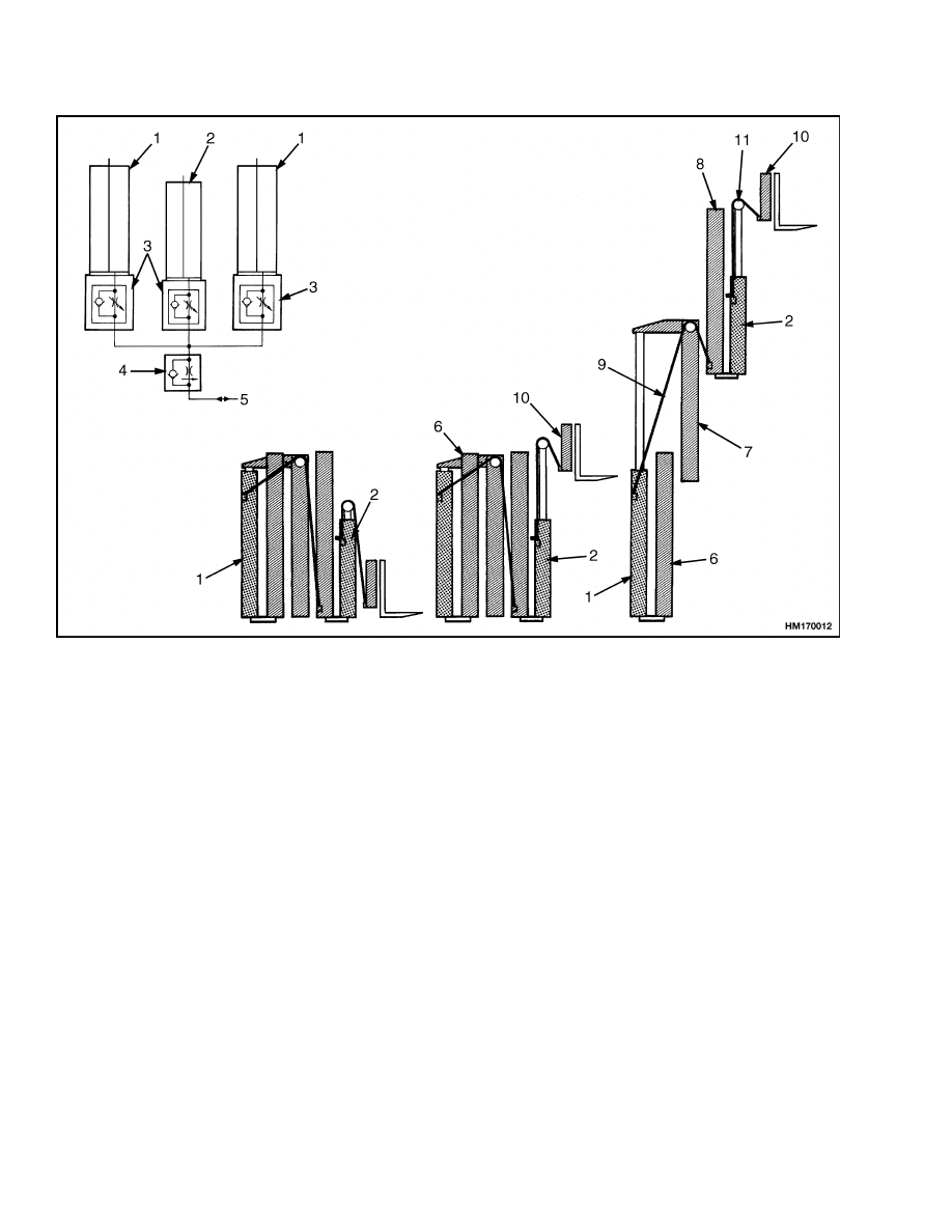
The three hydraulic cylinders are connected by hoses
and tubing as shown in Figure 12. To extend the
mast, oil from the main control valve flows to all
cylinders at the same time. The free-lift cylinder ex-
tends first because it lifts the least amount of weight.
The free-lift cylinder raises the carriage to the top
of the inner weldment. After the free-lift cylinder
reaches the end of its stroke, the main lift cylinders
begin to extend. As the main lift cylinders extend,
the intermediate weldment is raised by the lift cylin-
ders and the inner weldment is raised by the lift
chains.
During lowering, the main lift cylinders lower first
because they have a greater load. After the main lift
cylinders have retracted, the free-lift cylinder lowers.
All oil from the lift cylinders flows through the low-
ering control valves to the hydraulic tank.
The free-lift cylinder must have 0.5 liter (0.5 qt) of oil
above the piston. This oil provides a hydraulic cush-
ion when the cylinder reaches the top of its stroke. A
check valve and orifice system in the bottom of the
rod assembly keeps the oil at the correct level. When
the cylinder is fully extended, excess oil above the
piston is forced through the check valve. This ac-
tion allows the cylinder to fully extend. See Cylinder
Cushion During Lifting Sequence.
Each main lift cylinder has an orifice system and a
check valve in the bottom of the rod assembly. When
the cylinder is fully extended, excess oil between the
rod end and the gland is forced through the check
valve. This action allows the cylinder to fully extend.
The orifice system provides a hydraulic cushion when
the cylinder reaches the bottom of its stroke. See
Cylinder Cushion During Lowering Sequence.
9
Three-Stage Mast, Full Free-Lift (FFL)
4000 SRM 521
1.
LIFT CYLINDER
2.
FREE-LIFT CYLINDER
3.
LOWERING CONTROL VALVE (INTERNAL)
4.
LOWERING CONTROL VALVE (EXTERNAL)
5.
TO/FROM MAIN CONTROL VALVE
6.
OUTER WELDMENT
7.
INTERMEDIATE WELDMENT
8.
INNER WELDMENT
9.
MAIN LIFT CHAIN
10. CARRIAGE
11. FREE-LIFT CHAIN
Figure 12. Operation of Three-Stage Mast, Full Free-Lift (FFL)
10
4000 SRM 521
Cylinder Cushion During Lifting Sequence
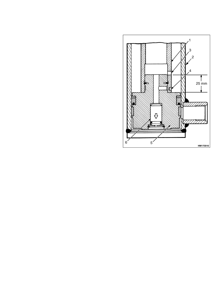
Cylinder Cushion During Lifting Sequence
There is hydraulic oil on the rod side of the piston
of the free-lift cylinder. As the cylinder rod extends,
the hydraulic oil on the rod side flows to the base of
the cylinder through the larger hole and the internal
check valve. When the cylinder rod extends to the
last 25 mm (1 in.) of its stroke, the retainer at the top
of the cylinder closes the larger hole. During the last
25 mm (1 in.) of the cylinder stroke, the remainder
of the hydraulic oil must flow through the orifice to
the internal check valve. This action increases the
hydraulic pressure so the main lift cylinders begin to
extend. See Figure 13.
The hydraulic action at the end of the free-lift stroke
provides a cushion effect for the free-lift cylinder and
a smooth transition between the free-lift phase and
the channel extension phase. All masts with a free-
lift cylinder in this section use this design.
1.
CYLINDER ROD
2.
CYLINDER SHELL
3.
LARGER HOLE
4.
ORIFICE (SMALLER HOLE)
5.
PISTON
6.
INTERNAL CHECK VALVE
Figure 13. Free-Lift Cylinder Piston
11
Cylinder Cushion During Lowering Sequence
4000 SRM 521
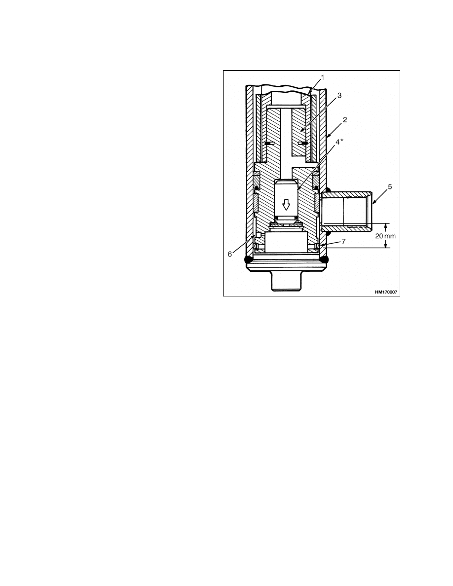
Cylinder Cushion During Lowering Sequence
NOTE:
Internal check valve is not used on the two-
stage FFL mast.
When the main lift cylinders retract, the hydraulic oil
flows out of the cylinder through the hydraulic port
until the piston seal moves past hydraulic port. Dur-
ing the last 20 mm (0.79 in.) of the retraction stroke,
the hydraulic oil must flow through the orifice. See
Figure 14. This action causes the cylinder rod to
move much more slowly at the end of the retraction
stroke. This cushion effect prevents a sudden stop
at the end of the lowering sequence, which causes
smoother operation during lowering. All masts in
this section use this design in the main lift cylinders.
1.
CYLINDER ROD
2.
CYLINDER SHELL
3.
PISTON
4.
INTERNAL CHECK
VALVE
5.
HYDRAULIC PORT
6.
ORIFICE
7.
PISTON SEAL
Figure 14. Main Lift Cylinder Piston
12


TECHNICAL PUBLICATIONS
4000 SRM 521
5/04
(11/03)(3/03)(1/02)(5/01)(2/01)(6/96)(10/95)(3/95)(11/94)(7/94)(3/94) Printed in United Kingdom
Document Outline
- toc
Wyszukiwarka
Podobne podstrony:
897067 1400SRM0285 (05 2004) UK EN
910460 1600SRM0258 (05 2004) UK EN
1467764 8000SRM0738 (05 2004) UK EN
897988 4000SRM0660 (05 1997) UK EN
897390 0100SRM0449 (05 2004) UK EN
897989 4000SRM0661 (02 2004) UK EN
1553986 8000SRM1083 (05 2004) UK EN
897104 0100SRM0322 (05 2004) UK EN
więcej podobnych podstron