DRIVE AXLE, SPEED
REDUCER, AND
DIFFERENTIAL
E/J1.25-1.75XL (E/J25-35XL) [C114];
E/J2.00-3.00XL (E/J40-60XL) [B168, C108];
E2.00-3.20XM (E45-65XM, E45-65XM
2
) [F108];
N30XMH, N30XMH
2
[C210];
E2.00-3.20XM (E45-65Z) [G108];
V30ZMD [D210]
PART NO. 897067
1400 SRM 285

SAFETY PRECAUTIONS
MAINTENANCE AND REPAIR
• When lifting parts or assemblies, make sure all slings, chains, or cables are correctly
fastened, and that the load being lifted is balanced. Make sure the crane, cables, and
chains have the capacity to support the weight of the load.
• Do not lift heavy parts by hand, use a lifting mechanism.
• Wear safety glasses.
• DISCONNECT THE BATTERY CONNECTOR before doing any maintenance or repair
on electric lift trucks. Disconnect the battery ground cable on internal combustion lift
trucks.
• Always use correct blocks to prevent the unit from rolling or falling. See HOW TO PUT
THE LIFT TRUCK ON BLOCKS in the Operating Manual or the Periodic Mainte-
nance section.
• Keep the unit clean and the working area clean and orderly.
• Use the correct tools for the job.
• Keep the tools clean and in good condition.
• Always use HYSTER APPROVED parts when making repairs. Replacement parts
must meet or exceed the specifications of the original equipment manufacturer.
• Make sure all nuts, bolts, snap rings, and other fastening devices are removed before
using force to remove parts.
• Always fasten a DO NOT OPERATE tag to the controls of the unit when making repairs,
or if the unit needs repairs.
• Be sure to follow the WARNING and CAUTION notes in the instructions.
• Gasoline, Liquid Petroleum Gas (LPG), Compressed Natural Gas (CNG), and Diesel fuel
are flammable. Be sure to follow the necessary safety precautions when handling these
fuels and when working on these fuel systems.
• Batteries generate flammable gas when they are being charged. Keep fire and sparks
away from the area. Make sure the area is well ventilated.
NOTE:
The following symbols and words indicate safety information in this
manual:
WARNING
Indicates a condition that can cause immediate death or injury!
CAUTION
Indicates a condition that can cause property damage!

Drive Axle, Speed Reducer, and Differential
Table of Contents
TABLE OF CONTENTS
General ...............................................................................................................................................................
Description .........................................................................................................................................................
Drive Axle, Speed Reducer, and Differential Repair........................................................................................
Drive Axle, Remove .......................................................................................................................................
Drive Axle, Disassemble ...........................................................................................................................
Speed Reducer and Differential, Disassemble.........................................................................................
Clean ..............................................................................................................................................................
Inspect ............................................................................................................................................................
Assemble ........................................................................................................................................................
Speed Reducer and Differential, Assemble..............................................................................................
Input Gear Assembly, Install ...............................................................................................................
New Pinion Assembly, Install...............................................................................................................
Drive Axle, Assemble ................................................................................................................................
Drive Axle Assembly, Install .........................................................................................................................
Torque Specifications .........................................................................................................................................
Wheel Nuts.....................................................................................................................................................
Axle Shaft Capscrews ....................................................................................................................................
Axle Hangers to Frame .................................................................................................................................
Back Plate to Axle Mount Capscrews...........................................................................................................
Wheel Cylinder Capscrews ...........................................................................................................................
Ring Gear to Differential Case .....................................................................................................................
Differential Case Halves ...............................................................................................................................
Bearing Cap Capscrews ................................................................................................................................
Retainer Capscrews .......................................................................................................................................
Axle Housing to Differential Housing ..........................................................................................................
Pinion Nut......................................................................................................................................................
Speed Reducer Housing to Differential Housing .........................................................................................
Traction Motor to Transmission....................................................................................................................
Troubleshooting..................................................................................................................................................
This section is for the following models:
E/J1.25-1.75XL (E/J25-35XL) [C114];
E/J2.00-3.00XL (E/J40-60XL) [B168, C108];
E2.00-3.20XM (E45-65XM, E45-65XM
2
) [F108];
N30XMH, N30XMH
2
[C210];
E2.00-3.20XM (E45-65Z) [G108];
V30ZMD [D210]
©2004 HYSTER COMPANY
i

"THE
QUALITY
KEEPERS"
HYSTER
APPROVED
PARTS

1400 SRM 285
Description
General
This section has the description and repair procedures for the differential, speed reducer, drive axle, wheel
bearings, and mounts for the axle housing.
Description
WARNING
The lift truck must be put on blocks for some
types of maintenance and repair.
See the
Operating Manual or the service manual sec-
tion Periodic Maintenance, for your lift truck
model, for the procedures to put the lift truck
on blocks. The removal of the following assem-
blies will cause large changes in the center of
gravity:
• Attachment
• Mast
• Drive axle
• Battery
• Counterweight
When the lift truck is put on blocks, put addi-
tional blocks in the following positions:
a. Before removing the mast and drive axle,
put blocks under the counterweight so the
lift truck cannot tip backward.
b. Before removing the battery or counter-
weight, put blocks under the mast assem-
bly so the lift truck cannot tip forward.
Put the lift truck on blocks only if the surface
is solid, even, and level. Make sure that any
blocks used to support the lift truck are solid,
one-piece units.
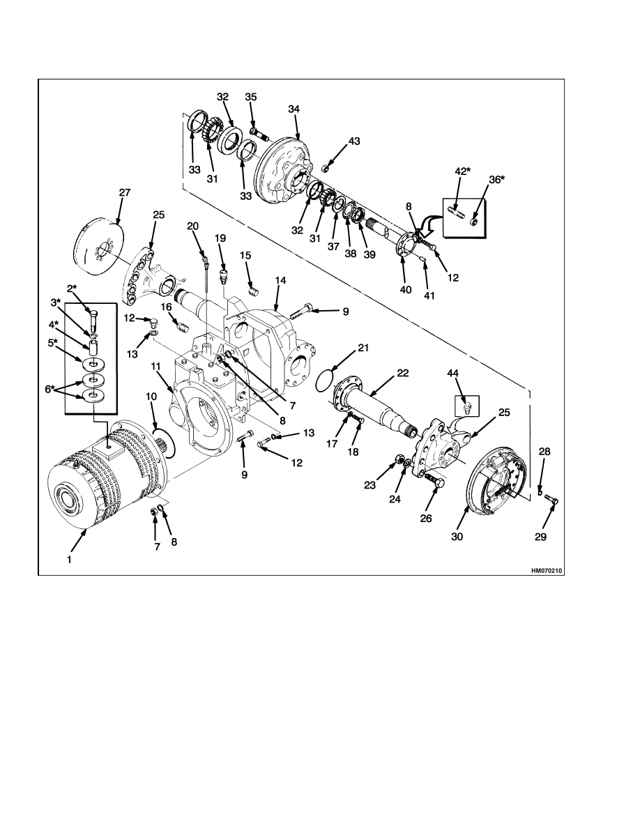
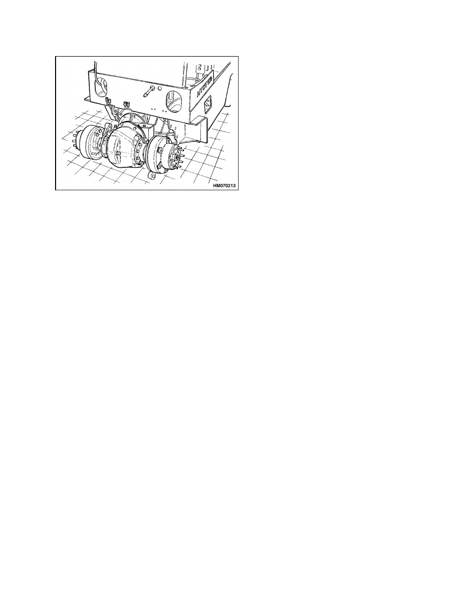
The mount brackets for the drive axle housing are
fastened to the frame of the lift truck with six bolts
on the E/J1.25-1.75XL (E/J25-35XL) (C114) models
and eight bolts on the E2.00-3.00XL (E40-60XL)
(C108),
E2.00-3.20XM (E45-65XM, E45-65XM
2
)
(F108), E2.00-3.20XM (E45-65Z) (G108), J2.00-3.00
(J40-60XL) (B168), N30XMH
2
, and N30XMH (C210),
V30ZMD (D210) models. See Figure 1. The outer
ends of the axle housings are the spindles for the
wheel bearings.
The cups for the tapered roller
bearings for the wheel bearings are pressed into the
wheel hubs. The nut on the end of the spindle holds
and adjusts the preload on the wheel bearings. The
axle shafts are fastened to the hubs by capscrews.
Studs and nuts fasten the wheel to the hub and
brake drum. The back plate and brake assemblies
are fastened to the mount brackets for the axle
housing.
The speed reducer and differential are a single as-
sembly. See Figure 5. The speed reducer has a gear
that engages the splines on the shaft of the traction
motor. A second speed reducer gear is fastened to the
pinion shaft for the differential.
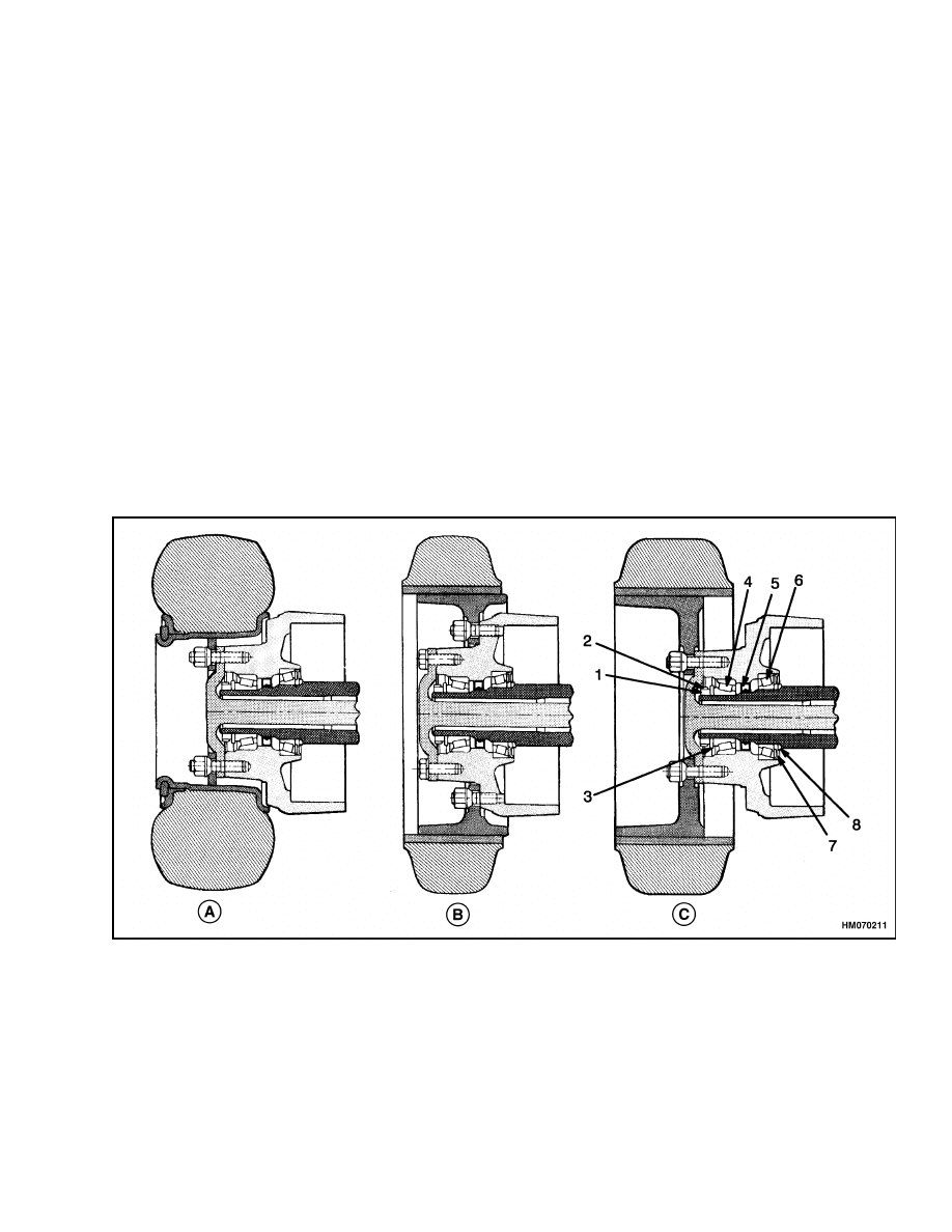
There are three configurations of drive wheel mounts
used on the E/J1.25-1.75XL (E/J25-35XL) (C114) se-
ries of lift trucks because of the variations in tires
that are available:
E1.25-1.75XL (E25-35XL)
Standard solid tires
Wide tread solid tires
J1.25-1.75XL (J25-35XL)
Pneumatic tires
Solid tires shaped like pneumatic tires
The pneumatic tires are available in standard and
wide tread configurations, but the mount to the drive
axle is the same.
The methods used to fasten the drive wheels to the
hub are different for the three configurations. See
Figure 2. When the drive axle is disassembled or
assembled, small changes in the procedure must be
made for the differences in the axles.
1
Description
1400 SRM 285
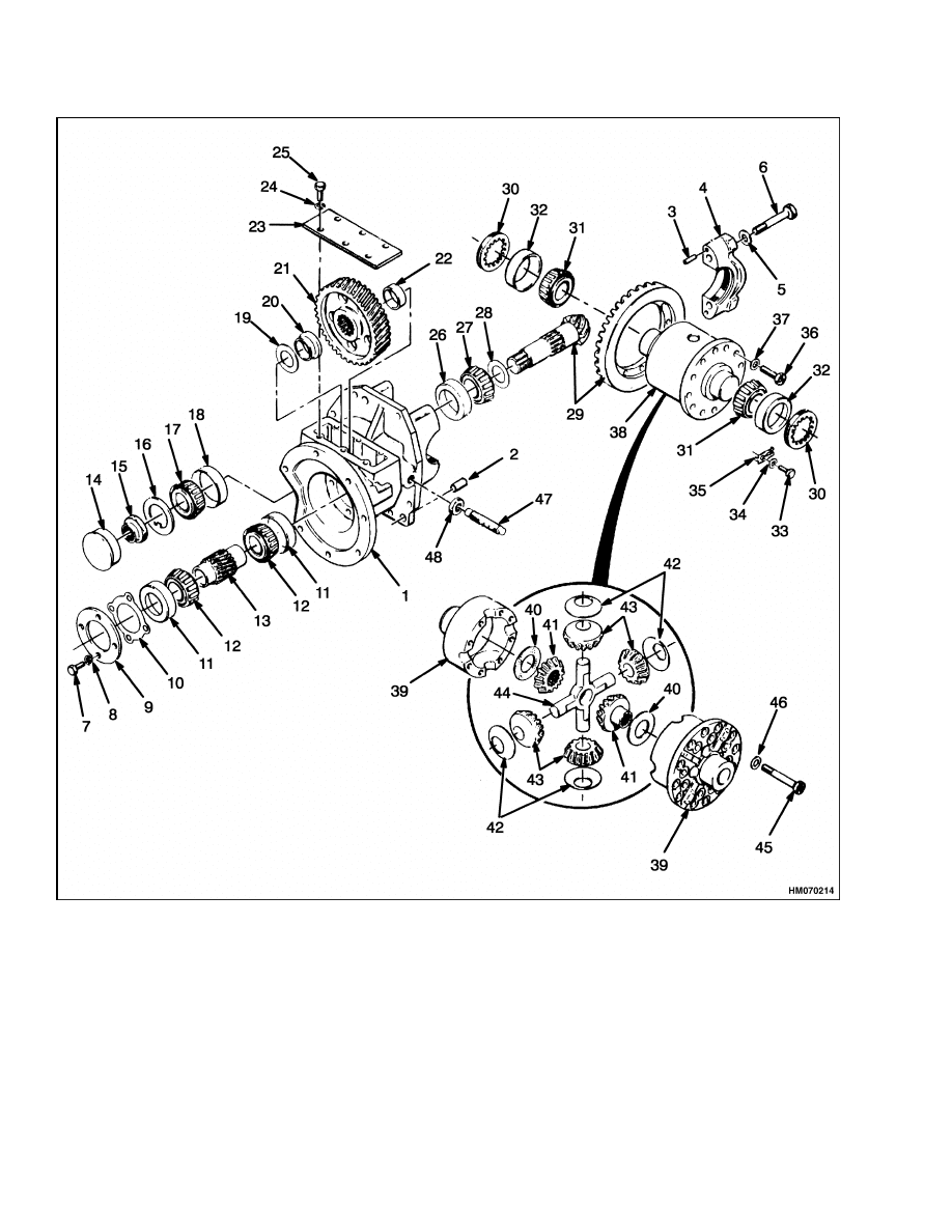
Figure 1. Drive Axle Assembly
2
1400 SRM 285
Description
Legend for Figure 1
NOTE: E2.00-3.20XM (E45-65XM, E45-65XM
2
) (F108), AND E2.00-3.20XM (E45-65Z) (G108) DRIVE AXLES
SHOWN. OTHER MODELS ARE SIMILAR. WHEEL CONFIGURATIONS FOR E/J1.25-1.75XL (E/J25-35XL)
(C114) ARE SHOWN IN FIGURE 2.
1.
TRACTION MOTOR
2.
CAPSCREW, MOTOR MOUNT*
3.
WASHER*
4.
SPACER*
5.
WASHER*
6.
WASHER*
7.
NUT
8.
LOCKWASHER
9.
CAPSCREW
10. O-RING
11. SPEED REDUCER AND
DIFFERENTIAL
12. CAPSCREW
13. WASHER
14. AXLE HOUSING
15. PLUG
16. PLUG
17. WASHER
18. CAPSCREW
19. BREATHER
20. DIPSTICK
21. O-RING
22. SPINDLE
23. NUT
24. WASHER
25. HANGER
26. CAPSCREW
27. LH BRAKE
28. LOCKWASHER
29. CAPSCREW
30. RH BRAKE
31. BEARING CONE
32. BEARING CUP
33. OIL SEAL
34. BRAKE DRUM
35. STUD
36. WHEEL/AXLE NUT*
37. WASHER
38. LOCKWASHER
39. NUT
40. AXLE
41. DOWEL PIN
42. STUD*
43. WHEEL NUT
44. GREASE FITTING
*NOT USED ON E2.00-3.20XM (E45-65XM, E45-65XM
2
) (F108), E2.00-3.20XM (E45-65Z) (G108), N30XMH AND
N30XMH
2
(C210), V30ZMD (D210)
A. PNEUMATIC
B. STANDARD
C. WIDE TREAD
1.
LOCK NUT
2.
LOCK PLATE
3.
WASHER
4.
OUTER BEARINGS
5.
OIL SEAL
6.
INNER BEARING
7.
SEAL
8.
SPACER
Figure 2. Drive Wheel Mounting E/J1.25-1.75XL (E/J25-35XL) (C114)
3
Drive Axle, Speed Reducer, and Differential Repair
1400 SRM 285
Drive Axle, Speed Reducer, and Differential Repair
DRIVE AXLE, REMOVE
WARNING
The lift truck must be put on blocks for some
types of maintenance and repairs.
See the
Operating Manual or the service manual sec-
tions Periodic Maintenance, for your lift truck
model, for the procedures to put the lift truck
on blocks. The removal of the following assem-
blies will cause large changes in the center of
gravity:
• Attachment
• Mast
• Drive axle
• Battery
• Counterweight
When the lift truck is put on blocks, put addi-
tional blocks in the following positions:
a. Before removing the mast and drive axle,
put blocks under the counterweight so the
lift truck cannot tip backward.
b. Before removing the battery or counter-
weight, put blocks under the mast assem-
bly so the lift truck cannot tip forward.
Put the lift truck on blocks only if the surface
is solid, even, and level. Make sure that any
blocks used to support the lift truck are solid,
one-piece units.
1.
Remove the battery as described in your vehicle’s
Periodic Maintenance SRM.
2.
Remove the mast assembly as described in your
vehicle’s Mast SRM. Drain the oil from the dif-
ferential. Remove the floor plates.
NOTE:
The drive axle can be removed with the trac-
tion motor as one unit. Many service persons remove
the traction motor before the drive axle is removed
to reduce the weight of the unit. See your vehicle’s
Frame SRM for procedures to remove the traction
motor. The procedure in this section will describe re-
moval of the drive axle after the traction motor has
been removed.
3.
Disconnect the brake lines to the wheel cylinders.
Put caps on the open fittings.
4.
E/J1.25-1.75XL (E/J35-35XL) (C114).
Discon-
nect the hand lever assembly for the parking
brake from the cowl. Loosen the retainer that
holds the hydraulic lines and cables near the
floor plate. Carefully slide the hand lever as-
sembly and cables past the hydraulic lines and
electric wires so that the hand lever assembly
and cables can be removed with the drive axle.
E/J2.00-3.00XL (E/J40-60XL) (B168, C108). Dis-
connect the parking brake cables at the brakes.
E2.00-3.20XM (E45-65XM, E45-65XM
2
) (F108),
E2.00-3.20XM (E45-65Z) (G108), N30XMH, and
N30XMH
2
(C210), V30ZMD (D210). Disconnect
the return spring from the park brake pedal. Re-
move the park brake pedal. Disconnect the park
brake assembly from the frame. Do not remove
the mounting bolts from the park brake assem-
bly. Remove the nuts and washers so that the
bolts will keep the park brake assembly in one
unit. After the park brake assembly has been re-
moved from the frame bracket, put the nuts and
washers on the bolts.
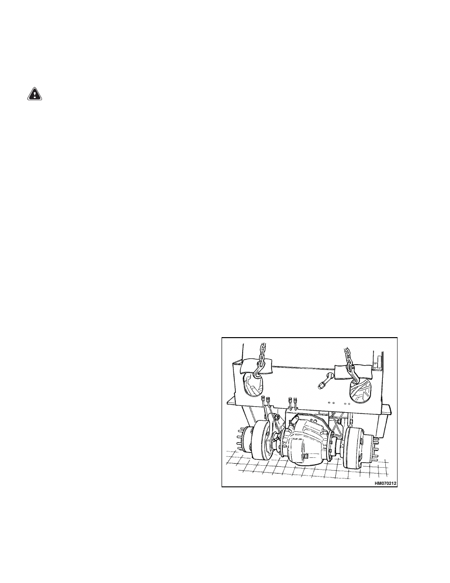
5.
Remove the drive wheels and lower the lift truck
so that the drive axle and the front of the frame is
on the floor. (The steering wheels are on the floor
and hold the end of the frame with the counter-
weight.) See Figure 3 and Figure 4.
Figure 3. Lower Drive Axle to Surface
4
1400 SRM 285
Drive Axle, Speed Reducer, and Differential Repair
Figure 4. Remove Drive Axle From Lift Truck
6.
Remove the 7/8 × 14 UNF bolts that hold the axle
mounts to the frame. Turn the axle mounts for-
ward so that there is additional clearance for re-
moval of the drive axle.
NOTE:
Some early models of the electric XL series of
lift trucks have M20 × 2.5 × 80 bolts instead of 7/8 ×
14 UNF bolts.
7.
Remove the mounting bolts for the hydraulic fil-
ter. With the hoses still attached to the filter,
move the filter to improve access to the mounting
bolt for the speed reducer. Remove the mount-
ing bolt that is located on the top of the speed
reducer/differential assembly. See Figure 1.
8.
Slide the drive axle assembly from the lift truck.
Use a crane and slings to move the drive axle to
a work space.
Drive Axle, Disassemble
1.
Remove the capscrews that hold the axle shaft to
the hub. There are two holes with threads in the
flange of the axle shaft. Put capscrews (M12 ×
1.75) in these holes to loosen the axle shaft from
the hub.
2.
Bend the lock plate so that the nut can be re-
moved from the axle spindle. Remove the nut,
lock plate, washer, and bearing cone. Carefully
slide the hub and brake drum assembly from the
spindle. Keep the spindle in the center of the hub
and brake drum assembly during removal so that
the oil seal in the hub is not damaged. Do not per-
mit oil or grease to get on the brake shoes.
3.
Remove the inner bearing cone from the spindle.
E/J1.25-1.75XL (E/J25-35XL) (C114) models also
have a spacer between the grease seal and the
shoulder of the wheel spindle.
4.
If the brakes must be repaired, disassemble the
brake assembly as described in your vehicle’s
Brakes SRM. If disassembly of the brakes is not
required, slide the brake assembly and the axle
mount bracket from the axle spindle.
5.
The axle spindles are not normally removed from
the differential housing. If repairs are necessary,
remove the 16 M12 × 1.75 × 35 capscrews that
hold the axle spindles to the differential housing.
Remove the axle spindles.
6.
Remove the six M10 × 1.5 × 30 capscrews and
washers and the two M10 × 1.5 × 40 capscrews
and washers from the bottom of the differential
housing. Remove the speed reducer and differen-
tial assembly from the differential housing.
Speed Reducer and Differential,
Disassemble
1.
Remove the access plate from the top of the speed
reducer. See Figure 5. Use a small pry bar to
remove the hub cap from the end of the pinion
shaft.
2.
Disassemble only the parts of the speed reducer
and differential that must be repaired. If the ring
gear and pinion are not to be replaced, but parts
of the differential must be replaced, check the
contact pattern before disassembly. The pattern
and the gear clearance are used as references for
assembly. See the Assemble section for the pro-
cedures.
3.
Loosen or remove the thrust screw for the ring
gear. Remove the lock plates for the adjusting
nuts. Remove the inner bearing caps, adjust-
ing nuts, bearing cups, and differential assembly.
Make sure you do not change the parts from the
right and left sides of the differential.
4.
Use a sharp punch to raise the lock detent from
the slot in the pinion shaft. Raise the lock de-
tent as carefully as possible so there is minimum
damage to the threads on the pinion shaft when
the special lock nut is removed.
5
Drive Axle, Speed Reducer, and Differential Repair
1400 SRM 285
Figure 5. Speed Reducer and Differential
6

1400 SRM 285
Drive Axle, Speed Reducer, and Differential Repair
Legend for Figure 5
1.
SPEED REDUCER HOUSING
2.
DOWEL PIN
3.
DOWEL PIN
4.
INNER BEARING CAP
5.
WASHER
6.
CAPSCREW
7.
CAPSCREW
8.
LOCKWASHER
9.
BEARING RETAINER
10. SHIM
11. OUTER BEARING CUP
12. BEARING CONE
13. INPUT GEAR
14. HUB CAP
15. SPECIAL LOCK NUT
16. WASHER
17. BEARING CONE
18. BEARING CUP
19. SHIM
20. SPACER
21. SPEED REDUCER GEAR
22. SPACER
23. PLATE
24. LOCKWASHER
25. CAPSCREW
26. BEARING CUP
27. BEARING CONE
28. SHIM
29. RING GEAR AND PINION
30. ADJUSTING NUT
31. BEARING CONE
32. BEARING CUP
33. CAPSCREW
34. LOCKWASHER
35. LOCK PLATE
36. PLACEBOLT
37. WASHER
38. DIFFERENTIAL
39. DIFFERENTIAL HOUSING
40. WASHER
41. SIDE GEAR
42. THRUST WASHER
43. SPIDER GEAR
44. CROSS
45. CAPSCREW
46. WASHER
47. THRUST SCREW
48. JAM NUT
5.
Use a piece of soft metal (copper or aluminum)
to prevent the speed reducer gear from turning
when the special lock nut is removed. Use the
soft piece of metal between the speed reducer
gears or between the speed reducer gear and the
housing. Remove the special lock nut. This spe-
cial lock nut is tightened to 340 N•m (250 lbf ft).
Discard the special lock nut.
6.
Remove the special washer with the key tab. Use
a brass hammer to remove the pinion from the
transmission case. The speed reducer gear and
spacer will slide from the pinion shaft as it is re-
moved from the speed reducer housing. Make a
note of the shim arrangement between the bear-
ing and the spacer.
7.
Remove the speed reducer gear and spacer from
the speed reducer housing.
8.
Remove the spacer from the pinion shaft. Use a
press to remove the bearing cone from the pinion.
Make a note of the shim arrangement between
the bearing cone and the pinion.
9.
Use a press or a puller to remove the bearing
cones from the differential case.
10. Remove the ring gear. Remove the 12 7/16 UNF
× 1 inch bolts and the special hardened washers.
Do not use a press or a hammer to remove the
ring gear. Heat the differential in hot oil or water
to 82 to 100 C (180 to 212 F) to loosen the ring
gear.
11. Disassemble the differential. Remove the eight
3/8 UNF × 3-1/2 inch capscrews and washers and
separate the differential case. Remove the cross,
spider gears, and axle gears.
12. Remove the four M8 × 1.25 × 25 capscrews and
washers. Remove the bearing retainer, shims,
outer bearing cup, and input gear assembly.
Make a note of the shim arrangement. If the
inner bearing is damaged, use a puller to remove
the inner bearing cup from the speed reducer
housing.
7

Drive Axle, Speed Reducer, and Differential Repair
1400 SRM 285
CLEAN
WARNING
Always wear safety glasses.
Cleaning solvents may be flammable and toxic
and can cause severe skin irritation. When us-
ing cleaning solvents, always comply with the
solvent manufacturer’s recommended safety
precautions.
Compressed air can move particles so that they
cause injury to the user or to other personnel.
Make sure that the path of the compressed air
is away from all personnel.
Wear protective
goggles or a face shield to prevent injury to the
eyes.
Clean the parts of the drive axle with solvent. Dry
the parts with compressed air.
INSPECT
1.
Check the pinion and ring gear for wear. Inspect
the spider gears and axle gears for worn teeth.
Inspect the cross for wear where the gears turn.
The cross and the holes for the cross in the dif-
ferential case must fit tightly.
2.
Inspect the bearings and seals for wear or dam-
age. If bearings are damaged, replace bearing
cups.
3.
The mount brackets must turn freely on the axle
housings. The splines for the axle shafts must
not be damaged.
ASSEMBLE
Speed Reducer and Differential, Assemble
Input Gear Assembly, Install
1.
If removed, install the inner bearing cup in the
end of the bore in the speed reducer housing. Use
a press to install bearing cones on each end of the
input gear. Install the input gear and bearings
into the speed reducer housing. See Figure 6.
Install the outer bearing cup.
2.
Install the shims and the bearing retainer. In-
stall the four M8 x 1.25 x 25 capscrews and
washers.
Tighten the capscrews to 19 N•m
(14 lbf ft). Check the bearing clearance. Add
or remove shims to adjust for zero bearing
clearance. The input gear must turn smoothly
with a maximum rotation torque of 0.133 N•m
(1.2 lbf in).
New Pinion Assembly, Install
If the ring gear and pinion are worn or damaged, they
must be replaced as a set. The ring gear and pin-
ion must have the same reference numbers. When
the pinion bearings are replaced or the ring gear and
pinion are replaced, the shim arrangement must be
adjusted for the new parts. Service persons must of-
ten make more than one adjustment before the clear-
ances are correct. The speed reducer must be dis-
assembled for shim adjustment and then assembled
again for checks. The adjustments are correct when
the gear clearance and contact pattern between the
pinion and ring gear are correct and the preload on
the pinion bearings is correct.
CAUTION
Do not lock the special nut on the pinion shaft
until the adjustments of the pinion are com-
plete. The lock on the special nut will damage
the threads on the pinion shaft if the special
nut must be removed several times for adjust-
ments. If the threads are damaged on the pin-
ion shaft, the pinion and ring gear must be re-
placed.
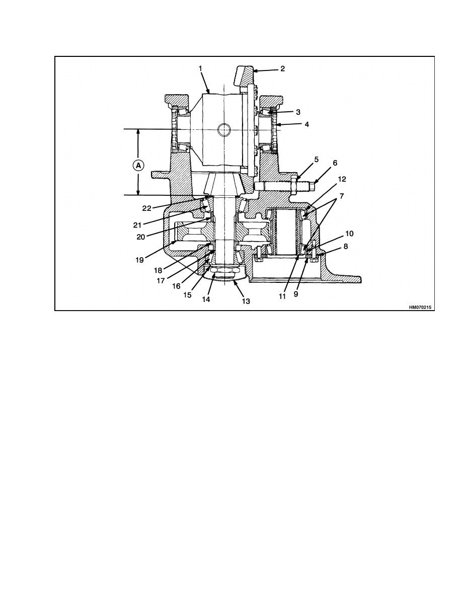
The dimension on the end of the pinion is the varia-
tion from the standard Gauge Distance. The Gauge
Distance is the distance from the center of the ring
gear to the bearing shoulder behind the pinion gear.
Shims must be added between the pinion and the
bearing to adjust for manufacturing tolerances.
8
1400 SRM 285
Drive Axle, Speed Reducer, and Differential Repair
A. THE GAUGE DISTANCE IS 129.20 mm (5.087 in.) PLUS OR MINUS THE VARIATION SHOWN ON THE
END OF THE PINION. THE ADJUSTMENT MUST BE WITHIN ±0.0254 mm (0.001 in.) OF THE ACTUAL
DISTANCE.
1.
DIFFERENTIAL ASSEMBLY
2.
RING GEAR
3.
BEARING
4.
ADJUSTER NUT
5.
JAM NUT
6.
THRUST SCREW
7.
BEARING (2)
8.
SHIM
9.
RETAINER
10. OUTER BEARING CUP
11. INPUT GEAR
12. INNER BEARING CUP
13. HUB CAP
14. SPECIAL NUT
15. WASHER (KEYED)
16. BEARING
17. SHIM
18. SPACER
19. GEAR
20. SPACER
21. BEARING
22. SHIMS
Figure 6. Differential and Speed Reducer Assembly
9
Drive Axle, Speed Reducer, and Differential Repair
1400 SRM 285
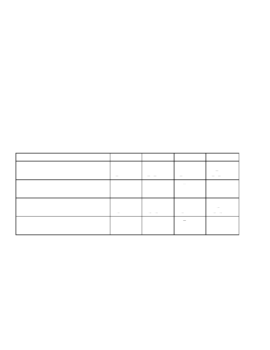
Look at the number on the pinion that was removed.
Subtract the variation number that is on the new pin-
ion. The remainder is the amount of shim thickness
that must be adjusted from the shim set on the pin-
ion that was removed. See Table 1 for examples. In
example 3 you can see that a negative number shows
that shims must be added. Examples 1, 2, and 4 show
that shims must be subtracted from the original shim
set. Use this shim set as a reference. The final ad-
justment is according to the contact pattern on the
ring gear teeth. See Figure 14.
1.
If the bearing cups for the pinion were removed,
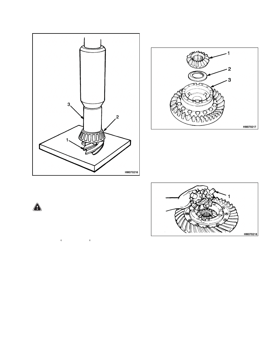
install them in the speed reducer housing.
2.
Install the shims on the pinion and use a press
to install the bearing cone. Install the spacer on
the pinion shaft. See Figure 7.
3.
Put the speed reducer gear and spacer in the
speed reducer housing. Install the pinion in the
speed reducer housing and slide the speed re-
ducer gear and spacer on the pinion shaft when
it is installed.
4.
Install the shims on the pinion shaft that con-
trol the preload on the pinion bearings. Install
the bearing cone, washer with the key tab, and
special lock nut. Use a soft piece of metal (cop-
per or aluminum) to prevent the speed reducer
gear from turning. Tighten the special lock nut
to 340 N•m (250 lbf ft). Do not lock the special
nut at this time.
5.
Check the rotating torque of the pinion and speed
reducer assembly. The correct rotating torque is
1.13 to 2.26 N•m (10 to 20 lbf in). Lightly hit
the outside of the housing to adjust the bearings
in their seats. Add or remove shims between the
spacer and the bearing cone to adjust the bearing
preload.
Table 1. Adjustment of Shims for Pinion Assembly
Examples
1
2
3
4
If the numbers are given in inches:
Number on OLD GEAR
Number on NEW GEAR
+0.012
(+0.010)
+0.012
( 0.010)
+0.010
(+0.012)
0.010
( 0.012)
Shims to be Removed from Old Set
+0.002 in.
+0.022 in.
0.002
in. (ADD
SHIMS)
+0.002 in.
If the numbers are given in millimeters:
Number on OLD GEAR
Number on NEW GEAR
+0.31
(+0.26)
+0.31
( 0.26)
+0.26
(+0.31)
0.26
( 0.31)
Shims to be Removed from Old Set
+0.005 mm
+0.57 mm
0.005
mm (ADD
SHIMS)
+0.05 mm
10
1400 SRM 285
Drive Axle, Speed Reducer, and Differential Repair
1.
PINION
2.
BEARING CONE
3.
PRESS TOOL
Figure 7. Use Press to Install Parts on Pinion
WARNING
Hot parts. Wear protective clothing and gloves
to prevent burns.
6.
If the ring gear was removed from the differen-
tial case, put the ring gear into hot oil or water
[82 to 100 C (180 to 212 F)] for approximately 10
minutes. Remove the ring gear from the liquid
and put it into position on the differential case.
Do not use a press or a hammer to install the ring
gear. Install the 12 7/16 UNF × 1 inch bolts and
the special hardened washers. Tighten the bolts
to 111 N•m (82 lbf ft). Make sure the ring gear
is in the correct position against the flange of the
differential case.
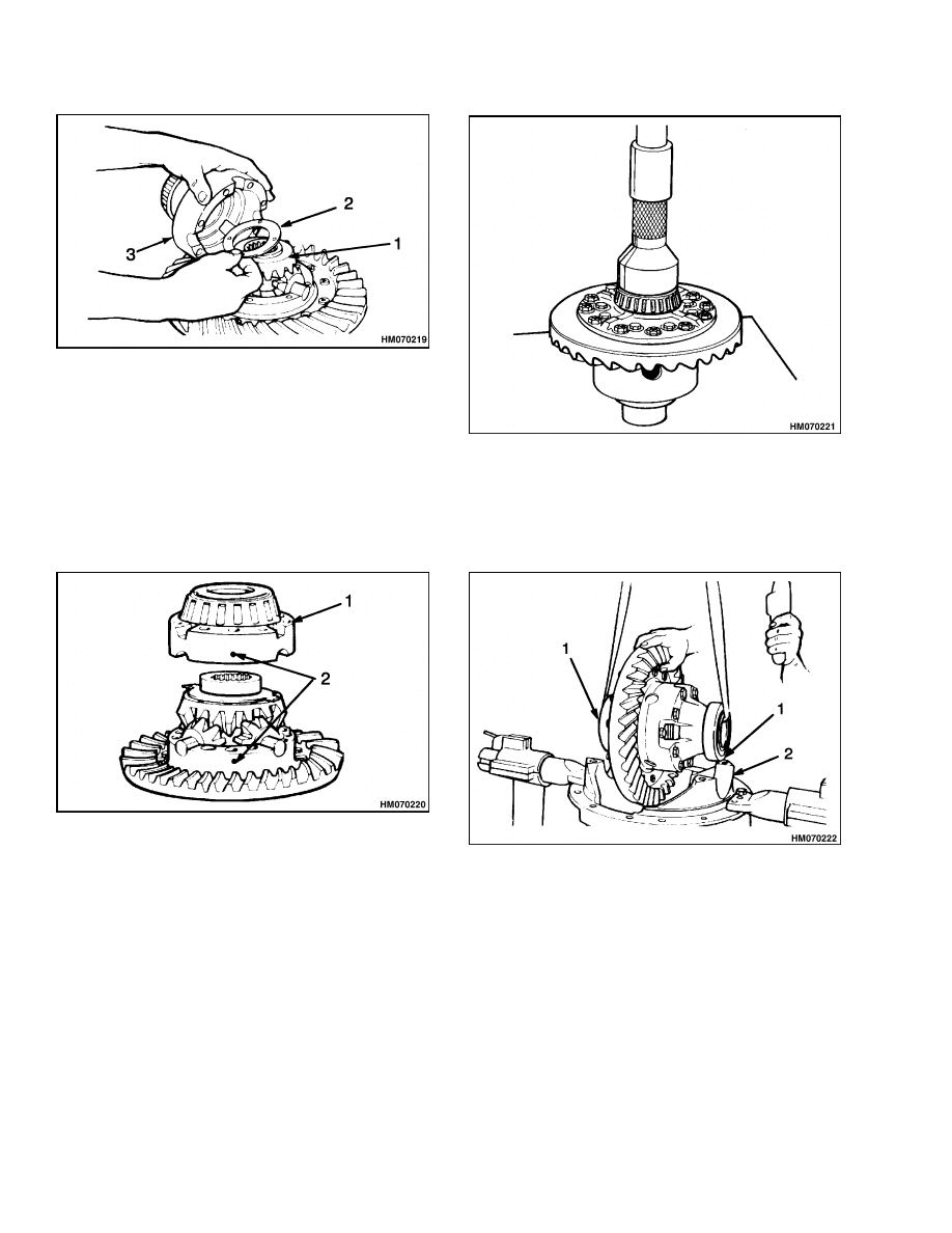
7.
Lubricate and install a thrust washer and side
gear in the differential case as shown in Figure 8.
1.
SIDE GEAR
2.
THRUST WASHER
3.
DIFFERENTIAL
CASE
Figure 8. Thrust Washer and Side Gear
Installation
8.
Lubricate and install the spider gears and thrust
washers on the cross and put the spider gear as-
sembly into the differential case. See Figure 9.
1.
SPIDER GEARS AND THRUST WASHERS
Figure 9. Spider Gears (Cross) and Thrust
Washers Installation
9.
Lubricate and install the second side gear and
thrust washer over the spider gear assembly as
shown in Figure 10.
11
Drive Axle, Speed Reducer, and Differential Repair
1400 SRM 285
1.
SIDE GEAR
2.
THRUST WASHER
3.
DIFFERENTIAL
CASE
Figure 10. Second Side Gear and Thrust
Washer Installation
10. Put the two halves of the differential case to-
gether (make sure the match marks are aligned)
and install the eight 3/8 UNF × 3-1/2 inch cap-
screws and washers. Tighten the capscrews to
50 N•m (37 lbf ft). See Figure 11.
1.
DIFFERENTIAL
CASE
2.
MATCH MARKS
Figure 11. Second Half of Differential Case
Installation
11. Use a press to install the bearing cones on each
side of the differential case. See Figure 12. Ap-
ply axle lubricant on the inner diameter of the
bearing cups and on both bearing cones that are
installed on the differential. Do not permit lubri-
cant on the outer diameter of the bearing cups or
the bearing bores of the differential housing.
Figure 12. Bearing Cones Installation
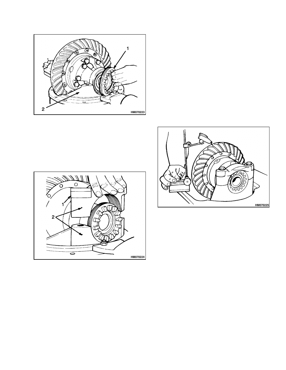
12. Install the differential assembly into the differ-
ential housing. The bearing cups must fit cor-
rectly into the bores of the housing. See Fig-
ure 13.
1.
BEARING CUP
2.
HOUSING
Figure 13. Differential Assembly Installation
Into Housing
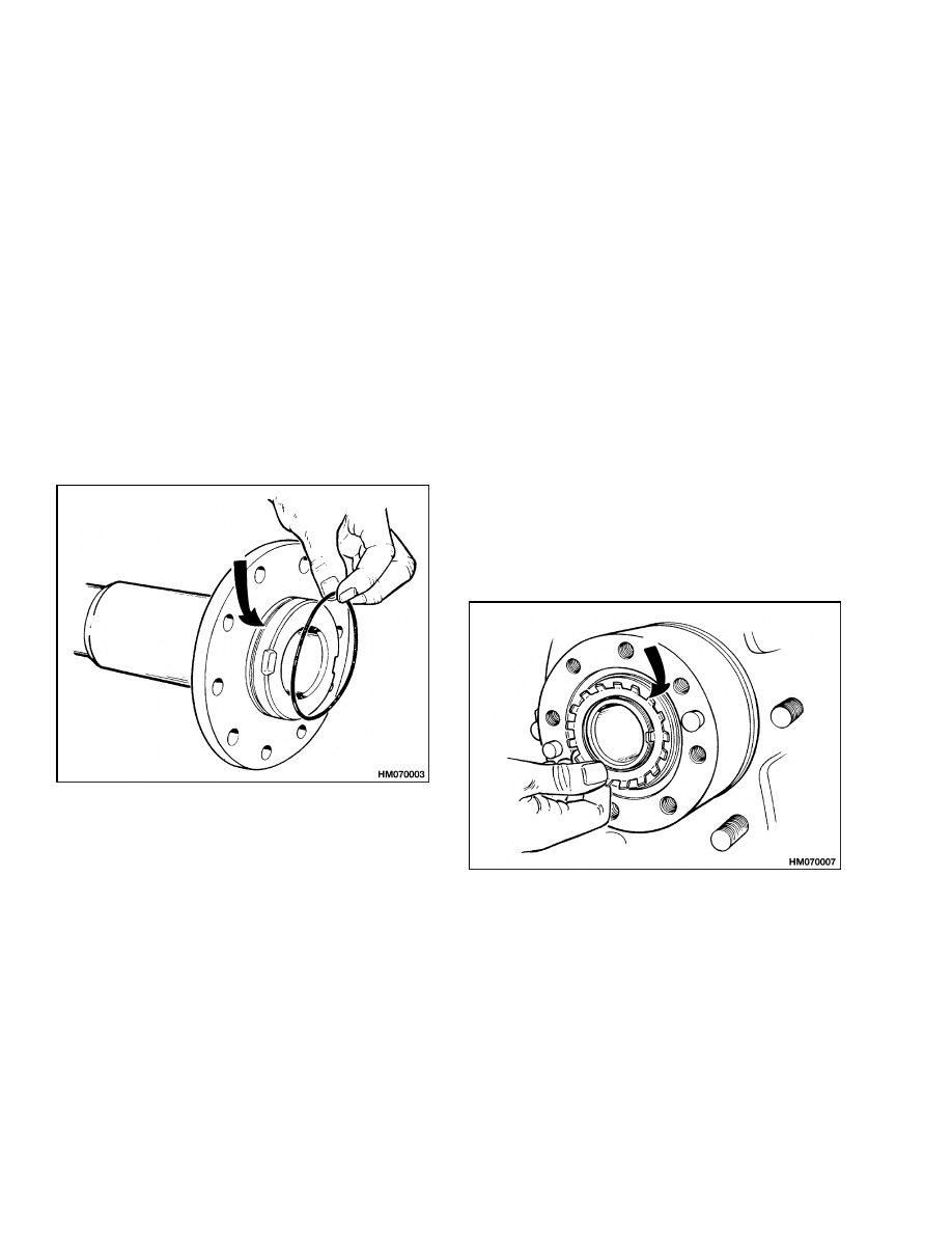
13. Install the two bearing adjusting nuts into posi-
tion in the housing bores. See Figure 14. Use
your hand to tighten each adjusting nut against
the bearing cup.
12
1400 SRM 285
Drive Axle, Speed Reducer, and Differential Repair
1.
ADJUSTING NUT
2.
HOUSING
Figure 14. Adjusting Nuts Installation
14. Align the marks on the bearing caps with the
marks on the housing. See Figure 15. The cap-
screws for the bearing caps should be tightened
only enough to hold the adjusting nuts in position
and allow them to be rotated for adjustment.
1.
BEARING CAP
2.
MATCH MARKS
Figure 15. Bearing Caps Installation
15. Tighten the adjusting nuts to 14 N•m (10 lbf ft) to
remove the clearance between the adjusting nuts
and the bearings. Make sure there is clearance
between the ring gear and the pinion. Loosen
an adjusting nut until there is zero clearance (no
preload) between the bearings and the adjusting
nuts. Tighten both adjusting nuts two notches
more than zero clearance to apply the correct
preload on the bearings.
16. Check the clearance between the ring gear and
pinion. The ring gear and pinion must have a
clearance of 0.13 to 0.20 mm (0.005 to 0.008 in.).
Use the adjusting nuts to move the ring gear to-
wards or away from the ring gear to increase
or decrease the clearance. Loosen one adjusting
nut the same amount as the other adjusting nut
is tightened to adjust the clearance between the
ring gear and pinion. When the clearance is cor-
rect, tighten the capscrews for the bearing caps
to 95 to 110 N•m (70 to 81 lbf ft). See Figure 16.
Figure 16. Clearance Check Between Ring
Gear and Pinion
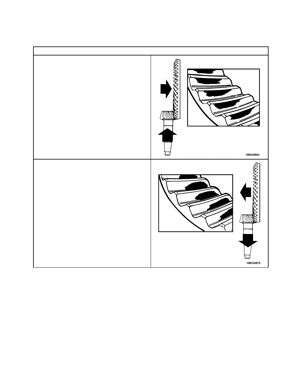
17. Check the pattern on the teeth of the ring gear.
Apply an indicator color (Prussian blue or yellow)
to the teeth. Use a pry bar between the ring gear
and the housing to prevent the ring gear from
turning freely. Turn the pinion shaft. Compare
the pattern on the ring gear teeth with the pat-
terns shown in Table 2. Adjust the gear clear-
ances as necessary. An adjustment of the pin-
ion to move the contact pattern also normally re-
quires an adjustment of the ring gear clearance
as described in Step 16.
18. Install the lockplates for the adjusting nuts.
Tighten the capscrews to 19 N•m (14 lbf ft). See
Figure 5.
13
Drive Axle, Speed Reducer, and Differential Repair
1400 SRM 285
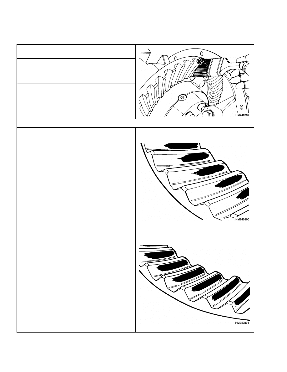
Table 2. Ring and Pinion Tooth Contact Adjustment
1.
Apply a colored dye or grease to approximately 12
of the ring gear teeth.
2.
Rotate ring gear forward and backward so that
the 12 gear teeth go past the drive six times to
get to the contact patterns. Repeat if needed to
get a clearer pattern.
3.
Check the tooth contact pattern on the ring gear.
Make sure that the pattern is checked on the side
of the tooth where the pinion applies the force.
Correct Tooth Contact
The contact area is the center between the top and
bottom of the tooth. The contact area is toward the
inner circumference of the ring gear.
NOTE:
Normal pattern during adjustment shown.
The contact area is the center between the top and
the bottom of the tooth. The contact area will be
almost the full length of the tooth.
NOTE:
Wear pattern from operation shown.
14
1400 SRM 285
Drive Axle, Speed Reducer, and Differential Repair
Table 2. Ring and Pinion Tooth Contact Adjustment (Continued)
Incorrect Tooth Contact
The pinion is too far away from the center of the
gear. Add shims to move pinion toward ring gear.
Check that the clearance is correct. Some movement
of ring gear away from pinion may be necessary.
The pinion is too close to the center of the ring gear.
Remove shims to move pinion away from the ring
gear. Check that the clearance is correct. Some
movement of the ring gear toward the pinion may
be necessary.
19. Adjust the thrust bolt after the final adjustment
of the ring and pinion.
Turn the thrust bolt
clockwise until it contacts the ring gear. Then
loosen the thrust bolt counterclockwise 1/6 of a
turn. Tighten the lock nut to 68 to 95 N•m (50
to 70 lbf ft).
20. Make sure that the special lock nut on the pinion
has been tightened to 340 N•m (250 lbf ft). Use a
punch with an 8 mm round tip to lock the special
nut on the end of the pinion shaft. Make sure
that the metal from the special nut contacts the
bottom of the slot in the pinion shaft.
21. Apply liquid sealant to the hub cap and install it
in the speed reducer housing at the end of the
pinion nut. Apply liquid sealant to the access
plate and install it on the speed reducer housing
over the speed reducer.
15
Drive Axle, Speed Reducer, and Differential Repair
1400 SRM 285
Drive Axle, Assemble
1.
If the axle spindles were removed from the differ-
ential housing, do this step. Install new O-rings
on the axle spindles. See Figure 17. Install the
axle spindle into the differential housing. Install
the eight M12 × 1.75 × 35 capscrews and lock-
washers that fasten each axle spindle to the dif-
ferential housing.
E/J1.25-1.75XL (E/J25-35XL) (C114):
Tighten
the capscrews to 66 N•m (48 lbf ft).
E/J2.00-3.00XL
(E/J40-60XL)
(B168,
C108):
Tighten the capscrews to 98 N•m (72 lbf ft).
E2.00-3.20XM (E45-65XM, E45-65XM
2
) (F108),
E2.00-3.20XM (E45-65Z) (G108), N30XMH and
N30XMH
2
(C210), V30ZMD (D210): Tighten the
capscrews to 90 N•m (66 lbf ft).
Figure 17. New O-Rings Installation
2.
Apply liquid sealant to the areas where the two
housings are joined. Install the differential as-
sembly and speed reducer housing into the dif-
ferential housing. The two M10 × 1.5 × 40 bolts
go into the top holes that fasten the housings to-
gether. Install the other six M10 × 1.5 × 30 bolts
to fasten the two housings together. Tighten the
bolts to 38 N•m (28 lbf ft).
3.
Assemble the brake assembly to the mount for
the axle housing as described in your vehicle’s
Brakes SRM.
4.
Lubricate the axle spindles with Never Seez
®
and
slide the mount brackets with the brake assem-
bly on the axle spindles.
NOTE:
The outer wheel bearing is lubricated by gear
oil from the differential housing. The inner wheel
bearing is lubricated by wheel bearing grease. Do
not use too much grease to lubricate the inner wheel
bearing so that grease is pushed past the seal into
the area for the brakes.
5.
Install a new oil seal in each hub. Install the oil
seal with the lip toward the outer bearing. Install
the inner bearing and seal as shown in Figure 1.
Put wheel bearing grease on the inner bearing.
6.
Install hub assembly on the axle housing. Be
careful that the seals are not damaged during
installation.
7.
Install the outer bearing cone on the axle hous-
ing.
Install the washer and lock plate.
See
Figure 18. Install the nut. Using the lock nut
wrench (Hyster Part Number 1304091), tighten
the nut to 205 N•m (151 lbf ft) while rotating the
hub. Loosen the nut until the hub turns freely.
The torque must be less than 27 N•m (20 lbf ft).
Tighten the nut to 34 N•m (25 lbf ft) or until the
first alignment position after 34 N•m (25 lbf ft).
Bend the lock plate over the nut.
Figure 18. Lock Plate Installation
8.
Put liquid sealant on the flange of the axle shaft.
Install the axle shafts.
E1.25-1.75XL (E/J25-35XL) (C114). Install the
four M8 × 1.25 × 16 capscrews and tighten them
to 20 N•m (15 lbf ft). See Figure 2 for the varia-
tion in the mounts for the drive wheels and axles.
When the capscrews are not used for the drive
wheel mounts, install the 10 M14 × 1.75 × 35 cap-
screws and tighten them to 155 N•m (115 lbf ft).
16

1400 SRM 285
Drive Axle, Speed Reducer, and Differential Repair
E2.00-3.00XL (E40-60XL) (C108).
Install the
eight M12 × 1.75 × 35 capscrews and tighten to
90 N•m (66 lbf ft).
J2.00-3.00XL (J40-60XL) (B168).
Install the
eight M12 × 1.75 × 35 capscrews and tighten to
98 N•m (72 lbf ft).
E2.00-3.20XM (E45-65XM, E45-65XM
2
) (F108),
E2.00-3.20XM (E45-65Z) (G108), N30XMH and
N30XMH
2
(C210), V30ZMD (D210). Install the
eight M12 × 1.75 × 35 capscrews and tighten to
90 N•m (66 lbf ft).
DRIVE AXLE ASSEMBLY, INSTALL
1.
Use a crane to move the drive axle assembly to
the floor in front of the lift truck. Slide the drive
axle assembly in position under the lift truck.
Turn the axle mounts forward so that there is
additional clearance for installation of the drive
axle.
2.
Align the bolt holes in the axle mounts and the
frame. The lower edge of the speed reducer hous-
ing must be raised over the frame crossmember
so that the drive axle assembly can be aligned
with the frame. Install the bolts to fasten the
mount brackets to the frame. See the following
NOTE.
NOTE: Some early models of the electric XL series
of SitDrives™ used M20 × 2.5 × 80 bolts to fasten
the mount brackets to the frame. If the lift truck has
these metric bolts, use the following torque values:
If the torque wrench is on the head of the bolt,
tighten the bolt to 540 N•m (400 lbf ft). If the
torque wrench is on the nut, tighten the nut to
473 N•m (350 lbf ft).
Later models of the electric XL series SitDrives™
use special 7/8 × 14 UNF bolts. This special set of
hardware has the following Hyster part numbers:
366714 (7/8 × 14 UNF bolt), 366713 (washer), and
366715 (hex nut). Other nuts and bolts must not
be used to replace these special bolts because of
the high torque values.
3.
Use a crane or jack to raise the drive axle from
the floor so that the drive wheels can be installed.
Install the drive wheels.
E1.25-1.75XL (E/J25-35XL) (C114). Tighten the
wheel nuts to 155 N•m (115 lbf ft).
E/J2.00-3.00XL
(E/J40-60XL)
(B168,
C108).
Tighten the wheel nuts to 237 to 305 N•m (175
to 225 lbf ft).
E2.00-3.20XM (E45-65XM, E45-65XM
2
) (F108),
E2.00-3.20XM (E45-65Z) (G108), N30XMH and
N30XMH
2
(C210), V30ZMD (D210). Tighten the
wheel nuts to 237 to 305 N•m (175 to 225 lbf ft).
4.
Put the drive wheels of the lift truck on blocks.
E/J1.25-1.75XL (E/J25-35XL) (C114). Install the
hand lever assembly for the parking brake. Care-
fully slide the hand lever assembly and cables
past the hydraulic lines and electric wires so that
the hand lever assembly can be fastened in posi-
tion on the cowl. Tighten the retainer that holds
the lines and cables near the floor plate. Install
the two M8 × 1.25 × 40 capscrews and washers
that hold the hand lever assembly to the cowl
mount.
DO NOT tighten the capscrews more
than 12 N•m (9 lbf ft) or you will bend the hand
lever assembly enough to cause it to malfunction.
E/J2.00-3.00XL
(E/J40-60XL)
(B168,
C108).
Connect the parking brake cables at the brakes.
E2.00-3.20XM (E45-65XM, E45-65XM
2
) (F108),
E2.00-3.20XM (E45-65Z) (G108), N30XMH and
N30XMH
2
(C210), V30ZMD (D210). Attach the
park brake assembly to the frame.
5.
Connect the brake lines to the wheel cylinders.
Make sure there is brake fluid in the reservoir.
Remove the air from the brake lines.
CAUTION
If brake fluid is permitted to flow freely over
the parts of the drive axle in this area, it can
cause problems in the lubrication in the mast
pivots and cause early failure of some grease
seals.
6.
Make sure that a small hose is installed from the
special fitting to a container for brake fluid when
air is removed from the brake lines.
7.
Adjust the clearance of the brake shoes as de-
scribed in your vehicle’s Brakes SRM.
8.
Install the traction motor.
See your vehicle’s
Frame SRM for procedures to install the trac-
tion motor.
17

Torque Specifications
1400 SRM 285
9.
Install and tighten the drain plug. Fill the differ-
ential housing with Ultra Gear Lubrication Gear
Oil
®
SAE 80W (Chevron) through the fill hole un-
til the oil level is even with the bottom of the fill
hole. Install the plug.
10. Install the mast as described in your vehicle’s
Mast SRM. Install the battery as described in
your vehicle’s Periodic Maintenance SRM. Re-
move the blocks so that the lift truck is on its
wheels.
Torque Specifications
WHEEL NUTS
E/J1.25-1.75XL (E/J25-35XL) (C114)
155 N•m (115 lbf ft)
E/J2.00-3.00XL (E/J40-60XL) (B168, C108)
237 to 305 N•m (175 to 225 lbf ft)
E2.00-3.20XM (E45-65XM, E45-65XM
2
) (F108),
E2.00-3.20XM (E45-65Z) (G108), N30XMH and
N30XMH
2
(C210), V30ZMD (D210)
237 to 305 N•m (175 to 225 lbf ft)
AXLE SHAFT CAPSCREWS
E/J1.25-1.75XL (E/J25-35XL) (C114)
M8 x 1.25 x 16 capscrews (4) 20 N•m (15 lbf ft)
M14 x 1.75 x 35 capscrews (10) 155 N•m (115 lbf ft)
E2.00-3.00XL (E40-60XL) (C108)
90 N•m (66 lbf ft)
J2.00-3.00XL (J40-60XL) (B168)
98 N•m (72 lbf ft)
E2.00-3.20XM (E45-65XM, E45-65XM
2
) (F108),
E2.00-3.20XM (E45-65Z) (G108), N30XMH and
N30XMH
2
(C210), V30ZMD (D210)
90 N•m (66 lbf ft)
AXLE HANGERS TO FRAME
M20 × 2.5 × 80 bolts (early models)
Torque wrench on head of bolt 540 N•m (400 lbf ft)
Torque wrench on nut of bolt 473 N•m (350 lbf ft)
7/8 × 14 UNF bolts (later models)
Torque wrench on head of bolt 745 to
780 N•m (550 to 575 lbf ft)
Torque wrench on nut of bolt 680 to 715 N•m
(500 to 525 lbf ft)
BACK PLATE TO AXLE MOUNT
CAPSCREWS
E/J1.25-1.75XL (E/J25-35XL) (C114)
(10 capscrews)
122 N•m (90 lbf ft)
E/J2.00-3.00XL (E/J40-60XL) (B168, C108)
Top 3 (6) 110 N•m (81 lbf ft)
Bottom 4 (8) 245 N•m (180 lbf ft)
E2.00-3.20XM (E45-65XM, E45-65XM
2
) (F108),
E2.00-3.20XM (E45-65Z) (G108), N30XMH and
N30XMH
2
(C210), V30ZMD (D210)
255 N•m (188 lbf ft)
WHEEL CYLINDER CAPSCREWS
E/J1.25-1.75XL (E/J25-35XL) (C114)
(8 capscrews)
10 to 14 N•m (7 to 10 lbf ft)
E/J2.00-3.00XL (E/J40-60XL) (B168, C108)
Top 2 (4) 78 to 85 N•m (58 to 66 lbf ft)
Bottom 2 (4) 80 to 102 N•m (67 to 75 lbf ft)
E2.00-3.20XM (E45-65XM, E45-65XM
2
) (F108),
E2.00-3.20XM (E45-65Z) (G108), N30XMH and
N30XMH
2
(C210), V30ZMD (D210)
13 to 20 N•m (10 to 15 lbf ft)
RING GEAR TO DIFFERENTIAL CASE
7/16 UNF × 1 bolts (12)
111 N•m (82 lbf ft)
DIFFERENTIAL CASE HALVES
3/8 UNF × 3-1/2 capscrews (8)
50 N•m (37 lbf ft)
BEARING CAP CAPSCREWS
Bearing cap capscrews for differen-
tial bearings (4)
95 to 110 N•m (70 to 80 lbf ft)
18

1400 SRM 285
Troubleshooting
RETAINER CAPSCREWS
Retainer capscrews for adjusting nuts (2)
19 N•m (14 lbf ft)
AXLE HOUSING TO DIFFERENTIAL
HOUSING
E/J1.25-1.75XL (E/J25-35XL) (C114)
M12 x 1.75 x 35 capscrews (16) 66 N•m (48 lbf ft)
E/J2.00-3.00XL (E/J40-60XL) (B168, C108)
M12 x 1.75 x 35 capscrews (16) 98 N•m (72 lbf ft)
E2.00-3.20XM (E45-65XM, E45-65XM
2
) (F108),
E2.00-3.20XM (E45-65Z) (G108), N30XMH and
N30XMH
2
(C210), V30ZMD (D210)
90 N•m (66 lbf ft)
PINION NUT
Pinion Nut
340 N•m (250 lbf ft)
SPEED REDUCER HOUSING TO
DIFFERENTIAL HOUSING
M10 × 1.5 × 30 bolts (6)
38 N•m (28 lbf ft)
M10 × 1.5 × 40 bolts (2)
38 N•m (28 lbf ft)
TRACTION MOTOR TO TRANSMISSION
M10 × 1.5 × 40 bolts (7)
38 N•m (28 lbf ft)
Troubleshooting
PROBLEM
POSSIBLE CAUSE
PROCEDURE OR ACTION
The lift truck will not move.
An axle shaft is broken.
Install new axle shaft.
The differential is damaged.
Repair differential.
The drive axle has leaks.
The drain or fill plug has damaged
threads, is loose, or is missing.
Repair threads. Tighten plug. Install
missing part.
The O-rings or seals have damage.
Install new O-rings and seals.
The drive axle housing is cracked.
Install new drive axle housing.
The drive axle makes noise.
The bearings have damage.
Install new parts.
The brake assembly is damaged.
Repair brake assembly.
The oil level is low.
Fill as required. Check for leaks.
The axle mounting capscrews are
loose.
Tighten
capscrews
to
specified
torque.
19

NOTES
____________________________________________________________
____________________________________________________________
____________________________________________________________
____________________________________________________________
____________________________________________________________
____________________________________________________________
____________________________________________________________
____________________________________________________________
____________________________________________________________
____________________________________________________________
____________________________________________________________
____________________________________________________________
____________________________________________________________
____________________________________________________________
____________________________________________________________
____________________________________________________________
____________________________________________________________
____________________________________________________________
____________________________________________________________
____________________________________________________________
20


TECHNICAL PUBLICATIONS
1400 SRM 285
5/04 (11/03)(7/99)(7/94)(10/85)(585) Printed in United Kingdom
Document Outline
- toc
- Drive Axle, Speed Reducer, and Differential
- Safety Precautions Maintenance and Repair
- General
- Description
- Drive Axle, Speed Reducer, and Differential Repair
- Torque Specifications
- Wheel Nuts
- Axle Shaft Capscrews
- Axle Hangers to Frame
- Back Plate to Axle Mount Capscrews
- Wheel Cylinder Capscrews
- Ring Gear to Differential Case
- Differential Case Halves
- Bearing Cap Capscrews
- Retainer Capscrews
- Axle Housing to Differential Housing
- Pinion Nut
- Speed Reducer Housing to Differential Housing
- Traction Motor to Transmission
- Troubleshooting
- tables
Wyszukiwarka
Podobne podstrony:
897506 4000SRM0521 (05 2004) UK EN
897480 1400SRM0499 (10 2004) UK EN
910460 1600SRM0258 (05 2004) UK EN
910030 1400SRM0047 (08 2004) UK EN
1467764 8000SRM0738 (05 2004) UK EN
897390 0100SRM0449 (05 2004) UK EN
1553986 8000SRM1083 (05 2004) UK EN
897880 1400SRM0618 (06 2004) UK EN
897985 1400SRM0657 (05 1997) UK EN
897104 0100SRM0322 (05 2004) UK EN
897506 4000SRM0521 (05 2004) UK EN
897480 1400SRM0499 (10 2004) UK EN
więcej podobnych podstron