2009 Eaton Corporation. All rights reserved.
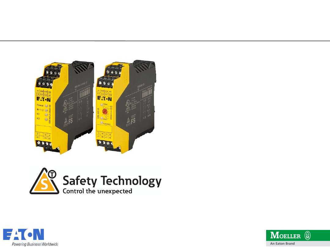
Safety Products
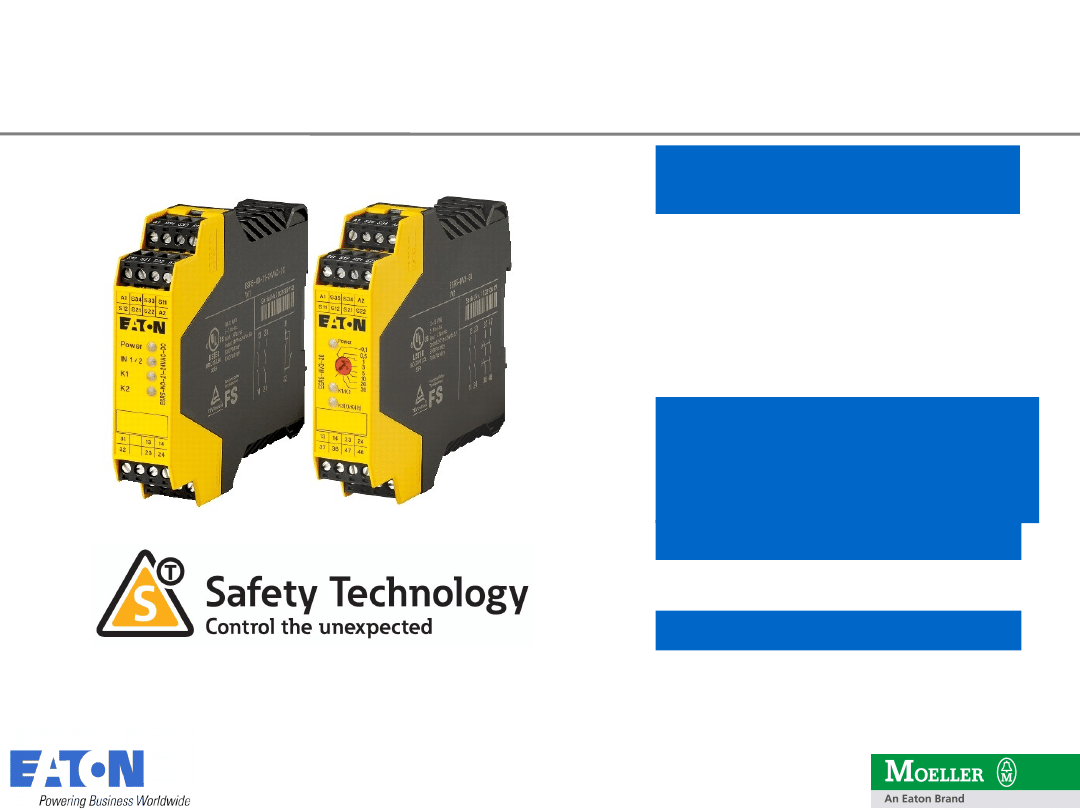
ESR5 & easySafety
Logic units for safety functions
2
2
09.06.2010
2009 Eaton Corporation. All rights reserved.
Safety Technology
Content
Content
The ESR Safety Relay-Program
- Program Overview
- Product Features and Benefits
- Possible Applications and Examples
- Competitors
The safety control relay „easySafety“
-
Product Portfolio
-
Changes in Standards
-
Product Features and Benefits
-
Example
-
Competitors
-
Accessories
-
Order Information
3
3
09.06.2010
2009 Eaton Corporation. All rights reserved.
ESR5 Safety Relays
Two-hand control
Emergency Stop, Safety
Gate
Emergency Stop, Safety
Gate,
Stop Category 1, Light
Curtain
ESR5-NO-21-24VAC-DC
ESR5-NO-31-24VAC-DC
ESR5-NO-31-230VAC
ESR5-NO-31-AC-DC*
ESR5-NO-41-24VAC-DC
ESR5-NV3-30
ESR5-NZ-21-24VAC-DC
Contact Expansion
ESR5-NE-51-24VAC-DC
ESR5-VE3-42
* New type designation, substitute for ESR5-NO-31-24V-
230VAC-DC

4
4
09.06.2010
2009 Eaton Corporation. All rights reserved.
• One device per function.
For each function an optimal
solution
• COMBICON coded connectors
Convenient connectivity
Accurate indicator of the
voltage supply, input
circuits and relays
Rapid diagnosis
Compact body just 22.5 mm
width saves panel space
Slim design
• Positively actuated
contacts (acc. to EN
50205)
• Redundant design
Proven
Safety Technology
ESR5 Safety Relays
5
5
09.06.2010
2009 Eaton Corporation. All rights reserved.
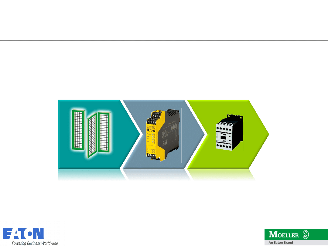
Safety Functions
Safety related parts of a control system
Sensor / Control
Receive signals,
recognize danger
Actuator / switch
element
Stop movement,
Eliminate risk
Control
Signal analysis,
Monitoring of
sensors and
actuators
6
6
09.06.2010
2009 Eaton Corporation. All rights reserved.
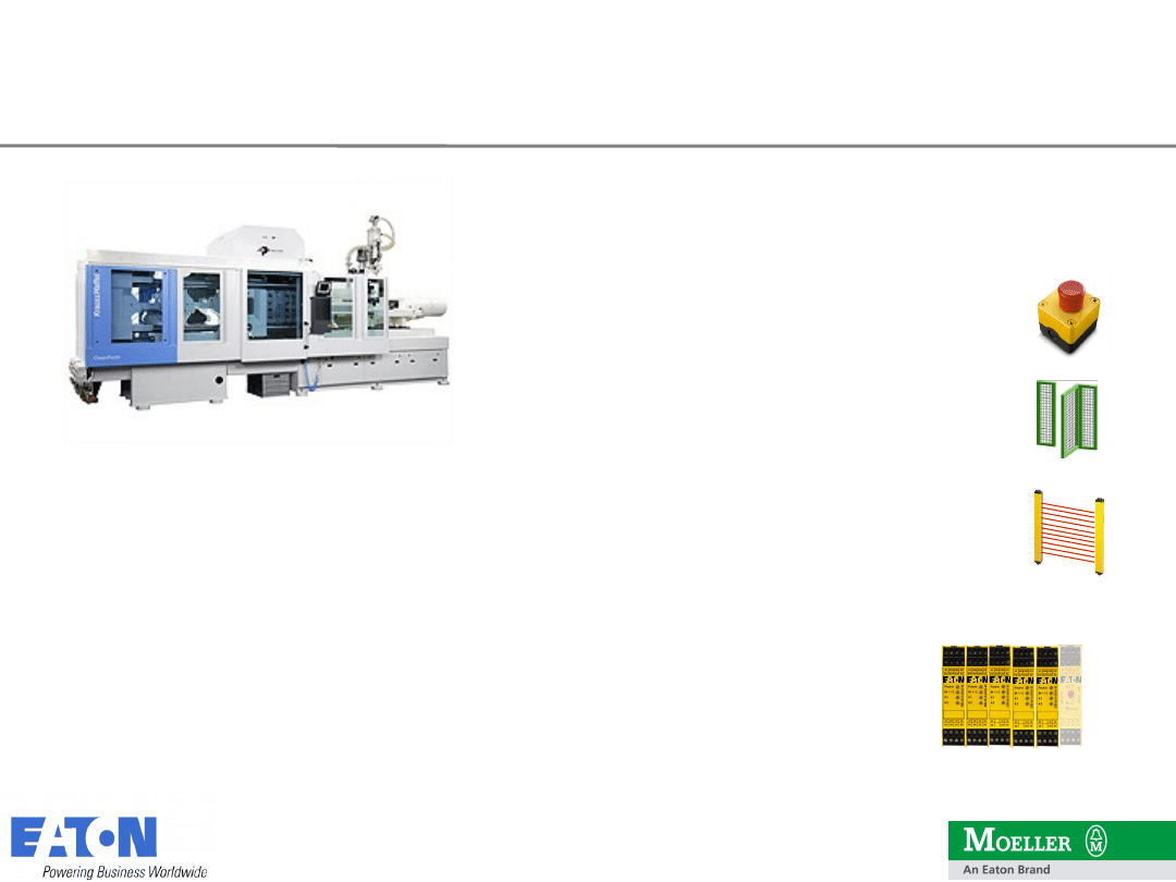
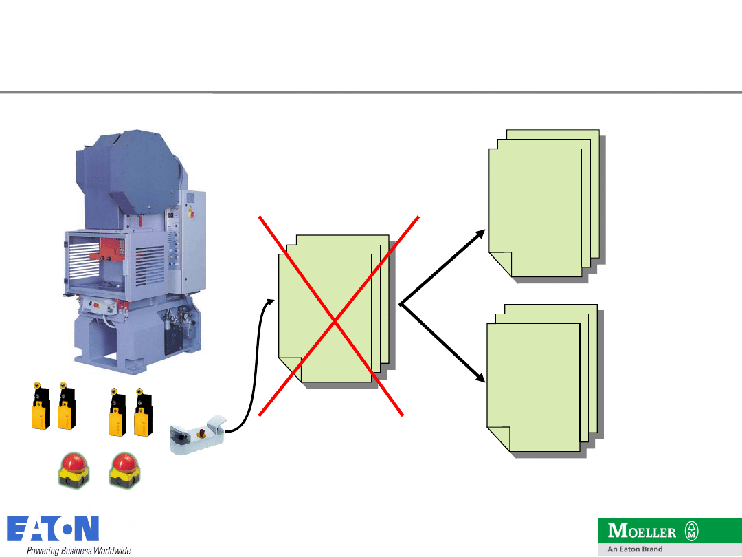
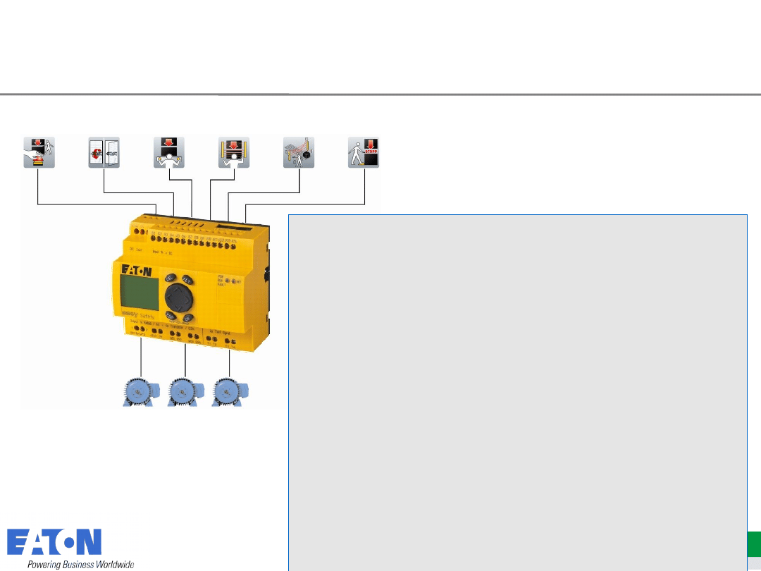
Application example: Injection
Machine Safety Function:
2 Emergency Stop
3 Safety Gates
1 Light Curtain (optional)
Safety Relays = max. 6 modules
Max. Width 135 mm
7
7
09.06.2010
2009 Eaton Corporation. All rights reserved.
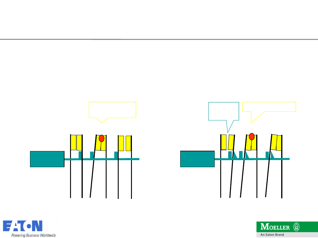
•
In a safety relay with integrated monitoring the status of positively
actuated contacts is used for error detection.
•
Thus, dangerous errors, like the welding of contacts, certainly recognized
and achieved a high safety level
standard
relay
positively actuated
contacts
Coil
N/C
N/
O
Coil
Min.
0,5 mm
welded contact
NO
welded
contact
Positively actuated contacts

8
8
09.06.2010
2009 Eaton Corporation. All rights reserved.
Positively actuated contacts
acc. to
EN 50205
Functional Safety
EN 954
Category 4
EN ISO 13849 PL e
EN 62061
SIL
CL3
IEC 61508
SIL 3
Performance Safety standards
9
9
09.06.2010
2009 Eaton Corporation. All rights reserved.
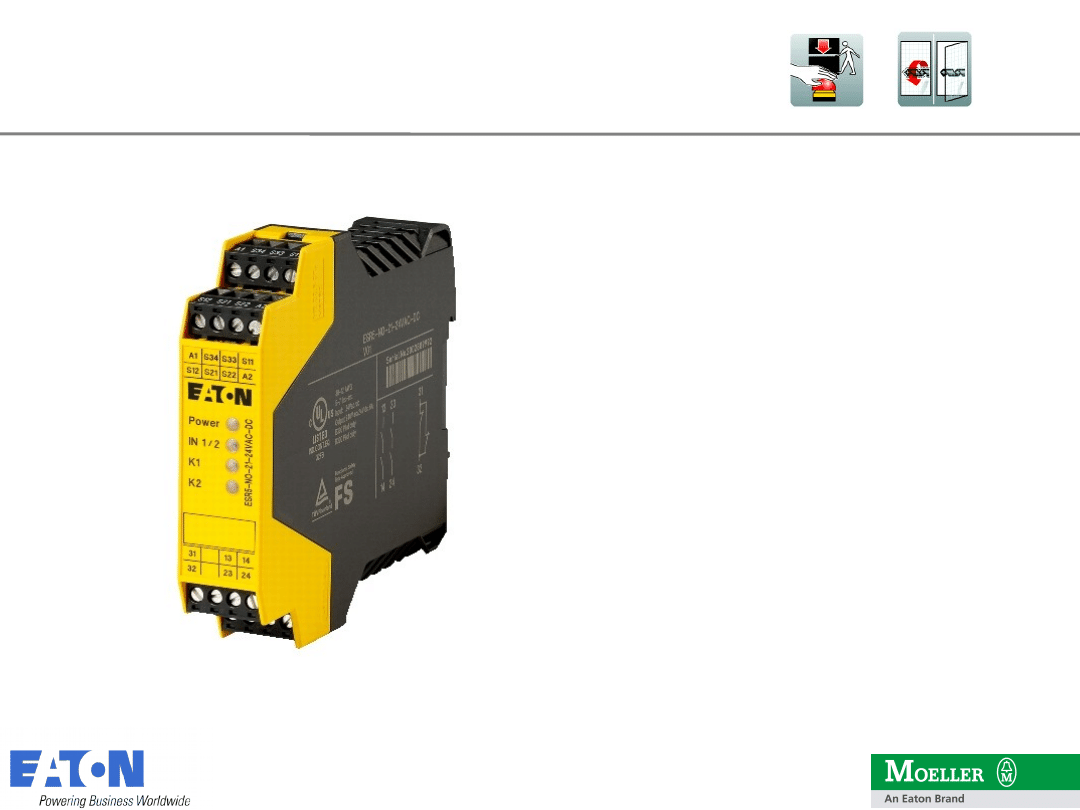
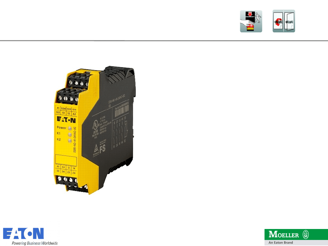
•
base device for emergency stop and
safety gate applications
•
one- or two-channel activation
•
cross circuiting monitoring
•
2 enabling rungs
•
1 signalling rung
•
supply voltage: 24 V AC/DC
•
manual / automatic aktivation
Functional Safety
•
Category 4 (EN 954–1)
•
EN ISO 13849-1 Performance Level PL
e
•
SILCL 3 (IEC 62061)
Safety relay ESR5
Model ESR5-NO-21-24VAC-DC
1
0
10
09.06.2010
2009 Eaton Corporation. All rights reserved.
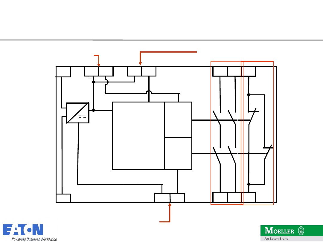
14 24 32
A1
A2
~ +
-
S11
S12
LOGIC
K1
K2
13 23 31
S34
S33
S22
S21
24 VDC +
0 VDC -
sensor
circuit 1
Sensor
circuit 2
Reset circuit
(Please note IL !)
Enabling rungs
Signallin
g rung
Construction of Safety Relay
1
1
11
09.06.2010
2009 Eaton Corporation. All rights reserved.
•
base device for emergency stop and
safety gate applications
•
one channel activation
•
4 enabling rungs
•
1 signalling rung
•
supply voltage: 24 V AC/DC
•
manual / automatic activation
Functional Safety
•
Category 2 (EN 954–1)
•
EN ISO 13849-1 Performance Level PL
d
•
SILCL 3 (IEC 62061)
Safety relay ESR5
Model ESR5-NO-41-24VAC-DC
1
2
12
09.06.2010
2009 Eaton Corporation. All rights reserved.
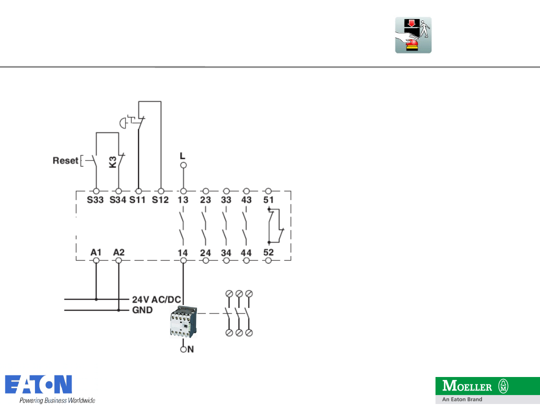
Relay activated when:
•
24 VDC / 0 VDC on A1,
A2
•
Emergency Stop switch
unlocked
•
Reset button pressed
Relais deactivated
when:
•
Emergency Stop button
pressed
•
Emergency Stop circuit
open
ESR5-NO-41
Application Examples
1
3
13
09.06.2010
2009 Eaton Corporation. All rights reserved.
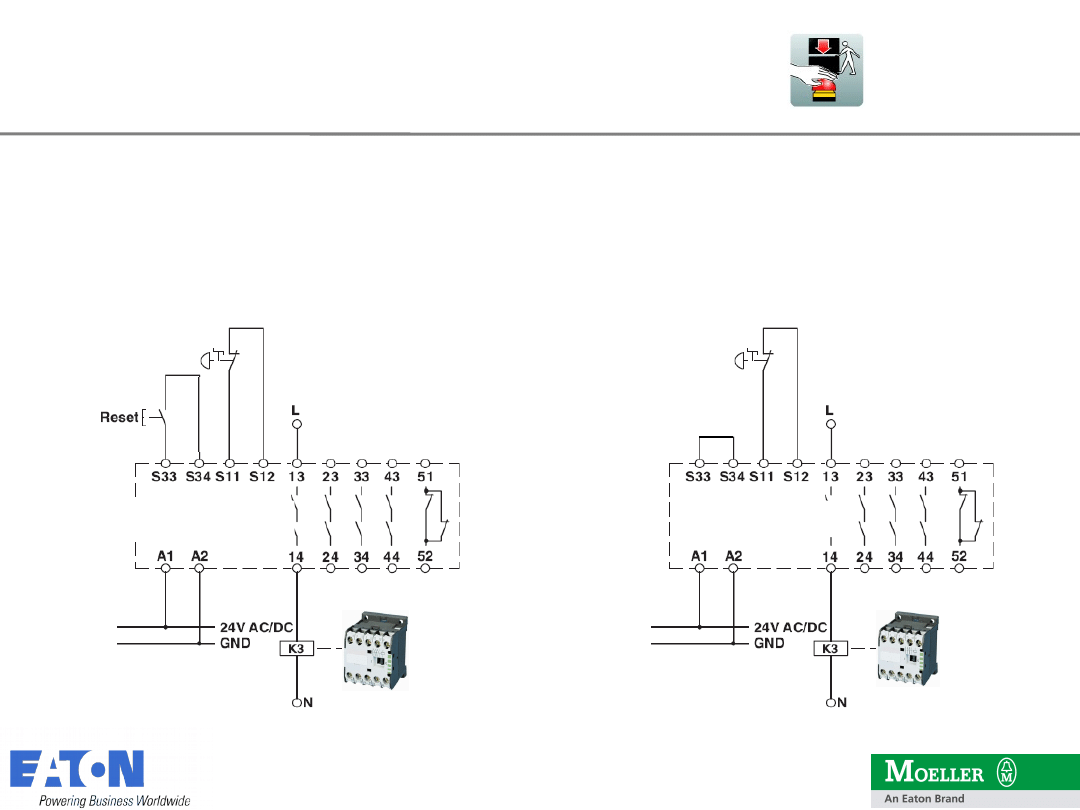
Manual Reset
(without external device monitoring EDM)
ESR5-NO-41
ESR5-NO-41
Automatic Reset
(without EDM)
Application Examples
1
4
14
09.06.2010
2009 Eaton Corporation. All rights reserved.
•
base device for emergency stop and
safety gate applications
•
one- or two-channel activation
•
cross circuiting monitoring
•
3 enabling rungs
•
1 signalling rung
•
supply voltage: 24 V AC/DC
•
manual / automatic activation
Functional Safety
•
Category 4 (EN 954–1)
•
EN ISO 13849-1 Performance Level PL
e
•
SILCL 3 (IEC 62061)
Safety Relay ESR5
Model ESR5-NO-31-24VAC-DC

1
5
15
09.06.2010
2009 Eaton Corporation. All rights reserved.
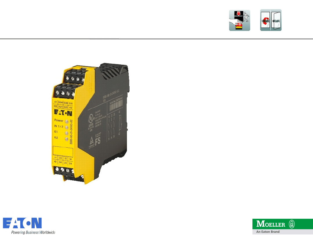
•
base device for emergency stop and
safety gate applications
•
one- or two-channel activation
•
cross circuiting monitoring
•
3 enabling rungs
•
1 signalling rung
•
supply voltage:
•
24-230 V AC/DC
•
230 V AC/DC
•
manual / automatic activation
Funktionale Sicherheit
•
Category 4 (EN 954–1)
•
EN ISO 13849-1 Performance Level PL e
•
SILCL 3 (IEC 62061)
Safety Relay ESR5
Model ESR5-NO-31-AC-DC /-230VAC
New type designation ESR5-NO-31-AC-DC replaces
previous ESR5-NO-31-24V-230VAC-DC
1
6
16
09.06.2010
2009 Eaton Corporation. All rights reserved.
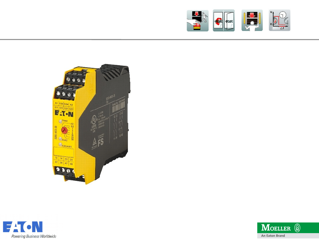
•
base device for emergency stop, safety
gate and light curtain applications
•
For controlled shutdown according to Stop
Category 1
•
one- or two-channel activation
•
cross circuiting monitoring
•
4 enabling rungs
•
2 undelayed
•
2 delayed
•
supply voltage: 24 V AC/DC
•
manual / automatic aktivation
Functional Safety
•
Category 4 (EN 954–1)
•
EN ISO 13849-1 Performance Level PL e
•
SILCL 3 (IEC 62061)
Safety Relay ESR5
Model ESR5-NV-3-30
1
7
17
09.06.2010
2009 Eaton Corporation. All rights reserved.
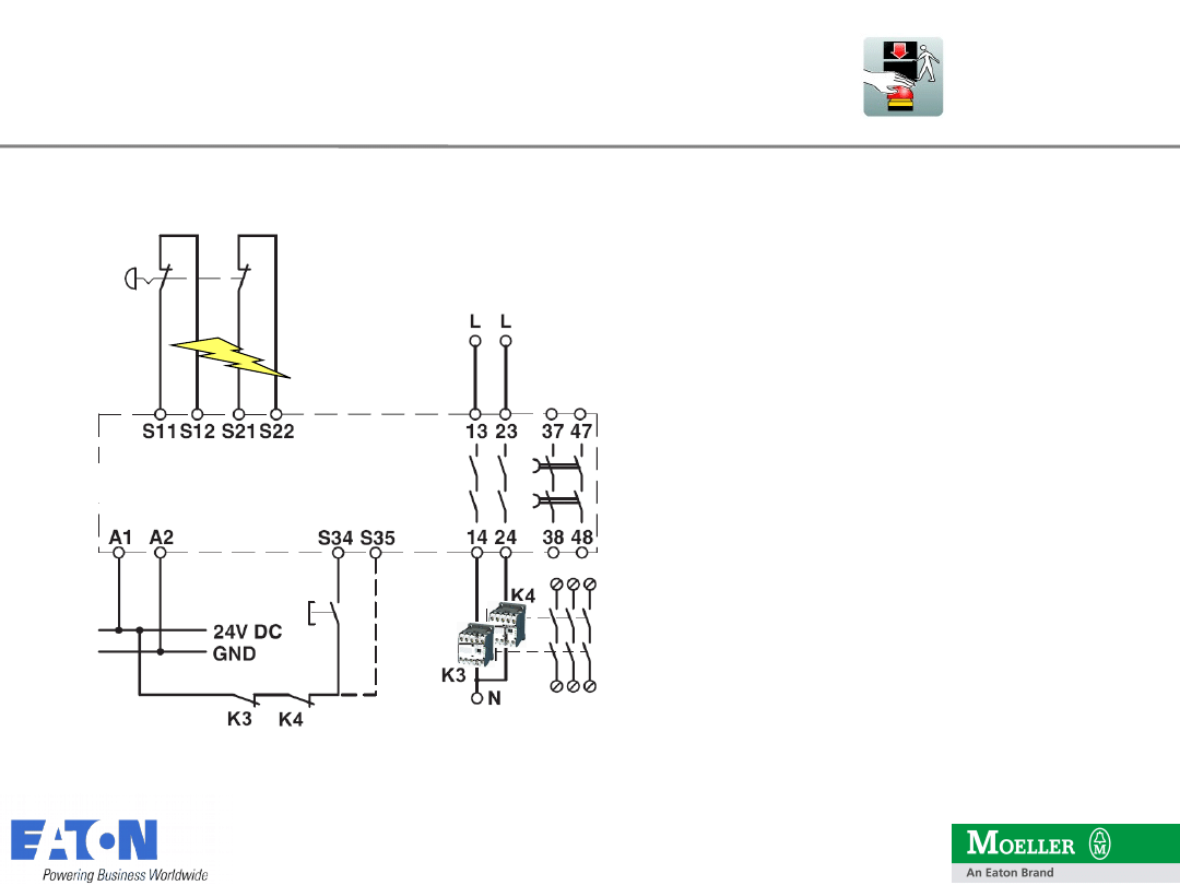
Relay activated when
•
24 VDC / 0 VDC on A1, A2
•
Emergency Stop switch
unlocked
•
Reset button pressed
Relais deactivated when
•
Emergency Stop button
pressed
•
Short circuit in
emergency stop lines
•
Emergency Stop circuit
open
24 VDC
0 VDC
cross circuit
monitoring
ESR5-NV-3-30
Application Examples

1
8
18
09.06.2010
2009 Eaton Corporation. All rights reserved.
•
base device for Two-hand- and Safety
Gate applications
•
Acc. to EN 574 Type III C, IEC 60204-1
•
Two channel activation
•
With simultaneity monitoring
< 0,5 sec.
•
2 enable rungs
•
1 signalling rung
•
Supply voltage: 24 V AC/DC
Functional Safety
•
Category 4 (EN 954–1)
•
EN ISO 13849-1 Performance Level PL e
•
SILCL 3 (IEC 62061)
Safety Relay ESR5
Model ESR5-NZ-21-24VAC-DC
1
9
19
09.06.2010
2009 Eaton Corporation. All rights reserved.
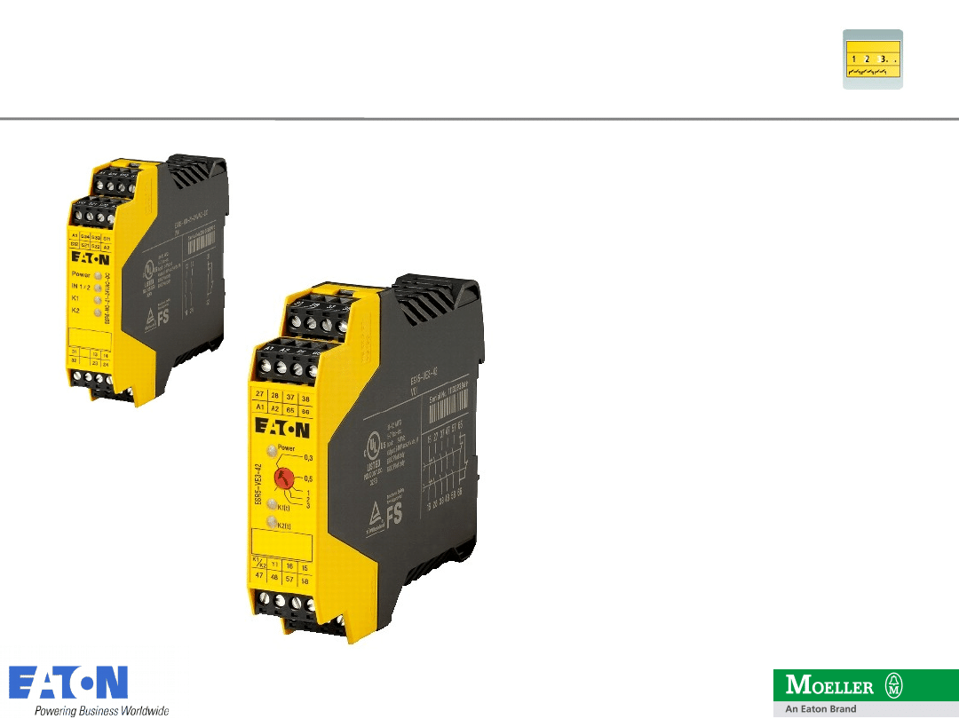
•
Expansion module for Emergency
Stop and Safety Gate applications
•
One or two-channel activation
•
4 enable rungs (delayed)
•
2 signalling rungs
•
Supply voltage: 24 V DC
Functional Safety
•
Categorie 3 (EN 954–1)
•
EN ISO 13849-1 Performance Level PL
d
•
SILCL 2 (IEC 62061)
Safety Relay ESR5
Model ESR5-VE3-42 Contact Expansion
2
0
20
09.06.2010
2009 Eaton Corporation. All rights reserved.
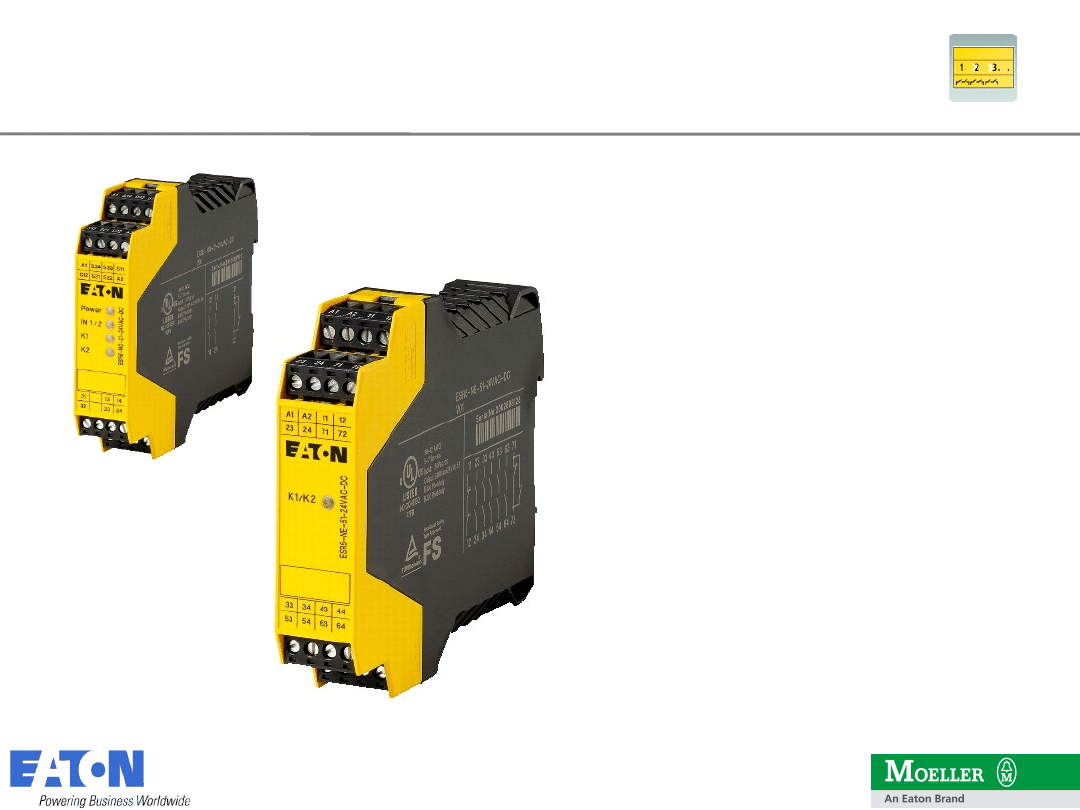
•
Expansion module for Emergency
Stop and Safety Gate applications
•
One or two-channel activation
•
5 enable rungs (undelayed)
•
2 signalling rungs
•
Supply Voltage: 24 V DC
Functional Safety:
•
Category 4 (EN 954–1)
•
EN ISO 13849-1 Performance Level PL
e
•
SILCL 3 (IEC 62061)
Safety Relay ESR5
Model ESR5-NE-51-24VAC-DC Contact Expansion
2
1
21
09.06.2010
2009 Eaton Corporation. All rights reserved.
Brochure „Safety Logic for machines und
systems“ (BR05107001Z-EN,
Art.-Nr. 150689)
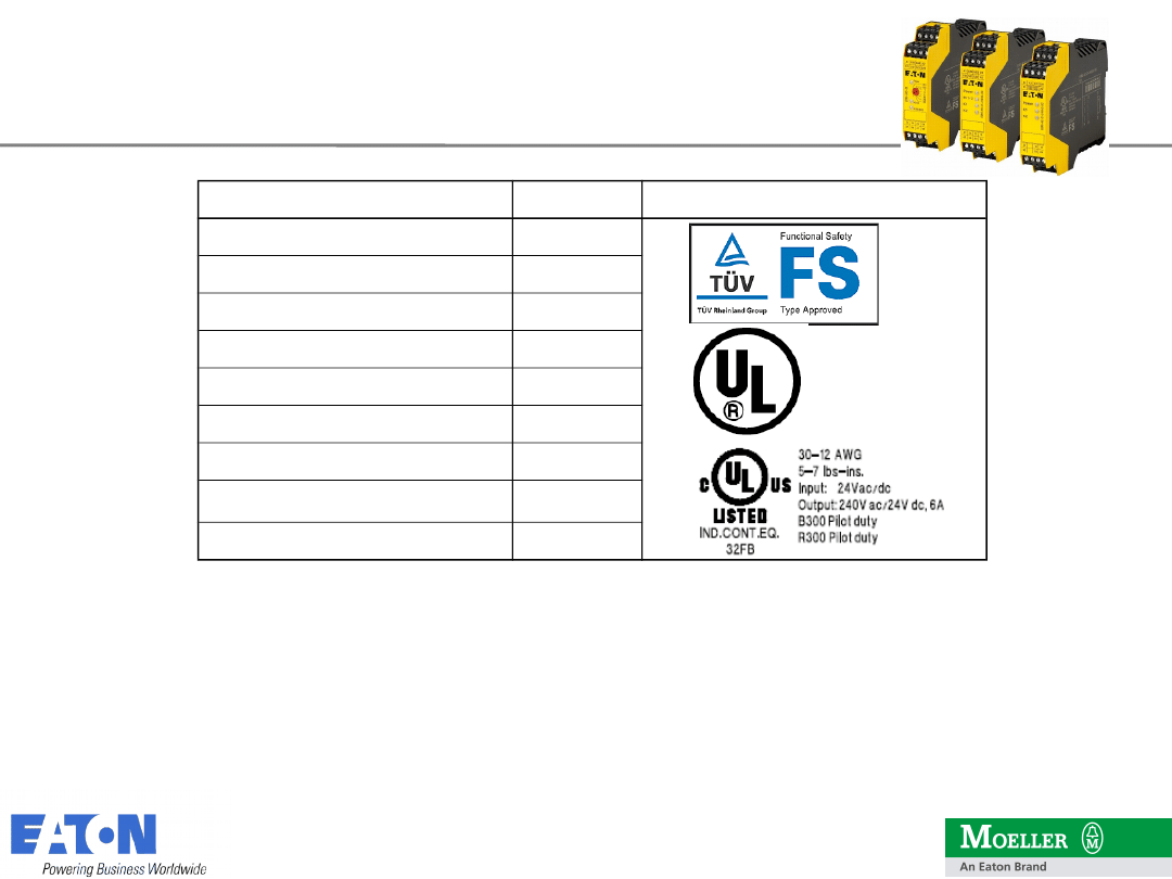
ESR5 Instruction Leaflet IL (AWA)
Type
Art. - Nr.
Approvals
ESR5-NO-21-24VAC-DC
118700
ESR5-NO-31-24VAC-DC
118702
ESR5-NO-31-230VAC
119380
ESR5-NO-31-AC-DC
118704
ESR5-NO-41-24VAC-DC
118701
ESR5-NZ-21-24VAC-DC
118703
ESR5-NV3-30
118705
ESR5-NE-51-24VAC-DC
118707
ESR5-VE3-42
118706
Safety Relay ESR5
Order Informationen
2
2
22
09.06.2010
2009 Eaton Corporation. All rights reserved.
Safety Relays ESR5
Competitors
•
PILZ
•
Schneider
•
Siemens
•
Schmersal
•
Rockwell OMRON
•
ABB / Jokab Safety
•
Wieland
•
Dold
2
3
23
09.06.2010
2009 Eaton Corporation. All rights reserved.
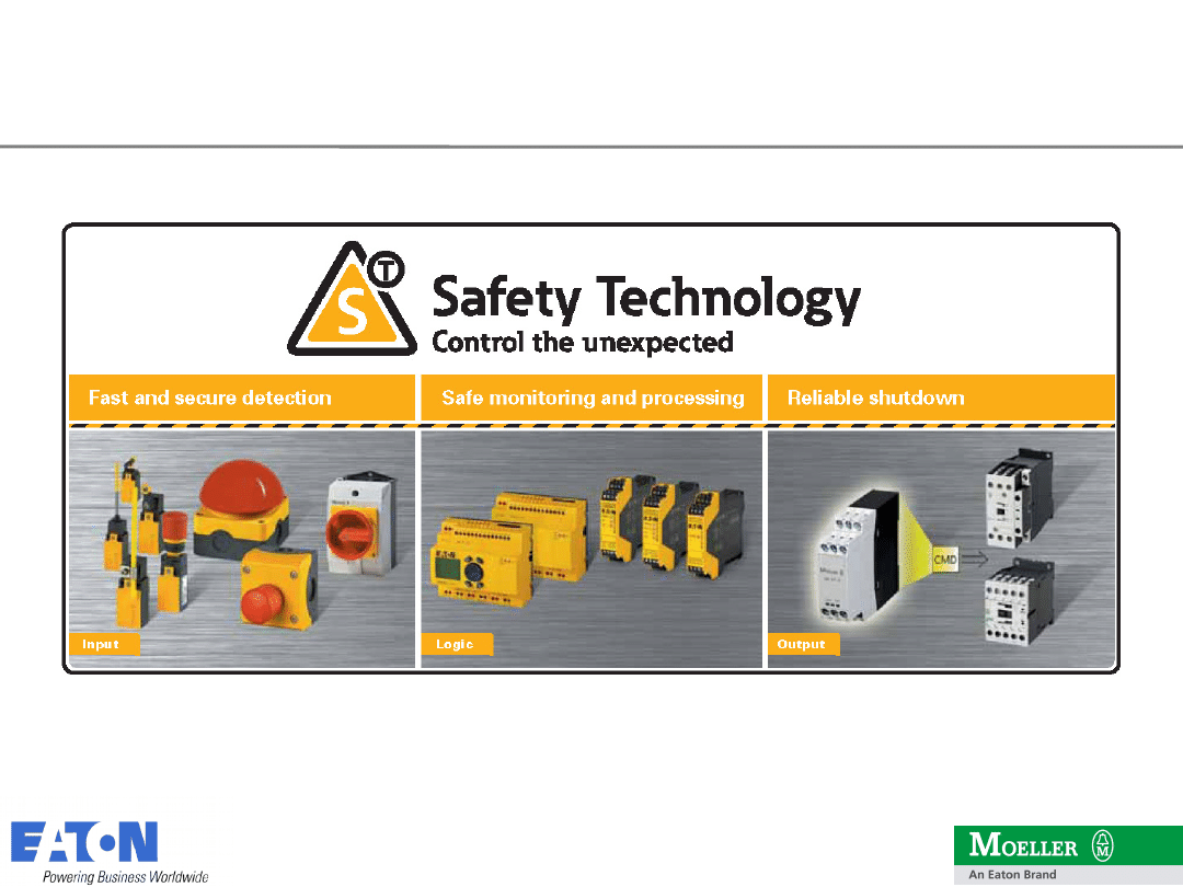
Safety Technology
Content
Content
The ESR Safety Relay-Program
- Program Overview
- Product Features and Benefits
- Possible Applications and Examples
- Competitors
The safety control relay „easySafety“
-
Product Portfolio
-
Changes in Standards
-
Product Features and Benefits
-
Example
-
Competitors
-
Accessories
-
Order Information
2
4
24
09.06.2010
2009 Eaton Corporation. All rights reserved.
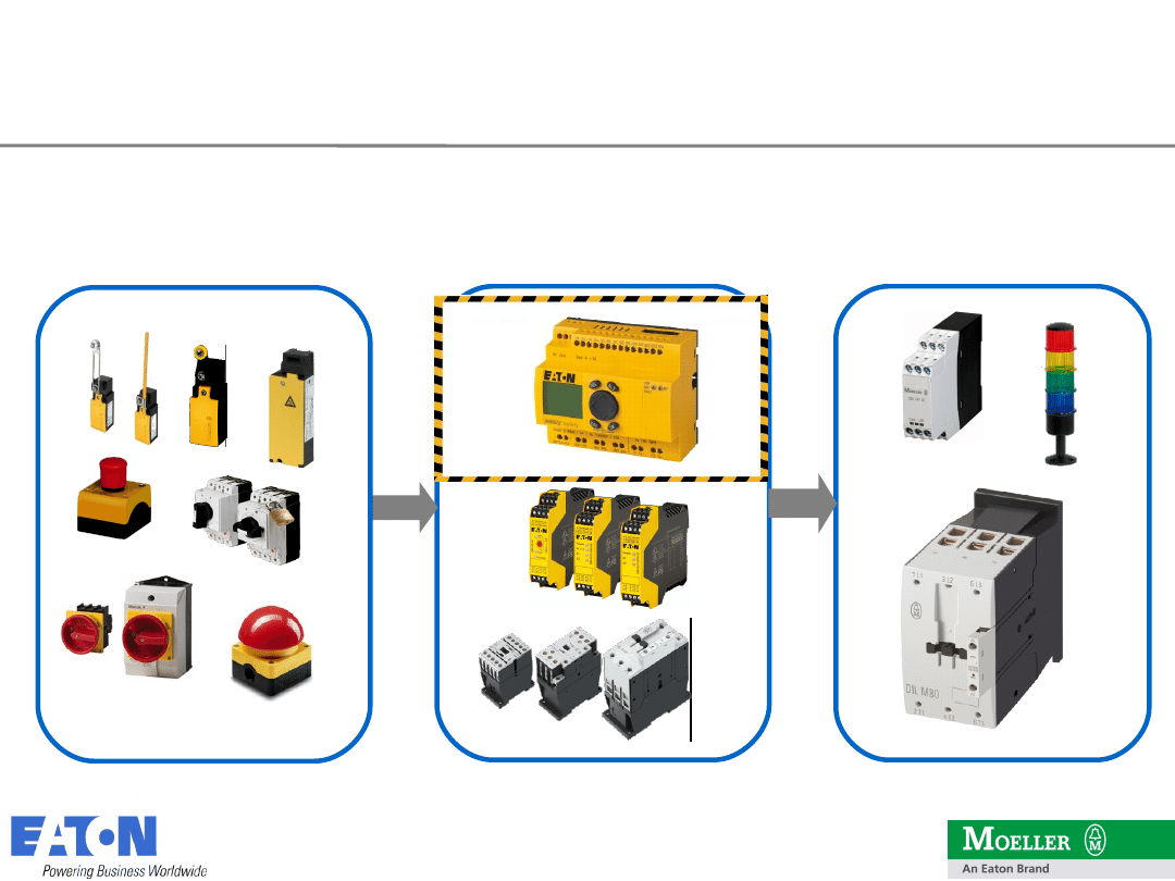
Input
Logic
Output
Safety engineering
Product portfolio
2
6
26
09.06.2010
2009 Eaton Corporation. All rights reserved.
EN 954-1
Categories
B-4
ISO 13849-1
Performance
Level a-e
IEC 62061
SIL 1-3
EN valid
since 2006
EN valid after
February 2007
transitional period
until the
end of 2011
easySafety
Safety technology – Changes in standards
2
7
27
09.06.2010
2009 Eaton Corporation. All rights reserved.
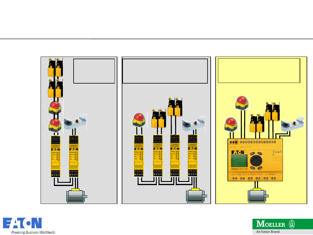
Solution with easySafety
ISO 13849-1 PL d/e
EN 62061 SIL 2/3
In the past:
EN 954-1
category 3
Today: Solution with ESR5
ISO 13849-1 PL d/e
EN 62061 SIL 2/3
easySafety
Changed standards affect sensor
diagnostics

2
8
28
09.06.2010
2009 Eaton Corporation. All rights reserved.
Solution with easySafety:
Reduced wiring
Timing element for Stop Category 1 according
to EN 60204-1 (Off-delay) built-in
On-board display for plain text diagnostics
messages
Logic operations can be implemented through
easy circuit diagram technology!
Simple solutions to special functions such as
Setup mode
easySafety
Advantages of easySafety
2
9
29
09.06.2010
2009 Eaton Corporation. All rights reserved.
Safety functions with
ESR5 and easySafety
3
0
30
09.06.2010
2009 Eaton Corporation. All rights reserved.
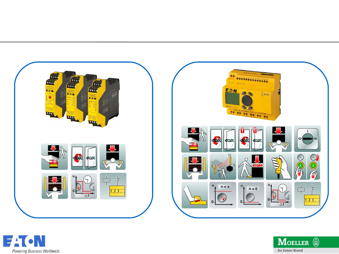
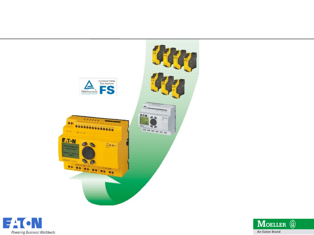
Safety functions
easySafety – All in One
Standard
functions
easySafety
All in One
3
3
33
09.06.2010
2009 Eaton Corporation. All rights reserved.
easySafety
Features / Benefits and USP‘s
Combinable
:
Standard and safety functions in one
device;
separate safety and standard circuit
diagram
Tamper protection for the OEM
Know-how
protection for engineer
flexibility for the operator
Compact
:
A multitude of safety relays in a single
device
Cuts stock-keeping costs
On-board
:
Direct diagnostics and comprehensive
protection measures through built-
in display
High machine availability
Advance-tested
: Offline simulation of safety application
Clear time savings in installation and commissioning
3
7
37
09.06.2010
2009 Eaton Corporation. All rights reserved.
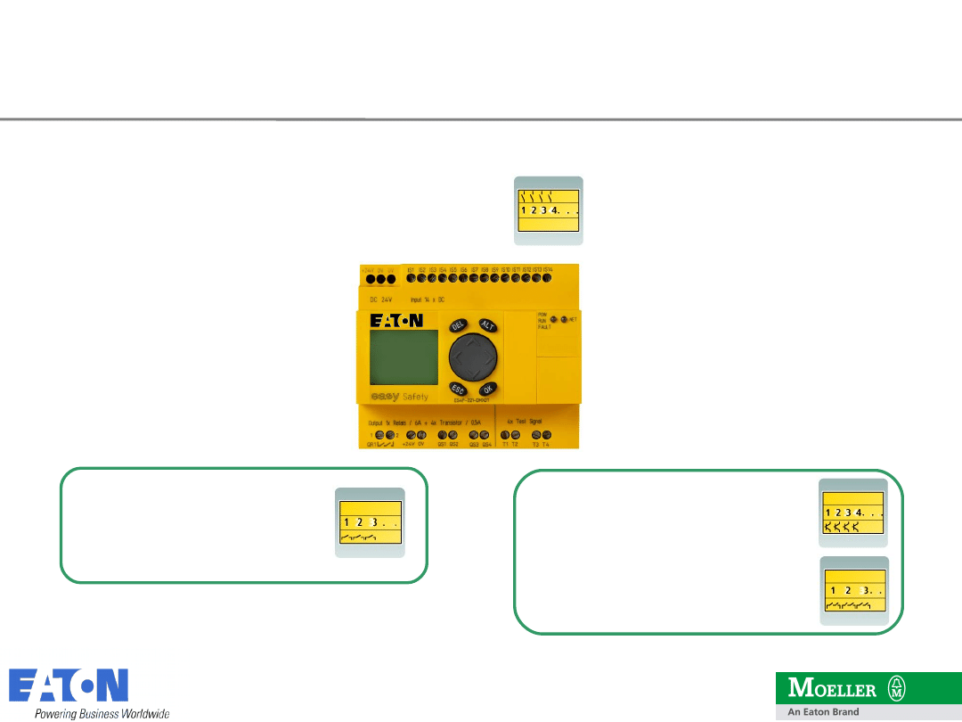
14 inputs (IS)
4 transistors (QS)
1 redundant relay (QR)
4 simple relays (QS)
or
easySafety
Safety Inputs and Outputs
3
8
38
09.06.2010
2009 Eaton Corporation. All rights reserved.
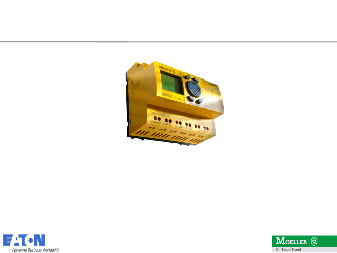
The rugged
choice:
The versatile
choice:
ES4P-221-DRXX1
ES4P-221-DMXX1
ES4P-221-DRXD1
ES4P-221-DMXD1
easySafety
Always the right model!

3
9
39
09.06.2010
2009 Eaton Corporation. All rights reserved.
easySafety
Built-in interfaces easyNet and easyLink
Safety *
application
Safety *
application
Standard
application
Standard
application
easyNet (standard)
also easy800,
MFD, EC4P
easyLink
easyLink
4
0
40
09.06.2010
2009 Eaton Corporation. All rights reserved.
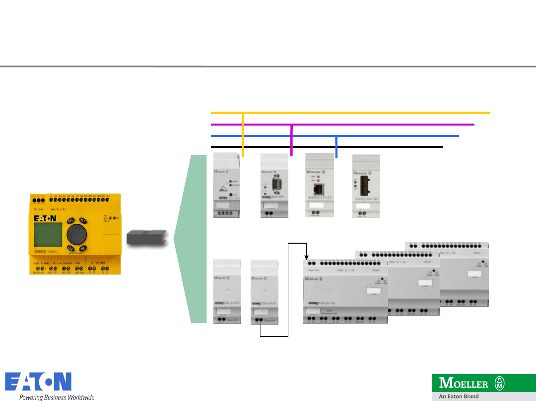
easySafety
Topology through easyLink
AS-I
Profibus DP
CANopen
DeviceNet
2 QR
6 QR
6 QR
8 QT
12DI AC
12DI DC
12DI DC
easyLink
4
1
41
09.06.2010
2009 Eaton Corporation. All rights reserved.
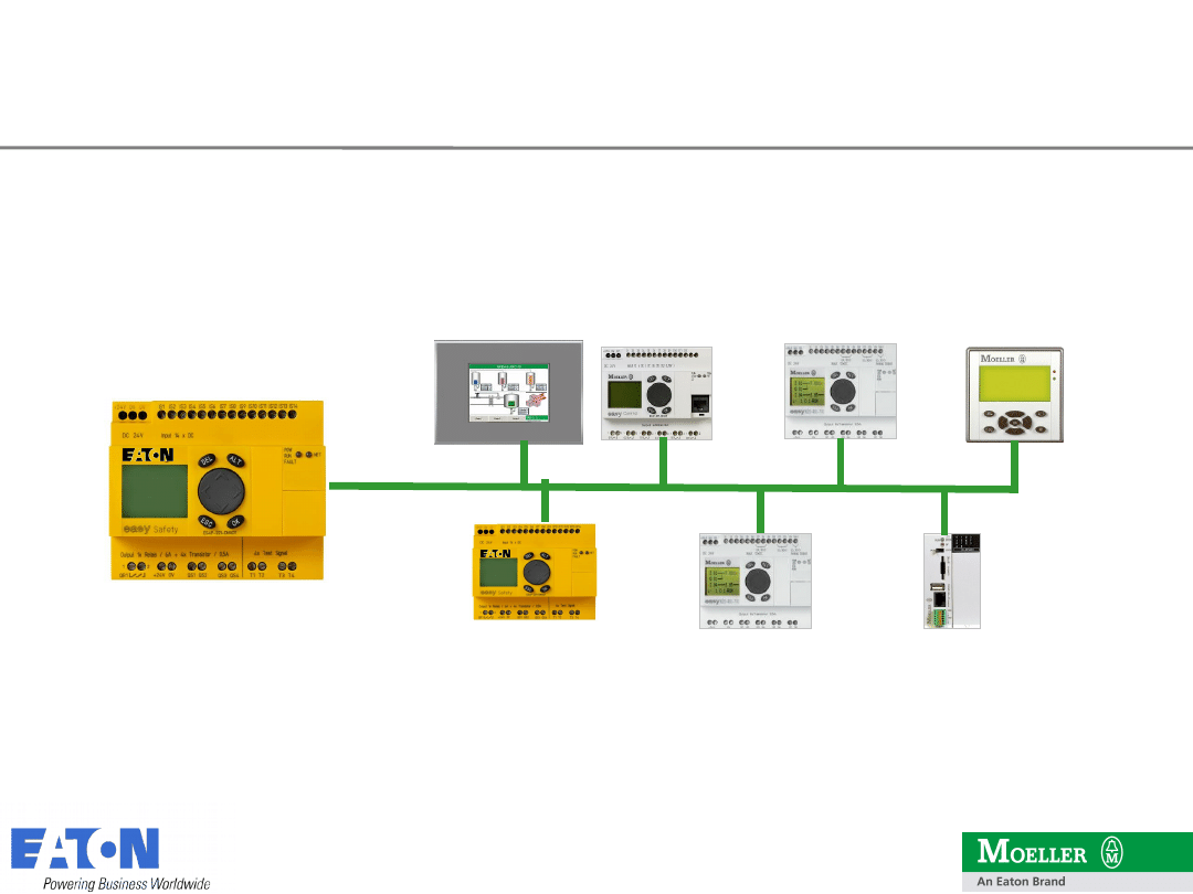
easy800
XC 100/200
MFD-Titan
MFD4
EC4P
easy Safety
easySafety
easyNet topology for up to 8 stations
easy800
4
2
42
09.06.2010
2009 Eaton Corporation. All rights reserved.
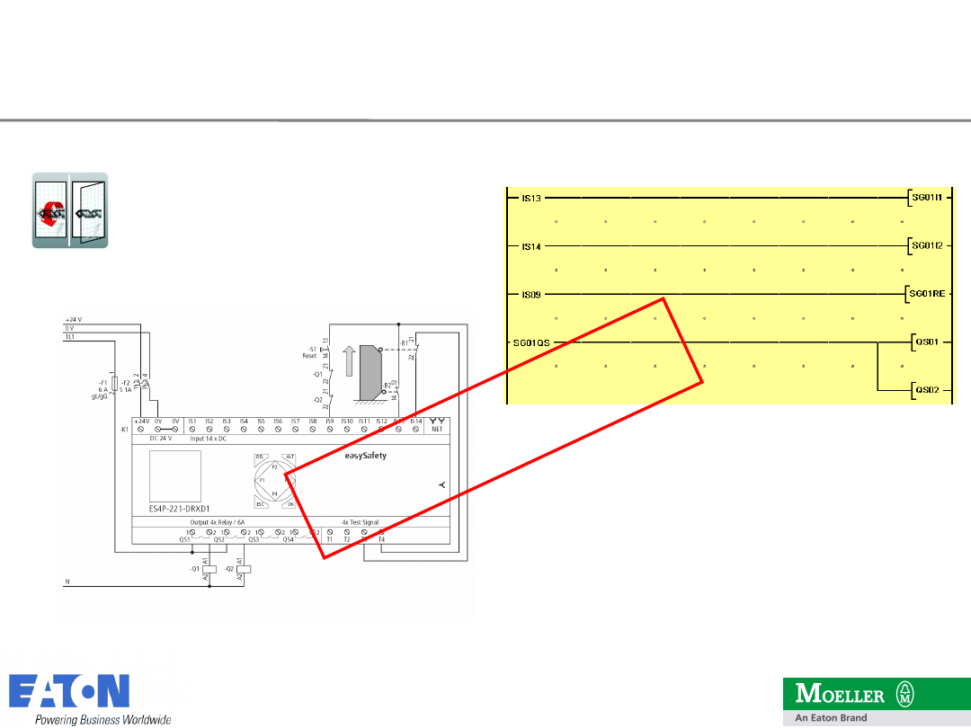
Wiring,
together with a short
and simple program,
provides a safety application that
meets the most stringent demands:
Category 4 according to EN 954-1
PL “e” according to EN ISO 13849-1
SIL 3 according to EN IEC 62061
It’s
ea
sy!
Example: Guard door with easySafety –
Cat. 4
4
3
43
09.06.2010
2009 Eaton Corporation. All rights reserved.
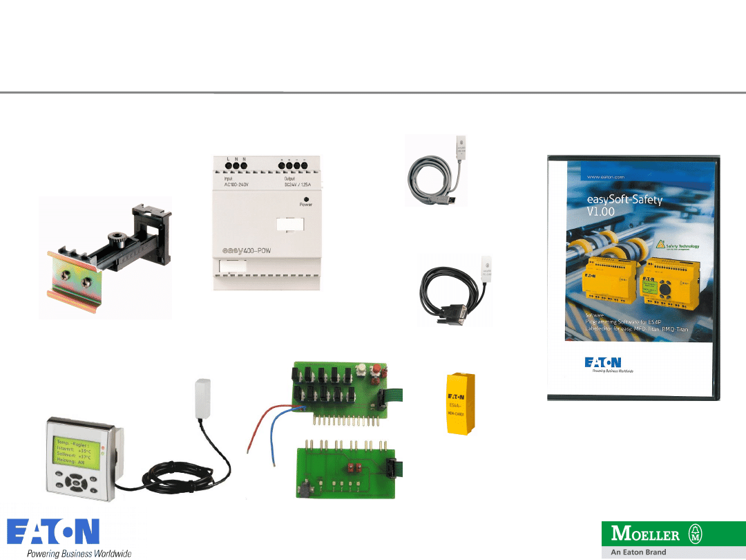
M22-TA
EASY-POW
ESP-SOFT
EASY800-USB-CAB
EASY800-PC-CAB
ES4A-MEM-CARD1
ES4A-221-DMX-SIM
easySafety
Accessories
MFD-CP4-800
4
4
44
09.06.2010
2009 Eaton Corporation. All rights reserved.
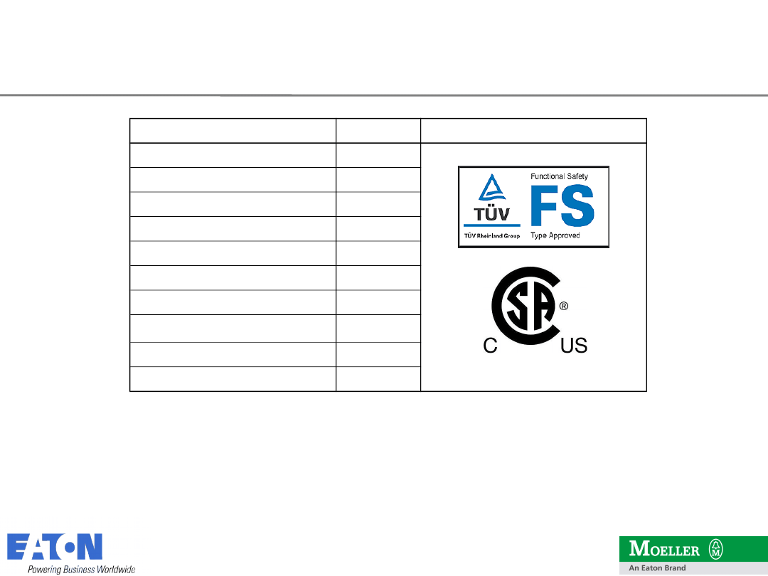
Ordering information
Type
Art. - Nr.
Approvals
ES4P-221-DMXX1
111016
ES4P-221-DMXD1
111017
ES4P-221-DRXX1
111018
ES4P-221-DRXD1
111019
ESP-SOFT (easySoft-Safety)
111460
ES4P-BOX-221-DMXD1
115126
ES4A-221-DMX-SIM
116953
EASY800-USB-CAB
106408
IL05013002Z
-
MN05013001Z-EN
121077
4
5
45
09.06.2010
2009 Eaton Corporation. All rights reserved.
http://
trainingscenter.moeller.net
http://
www.easy-forum.net
You will find supplementary notes
for our products, manuals,
installation instructions and PDF
catalogues on the Moeller support
pages.
You will find a host of applications,
programming examples and detailed
explanations for all function blocks
in the easy online training centre.
Exchange ideas with other easy
users in the easy forum.
http://www.moeller.net/support
easySafety
Information about the product
4
6
46
09.06.2010
2009 Eaton Corporation. All rights reserved.
Document Outline
- Safety Products ESR5 & easySafety
- Safety Technology Content
- ESR5 Safety Relays
- Folie 4
- Safety Functions
- Application example: Injection
- Positively actuated contacts
- Folie 8
- Folie 9
- Folie 10
- Folie 11
- Folie 12
- Folie 13
- Folie 14
- Folie 15
- Folie 16
- Folie 17
- Folie 18
- Folie 19
- Folie 20
- Folie 21
- Safety Relays ESR5 Competitors
- Slide 23
- Safety engineering Product portfolio
- easySafety Safety technology – Changes in standards
- easySafety Changed standards affect sensor diagnostics
- easySafety Advantages of easySafety
- Safety functions with ESR5 and easySafety
- easySafety All in One
- easySafety Features / Benefits and USP‘s
- easySafety Safety Inputs and Outputs
- easySafety Always the right model!
- easySafety Built-in interfaces easyNet and easyLink
- easySafety Topology through easyLink
- easySafety easyNet topology for up to 8 stations
- Example: Guard door with easySafety – Cat. 4
- easySafety Accessories
- Ordering information
- easySafety Information about the product
- Folie 46
Wyszukiwarka
Podobne podstrony:
Product presentation XC100FC
Product presentation easyControl
Product presentation XC200
product presentations R4Y6CKG4QRZXCXE6IRBMD7AXTEH2HL7FD5RACEI
Product presentation XC100
Product presentation XC121
Product presentation XIOC
Product presentation SmartWire DT
Product presentation XC100FC
Product presentation easyControl
Product presentation XC200
Presentationenzym
~$Production Of Speech Part 2
PRESENTATION
Presentation1(1)
AC31 Presentation
Presentation1 2
Wykład nr 5 podstawy decyzji producenta
159 Present Perfect
więcej podobnych podstron