BOOST CONVERTER DESIGN FOR 20KW WIND TURBINE GENERATOR
S. Jiao, D. Patterson and S. Camilleri
NT Center for Energy Research
Northern Territory University
Darwin, NT0909
Email: shuli.jiao@ntu.edu.au
Tel: 08-8946 6386 Fax: 08-8946 6993
Abstract
This paper presents the converter design for a 20kW wind turbine generator. The converter
consists of a phase controlled rectifier and a DC/DC boost converter. The rectifier makes the
generator AC voltage match the DC voltage while the boost converter keeps the DC voltage
constant. The generator's synchronous inductance acts as an AC inductor of boost converter so no
extra DC inductor is required. This converter is designed to be efficient and cheap. However, this
converter does result in higher power loss in the generator due to its non-sinusoidal phase current,
especially when the firing angle is not equal to 0.
1. POWER FLOW DIAGRAM
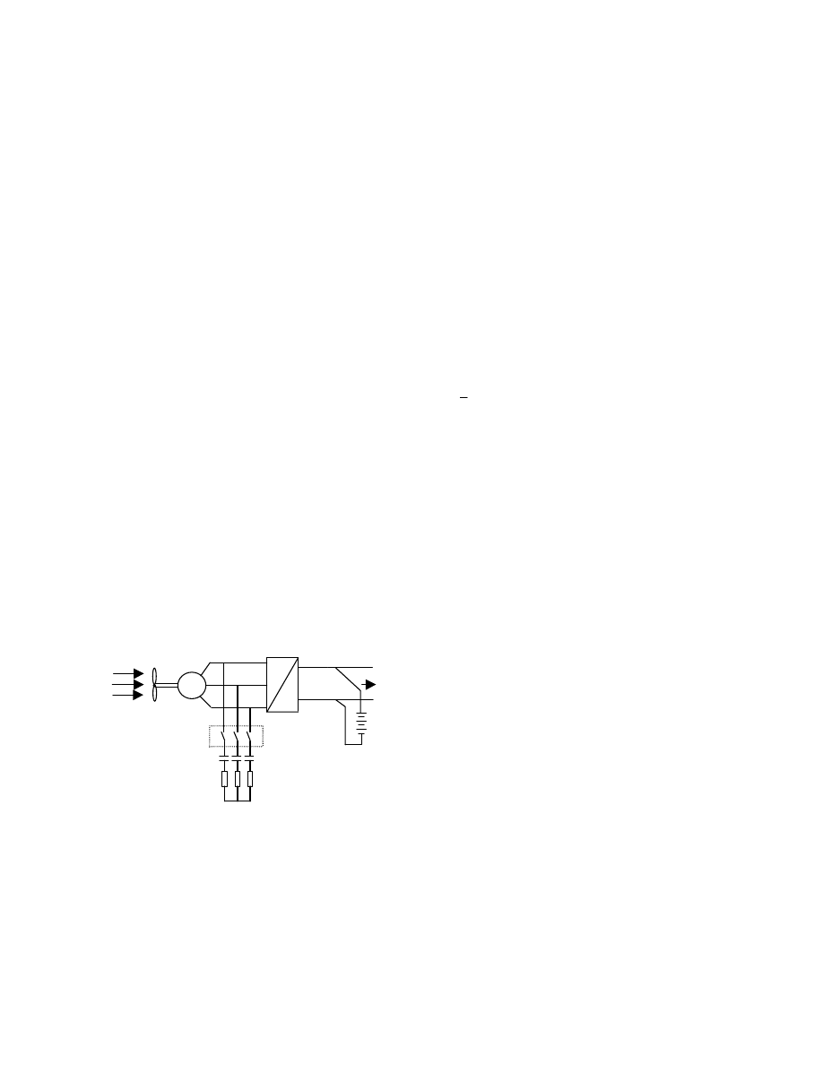
The power flow diagram for the 20kW wind generator
system is shown in Figure 1. The wind drives the wind
turbine, which is connected to the wind generator,
therefore the wind energy is converted to electrical
energy. The generator's AC voltage is converted to
DC voltage through an AC/DC converter. The DC
output voltage is fed to the load and battery bank. The
voltage should stay constant for various wind speeds.
When the wind speed is too high, i.e., the generator
produces too much power and voltage, the dump load
is connected through the switches. Also, the blade
pitch control can be employed in an emergency. When
the wind speed is low, the generator together with the
battery bank can provide sufficient energy to the load.
Figure 1. Power Flow Diagram of Wind Turbine System
In Figure 1, the battery bank is composed of 120
series connected Pd-Acid batteries, each at 2.35V and
all together at 282V. The rated speed is 10.5m/s wind
speed, 211rpm rotor speed. The wind turbine's cut-in
and cut-out wind speeds are 3m/s and 25m/s
respectively, corresponding to 60rpm and 266rpm
rotor speed. The wind energy P versus the wind
velocity v is expressed as:
3
2
1
v
AC
P
p
ρ
=
(1)
Where:
ρ
is the air density; A is the area of the air
interrupted by the wind turbine and C
p
is the
coefficient of the power of the wind turbine.
2. WIND GENERATOR
The wind generator is a three phase brushless
permanent magnet machine so the airgap flux
Φ can
be assumed to be constant. The back emf E
0
is
proportional to the rotor speed n, i.e.,
n
C
E
e
Φ
=
0
(2)
Where, C
e
is the voltage coefficient. The above
equation indicates how the wind energy is converted
to electrical energy. The generator outputs 20kW into
a resistive load at 211rpm, and up to 40kW with a
capacitive load at 266rpm for 3s or longer and
depending on its temperature rise before the overload.
The main features of the wind generator are shown in
appendix.
3. CONVERTER DESIGN
In order to make the generator's AC voltage match the
DC voltage, there are a few options. Firstly, the stator
of the generator is delta connected while the AC/DC
converter is composed of a three phase uncontrolled
rectifier and a boost converter [1]. Considering that
the synchronous inductance of the generator is large
enough to act as an AC inductor, therefore no extra
DC inductor with high frequency operation is needed
in the boost converter. The controller is cheap with
medium power loss. However, the large third
harmonics in the generator's phase voltage makes
delta connection impossible. Secondly, the stator of
G
AC
DC
Wind
BLDC
PM
Generator
Dump
Load
Switches
Load
Battery
the generator is star connected while the AC/DC
converter is composed of a three phase uncontrolled
rectifier and a buck-boost converter. The buck-boost
converter can step the DC voltage up and down,
however the main difficulty is that an extra DC
inductor with high frequency operation is essential
and the power loss of buck-boost converter is high as
well. The converter is more expensive with higher and
power loss comparing to the first converter.
Another solution is that the stator of the generator
remains star connected, while the converter employs a
phase-controlled rectifier and a boost converter. The
rectifier is used to match the generator's AC voltage
and the DC voltage while the boost converter keeps
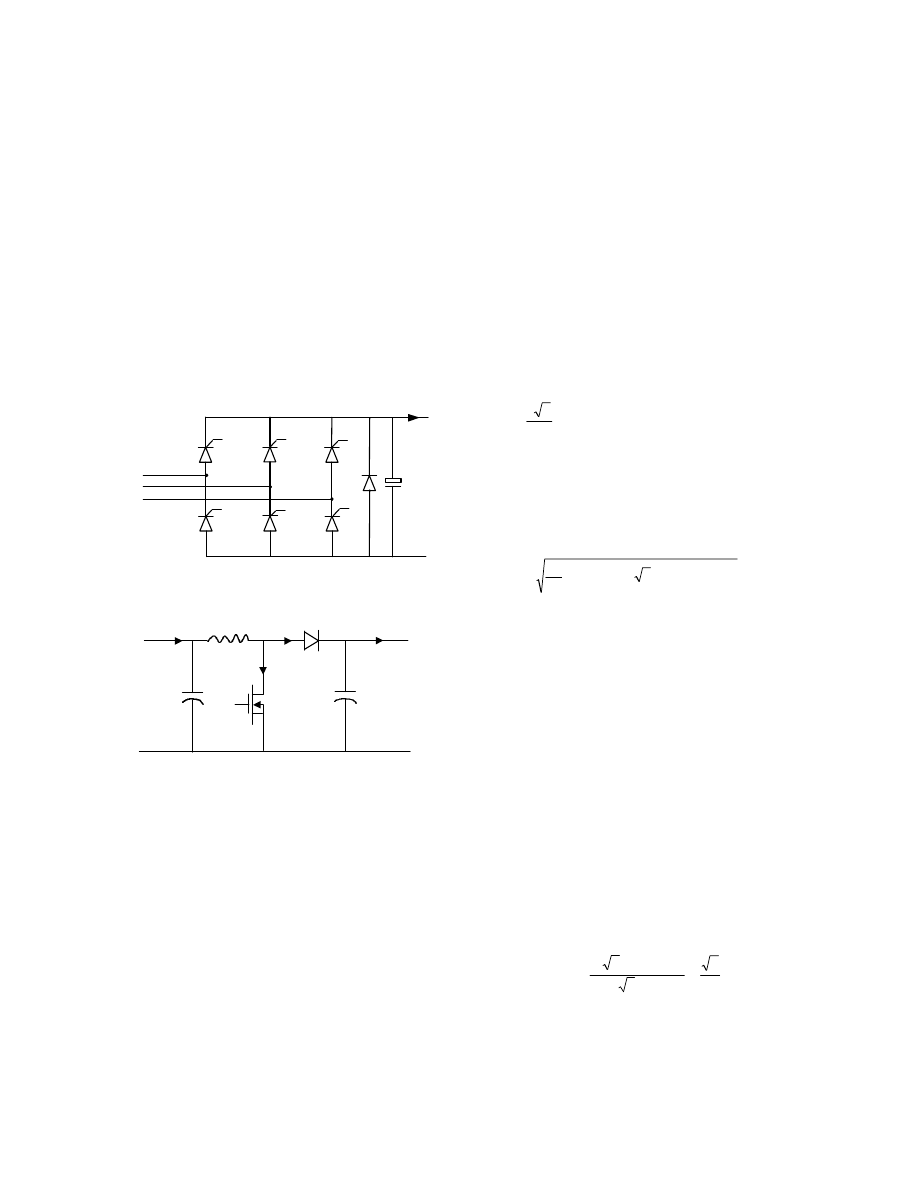
the DC voltage constant. The rectifier and the boost
converter are shown in Figure 2 and Figure 3
respectively.
Figure 2. Phase Controlled Rectifier
Figure 3. DC/DC Boost Converter
3.1 Phase-Controlled Rectifier
In Figure 2, the rectifier consists of six SCRs and a
free-wheeling diode that provides an additional path
for the load current and prevents negative values of
DC voltage from occurring. Generally, the rectifier
has three operation modes: (1) normal mode, for
example when SCR1 and SCR5 conduct. The rectifier
is likely to run at this mode considering the wind
generator's low speed operation. (2) commutation
mode, for example, when SCR1, SCR5 and SCR6
conduct. This is transition period between two
different normal modes. The commutation angle is not
negligible for this generator due to its large
synchronous reactance. (3) free-wheeling mode. This
happens when
α
>60
°
.
The advantage of a phase-controlled rectifier is that
the energy can not flow from DC side to the generator
while DC voltage is positive. However, it has some
drawbacks:
- the generator operates under unsymmetrical
load, especially at low speed.
- the phase current contains high harmonics that
increase the power loss and decrease the
efficiency.
At this stage, we neglect the commutation angle.
When the generator operates under rated speed
(n=211rpm) and rated power (P=20kW), the average
DC voltage V
avg
and its ripple are given by
U
V
V
line
avg
∆
−
α
π
=
2
cos
2
3
(3)
Here,
α
is the firing angle of SCRs. 2
∆
U is the
potential drop of the SCR and diode.
Initially, we assume
α
=0
°
, Under rated condition,
V
avg
=305.33V while 2
∆
U=3.2V.
V
d
V
V
V
avg
line
ripple
28
.
13
)
sin
2
(
2
6
3
/
2
3
/
2
=
θ
−
θ
×
π
=
∫
π
π
The average current depends on the load. Assume it is
20kW resistive load, the average and ripple current
are:
A
I
avg
50
.
65
=
,
A
I
ripple
84
.
2
=
. From the current
ripple, we can select the DC capacitor C
B
. Also, from
the maximum voltage and RMS current across the
SCR when the generator operates with 40kW
capacitive load, we can select the proper SCRs and
diode.
Assuming the load is resistive, the rectifier's DC
current and other quantities can be estimated by the
following procedures:
(1) find power P from equation (1)
(2) find fundamental frequency f from rotor speed n
(3) find back emf E
0
from equation (2)
(4) estimate the phase current from the DC current as
DC
line
DC
line
line
phase
I
V
I
V
I
I
π
=
π
=
=
6
3
)
/
2
3
(
(4)
(5) from the generator's vector diagram,
L
S
D
C
y
z
x
+
_
V
1
I
1
i
z
i
y
+
_
_
+
V
2
I
2
v
xz
C
1
SCR1
SCR4
SCR6
SCR5
SCR2
SCR3
V
a
V
b
V
c
+
_
V
I
C
B
D
]
)
2
(
[
)
6
(
3
2
)
6
3
(
]
)
2
(
[
)
6
(
]
6
3
[
]
6
[
2
)
6
3
(
)
2
(
)
(
2
2
2
2
2
2
2
2
2
2
2
2
2
2
2
2
0
a
DC
DC
a
DC
DC
DC
DC
a
phase
phase
phase
fL
R
I
RP
V
fL
R
I
V
R
I
V
fL
I
R
I
V
E
π
+
π
+
+
π
=
π
+
π
+
π
×
π
×
+
π
=
π
+
+
=
hence,
]}
)
2
(
[
)
6
(
3
2
{
)
6
3
(
2
2
2
2
2
0
2
2
a
DC
DC
fL
R
I
RP
E
V
π
+
π
−
−
π
=
(5)
(6) put equation (3) (neglect diode voltage drop
3.2V), (4), (5) into DC power equation i.e.,
2
2
2
DC
DC
I
V
P
=
. Solving this second order
algebraic equation, we can get the DC current,
]
)
2
(
[
216
.
1
]
)
2
(
[
4445
.
0
)
3
2
(
3
2
2
2
2
2
2
2
2
0
2
0
a
a
DC
fL
R
fL
R
P
RP
E
RP
E
I
π
+
π
+
−
−
−
−
=
(6)
For instance, when n=211rpm, E
0
=196.55V, P=20kW,
R=0.2873
Ω
, L
a
=6.514mH, f=63.3Hz, from the above
equation, I
DC
=63.26A, there is 3.3% error due to the
above assumptions such as neglecting of commutation
angle, voltage drop of diode,
α
=0
°
at this stage etc.
Here we can put a correcting factor k=1.033 in
equation (6) to reduce the error.
(7) find other quantities such as V
DC
etc. Here, V
DC
may be greater than V
2
=282V, e.g., under rated
condition. Then we need adjust the firing angle to
limit V
DC
to 282V. It follows in next step.
(8) if V
DC
≤
282V,
α
=0
°
if V
DC
>282V, find
α
from Equation (3), i.e.,
(neglecting 2
∆
U)
)
V
282
(
cos
DC
1
−
=
α
(15)
in this case, V
DC(new)
=282V.
(9) correct the I
DC
by I
DC(new)
=P/282 if V
DC
is greater
than 282V in order to output the same power.
Note that, it is assume that the fundamental
frequency of line voltage and current stay the
same as before because the power output does not
change. Therefore, we need not correct the AC
values.
For example, under the rated operating condition,
V
DC
=305.33V I
DC
=65.5A for diode rectifier, while
α=22
.54
°
, V
DC
=282V, I
DC
=70.93A for the phase-
controlled rectifier.
The switching power losses are very small for SCRs
due to low frequency operation, hence the overall
power loss of the rectifier P
B
can be taken as its
conduction loss expressed by
)
(
)
(
2
6
)
3
/
(
AV
F
TM
AV
F
TM
B
I
V
I
V
P
=
×
=
(7)
Where, V
TM
is the on-state voltage and I
F(AV)
is the
average forward current. The total loss of rectifier
under rated condition is 227W.
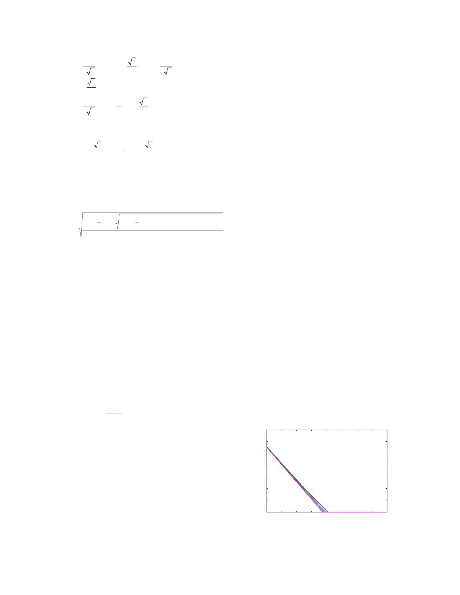
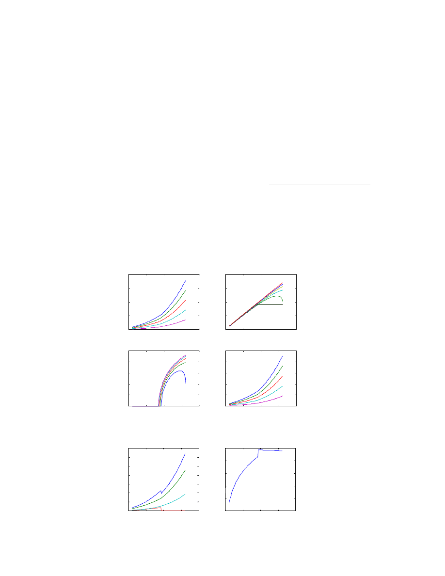
Figure 4 shows the rectifier's performance versus the
rotor speed with different loads, i.e., 1.0, 0.8, 0.6, 0.4,
0.2 rated load. V
1
represents the DC voltage fed to
DC/DC converter whilst V
DC
for the DC voltage in
case of diode rectifier, i.e.,
α
=0
°
. At rated load, the
rectifier takes effect for the speeds over 142rpm,
below this speed, the DC/DC boost converter is
needed to boost the DC voltage up.
3.2 DC/DC Boost Converter
The DC/DC converter is chosen to be a direct boost
converter as shown in Figure 3. Initially, it is assumed
that there is no power loss in the converter. The
voltage and current relationships between the primary
and secondary sides are shown in Equation (8) and (9)
respectively.
D
V
V
−
=
1
/
2
1
(8)
D
I
I
−
=
1
/
1
2
(9)
Here, D stands for the duty ratio, which is defined as
the ratio between the conduction time of the switch
TR and the duty period. When the generator operates
under rated condition, V
1
=V
2
=282V, I
1
=I
2
=70.92A,
hence D=0. The duty ratio versus rotor speed under
different loads is shown in Figure 5.
Figure 5. Duty Ratio versus Rotor Speed
with 1.0, 0.8, 0.6, 0.2 rated Loads
60
80
100
120
140
160
180
200
220
0
0.1
0.2
0.3
0.4
0.5
0.6
0.7
D
n(rpm)
0.2…1.0
From Figure 4 and Figure 5, it can be seen that the
converter is structured as a rectifier and a boost
converter. When the line voltage of generator is high,
the rectifier takes effect while D=0; on the other hand,
when the voltage of generator is low, the boost
converter takes effect while
α
=0
°
.
The ripple in V
2
should not be too high as the
secondary side of the boost converter is connected to
the battery bank. The primary side of the boost
converter is connected to the turbine generator via the
rectifier. The ripple in I
1,
which introduces power loss
in the generator, could be high, e.g., if the current
ripple is 10% of the DC current, the copper loss is 1%
of the main copper loss, which is only a small part of
the power loss. Note that the capacitor C
B
of the
rectifier takes the effect of C
1
. The primary voltage is
assumed to contain no harmonics after the capacitor
C
B
, therefore, the values of L and C should be
2
2
)
1
(
v
T
D
I
C
∆
−
≥
(10)
1
1
)
1
(
i
T
D
V
L
∆
−
≥
(11)
Where,
∆v
2
,
∆i
1
are voltage and current ripples
respectively. Assuming f
s
=20KHz, T=50
µ
s. Let
%
5
/
2
2
≤
∆
V
v
and
%
10
/
1
1
≤
∆
I
i
, we get C>155.4uF,
L>1.229mH.
The generator's phase inductor can be used as AC
inductor L while a DC inductor is not necessary [3-5].
There are two phases conducting at each time, so
L=2L
phase
=2
×
(2/3)
×
6.514 =8.685mH, which is larger
than required value.
In Figure 3, it is assumed that all the DC components
of current across the diode pass to the secondary side
of boost converter that forms the current I
2
while the
AC component passes to the capacitor C, the current
ripple across C in RMS value is estimated by
1
2
1
2
1
)
1
(
]
)
1
[(
)
1
(
)
(
I
D
D
D
I
D
D
DI
I
C
×
−
=
−
+
−
=
(12)
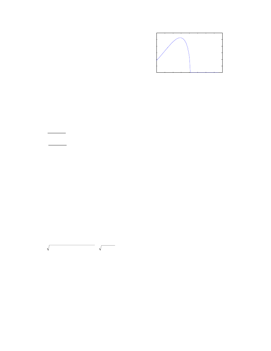
The current ripple in capacitor I
C
versus rotor speed
with full load given by Equation (1) is shown in
Figure 6. Its maximum current is I
Cmax
=5.26A which
occurs at n=118rpm with the power of 1768W. At this
stage, we can choose the proper capacitor.
The power losses of the boost converter are mainly
from the diode and switch (MOSFET). For the diode,
the conduction loss is dominant which is expressed by
2
)
(
)
(
0
RMS
F
t
AV
F
t
D
I
r
I
V
P
+
=
(12)
Figure 6. The Current Ripple in Capacitor C
Where, I
F(AV)
=(1-D)I
1
; I
F(RMS)
=(1-D)
0.5
I
1
; V
t0
is the
threshold voltage and r
T
is the slope resistance.
On the other hand, the power loss of MOSFET P
M
are
determined by its conduction loss P
M1
, off switching
loss P
M2
and on switching loss P
M3
. They are
)
(
2
1
1
on
DS
M
R
DI
P
=
(13)
f
s
M
t
f
I
V
P
1
1
2
=
(14)
r
s
M
t
f
I
V
P
1
1
3
=
(15)
Where, R
DS(on)
is the drain-source on-state resistance; t
f
and t
r
are current fall and rise time respectively.
The total losses of the boost converter are the
summation of the losses of the rectifier and the boost
converter. The total power losses and efficiencies can
be seen from Figure 7. It can be seen that The
maximum power loss is 320W when n=211rpm with
rated load. The maximum efficiency is 98.44% when
n=143rpm with 6226W output while the minimum
efficiency is 96.31% when n=60rpm with 459.87W.
4. CONCLUSION
The rectifier and the boost converter are designed for a
20kW wind generator. At various wind speeds, all the
quantities of the system including AC, DC voltages
and currents, duty ratio, power loss and efficiency can
be estimated through mathematical methods. The
generator's synchronous inductance is large enough to
act as the AC inductor of the boost converter,
therefore no extra DC inductor is required.
When the line voltage is too high, phase-controlled
rectifier is employed to limit the primary DC voltage
hence the duty ratio of boost converter is set to 0. In
this case, the power loss mainly originates from the
rectifier. On the other hand, when the line voltage is
low, set the firing angle of rectifier to 0 and the
primary voltage can be boosted to that of battery bank
through the boost converter. In this case, the power
loss of boost converter is still very low due to the low
current. Therefore, the converter is designed to be
very efficient.
60
80
100
120
140
160
180
200
220
0
1
2
3
4
5
6
IC
(A
)
n(rpm)
However, this converter does result in higher power
loss in the generator due to its non-sinusoidal phase
current, especially when the firing angle is not equal
to 0. A six switch voltage source converter with
closed loop current control can provide sinusoidal
current, unity power factor but it is more expensive.
The latter converter is beyond this paper and will be
introduced later.
5. ACKNOWLEGEMENT
The authors would like to thank Australian CRC for
Renewable Energy Ltd (ACRE) for the financial
support and technical support from ACRE and UTS.
6. REFERENCES
[1] Jiao, S. and Patterson, D., “Converter Design for
20kW Wind Turbine Generator with Delta
Connection”, Internal Report of ACRE, April,
1999.
[2] Jiao, S. and Patterson, D., “Buck-Boost Converter
Design for 20kW Wind Turbine Generator with
Star Connection”, Internal Report of ACRE, May,
1999.
[3] Salmon, J. C., “Reliable 3-phase PWM Boost
Rectifier Employing a Staked Dual Boost
Converter Subtopology”, IEEE Trans. on Industry
Applications, Vol. 32, No. 3, May/June 1996,
PP542-551.
[4] Salmon, J. C., “Techniques for Minimizing the
Input Current Distortion of Current-Controlled
Single Phase Boost Rectifiers”, IEEE Trans. on
Power Electronics, Vol. 8, No. 4, October 1993,
PP509-520.
[5] Salmon, J. C., “Circuit Topologies for Single-
Phase Voltage-Doubler Boost Rectifiers”, ibid,
PP542-551.
[6] Fisher, F. J., “Power Electronics”, PWS-Kent
Publishing Company, 1991.
APPENDIX: Features of 20kW Wind Generator
Rated Power Output:
20kW
Rated Speed:
211rpm
Stator Winding Connection:
star
Number of Rotor Poles:
36
Stator Phase Resistor:
0.2873
Ω
Synchronous inductance:
6.514mH
Rated Phase Current:
50.6A
Rated Phase Voltage:
131.9V
Figure 4. Performance of Phase-controlled Rectifier under 1.0, 0.8, 0.6, 0.4, 0.2 Rated Load
Figure 7. Total Power Loss and Efficiency versus Rotor Speed
50
100
150
200
250
0
20
40
60
80
ID
C
(A
)
n(rpm)
50
100
150
200
250
100
200
300
400
500
V
1
,V
D
C
(V
)
n(rpm)
50
100
150
200
250
0
10
20
30
40
50
a
(d
e
g
re
e
)
n(rpm)
50
100
150
200
250
0
50
100
150
200
250
P
B
(w
)
n(rpm)
1.0
…
0.2
0.2
…
1.0
0.2
…
1.0
1.0
…
0.2
50
100
150
200
250
0
50
100
150
200
250
300
350
,P
(t
o
ta
l)
,P
B
,P
M
,P
D
(W
)
n(rpm)
50
100
150
200
250
96
96.5
97
97.5
98
98.5
E
i(
%
)
n(rpm)
P
total
P
B
P
D
P
M
Document Outline
- Contents
Wyszukiwarka
Podobne podstrony:
CEI 61400 22 Wind turbine generator systems Required Design Documentation
CEI 61400 22 Wind turbine generator systems Required Design Documentation
DC DC Converter for EWB Wind Turbine Project review
[2006] Application of Magnetic Energy Recovery Switch (MERS) to Improve Output Power of Wind Turbine
20060028025 Wind Turbine Generator System
(WinD Power) Dynamic Modeling of Ge 1 5 And 3 6 Wind Turbine Generator {}[2003}
IEC 61400 11 Wind turbine generator systems en
20050253396 Variable Speed Wind Turbine Generator
ANALYSIS OF CONTROL STRATEGIES OF A FULL CONVERTER IN A DIRECT DRIVE WIND TURBINE
Wind Turbine Generator Rotor Construction (BackHome Magazine)(2s)
Development Of A Single Phase Inverter For Small Wind Turbine
The Material Selection for Typical Wind Turbine Blades 2006
20060028025 Wind Turbine Generator System
DIN 61400 21 (2002) [Wind turbine generator systems] [Part 21 Measurement and assessment of power qu
[Engineering] Electrical Power and Energy Systems 1999 21 Dynamics Of Diesel And Wind Turbine Gene
[2006] Application of Magnetic Energy Recovery Switch (MERS) to Improve Output Power of Wind Turbine
więcej podobnych podstron