
Dynamics of diesel and wind turbine generators on an isolated power
system
D. Das
a,
*, S.K. Aditya
a
, D.P. Kothari
b
a
Electrical Eng. Dept., Indian Institute of Technology, Kharagpur—721302, India
b
Centre for Energy Studies, Indian Institute of Technology, New Delhi—110016, India
Abstract
The paper presents dynamic system analysis of an isolated electric power system consisting of a diesel generator and a wind turbine
generator. The 150 kW wind turbine generator is operated in parallel with a diesel generator to serve an average load of 350 kW. Time
domain solutions are used to study the performance of the power system. Optimum values of gain settings of the Proportional-Integral
controller (P-I) are obtained by using the integral squared error (ISE) technique. A simple variable structure control (VSC) logic is also
proposed for improvement of the dynamic performance of the system.
䉷 1998 Elsevier Science Ltd. All rights reserved.
Keywords: Wind and diesel power system; Stability; Optimization
1. Introduction
A constantly increasing power demand has to be met
through an adequately planned electrical power generation
programme. Electrical energy is environmentally the most
benign form of energy, with production routed through
conventional fossil fuel burning or through nuclear energy
and wherever possible through hydro resources. All of these
in addition to other disadvantages give rise to environmental
issues of a varied nature. Therefore it is necessary to
consider the problems of electrical energy generation and
environment jointly so that the increasing need of electricity
for industrialization will be met with minimal environmen-
tal degradation. One of the solutions is to utilize wind
energy in favourable sites which are remote from centralised
energy supply systems. Since wind power varies randomly
there must be a stand-by power source to meet load demand.
The diesel and wind system is one of the hybrid systems
utilizing more than one energy source. A wind and diesel
system is very reliable because the diesel acts as a cushion to
take care of variation in wind speed, and would always
provide power equal to load minus the wind power.
Scott et al. [1] have investigated the dynamic interaction
to quantify any increased disturbance to the Block Island
Power Company (BIPCO), on Block Island (which operates
an isolated electric power system consisting of diesel and
wind turbine generators resulting from connection of the
MOD-OA wind turbine generator). In this study, the
dynamic simulation of the wind turbine generator operated
in parallel with a diesel generator on an isolated power
system is carried out. Optimum values for the gain settings
of the Proportional-Integral (P-I) controller have been
obtained using the Integral Squared Error (ISE) technique.
A simple Variable Structure Control (VSC) logic is also
proposed for the improvement of system dynamic perfor-
mance.
2. Description of diesel and wind systems
The model considered in this study consists of the follow-
ing sub-systems [1,3,4]:
Wind dynamics model;
Diesel dynamics model;
Blade pitch control of wind turbine;
Generator dynamics model.
The wind model is one feature that is unique to the wind
turbine generator and is not required for the diesel generator
system in the stability programme. Anderson et al. [2] have
presented one model that can properly simulate the effect of
wind behaviour, including gusting, rapid (ramp) changes
and background noise. The basic conditions for start up
and synchronization are that the wind speed is to be within
an acceptable range and there must be a phase match
between the generator and system voltages [1].
The diesel dynamics is associated with diesel power and
the nature of the dynamic behaviour in this model is
Electrical Power and Energy Systems 21 (1999) 183–189
JEPE 278
0142-0615/99/$ - see front matter
䉷 1998 Elsevier Science Ltd. All rights reserved.
PII: S 0 1 4 2 - 0 6 1 5 ( 9 8 ) 0 0 0 3 3 - 7
* Corresponding author; e-mail: ddas@ee.iitkgp.ernet.in.
dominated by the diesel speed governor controller. A total
power set point is selected in which it can manually adjusted
from zero to maximum value. The purpose of the adjustable
power set point is to allow system utility personnel to lower
the power setting below the maximum settings of the wind
generator to prevent controlling diesel from dropping to less
than 50% of the rated power. Operation of a diesel engine
for extended periods at two power levels could result in
possible engine damage.
Pitch control has the potential for producing the highest
level of interaction because of the presence of both diesel
and wind turbine control loops. The pitch control system
consists of a power measurement transducer, a manual
power set point control, a proportional plus integral feed-
back function, and a hydraulic actuator which varies the
pitch of the blades. Turbine blade pitch control has a signif-
icant impact on the dynamic behaviour of the system. This
type of control only exists in horizontal axis machines.
Variable pitch turbines operate efficiently over a wider
range of wind speeds than fixed pitch machines. However,
cost and complexity are higher.
The generator dynamics model consists of a synchronous
generator driven by a diesel engine through a flywheel and
connected in parallel with an induction generator driven by
a wind turbine. The diesel generator will act as a dummy
grid for the wind generator which is connected in parallel.
Variations of electrical power due to changes in wind speed
should be as small as possible; this is obtained by using the
induction generator as a wind turbine drive train. Unlike
synchronous generators, induction generators are high
compliance couplings between the machine and the electri-
cal system. This is true for induction generators with slip of
at least 1–2% at rated power. The controlled variables are
turbine speed and shaft torque. Control acts on the turbine
blade pitch angle (pitch control). Since the torque speed
characteristic of the induction generator is nearly linear in
D. Das et al. / Electrical Power and Energy Systems 21 (1999) 183–189
184
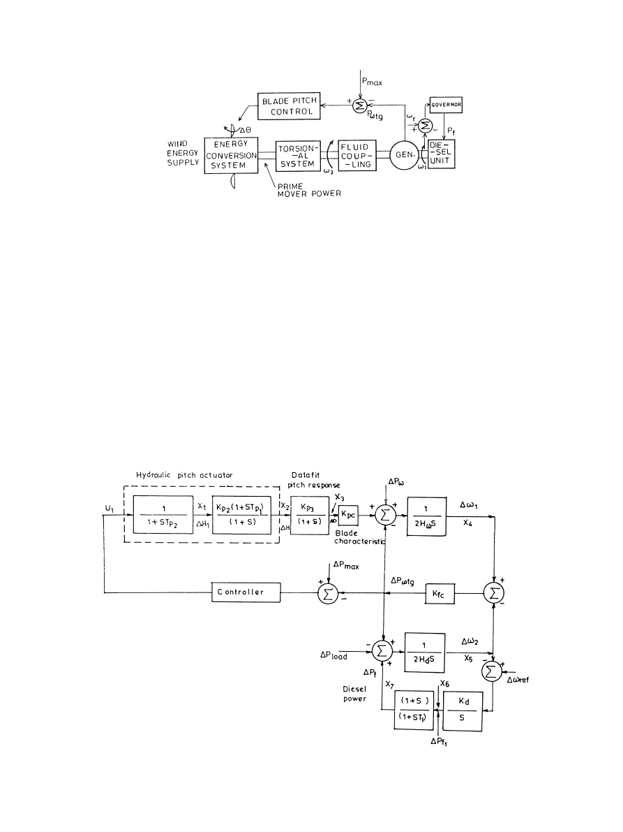
Fig. 1. Conceptual model of diesel and wind turbine generator system.
Fig. 2. Functional block diagram for wind and diesel systems with pitch control.
the operating region, torque changes are reflected as speed
changes. Therefore, it is possible to provide a single speed
controller to control speed as well as torque.
3. Mathematical model of the system
A linear model is formulated for the wind and diesel
turbine generator system for the purpose of identifying
and quantifying the underdamped oscillation. This objective
is met by retaining the pertinent controller dynamics for
both the diesel unit governors and wind turbine generator
pitch controller/actuator. The conceptual model that results
is shown in Fig. 1. The fluid coupling shown in Fig. 1
transfers speed difference into power. The actual function
is nonlinear (Square law) but for the model it is linearized,
resulting in a constant for the particular power set point
selected. Fig. 2 shows the functional block diagram that is
obtained.
The transfer function of the hydraulic pitch actuator is
given as:
DH S
U
1
S
K
p2
1 ⫹ ST
p1
T
k
S
2
⫹ ST
p2
⫹ 1 1 ⫹ S
1
But T
k
is very small compared to T
p2
and hence T
k
is
neglected from the mathematical model. Therefore Eq. (1)
can be written as
DH S
U
1
S
K
p2
1 ⫹ ST
p1
1 ⫹ ST
p2
1 ⫹ S
2
The transfer function Eq. (2) of the hydraulic pitch actua-
tor is split into two blocks (Fig. 2) and
DH
1
is a dummy
variable.
The transfer function of the diesel governor (Fig. 2) is
given as:
DP
f
S
D
v
ref
S ⫺ D
v
2
S
K
d
1 ⫹ S
S
1 ⫹ ST
1
3
As
v
ref
is the reference speed setting (a constant) for the
diesel generator, therefore
Dv
ref
0.0. Substituting Dv
ref
0.0 in Eq. (3), we get
DP
f
S
⫺ D
v
2
S
K
d
1 ⫹ S
S
1 ⫹ ST
1
4
The transfer function of the diesel governor Eq. (4) is split
into two blocks and
DP
f1
is a dummy variable.
Appearing in a block (Fig. 2) labelled ‘data fit pitch
response’ is a simple lag which is required to match the
phase/gain characteristic of the model. Other state variables
are marked in Fig. 2. The system is a linear continuous-time
dynamic system and can be represented by a set of linear
differential equations of the form:
_X AX ⫹ BU ⫹ GP
5
where X, U and P are state, control and disturbance vectors
and A, B and
G are constant matrices associated with them
respectively. For this system (Fig. 2), X, U and P are
given as
X
0
DH
1
DH DD D
v
1
D
v
2
DP
f 1
DP
f
6
U
U
1
7
P
0
DP
v
DP
load
8
where,
0
stands for transpose. A, B and
G are given in
Appendix
1.
Data
for
this
system
are
given
in
Appendix 2.
D. Das et al. / Electrical Power and Energy Systems 21 (1999) 183–189
185
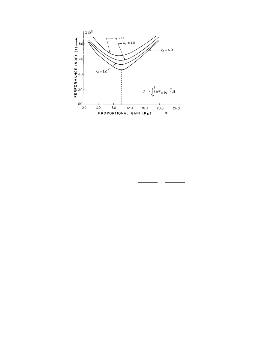
Fig. 3. K
p
vs J for several values of K
I
.
4. Optimization of the Proportional-Integral (P-I)
controller gain settings using the ISE technique
Many utilities prefer to use the P-I controller for
better system dynamic response and in the present
study, the P-I controller is used. The P-I control law
is given as
U
1
K
p
DP
max
⫺ DP
vtg
⫹ K
I
Z
t
0
DP
max
⫺ DP
vtg
dt 9
For the study system, P
max
150 kW is constant, there-
fore
DP
max
0.0. Substituting DP
max
0.0 in Eq. (9)
we obtain
U
1
⫺K
p
DP
vtg
⫺ K
I
Z
t
0
DP
vtg
dt
10
An attempt is made to obtain the optimum values of P-I
gain settings (K
p
and K
I
) using the integral squared error
(ISE) technique for a 1% step increase of load.
A performance index
J
Z
t
0
DP
vtg
2
dt
11
is minimized to obtain the optimum values for P-I gain
settings. Note that
DP
vtg
is also a function of
Dv
1
and
Dv
2
(Fig. 2).
Fig. 3 shows the plot of J vs K
p
for several values of
K
I
, where K
p
and K
I
are proportional and integral gains
D. Das et al. / Electrical Power and Energy Systems 21 (1999) 183–189
186
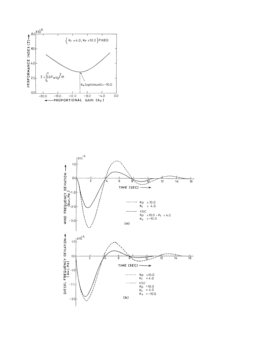
Fig. 4. Plot of K
v
vs J.
Fig. 5. Frequency responses with conventional and variable structure controllers.
respectively. From Fig. 3, it is seen that K
p
10:0 and K
I
4
:0 are more or less optimum values of P-I gain settings.
5. Variable structure control (VSC) logic
In this study, an attempt is also made to improve the
system dynamic performance by using a simple variable
structure control (VSC) logic which is based on proportional
(P) and proportional-integral (P-I) control concept. If the
control law applied at the first stage of the transient (as
long as error is sufficiently large) is chosen as
U
1
⫺K
v
DP
vtg
if
兩DP
vtg
兩典
1
12
where
1
⬎ 0 is some constant, but when the error is small
the control law is
U
1
⫺K
p
DP
vtg
⫺ K
I
Z
t
0
DP
vtg
dt if
兩DP
vtg
兩 ⱕ
1
13
where
兩DP
vtg
兩典
1
for t
ⱖ t
1
, then if the parameters K
v
, K
p
, K
I
and
1 are suitably selected, one can ensure a high-quality
transient response, distinguished by good dynamic and
steady-state characteristics. Indeed taking the magnitude
of K
v
as being sufficiently large, one can make sure that
the speed of the system is high; thus, the error
DP
vtg
, in
response to a step input rapidly enters the region
兩DP
vtg
兩 ⱕ
1
. At the instant t
1
, when the error has fallen to
1, the structure of the controller is changed by switching to a
P-I control, which eliminates the steady error remaining in
the system.
An attempt is made to obtain optimum values of K
v
by
using the ISE technique. The same performance index J Eq.
(11) is chosen to obtain the optimum values of K
v
. Through-
out this optimization process, values of K
p
and K
I
are fixed at
10.0 and 4.0, respectively. Fig. 4 shows the plot of J vs K
v
for
1 0.0004. It is worth mentioning here that several
values of
1 are tried out. However, 1 0.0004 gives the
lowest value of J. From Fig. 4, it is seen that the optimum
value of K
v
is
⫺ 10.0. However, any positive value of K
v
does not minimize the performance index J Eq. (11) and
perhaps this is due to excessive control action.
6. Dynamic responses
Figs. 5 and 6 show the dynamic responses for a 1% step
increase of load with the P-I controller and variable struc-
ture controller (VSC). It is seen that the activation of pitch
control with the conventional P-I controller results in an
underdamped response. Although this is a stable response,
the low damping allows the oscillation to continue for a
D. Das et al. / Electrical Power and Energy Systems 21 (1999) 183–189
187
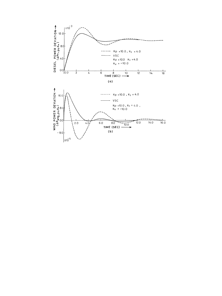
Fig. 6. Power responses with conventional and variable structure controllers.

longer time before damping out. It is seen that with the use
of VSC, damping is greatly improved. Peak wind generator
frequency deviation (Fig. 5(a)) and peak diesel power devia-
tion (Fig. 6(a)) are much less compared to the conventional
P-I controller. From Fig. 6(b), it is also seen that with the use
of VSC, the wind power deviation (
DP
vtg
) is slow and
monotonic and hence is preferred. From Figs 5 and 6, it is
also seen that with the use of VSC, settling time is much less
compared to that of the conventional P-I controller. There-
fore, it can be concluded that the variable structure control-
ler improves the system damping compared to the fixed
structure P-I controller.
7. Conclusions
A linear mathematical model of the wind and diesel turbine
generators operating on an isolated electric power system has
been formulated for the purpose of identifying and quantifying
the underdamped oscillation. The simulation incorporates
wind turbine pitch control and diesel governor. Optimum
values for the gain parameters of the conventional propor-
tional-integral (P-I) controller and variable structure controller
(VSC) have been obtained using the integral squared error
(ISE) technique. Analysis reveals that the variable structure
controller gives better dynamic performance in terms of peak
deviations and settling time compared to that of the conven-
tional fixed structure P-I controller.
It can also be concluded that wind turbine generation,
even when providing a large proportion of the power
required by an isolated utility can be a practical option
resulting in system disturbances no greater than those
found in a conventional diesel system.
Appendix 1
A, B and
G matrices of the system (Fig. 2) are given
below:
Note that B is a 7
× 1 matrix because there is only one
control input.
Appendix 2
Area capacity
; P
R
350 kW;
H
v
inertia constant on machine base
3
:5 s for wind system;
H
d
inertia constant on machine base
8
:5 s for diesel system;
D. Das et al. / Electrical Power and Energy Systems 21 (1999) 183–189
188
A
⫺1
T
p2
0
0
0
0
0
0
K
p2
⫺
K
p2
T
p1
T
p2
!
⫺1
0
0
0
0
0
0
K
p3
⫺1
0
0
0
0
0
0
K
pc
2H
v
⫺K
fc
2H
v
K
fc
2H
v
0
0
0
0
0
K
fc
2H
d
⫺K
fc
0
1
0
0
0
0
⫺K
d
0
0
0
0
0
0
⫺K
d
T
1
1
T
1
⫺1
T
1
2
6
6
6
6
6
6
6
6
6
6
6
6
6
6
6
6
6
6
6
6
6
6
6
6
6
6
6
4
3
7
7
7
7
7
7
7
7
7
7
7
7
7
7
7
7
7
7
7
7
7
7
7
7
7
7
7
5
B
1
T
p2
K
p2
T
p1
T
p2
0
0
0
0
0
2
6
6
6
6
6
6
6
6
6
6
6
6
6
6
6
6
6
6
6
6
6
4
3
7
7
7
7
7
7
7
7
7
7
7
7
7
7
7
7
7
7
7
7
7
5
; G
0
0
0
0
0
0
1
2H
v
0
0
⫺1
2H
d
0
0
0
0
2
6
6
6
6
6
6
6
6
6
6
6
6
6
6
6
6
6
6
6
4
3
7
7
7
7
7
7
7
7
7
7
7
7
7
7
7
7
7
7
7
5

K
fc
16:2 pu kW=Hz K
d
16:5 pu kW=Hz;
K
p2
1:25
T
p2
0:041 s;
K
p3
1:40
T
p1
0:60 s;
DP
load
0:01 pu kW K
pc
0:80;
T
1
0:025 s
T
k
0:0009 s:
References
[1] Scott GW, Wilrekar VF, Shaltens RK. Wind turbine generator interac-
tion with diesel generators on an isolated power system. IEEE Trans
Power Apparatus Syst 1984;PAS 103(5):933–937.
[2] Anderson PM, Bose A. Stability simulation of wind turbine systems.
IEEE Trans Power Apparatus Syst 1983;PAS 102(12):3791–3795.
[3] Hinrichsen EN. Controls for variable pitch wind turbine generators.
IEEE Trans Power Apparatus Syst 1984;PAS 103(4):886–892.
[4] Hinrichsen EN, Nolan PJ. Dynamics and stability of wind turbine
generators.
IEEE
Trans
Power
Apparatus
Syst
1982;PAS
101(8):2640–2648.
D. Das et al. / Electrical Power and Energy Systems 21 (1999) 183–189
189
Wyszukiwarka
Podobne podstrony:
(WinD Power) Dynamic Modeling of Ge 1 5 And 3 6 Wind Turbine Generator {}[2003}
DIN 61400 21 (2002) [Wind turbine generator systems] [Part 21 Measurement and assessment of power qu
[2006] Application of Magnetic Energy Recovery Switch (MERS) to Improve Output Power of Wind Turbine
[2006] Application of Magnetic Energy Recovery Switch (MERS) to Improve Output Power of Wind Turbine
CEI 61400 22 Wind turbine generator systems Required Design Documentation
20060028025 Wind Turbine Generator System
IEC 61400 11 Wind turbine generator systems en
CEI 61400 22 Wind turbine generator systems Required Design Documentation
20060028025 Wind Turbine Generator System
IEC 61400 11 (2002) [Wind turbine generator systems Acoustic noise measurement techniques] [WIND][5
Power Converters And Control Renewable Energy Systems
Alternative Energy Technologies, Solar and Wind Power Systems
02 engine electrical system
EV (Electric Vehicle) and Hybrid Drive Systems
The Electrical Engineering Handbook 105 Man Machine Systems
więcej podobnych podstron