
European Wind Energy Conference & Exhibition. February-March 2006, Athens.
1
1 Introduction
The existing wind turbine designs have several
technical differences, and these are reflected in their
interaction with the power system. In fixed speed
systems, the rotor is coupled to the system through a
gearbox and an induction generator [1]. They require
reactive power from the grid, nearly always
compensated by capacitors. They have the advantage
of being simpler and cheaper. But these systems run
at constant rotor speed, and wind speed fluctuations,
translate into drive train torque fluctuations, which
could cause the undesirable “flicker” effect [2].
Variable speed wind turbines can produce more
energy for a given wind speed [3], by controlling the
tip speed ratio for maximum efficiency. In this case,
power converters are necessary to decouple
mechanical rotor frequency and electrical grid
frequency.
Nowadays the two variable speed designs use the
doubly fed induction generator (DFIG), and the
permanent magnet synchronous generator (PMSG).
The first option is for the moment the most
widespread, however, PMSG allows low speed
operation and gearless direct drive connection which
results a very attracting choice.
This paper is focused in a PMSG based direct drive
turbine, connected to the grid by means of a full
power converter. There are several ways of designing
the conversion system, depending on power
electronics, but it is necessary the conversion of the
full power, using an AC/DC converter connected to
the generator (generator side converter) and a DC/AC
converter connected to the grid (grid side converter),
with a DC-link between them. Some references use
an uncontrolled 3 phase diode rectifier [4],[5]. This
way the DC link varies in an uncontrolled manner [6]
and a DC/DC converter is inserted between the
rectifier and the inverter. For this purpose, it is
common the use of a boost converter [7], [5],
[8],[9],[10]. Since the diode rectifier increases the
current amplitude and distortion of the PMSG [11],
the most extended topology uses controlled
converters in both sides. Here, the use of field
orientation control allows the generator to operate
near its optimal working point in order to minimize
the losses in the generator and power electronic
circuit[12].
In all the consulted bibliography, the generator side
converter controls the electromagnetic torque, and
therefore the extracted power, while the grid side
converter controls both the DC link voltage and the
power factor. Moreover, when designing the control
strategy, it seems that the generator-side converter
must control the extracted power as it is located
closer to the incoming power. Hence, the grid-side
converter would control the DC voltage. In this paper
we try to analyse the extent to which this is true.
2 Control Strategies
2.1 System Configuration
A complete model of the wind turbine has been
developed, from the blades to the grid. It comprises a
permanent magnet synchronous generator, a rectifier
(generator-side converter) and an inverter (grid-side
converter) connected through a DC link. The model
is integrated into a simulation platform based on
Matlab/Simulink where both control strategies have
been modelled:
ANALYSIS OF CONTROL STRATEGIES OF A FULL CONVERTER IN A DIRECT DRIVE WIND TURBINE
E. ROBLES, U. AGUIRRE , J. L. VILLATE, I. GABIOLA, S. APIÑANIZ
ROBOTIKER , Parque Tecnológico Edif. 202 48170 Zamudio (Bizkaia), Spain.
erobles@robotiker.es
Tél : + 34 94 600 22 66, Fax : + 34 94 600 22 99
ABSTRACT:
As wind energy evolves, it is tending towards a direct drive connection using synchronous generators
without a gearbox. Variable speed wind turbines with synchronous machines require the conversion of the full power. One
alternative is using full converters with a DC link. The objective of this paper is to study different control strategies of a
back-to-back DC-link full converter for grid connected direct drive wind turbines. Traditionally, the generator side
converter controls the electromagnetic torque, and thus, the generated power, while the grid side converter regulates the DC
link voltage as well as the input power factor. In this paper we reverse the control function of each converter, so that, the
generator side converter will regulate the DC link voltage, and the grid side converter will control the electromagnetic
torque. Both alternatives are analysed and compared by means of simulations based on Matlab/Simulink models. The
behaviour of both strategies is examined under abrupt wind speed variations and grid disturbances. Differences in rotor
speed tracking, power generated, DC voltage, and grid currents are also analysed.
Keywords: Variable Speed control, wind energy, PM synchronous generator, full converter.
European Wind Energy Conference & Exhibition. February-March 2006, Athens.
2
1. Traditional strategy. The grid side converter
maintains the DC voltage, and the generator
side converter controls the rotor speed, and
thus the power, by means of the generator
current.
2. New strategy. The generator side converter
maintains the DC voltage, while the grid side
converter controls the rotor speed, and thus
the power, by means of the grid current.
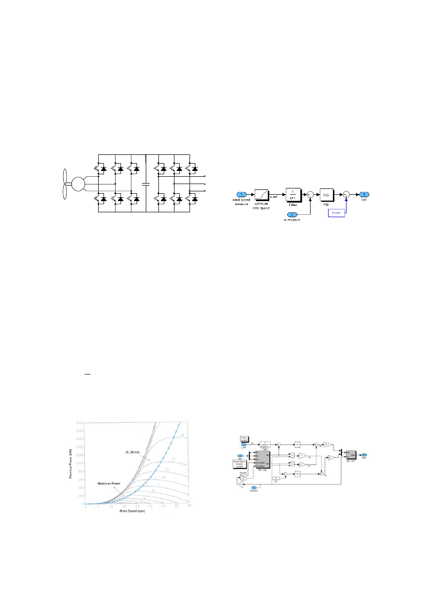
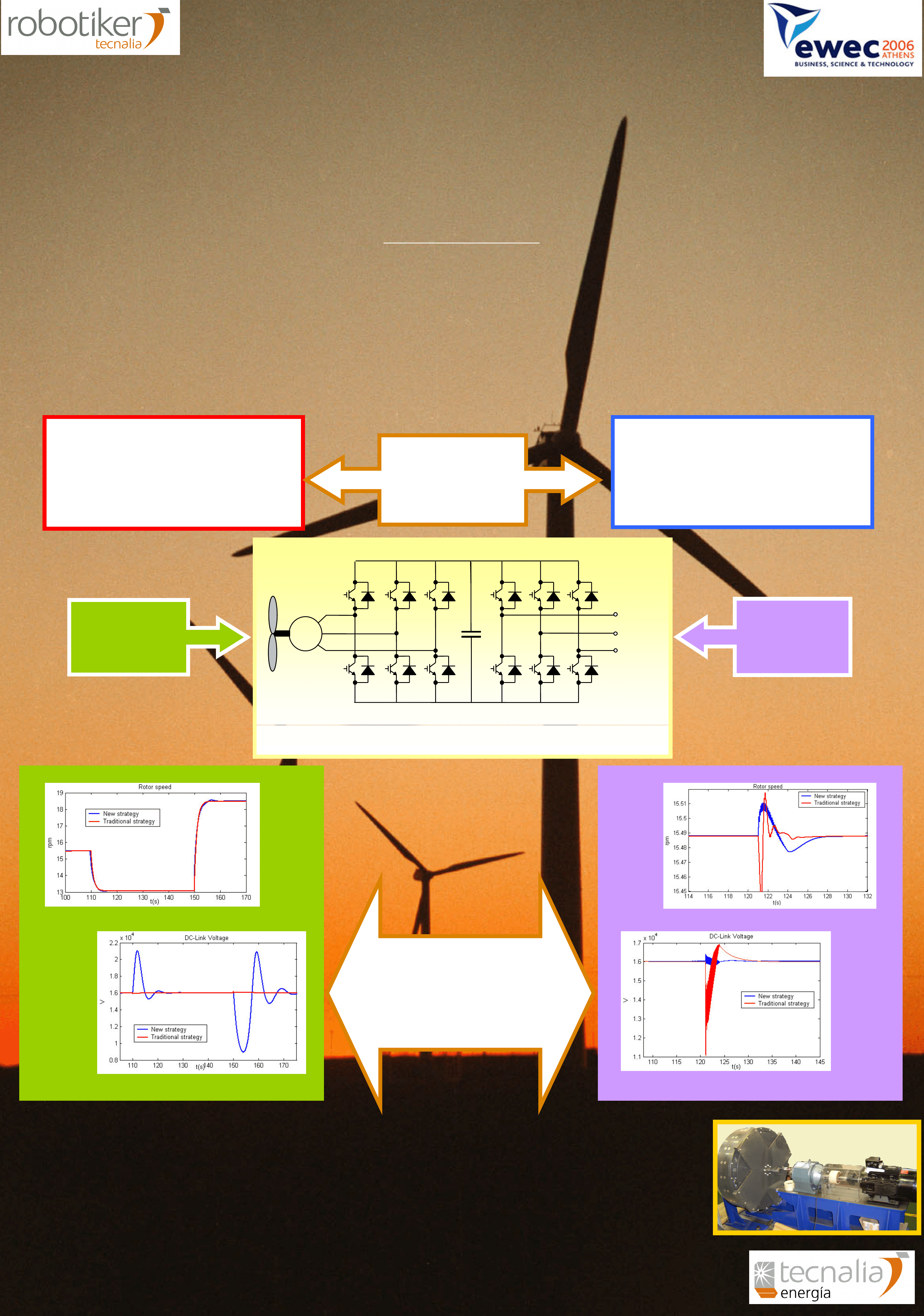
Fig.1: Configuration of the electrical power
generation system.
The system configuration is the same in both control
strategies. The turbine supplies the mechanical torque
to the generator depending on the wind speed and the
rotor speed. The generator is decoupled from the grid
by means of a DC-link.
Both strategies work with the same controllers, but
they are exchanged between generator side and grid
side converter. We will therefore, explain the control
and after, analyse how it is applied to each strategy.
2.2 Aerodynamics
The mechanical input power at the generator shaft
can be obtained as:
)
(
2
1
3
λ
ρ
Cp
AV
Pm
=
(1)
For a given wind turbine, the maximum power
depends on the wind speed and the power coefficient,
which is function of the tip speed ratio
λ and the
aerodynamic design.
Fig.2: Electrical power vs. rotor speed for several
wind speeds.
For a given Cp(
λ) [7], power curves can be plotted as
a function of the rotor speed for different values of
the wind speed, as shown in Fig. 2. From this, it
follows that for each wind speed, there is an optimal
rotor speed for extracting the maximum power.
2.3 Power Control
In this work, we base the power control on the rotor
speed control. The speed control loop in Fig.3,
assures that the wind turbine achieves the optimal
speed reference. This control consists of a PID
controller that, depending on the rotor speed error,
generates the reference of the generator current (1.
strategy) or grid current (2. strategy) that is to be
achieved in the generator side (1) or grid side (2)
converter.
Fig.3: Rotor speed control loop.
For each wind speed, electrical power and rotor speed
are linked as shown in Fig. 2. The optimum speed is
the one that makes the turbine work in the peak of the
curve. When the turbine is in the ascending part of
the curve, we demand more speed to the control, the
current reference falls and so does the output power
(electrical) with regard to the input power
(mechanical). Hence, the turbine speeds up until
input and output power are equal. When the turbine is
in the descending part, rotor speed reference falls,
increasing current reference and consequently output
power. In this case, the turbine decelerates. The
difference between mechanical and electrical power
causes oscillations in the rotor speed.
Synchronous generator model and internal switching
control of each converter is realised in dq coordinates
[13], [8]. A rotating reference system fixed to the
rotor has been used [16]. According to this reference
system, and the adopted sign criterion in the Park
transformation, the output current reference of the
rotor speed control loop, will be the id reference. Iq
reference will be set to 0 in this paper because we do
not do reactive control.
Fig.4: Generator side converter (1)/ Grid side
converter (2) control in dq coordinates.
With this control, we obtain the rotor speed reference
from the measured wind speed. It is necessary to
filter this speed since its high frequency components
C
PMSG
To grid
European Wind Energy Conference & Exhibition. February-March 2006, Athens.
3
do not supply energy but are an undesirable noise
source for the controller. The wind speed
measurement is not usually reliable, thus the
additional use of a maximum power point tracking
algorithm [14] is convenient. In case of wind speed
measurement error, this algorithm can take the rotor
to the real optimal speed which extracts the
maximum power.
2.4 DC-Link Control
In the traditional control strategy, the grid side
converter obtains the desired power factor, and
maintains the DC voltage to a previously fixed value.
The control is shown in Fig.5. This is the first
strategy of this work. The second strategy applies the
same control of Fig.5 to the generator side converter,
which will maintain the DC voltage to the desired
value.
Fig.5: DC_Link Control Loop. Grid side converter
(1)/ Generator side converter (2) control in dq
coordinates.
The DC voltage error is the input of a PI controller,
that obtains the id reference for the Grid (1) /
Generator (2) currents. In this control, iq reference is
also set to 0, but it can be used for controlling the
reactive power.
3 Simulation results
The aim of this work is to compare both control
strategies under external disturbances. For this
purpose, two kind of simulations have been carried
out: under wind speed variations, and under a voltage
dip. We analyse the behaviour of the rotor speed,
generated power, DC voltage, and grid currents. The
disturbances are introduced from the steady state.
Both models work in the same conditions for a
plausible comparison. The parameters of the
synchronous generator are set for 5 MW and 6,3kV.
The turbine is connected to a 10kV grid, through a
bus of 16kV, using a modulation index of 0,9.
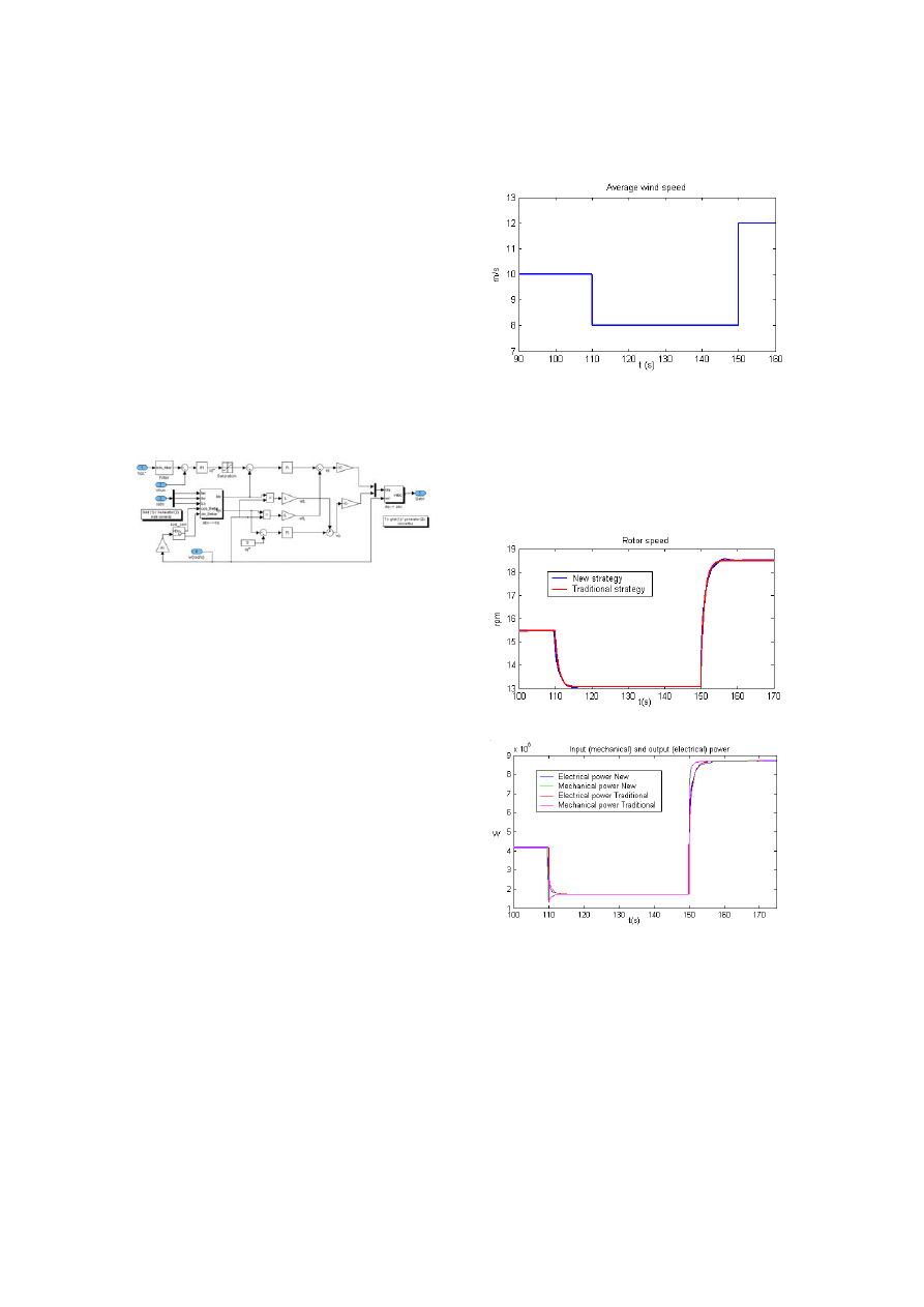
3.1 Wind Speed Variations
Simulation starts with an average wind speed of 10
m/s. Then, there is a step variation until 8 m/s. Once
it is stable, wind changes abruptly until 12 m/s. Fig.6.
None of the strategies has any problem in following
the optimum rotor speed control Fig.7(a). Therefore,
they rapidly extract the maximum power for each
wind speed Fig.7(b).
Fig.6: Simulated average wind speed.
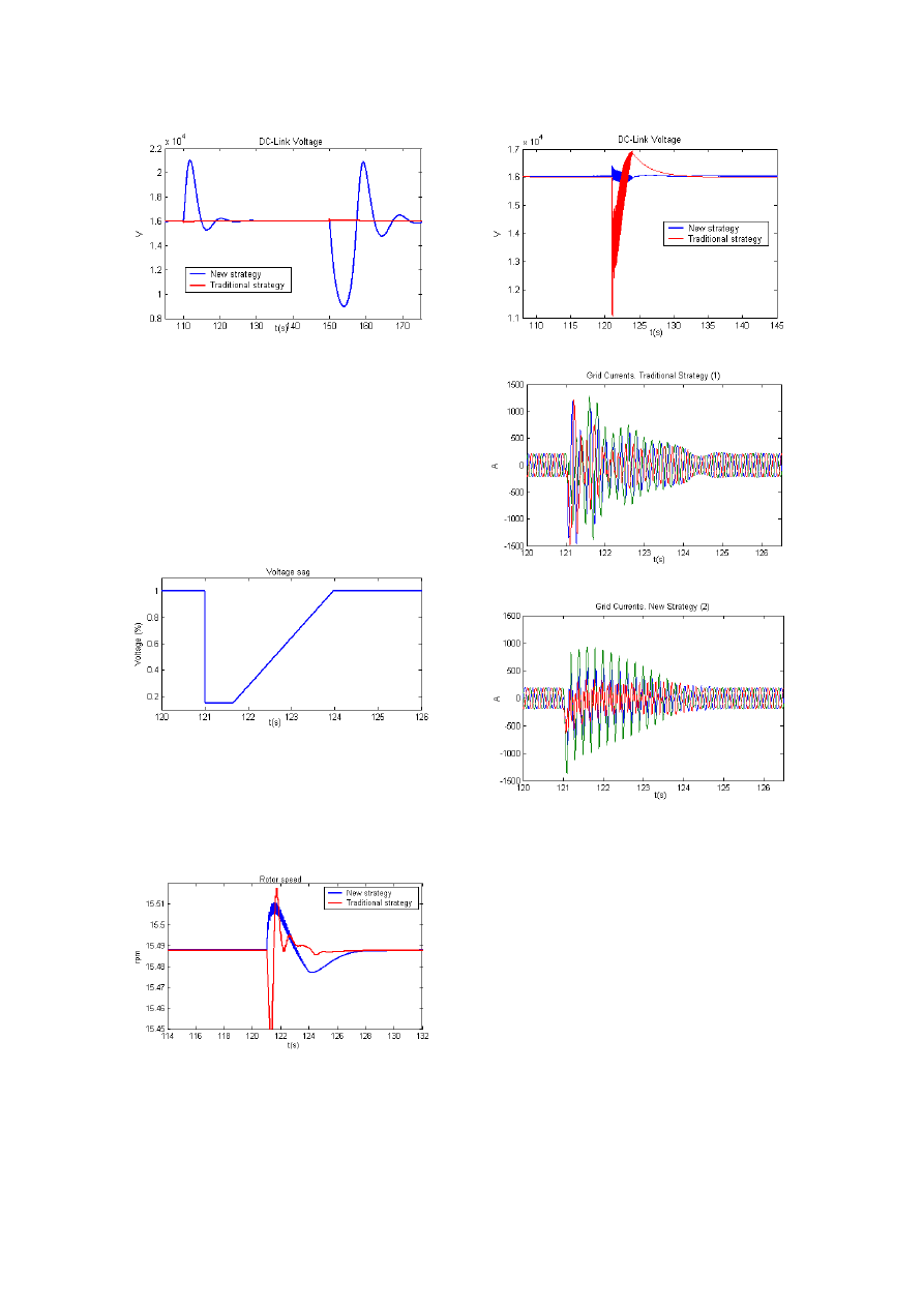
The only difference under this disturbance, is the
maintenance of the DC-link voltage. In the traditional
strategy (1), a little oscillation can hardly be seen.
However, as shown in Fig. 8, in the new strategy (2),
where the generator side converter maintains the DC-
link voltage, abrupt wind speed variations provoke
big oscillations in the DC voltage.
(a)
(b)
Fig.7: (a) Rotor speed, (b) input/output power
behaviour under wind speed variation.
European Wind Energy Conference & Exhibition. February-March 2006, Athens.
4
Fig.8: DC-link voltage under wind speed variations.
3.2 Voltage dip
It is important to analyse the machine behaviour
under voltage dips. New grid codes do not allow grid
disconnection, thus, wind turbines must support some
particular types of voltage dips, depending on the
country. Nowadays, there are different techniques to
reduce the impact of voltage dips, such as: Dynamic
Voltage Restorer (DVR) and crowbar, but until their
reaction, voltage dips affect the wind turbine.
Fig.9: Simulated voltage dip.
To compare both strategies, a single phase voltage
dip (with the same shape as defined on E.on grid
code) is introduced at second 121. Fig.9. In both
cases rotor speed suffers a light variation but it
stabilizes rapidly. Fig. 10 (a).
(a)
(b)
(c)
(d)
Fig.10: (a) Rotor speed, (b) DC-link voltage, (c) Grid
current in traditional strategy, (d) Grid current in new
strategy.
As shown in Fig.10 (b), under a voltage dip DC-link
voltage suffers a great oscillation in case of the
traditional strategy (1). The new strategy (2), where
the generator converter maintains the DC-link, hardly
notices the variation in the bus voltage.
Grid currents have a similar behaviour. However, in
the new strategy (2) they seem to have a slightly
smaller peak and a faster recovery.
4 Conclusions
Different simulations have been carried out for both
control strategies. Results show that in normal
conditions both have a similar performance, and that
the behaviour of each control strategy depends on the

European Wind Energy Conference & Exhibition. February-March 2006, Athens.
5
kind of disturbance. We have proved that the
converter closest to the disturbance has real problems
in maintaining a constant DC voltage. When there is
a wind speed variation, the best strategy is to control
the bus through the grid-side converter. Under
voltage dips, it is better to make the control of the DC
voltage with the generator-side converter.
In conclusion, both strategies have advantages and
disadvantages. Under wind speed variations, there are
other buffer components (blades, pitch control,
generator) between the wind and the power converter.
Whereas under grid voltage dips, there is nothing to
smooth over the disturbance and it is transmitted
directly to the converter. Therefore, it could be better
to control the bus with the generator-side converter.
The present work is mainly based on simulation.
Future objective is the experimental validation of
these results using a small-scale test bench with a 15
kW permanent magnet generator.
5 Acknoledgements
This work has been developed with the support of the
Education and Science Ministry of Spain under the
programme “Torres Quevedo” for young researchers.
6 References
[1] H. Sharma, T. Pryor, S. Islam, “Effect of pitch
control and power conditioning on power quality
of variable speed wind turbine generators,”
AUPEC 2001, 23-26 September 2001, Perth,
Australia, pp 95-100.
[2] H. Slootweg, E. de Vries, “Wind Turbines: Fixed
vs. Variable speed,” Renewable Energy World,
Feb. 2003.
[3] D.S. Zinger, E. Muljadi, “Annualized Wind
Energy Improvement Using Variable Speeds,”
IEEE Trans. on Industry Applications, Vol. 33,
nº6, Nov/Dec 1997, pp. 1444-1447.
[4] T. Zouaghi, “Variable Speed Drive modelling of
Wind Turbine Permanent Magnet Synchronous
Generator,” ICREP’04 International Conference
on Renewable Energy and Power Quality,
Barcelona, Spain, 2004.
[5] J. Marques, H. Pinheiro, H. A. Gründling, J. R.
Pinheiro and H. L. Hey, “A survey on variable
speed wind turbine system,” Congresso Brasileiro
de Eletrônica de Potência (COBEP), Fortaleza,
CE.
[6] Z. Chen, E. Spooner, “Grid interface options for
variable speed, permanent-magnet generators,”
IEEE Proc.-Electro. Power Appl., Vol. 145, Nº 4,
July 1998.
[7] Rodríguez Amenedo J.L, Burgos Díaz J.C,
Arnalte Gómez S, “Sistemas eólicos de
producción de energía eléctrica,” Ed. Rueda,
2003.
[8] M. Malinowski, S. Bernet, “Simple Control
Scheme of 3level PWM Converter connecting
wind turbine with grid,” Nordic Wind Power
Conference (Chalmers University of
Technology), 1-2 March, 2004.
[9]
D.C. Aliprantis, S.A. Papathanassiou, M.P.
Papadopoulos, A.G.Kaladas, “Modeling and
control of a variable-speed wind turbine equipped
with permanent magnet synchronous generator,”
Proc. Of ICEM/2000, Vol.3, pp.558-562.
[10]
A. Haniotis, S. Papathanassiou, A. Kladas,
M. Papadopoulus, “Control issues of a Permanent
Magnet Generator variable-speed Wind Turbine,”
Journal on Wind Engineering, Vol. 26, no 6, pp.
371-381, 2002.
[11] Hao, S. Hunter, G. Ramsden, V. Patterson, D.,
“Control system design for a 20 kW wind turbine
generator with a boost converter and battery bank
load,” Power Electronics Specialists Conference,
2001. PESC. 2001 IEEE 32nd Annual , Volume:
4 , 2001,pp: 2203 –2206.
[12] Schiemenz, I.; Stiebler, M., “Control of a
permanent magnet synchronous generator used in
a variable speed wind energy system,” Electric
Machines and Drives Conference, 2000. IEMDC
2001. IEEE International, 2001,pp 872 –877.
[13] B. Kwon, J. Youm, “A Line-Voltage-Sensorless
Synchronous Rectifier,” IEEE Transactions on
Power Electronics, vol. 14, nº. 5, pp. 966-972,
Sep. 1999.
[14] R. J. Spiegel, “Assessment of a wind turbine
intelligent controller for enhanced energy
production and pollution reduction,” Wind
Engineering Vol.25, No.1, pp. 23-32, 2001.
[15] Newman MJ, Holmes DG, Nielsen JG,
Blaabjerg F, “A dynamic voltage restorer (DVR)
with selective harmonic compensation at medium
voltage level,” IEEE Trans. on Industry
Applications, Vol. 41, nº6, Nov/Dec 2005, pp.
1744-1753.
[16] CHEE-MUN ONG "Dynamic Simulation of
Electric Machines Using MATLAB/Simulink"
Editorial "Prentice Hall", 1998.
!
" # $ %
!
" # $ %
!
" # $ %
!
" # $ %
&&&&
'
! (
'
! (
'
! (
'
! (
)
* $+ $
, - -
!
! $+ $ ! * + +
.! + - . $$ .! $
$
,$./ $
$ !
* !/
!
0
"
+ * $+ !
$
* !/ ,$./ $
1 ./ $
2
!/ . $-
$ 3 !/ 3
" *
$ ! $ ! -
$ 3
. $- !
* !/
$(
/
4 .! -
3 !/
" "
!
! +, + 33
$! . $!
! !
3 .(5! 5 .(
5 $( 3
. $- !
3
+ . $$ .! + +
.! + - * $+ !
$
+ ! $ , !/
$ !
+ . $- !
. $!
!/
.! 1 $ ! . ! 2
$+ !/
!/
$ ! + " *
*/
!/
+
+ . $- !
!
!/
$( - !
*
!/ " *
3 .!
$ !/
" "
*
-
!/ . $!
3 $.! $ 3 ./ . $- !
!/ !
$ !
+ . $- !
*
! !/
$( - !
$+ !/
+
+ . $- !
*
. $!
!/
.! 1 $ ! . ! 2
!/ ! $ ! -
$ ,
+ $+ . 1" + , 1 $
3
1 ! $
+ $
6 ! 7 1
$( 1 +
/
/ -
3
!/ ! !
0 1 $ + $+
"! * $+ "
+ - ! $ $+
+ + !
$.
33
$.
$
!
"
+ ! .( $
" *
$ ! +
- !
$+
+ .
$!
$ ,
+
8 $ $ 1 . $+ ! $
!/ / -
1 " 3 1 $.
8
/
/ -
3
./ . $!
! !
, + " $+
$ !/
( $+
3
+ !
$.
8
/
. $- !
.
! !
!/
+ !
$.
/
"
1
$
1 $! $ $
. $ ! $!
- !
/ $ !/
* $+ "
+
- ! $ !/
! ! !
,
! . $!
!/
!/
/ !/
+5
+ . $- !
$+
- !
+ "
!
!!
! 1 ( !/ . $!
3 !/
- !
* !/ !/
$ ! 5 + . $- !
C
PMSG
To grid
TRADITIONAL STRATEGY
The grid side converter maintains the DC
voltage, and the generator side converter
controls the rotor speed, and thus the
power, by means of the generator
current.
NEW STRATEGY
T
VOLTAGE
DIP
CONTROL
STRATEGIES
1
/ -
$ * $+
1
/ -
$ * $+
1
/ -
$ * $+
1
/ -
$ * $+ "
+
"
+
"
+
"
+
! .( $
! .( $
! .( $
! .( $
33
$.
$ !/ 1 $! $ $.
3
33
$.
$ !/ 1 $! $ $.
3
33
$.
$ !/ 1 $! $ $.
3
33
$.
$ !/ 1 $! $ $.
3
!/
!/
!/
!/
5555 $(
!
$(
!
$(
!
$(
!
/ . $- !
.
! ! !/
/ . $- !
.
! ! !/
/ . $- !
.
! ! !/
/ . $- !
.
! ! !/
+ !
$. /
"
1
$
+ !
$. /
"
1
$
+ !
$. /
"
1
$
+ !
$. /
"
1
$
1 $! $ $ . $ ! $!
- !
1 $! $ $ . $ ! $!
- !
1 $! $ $ . $ ! $!
- !
1 $! $ $ . $ ! $!
- !
CONCLUSIONS:
8
0 "
1 $!
- + ! $
3
!/
!
$
1 5
.
!
!
$./ * !/ 9 :
(
" 1 $ $!
1 $ !
$ !
8
!
!
; 6
*
"
+
$$ - ! -
$ !
FUTURE WORK:
.!
- $
$+
$ * !/ ; 6
,$./ $
.!
- $
$+
$ * !/ ; 6
,$./ $
.!
- $
$+
$ * !/ ; 6
,$./ $
.!
- $
$+
$ * !/ ; 6
,$./ $
$ !
$+
; *
$- !
$ !
$+
; *
$- !
$ !
$+
; *
$- !
$ !
$+
; *
$- !
WIND
VARIATION
Wyszukiwarka
Podobne podstrony:
[2006] Analysis of a Novel Transverse Flux Generator in direct driven wind turbine
Antigone Analysis of Greek Ideals in the Play
Analysis of Police Corruption In Depth Analysis of the Pro
Chizzola GC analysis of essential oils in the rumen fluid after incubation of Thuja orientalis tw
Quantitative dilatometric analysis of intercritical annealing in a low silicon TRIP steel
Solid Phase Microextraction Analyses of Flavor Compounds in
Chizzola GC analysis of essential oils in the rumen fluid after incubation of Thuja orientalis tw
Analysis of nonvolatile species in a complex matrix by heads
An analysis of energy efficiency in the production of oilseed crops
An agro economic analysis of willow cultivation in Poland 2006
Control Issues Of A Permanent Magnet Generator Variable Speed Wind Turbine
Separation Control Of High Angle Of Attack Airfoil For Vertical Axis Wind Turbines
Development Of A Single Phase Inverter For Small Wind Turbine
Boost Converter Design For 20Kw Wind Turbine Generator
Childhood lead exposure in France benefit estimation and partial cost benefit analysis of lead hazar
interactive art vs social interactions analysis of interactive art strategies in the light of erving
Causes and control of filamentous growth in aerobic granular sludge sequencing batch reactors
więcej podobnych podstron