W
e’ll now get into the fabrication
of the permanent magnet alter-
nator, which is unique in that it will
generate power at about 150 rpm, or
the equivalent of a six- to seven-mile-
per-hour wind. It consists of two mag-
net rotors, a stator, and some enameled
winding wire. There’s also a winding
process and a resin-casting procedure
described in detail.
A Little Alternator Theory
The reason we build our alternators
from scratch is that there are no com-
mercial alternators available that are
acceptable for use in a wind turbine
application. Vehicle alternators need
to spin very fast—1,000 revolutions
per minute and greater—before they
start making power, and we need to
start making power at about 150 rpm
and be at maximum output by 400 to
500 rpm. Car alternators also have
inadequate bearings, and they require
somewhere between 15 and 50 watts to
excite their own field. In short, they are
a poor choice for a wind turbine. Wind
enthusiasts want a machine that will
start spinning freely in the slightest
breeze, and this homebuilt alternator
does exactly that.
The wind speed in which a turbine
starts rotating is called the start-up
speed. This alternator will turn easily
below five mph, which is better than
almost any machine you could buy. In
very low winds, it will sit there turn-
ing, ready to make power, as soon as
the wind is ready. The speed at which
the alternator starts charging a battery
bank is called the cut-in speed. The
voltage is directly related to the rpm.
As the wind speed increases, so do
the rpm, and cut-in happens when the
alternator voltage gets greater than
the battery bank voltage. At this point
the battery is charging, which happens
at about 150 rpm in winds between six
and seven mph.
A permanent magnet alternator con-
verts the mechanical energy from the
rotating blades into electrical energy
by passing alternating magnetic poles
past coils of wire. The spacing of the
magnets and the size of the coils are
important to the design. The voltage
produced is directly related to the fol-
lowing: the strength of the magnetic
field, the number of windings in the
coils, and the rpm. The design can be
modified for use with 12V, 24V, and
48V power systems by simply using
different sized wire and changing the
number of windings.
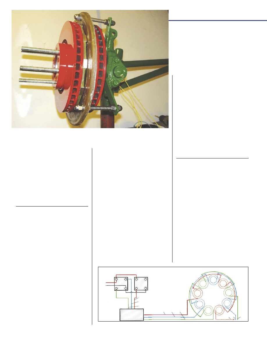
This alternator is wired in three-
phase star configuration, which gives
significant advantages in power output
and less vibration than single phase.
The output is alternating current (AC)
on three wires. This is sent through rec-
tifiers mounted on a big heat sink. They
convert the “wild AC” (called wild be-
cause it varies in voltage and frequency
with the shaft rpm) into direct current
(DC) for battery charging.
Building the Magnet Rotors
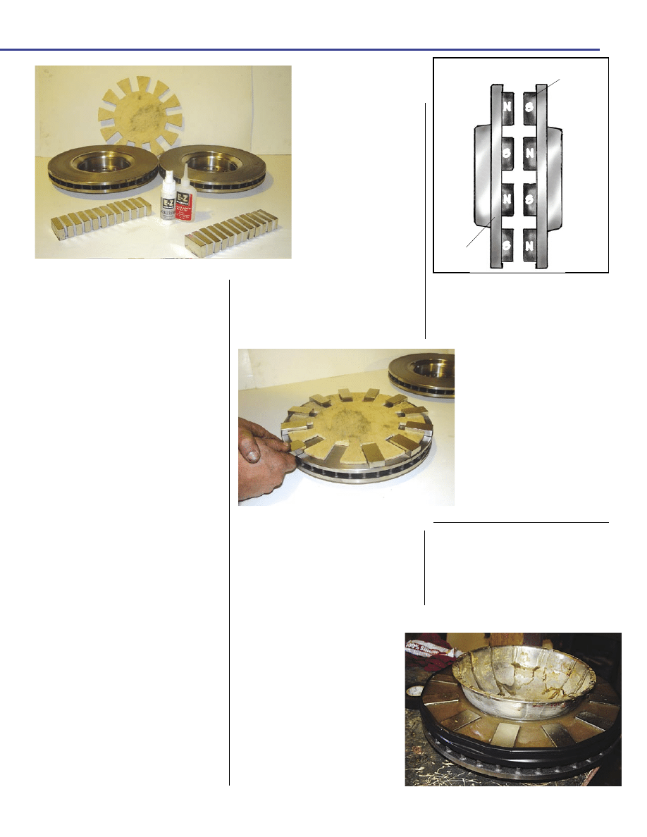
The 24 magnets we used in this
design (see photo 8) are N-35 grade
neodymium-iron-boron (NdFeB)
blocks measuring 2"
X
1"
X
1
/
2
" (see
www.otherpower.com for ordering
information). They are the most ex-
pensive component in the machine,
making up about half the total cost.
Their tremendous power and small size
are what make this alternator design
even possible. A word of warning:
Use extreme caution when handling
these magnets, and don’t let children
toy with them. They can jump to each
other (or to any ferrous metal) from a
surprising distance, and will shatter
if this occurs. If your fingers are in
the way, you’ll suffer a painful blood
blister or possibly even a fracture. After
the magnet rotors are assembled, the
combined force of 24 magnets and
PHOTOS SUPPLIED BY AUTHORS
ST
AFF ILLUSTRA
TIONS
1
2
3
1
2
3
1
2
3
X
Y
Z
3-P
HASE
O
UTPUT
F
ULL
-W
AVE
B
RIDGE
R
ECTIFIERS
X
Z
Y
W
IRING
D
IAGRAM
DC
O
UTPUT
+
+
_
_
AC
AC
AC
AC
S
TATOR
A B
C
6
www.
B
ACK
H
OME
M
AGAZINE
.
COM
steel would be enough to crush your
hand to a bloody pulp if you acciden-
tally got it between the rotors.
The brake disc rotors need to be
12" in diameter so the magnets will
all fit. Used brake rotors are usually
thrown away, and they will work fine
for this project. The thick steel behind
the magnets is actually an integral part
of this design—it completes magnetic
circuit, which substantially increases
the magnetic flux through the coils.
We first face each brake disc rotor by
turning it on a metal lathe. This gives
a clean, smooth, flat surface on which
to mount the magnets and also lets us
leave a
1
/
16
" lip around the rim to make
aligning the magnets easier and to help
keep them from flying off the discs
from centrifugal force. You might need
to drill a new set of five
1
/
2
" diameter
holes around the center of each rotor
in between the existing holes if the old
ones are so large in diameter that you
think the rotors will wobble or if they
came off another type of car and the
holes don’t match.
We built a plywood magnet align-
ment jig (see photo 9) to aid in placing
the magnets, as they should be spaced
perfectly. The polarity of the magnets
must alternate N-S-N-S as you go
around each rotor—opposite magnetic
poles attract, and you want each magnet
on each rotor to be intensely attracting
its opposite on the other rotor. Check
each magnet before placement—it
should repel its neighbor when held
over it, and then be mounted just the
way it’s sitting in your hand.
After all of the magnets are in place,
check each rotor again by passing a
handheld magnet over it. It should al-
ternately repel and attract as it’s moved
around the rotor. Once
you are positive that the
magnets are placed cor-
rectly, hit the bottom of
each one with a squirt
of thin cyanoacrylate
superglue and a squirt
of glue accelerator to
ensure they won’t move
during casting, and remove the magnet
placement jig.
The two magnet rotors should also
be perfectly aligned with each other,
with an attracting magnet exactly op-
posite it on the other rotor. We ensure
through attraction, it would shatter the
magnets and they’d be nearly impos-
sible to separate again. A magnet
rotor will also grab a wrench or
knife out of your hand from a
distance, so store the rotors at a
safe distance until you’re ready
for casting.
We usually cast the stator
and magnet rotors in one opera-
tion. For molds to hold the resin
around the magnet rotors, we use
stainless steel mixing bowls in
the centers and duct tape around
the rims (see photo 10).
Building the Stator
The first step in building the stator
is to wind the nine coils. We built a
simple coil-winding jig (see photo 11)
with an arm and handle that makes
the process easy. The tapered insert
ensures that the coils come out in the
proper, tapered toroid shape and size.
The magnet wire is specially designed
this by stacking both rotors up, facing
each other and lining up the holes
through which the studs will go. We
can then mark the side of the rotor so
that we’re sure the magnets on each
rotor will be perfectly aligned with
one another. Once assembled, if
we have a N pole on one rotor, we
must have a S pole on the other
facing it directly.
After the magnets are placed
and tacked down, set the magnet
rotors aside in a safe place. If they
should accidentally crash together
Photo 8: Magnet rotor
materials include a
plywood jig, two brake
rotors, 24 magnets, and
cyanoacrylate glue.
Photo 9: Magnet placement is aided by
the jig.
Attracting magnets must face each other
exactly on the rotor.
M
AGNETS
B
RAKE
R
OTORS
N
N
N
N
S
S
S
S
M
AGNET
R
OTORS
7
R
EPRINTED
FROM
B
ACK
H
OME
M
AGAZINE
Photo 10: Molding the magnet
rotors requires a stainless steel
mixing bowl at the center and
some duct tape around he edge
to hold the resin.
Wyszukiwarka
Podobne podstrony:
CEI 61400 22 Wind turbine generator systems Required Design Documentation
[2006] Application of Magnetic Energy Recovery Switch (MERS) to Improve Output Power of Wind Turbine
20060028025 Wind Turbine Generator System
(WinD Power) Dynamic Modeling of Ge 1 5 And 3 6 Wind Turbine Generator {}[2003}
IEC 61400 11 Wind turbine generator systems en
20050253396 Variable Speed Wind Turbine Generator
[US 2006] D517986 Wind turbine and rotor blade of a wind turbine
CEI 61400 22 Wind turbine generator systems Required Design Documentation
Boost Converter Design For 20Kw Wind Turbine Generator
20060028025 Wind Turbine Generator System
DIN 61400 21 (2002) [Wind turbine generator systems] [Part 21 Measurement and assessment of power qu
eBook Wind Power Savonius Rotor Construction by Jozef A Kozlowski WInd Power
[Engineering] Electrical Power and Energy Systems 1999 21 Dynamics Of Diesel And Wind Turbine Gene
[US 2006] D517986 Wind turbine and rotor blade of a wind turbine
[2006] Application of Magnetic Energy Recovery Switch (MERS) to Improve Output Power of Wind Turbine
IEC 61400 11 (2002) [Wind turbine generator systems Acoustic noise measurement techniques] [WIND][5
więcej podobnych podstron