HYDRAULIC SYSTEM
YARDMASTER®
HR45-25, HR45-27, HR45-31, HR45-40S,
HR45-36L, HR45-40LS, HR45-45LSX,
HR45H [A227]
PART NO. 1470232
1900 SRM 783

SAFETY PRECAUTIONS
MAINTENANCE AND REPAIR
• When lifting parts or assemblies, make sure all slings, chains, or cables are correctly
fastened, and that the load being lifted is balanced. Make sure the crane, cables, and
chains have the capacity to support the weight of the load.
• Do not lift heavy parts by hand, use a lifting mechanism.
• Wear safety glasses.
• DISCONNECT THE BATTERY CONNECTOR before doing any maintenance or repair
on electric lift trucks. Disconnect the battery ground cable on internal combustion lift
trucks.
• Always use correct blocks to prevent the unit from rolling or falling. See HOW TO PUT
THE LIFT TRUCK ON BLOCKS in the Operating Manual or the Periodic Mainte-
nance section.
• Keep the unit clean and the working area clean and orderly.
• Use the correct tools for the job.
• Keep the tools clean and in good condition.
• Always use HYSTER APPROVED parts when making repairs. Replacement parts
must meet or exceed the specifications of the original equipment manufacturer.
• Make sure all nuts, bolts, snap rings, and other fastening devices are removed before
using force to remove parts.
• Always fasten a DO NOT OPERATE tag to the controls of the unit when making repairs,
or if the unit needs repairs.
• Be sure to follow the WARNING and CAUTION notes in the instructions.
• Gasoline, Liquid Petroleum Gas (LPG), Compressed Natural Gas (CNG), and Diesel fuel
are flammable. Be sure to follow the necessary safety precautions when handling these
fuels and when working on these fuel systems.
• Batteries generate flammable gas when they are being charged. Keep fire and sparks
away from the area. Make sure the area is well ventilated.
NOTE:
The following symbols and words indicate safety information in this
manual:
WARNING
Indicates a condition that can cause immediate death or injury!
CAUTION
Indicates a condition that can cause property damage!

Hydraulic System YardMaster
®
Table of Contents
TABLE OF CONTENTS
Description .........................................................................................................................................................
Main Hydraulic Tank ....................................................................................................................................
Main Hydraulic Pump .......................................................................................................................................
Description .....................................................................................................................................................
Load Sensing Pressure ..................................................................................................................................
Main Pump Controller...................................................................................................................................
LS Servo.....................................................................................................................................................
LS Control Valve........................................................................................................................................
Power Servo ...............................................................................................................................................
Adjust .............................................................................................................................................................
Load Sensing Pressure LS1 ......................................................................................................................
Load Sensing Pressure LS2 ......................................................................................................................
Standby Pressure ......................................................................................................................................
Power Control Valve..................................................................................................................................
Main Control Valve ............................................................................................................................................
Description .....................................................................................................................................................
Adjustment.....................................................................................................................................................
Relief Pressures.........................................................................................................................................
Main .......................................................................................................................................................
Derricking Up........................................................................................................................................
Derricking Down ...................................................................................................................................
Telescoping Out .....................................................................................................................................
Telescoping In........................................................................................................................................
Spreader Supply....................................................................................................................................
Spreader Standby..................................................................................................................................
Steering Supply.....................................................................................................................................
Derricking Cylinder ..............................................................................................................................
Flow Control Settings ...............................................................................................................................
Derricking Down Speed ............................................................................................................................
Derricking Up Speed .................................................................................................................................
Telescoping Speeds ....................................................................................................................................
Steering ..............................................................................................................................................................
Description .....................................................................................................................................................
Adjust .............................................................................................................................................................
Pilot System .......................................................................................................................................................
Pilot Pump .....................................................................................................................................................
Telescoping Retract Control Valve............................................................................................................
Engine Radiator Fan Motor ......................................................................................................................
Adjust.....................................................................................................................................................
Manipulator Pressure Valve .....................................................................................................................
Description ............................................................................................................................................
Operation...............................................................................................................................................
Adjust.....................................................................................................................................................
Engine Accelerator System .......................................................................................................................
Adjust.....................................................................................................................................................
Joystick ......................................................................................................................................................
Hydraulic Cooling System .................................................................................................................................
Description .....................................................................................................................................................
Brake Oil Cooling System .................................................................................................................................
Description .....................................................................................................................................................
Adjust .............................................................................................................................................................
©2004 HYSTER COMPANY
i

Table of Contents
Hydraulic System YardMaster
®
TABLE OF CONTENTS (Continued)
100 Bar Relief Valve ..................................................................................................................................
Service Brakes....................................................................................................................................................
Description .....................................................................................................................................................
Parking Brake ....................................................................................................................................................
Description .....................................................................................................................................................
This section is for the following models:
HR45-25, HR45-27, HR45-31, HR45-40S, HR45-36L, HR45-40LS,
HR45-45LSX, HR45H [A227]
ii
1900 SRM 783
Description
Description
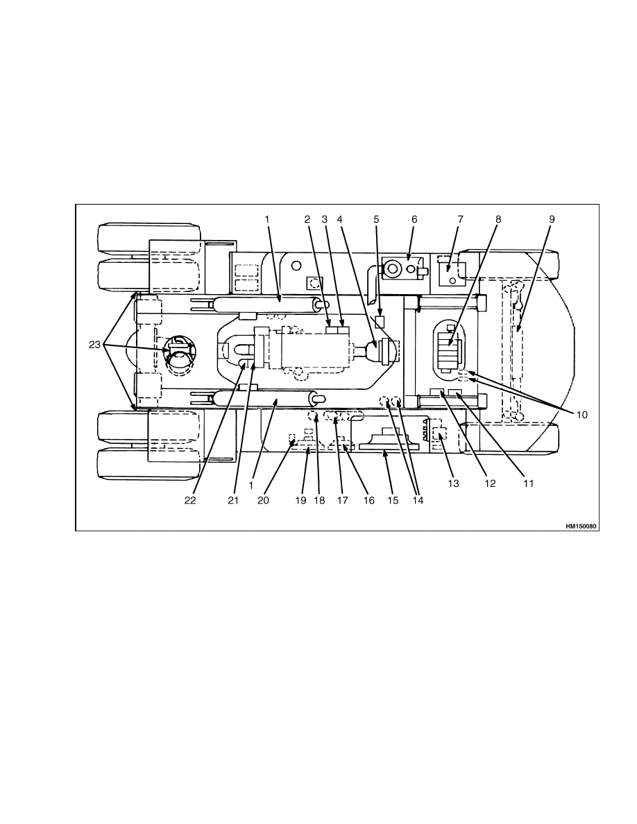
This section describes the hydraulic system at the
frame side of the Laden Yardmaster.
A location
overview of the hydraulic system components is
shown in Figure 1.
Related items for the hydraulic system can be found
in the following:
• Electrical System 2200 SRM 1065
• Diagrams 8000 SRM 784
• Boom 4500 SRM 787
• Extendable Container Attachment, PPM 5000
SRM 1063
NOTE: Information on the Elme spreaders can be
found in Extendable Container Attachment 5000
SRM 776.
1.
DERRICKING CYLINDER
2.
PILOT PUMP
3.
SERVICE BRAKE PUMP
4.
MAIN PUMP
5.
PARK BRAKE SOLENOID VALVE
6.
MAIN HYDRAULIC TANK
7.
BRAKE COOLING OIL TANK
8.
MAIN CONTROL VALVE
9.
STEERING CYLINDER
10. 170 & 210 bar (2466 & 3046 psi) LOAD SENSING
SWITCHES
11. BOOM AND SPREADER SUPPLY BLOCK
12. WINCH VALVE (OPTIONAL)
13. MANIPULATOR PRESSURE VALVE
14. BRAKE ACCUMULATOR
15. ENGINE RADIATOR
16. HYDRAULIC SYSTEM OIL COOLER
17. HYDRAULIC SYSTEM OIL FILTERS
18. BRAKE COOLING SYSTEM OIL FILTER
19. BRAKE SYSTEM OIL COOLER
20. BRAKE COOLING SOLENOID VALVE
21. HYDRAULIC COOLING SYSTEM PUMP
22. BRAKE COOLING SYSTEM PUMP
23. BRAKES
Figure 1. Hydraulic System Components Location
1
Main Hydraulic Pump
1900 SRM 783
MAIN HYDRAULIC TANK
The hydraulic tank is located at the RH side of the
frame. At the side of the truck, a sight glass indi-
cates the hydraulic oil level. When the running board
cover above the tank is open, the breather and the
general oil return are accessible. The breather also
serves as the fill plug. The general oil return bracket
incorporates the oil return screen, which is accessi-
ble after the bracket is removed.
Just in front of the cover is the suction shutoff, which
allows replacement of pump suction hoses without
having to empty the entire tank. Verify the suction
valve is open before starting the engine.
Main Hydraulic Pump
DESCRIPTION
The main hydraulic pump provides oil pressure to
the steering system, boom, and spreader functions.
All other hydraulic functions use separate oil pumps.
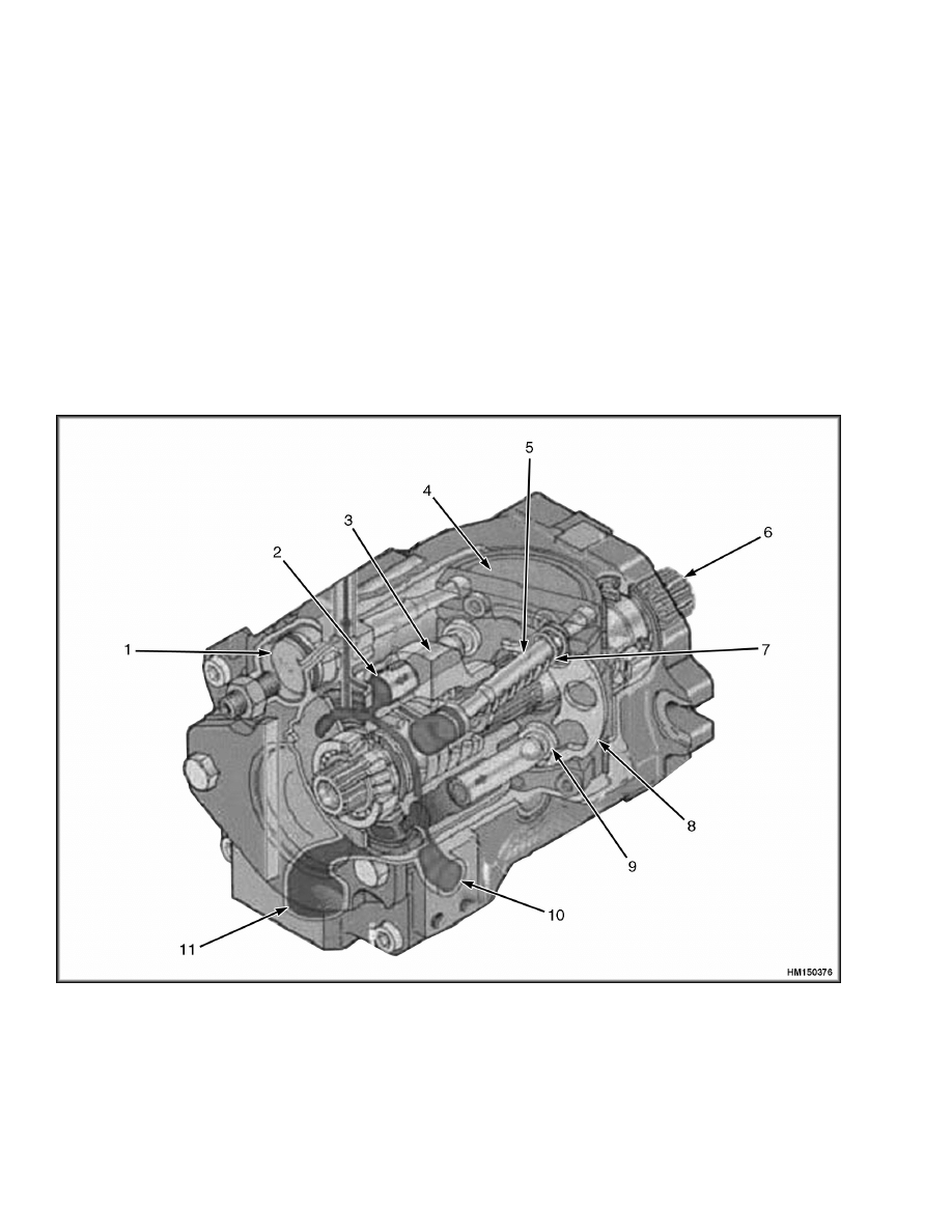
The main hydraulic pump is a variable displacement
pump with two identical sections. See Figure 2.
1.
LOAD SENSING SERVO
2.
PLUNGER
3.
PLUNGER HOUSING
4.
SWASH PLATE
5.
POWER SERVO
6.
PUMP SHAFT
7.
SPRING
8.
DISC
9.
JOINT
10. PRESSURE PORT
11. SUCTION PORT
Figure 2. Main Hydraulic Pump
2
1900 SRM 783
Main Hydraulic Pump
Figure 2 shows only one section of the pump.
Each section consists of a housing with nine pump
plungers.
The housing with the plungers rotate
and is driven by the pump shaft. The plungers are
connected with a disc by joints. The position of the
plunger in the housing depends on the position of
the disc.
The disc rotates in a cutaway of the swash plate.
When the swash plate is at an angle, the disc will
rotate at the same angle.
The joints in the disc
will follow the induced axial movement, forcing the
plungers in the housing to make the same stroke
at each revolution. When the swash plate is level,
the plungers will not make a stroke. The angle of
the swash plate determines the volume displaced by
the plungers which relates directly to pump supply
volume. See Main Pump Controller.
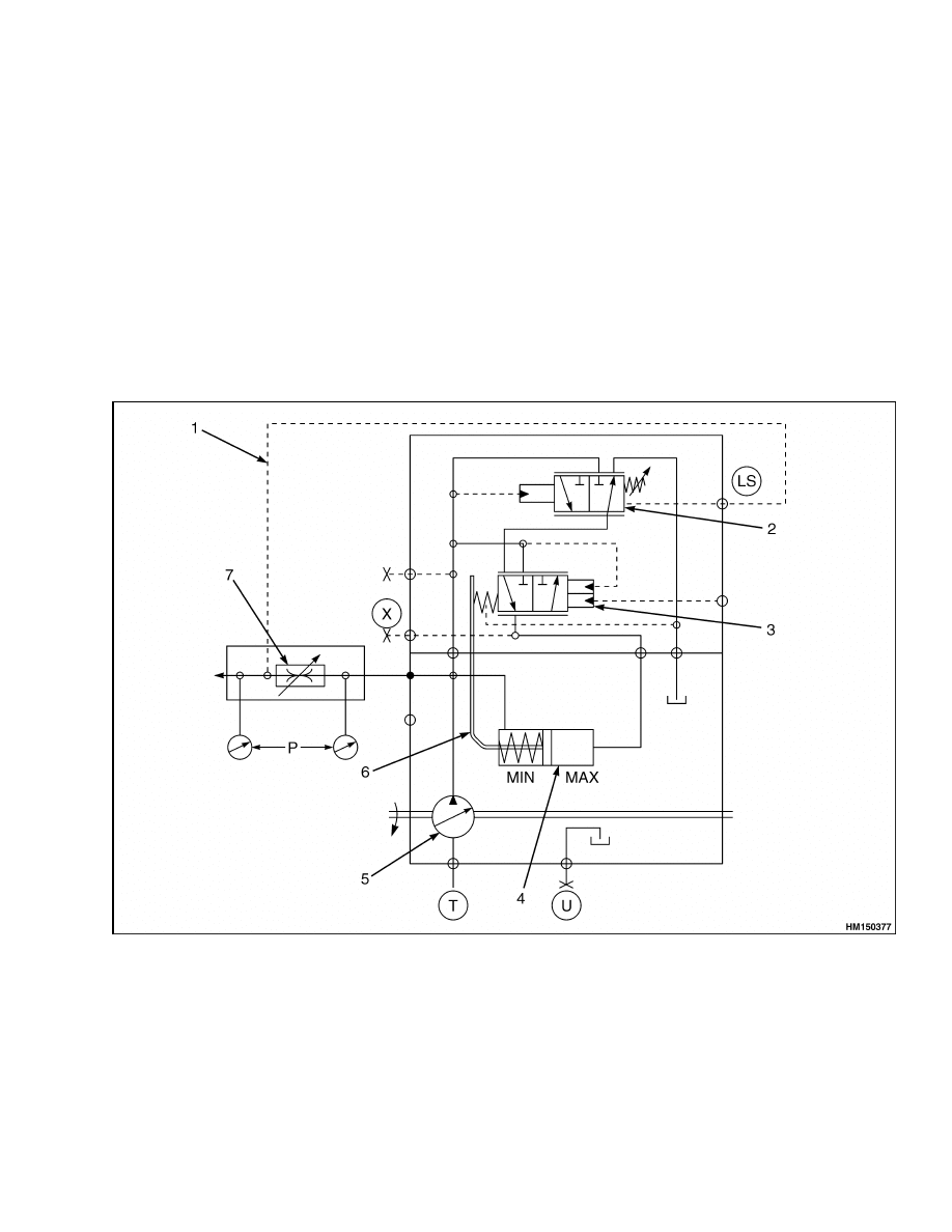
LOAD SENSING PRESSURE
Oil leaves the pump via a variable metering orifice
in the pump control valve. Independently of the flow,
the variable metering orifice causes a pressure drop
between 22 and 25 bar (319 and 363 psi). The vari-
able metering orifice is adjusted by regulators LS1
and LS2 on the pump control valve. This implies that
delivered pump oil pressure is always 22 bar (319 psi)
lower than the pressure at the pump plungers. See
Figure 3.
1.
LOAD SENSING LINE
2.
LS CONTROL VALVE
3.
POWER SERVO
4.
LS SERVO
5.
PUMP
6.
SWASH PLATE
7.
VARIABLE METERING ORIFICE
Figure 3. Main Pump Controller
3

Main Hydraulic Pump
1900 SRM 783
The pressure measured immediately after the meter-
ing orifice is called Load Sense (LS) Pressure. LS
pressure tends to get lower at increasing flow and
tends to get higher at decreasing flow. The absolute
LS pressure varies almost according to pump pres-
sure.
To properly detect variations in load sense pressure,
the LS pressure line is separately connected with the
LS controller. The LS pressure line and LS controller
are also connected with the priority valves in the
main control valve with the steering system. To ob-
tain one signal for both pump sections, the LS1 and
LS2 ports are interconnected at the main pump and
at the main control valve.
When flow demand increases, the initially higher LS
pressure will escape via the priority valves to the
function being operated. The resulting pressure drop
in the LS pressure line is signalled by the LS con-
troller in the pump control system.
MAIN PUMP CONTROLLER
The pump controller contains servos and the LS con-
trol valve, which manipulate the angle of the swash
plate. The pump controller consists of the bigger LS
servo, LS control valve and the smaller power servo.
When there is no oil pressure, the spring will move
the swash plate towards maximum supply. When
there is high oil pressure, the bigger LS servo will
overcome forces of both the spring and the smaller
power servo and moves the swash plate towards min-
imum supply.
The position of the swash plate is primarily deter-
mined by the pressure in the LS servo, which is reg-
ulated by the LS control valve.
LS Servo
The LS servo is directly connected with the swash
plate. The piston side of the LS servo receives pres-
sure from the LS control valve. The rod side is di-
rectly pressurized by pump pressure. Apart from a
spring that moves the LS servo towards maximum
supply, the pressure difference between the pump
and the LS control valve determines the position of
the LS servo.
LS Control Valve
The LS control valve controls pressure at the piston
side of the LS servo by comparing pump pressure
with load sense (LS) pressure. At higher pressure
differences, when LS pressure is relatively low, pres-
sure for the LS servo is drained to tank. The LS servo
will move the swash plate towards maximum supply.
At relatively higher LS pressures, when there is less
oil demand, the spool supplies pump pressure to the
LS servo, which will move the swash plate to mini-
mum supply.
The LS controller cannot be adjusted separately, but
its function relates to the pressure settings of LS1
and LS2. See Adjust.
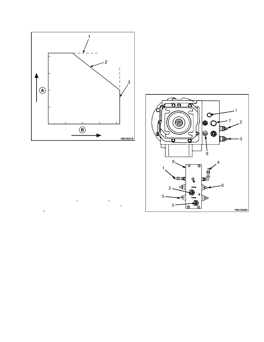
Power Servo
Maximum supply flow of the pump is 420 liter
(111 gal)per minute at 2350 rpm. This supply flow
would overload the engine at higher pressures.
When demanded oil flow and pressure represent
a higher engine power than the available engine
power, the power servo reduces supply flow by pres-
surizing the LS servo. See Figure 4.
The pressure at which the power servo starts pres-
surizing the LS servo depends on the absolute pump
pressure and the momentary force of the power
servo spring.
The momentary force of the power
servo spring depends on the position of the swash
plate (equal to pump supply).
The power servo
spring is less compressed at maximum pump supply,
allowing the power servo to be opened more easily.
At decreasing oil supply, it takes a higher pump pres-
sure until the power servo opens to pressurize the LS
servo. When pump supply volume has decreased to
a third of maximum supply, the power servo will no
longer open. This is because the maximum system
pressure has been reached, which is determined by
the main relief valve.
The power servos are adjusted regulators X1 and X2
for each of the pump sections. See Adjust.
To cover for low power at idle engine speeds or just
above, oil supply is reduced by the manipulator
valve. See Manipulator Pressure Valve.
4
1900 SRM 783
Main Hydraulic Pump
A. PRESSURE
B. FLOW
1.
MAIN RELIEF VALVE PRESSURE
2.
POWER REGULATION
3.
MAXIMUM SUPPLY
Figure 4. Power Regulation
ADJUST
NOTE: Adjustments must be made with engine
temperature 60 to 80 C (140 to 176 F) and with
hydraulic oil temperature between 45 to 65 C (113
to 149 F).The engine must be running at full speed,
spreader fitted, no load.
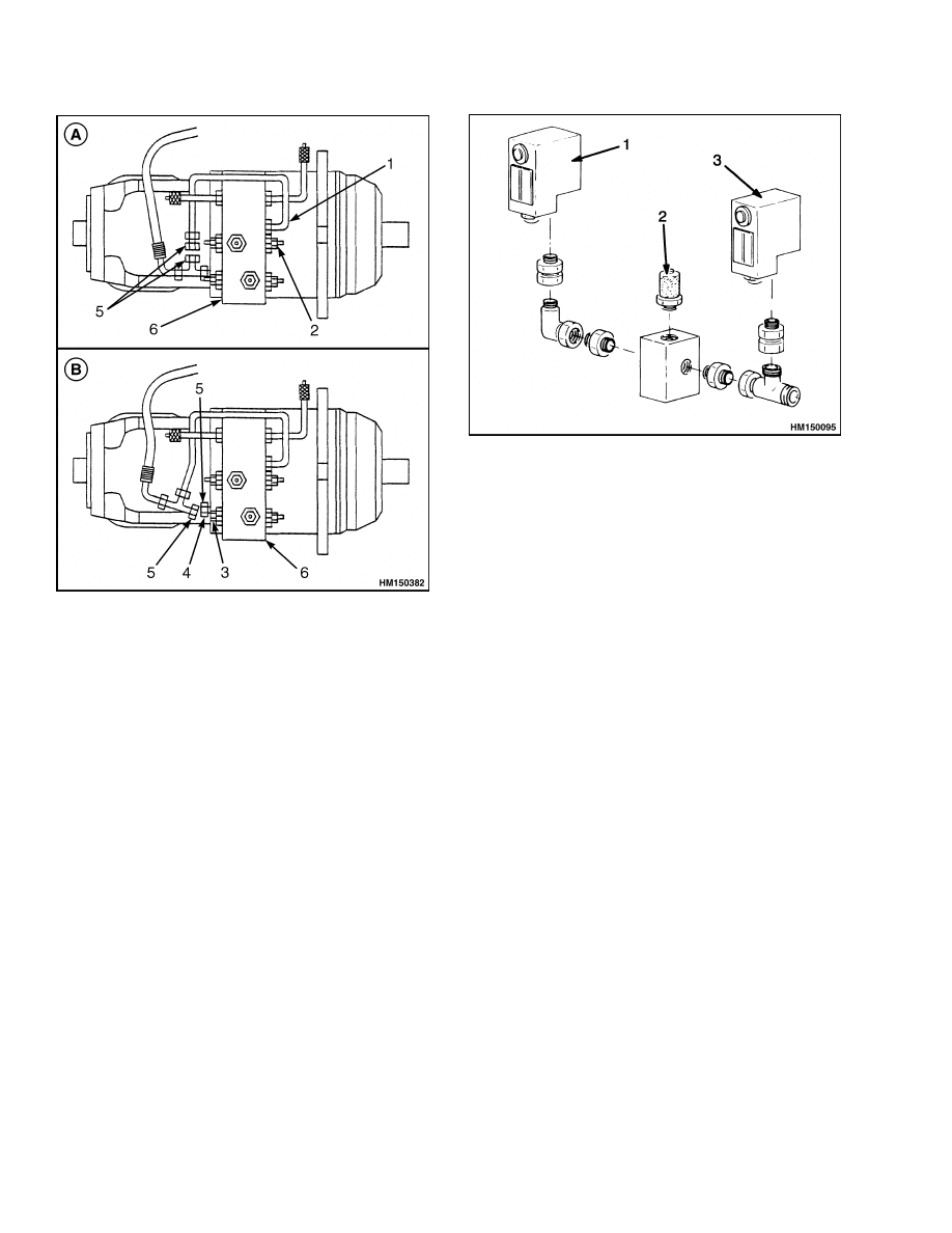
Load Sensing Pressure LS1
NOTE:
To set pressure at the load sense line, regula-
tors LS1 and LS2 have to be isolated, and pressures
have to be set independently. See Figure 5.
1.
Disconnect the LS2 connection from the pump
and plug the open connections. See Figure 6.
2.
Install a pressure gauge of 600 bar (8702 psi) at
port M on the main control valve. See Figure 8.
3.
Install a pressure gauge of 600 bar (8702 psi) at
the load sensing pressure line. See Figure 7.
4.
Run engine at 1200 rpm.
5.
Operate sideshift function left to right and adjust
pressure regulator LS1 between 22 to 25 bar (319
to 363 psi) during operation of the sideshift func-
tion.
6.
Remove the plugs and reconnect the LS2 load
sensing line.
1.
X1 TEST PORT
2.
X1 POWER REGULATOR
3.
X2 POWER REGULATOR
4.
X2 TEST PORT
5.
LS2 REGULATOR
6.
LS1 REGULATOR
7.
DUMMY
8.
LS2 PORT
9.
PUMP CONTROLLER
Figure 5. Pump Controller Adjustments
5
Main Hydraulic Pump
1900 SRM 783
A. LS1 PRESSURE SETTING
B. LS2 PRESSURE SETTING
1.
LS1 PORT
2.
LS1 REGULATOR
3.
LS2 REGULATOR
4.
LS2 PORT
5.
PLUG
6.
CONTROLLER
Figure 6. LS1 and LS2 Pressure Settings
Load Sensing Pressure LS2
Pressure setting for LS2 is similar for LS1. To set
LS2 pressure, isolate LS1 from the LS line. See De-
scription and Figure 6.
To avoid interference at the load sense controllers,
pressures at LS1 and LS2 may NOT be identical.
Maintain a difference of about 2 bar (29 psi). The
pump produces a noise when the difference in pres-
sure is too small.
1.
PRESSURE SWITCH 170 bar (2466 psi)
2.
LOAD SENSING PRESSURE SWITCH PLUG
3.
PRESSURE SWITCH 210 bar (3046 psi)
Figure 7. Load Sensing Pressure Switches
Standby Pressure
NOTE:
To verify the minimum available pressure,
measure the pump pressure at the main valve bank
at port M. See Figure 8.
1.
Run engine at idle with no functions operating.
NOTE:
Standby pressure must be 30 to 35 bar (435
to 508 psi).
2.
Adjust LS1 and LS2 accordingly.
Power Control Valve
1.
Install a pressure gauge of 600 bar (8702 psi) on
following points:
• Port M on the main control valve
• Pressure plugs X1 and X2 on the main pump
2.
At the main control valve, temporarily set the
pressure at 180 bar (2611 psi) at full throttle for
following relief valves:
• Boom derricking up relief valves B3 and B4
• The two main relief valves (at M and at port
P1)
6
1900 SRM 783
Main Control Valve
NOTE:
For a smooth transition to the power regulat-
ing mode, set X1 and X2 at a pressure difference of
about 3 bar (44 psi).
3.
Adjust power regulators X1 and X2 at full throt-
tle to 80 bar (1160 psi) ±10 bar (145 psi).
4.
Adjust the main relief valves to 420 bar (6092 psi)
and the derricking up relief valves to 350 bar
(5076 psi).
Main Control Valve
DESCRIPTION
The main control valve consists of six sections, which
are held together with tie-rods. The two outer sec-
tions serve as a hydraulic connection for the four in-
ner sections. Openings in the sections interconnect
with pump supply, load sense line, and tank return.
The steering priority valves, block hydraulic flow to
the four inner functions when load sense pressure at
the steering side is lower than load sense pressure at
the inner sections. See Figure 8 and Figure 9.
The RH outer, P1 section has a bolted-on steering
priority valve and an integrated main relief valve,
which is normally set to 420 bar (6092 psi).
The LH outer section has, in addition to the 420 bar
(6092 psi) main relief valve, a 220 bar (3191 psi)
steering relief valve, a steering priority valve and the
bolted-on 25 bar (363 psi) standby pressure valve for
the spreader.
The four inner sections are for the spreader, telescop-
ing, and derricking functions. Each inner section has
a spool that opens proportionally with pilot pressure
at the ZA and ZB ports. Flow rate of the spools is ad-
justed by reducing or extending the maximum spool
stroke with an adjustment bolt.
The location of the flow control valves is at the A side
of the main valve. Relief valves for A ports are lo-
cated at the A side of the valve. Relief valves for B
ports are located at the B side of the valve. For the
location of the various ports, see Figure 8 and Fig-
ure 9.
Control valve sections cannot be repaired, except for
replacing relief valves or exchanging seal kits. If the
control spool is being removed, the mounting bolts
must be secured with oil resistant Loctite
®
.
Table 1. Main Control Valve Torque Specifications
Item
Specification
Tie-rod nuts
100 ±10 N•m (74 ±7 lbf ft)
Tie-rod locknut
60 ±10 N•m (44 ±7 lbf ft)
Relief valves
85 ±10 N•m (63 ±7 lbf ft)
Flow valves
100 ±10 N•m (74 ±7 lbf ft)
Pilot ports
17 ±5 N•m (13 ±4 lbf ft)
Load sense plug
17 ±5 N•m (13 ±4 lbf ft)
7
Main Control Valve
1900 SRM 783
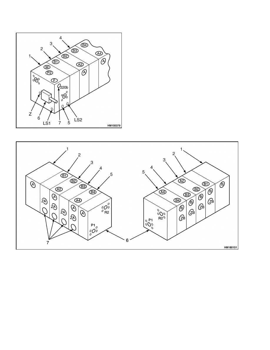
Figure 8. Main Control Valve Ports
Legend for Figure 8
1.
MAIN SECTION
2.
SPREADER SECTION
3.
TELESCOPING SECTION
4.
DERRICKING SECTION
5.
STEERING PRIORITY VALVE
6.
SPREADER STANDBY RELIEF VALVE
7.
STEERING RELIEF VALVE, P2
A PORT RELIEF VALVES
B1 PORT
P1 PORT
A2 PORT
B2 PORT
R2 PORT
A4 PORT
B3 PORT
ZA PILOT PORTS
B PORT RELIEF VALVES
B4 PORT
ZB PILOT PORTS
1.
STEERING/MAIN VALVE SECTION
2.
SPREADER VALVE SECTION
3.
TELESCOPING VALVE SECTION
4.
DERRICKING VALVE SECTION
5.
DERRICKING VALVE SECTION
6.
MAIN RELIEF VALVE SECTION
7.
FLOW CONTROL VALVES
Figure 9. Main Control Valve Ports, Alternate View
8

1900 SRM 783
Main Control Valve
ADJUSTMENT
NOTE: Adjustments must be made with engine
temperature 60 to 80 C (140 to 176 F) and with
hydraulic oil temperature between 45 to 65 C (113
to 149 F).The engine must be running at full speed,
spreader fitted, no load.
Relief Pressures
Main
1.
Attach a pressure gauge of 600 bar (8702 psi) at
port M. See Figure 8.
2.
Temporarily increase the pressure of the derrick-
ing up relief valves, B3 and B4, to over 420 bar
(6092 psi).
3.
Fully raise the boom and keep the joystick in der-
ricking position.
4.
Adjust the two main relief valves to 420 bar
(6092 psi) with the engine at full throttle.
5.
With the boom still raised, reset the derricking
up relief valves, B3 and B4, to 350 bar (5076 psi).
Derricking Up
1.
Attach a pressure gauge of 600 bar (8702 psi) at
port M.
2.
Fully raise the boom and keep the joystick in der-
ricking position.
3.
With the engine at full throttle, set the derricking
up relief valves, B3 and B4, to 350 bar (5076 psi).
Derricking Down
1.
Attach a pressure gauge of 600 bar (8702 psi) at
port M.
2.
Fully lower the boom and keep the joystick in
derricking down position.
3.
With the engine at full throttle, set the derricking
down relief valve A4 to 110 bar (1595 psi).
Telescoping Out
1.
Attach a pressure gauge of 600 bar (8702 psi) at
port M.
2.
Fully extend the boom and keep the joystick in
the extending position.
3.
With the engine at full throttle, set extension re-
lief valve A2 to 350 bar (5076 psi).
Telescoping In
1.
Attach a pressure gauge of 600 bar (8702 psi) at
port M.
2.
Fully retract the boom and keep the joystick in
retraction position.
3.
With the engine at full throttle, set retraction
relief valve B2 to 190 bar (2756 psi).
Spreader Supply
1.
Attach a pressure gauge of 600 bar (8702 psi) at
port M.
2.
Disconnect solenoids E16 and E17 at the
spreader control valve.
3.
Operate and hold the sideshift lever.
4.
With the engine at full throttle, set spreader sup-
ply relief valve B1 to 200 bar (2901 psi).
5.
Reconnect solenoids E16 and E17.
Spreader Standby
1.
Remove and plug the hose from port Z.
2.
Attach a pressure gauge at port Z.
3.
Remove the plug from the relief valve.
4.
Run the engine at elevated idle and set the
spreader standby relief valve to 25 bar (363 psi).
5.
Replace the plug, remove the gauge, and recon-
nect the hose to port Z.
Steering Supply
1.
Attach a pressure gauge of 600 bar (8702 psi) at
port M.
2.
Operate the steering wheel at full stroke.
3.
With the engine at full throttle, set steering sup-
ply relief valve P2 to 220 bar (3191 psi).
9

Steering
1900 SRM 783
Derricking Cylinder
Maximum occurring pressure at the derricking cylin-
der is set at the holding valve. See Boom 4500 SRM
787 for adjustment procedure.
For adjustment of the spreader functions see Ex-
tendable Container Attachment, PPM 5000
SRM 1063 and for boom functions see Boom 4500
SRM 787.
Flow Control Settings
Hydraulic oil flow is checked by measuring the time
required to complete a specific movement. To speed
up, increase flow by loosening the socket head screw
at the flow control valve. To slow down, restrict flow
by tightening the socket head screw.
Derricking Down Speed
Derricking down speed is set at the holding valves
on the derricking cylinders, if flow control valve A4
provides sufficient flow.
Establish the correct setting of the flow control valve
at A4 as follows:
NOTE:
Time required to fully lower the boom at full
throttle is 30 to 32 seconds.
1.
Measure actual derricking down speed.
2.
Adjust the holding valves as necessary.
See
Boom 4500 SRM 787.
3.
Tighten the flow control valve at A4 until derrick-
ing down speed is reduced.
4.
Release the socket head screw until flow restric-
tion is again influenced by the holding valves.
Derricking Up Speed
NOTE: First adjust derricking down speed before ad-
justing derricking up speed.
Derricking up speed is set by the flow control valves
at A3 and A4. The total resulting flow of ports B3 and
B4 determines the derricking up speed. Try to keep
the setting of B3 and B4 at an equal value by keep-
ing the socket head screws equally tightened. When
derricking up speed has to be reduced, tighten flow
control valve A3. Do not tighten A4, because this will
affect derricking down speed as well. Time to derrick
up completely at full throttle is 22 to 23 seconds.
Telescoping Speeds
Both telescoping retraction and extension speeds are
restricted by the flow control valve at A2. This im-
plies that a compromise must be found between both
speeds. The time required to fully extend the tele-
scoping cylinder is 28 to 30 seconds. The time re-
quired to fully retract is 25 to 28 seconds.
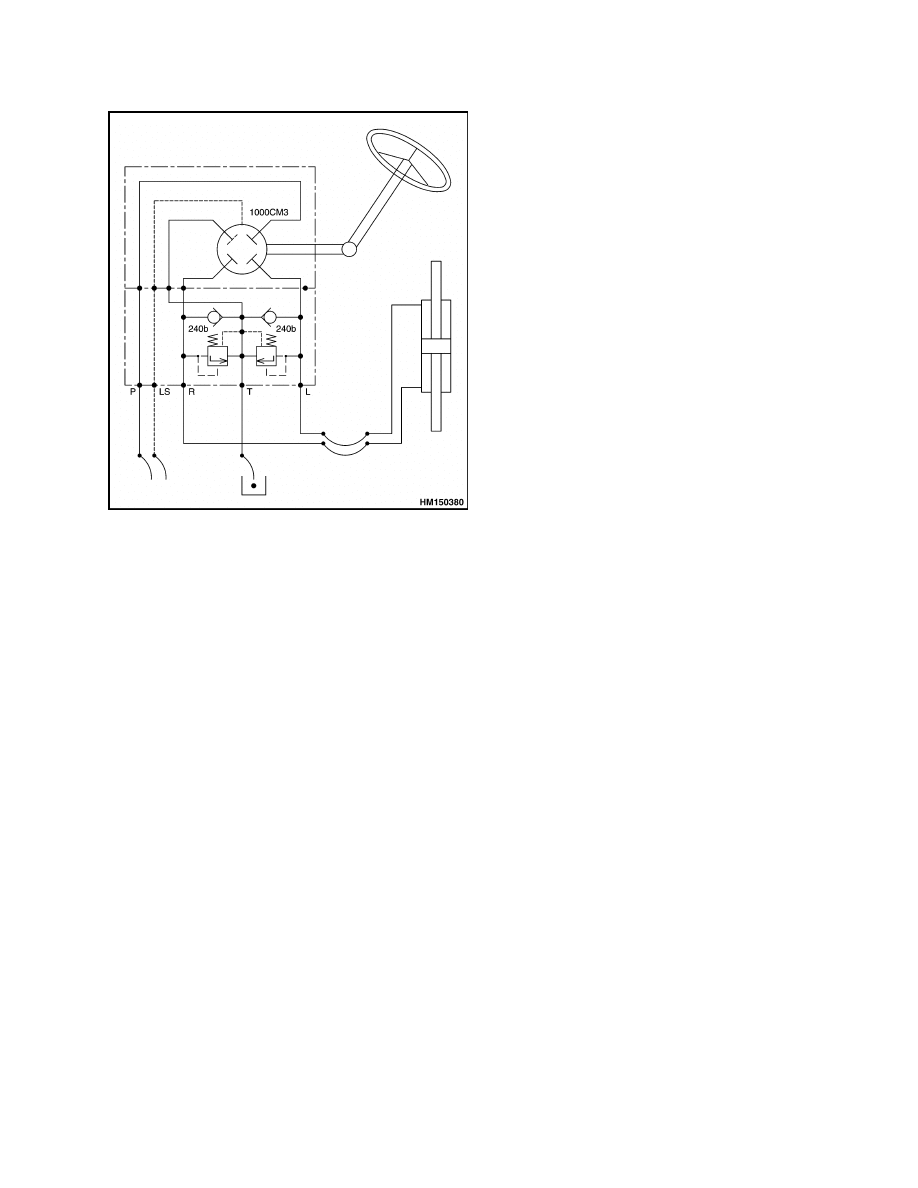
Steering
DESCRIPTION
The supply oil to the steering control unit comes from
port P in the main control valve. Pressure of port P
is controlled by the steering relief valve, which is set
at 220 bar (3191 psi). See Figure 8.
The relief pressure of the steering control unit must
be set a little higher to prevent an almost continuous
flow over the relief. The 20 bar (290 psi) pressure
difference is to absorb shocks caused by objects or
bumps in the road.
Depending on the rotation of the steering wheel, the
steering control unit pressurizes and relieves oil at
the desired side of the steering cylinder.
Flow demand is monitored by the LS (Load Sense)
line.
When the steering wheel is turned, the in-
creased flow demand will drop pressure in the LS
line, which results into an increased supply by the
main pump. A pressure drop in the LS line also ac-
tuates the steering priority valves 1 and 2 at either
side of the main valve, blocking off oil flow to other
functions. See Figure 10.
When the engine is not running, a check valve in the
line between P2 and the steering control unit closes
and permits the steering control unit to operate as
a hydraulic motor. The vehicle is difficult to steer
without sufficient oil supply, but steering is possible.
10
1900 SRM 783
Pilot System
Figure 10. Steering Schematic
ADJUST
NOTE:
Maximum supply pressure is set by the steer-
ing relief valve on the main control valve.
1.
Install a pressure gauge of 600 bar (8702 psi) at
main pressure port M on the main control valve.
2.
With the engine at full throttle and the steering
cylinder at full stroke, adjust the relief valve P2
to obtain 220 bar (3191 psi).
Pilot System
PILOT PUMP
The pilot pump is bolted on the service brake pump
at the front left side of the engine.
The pilot pump provides oil pressure to the following
systems:
• Telescoping retract control valve
• Engine radiator fan motor
• Manipulator pressure valve
• Engine accelerator system
• Joystick
Telescoping Retract Control Valve
Pilot pump oil pressure is directed at the telescoping
retract control valve, which is located on port F of
the steering section of the main control valve. See
Figure 8. When the pressure from joystick port 2
has exceeded 7 bar (102 psi), pilot pump pressure will
be transferred to the holding valve of the telescoping
cylinder, allowing it to be retracted. See Boom 4500
SRM 787.
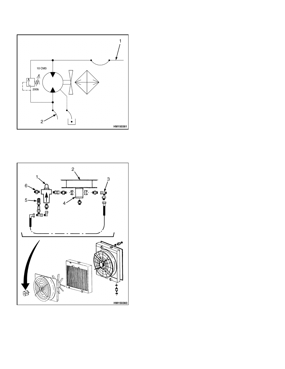
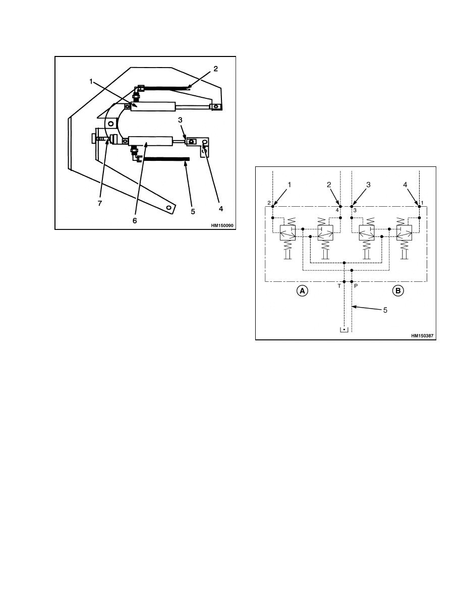
Engine Radiator Fan Motor
Pilot pump pressure drives the hydraulic motor for
the engine radiator fan continuously. Speed of the
fan depends on the oil flow through the manipulator
pressure valve. The manipulator pressure valve is
proportional to engine speed, provided the 200 bar
(2901 psi) relief valve at the hydraulic fan motor is
closed. See Figure 11.
Adjust
To measure pump output pressure install a gauge of
250 bar (3626 psi) at the pressure plug of the relief
valve on the engine radiator fan motor. At idle the
pressure must be around 75 bar (1088 psi). At full
throttle the relief valve must be adjusted to 200 bar
(2901 psi). See Figure 12.
11
Pilot System
1900 SRM 783
1.
TO MANIPULATOR PRESSURE VALVE
2.
FROM PILOT PUMP
Figure 11. Engine Cooling Schematic
Figure 12. Hydraulic Fan Motor
Legend for Figure 12
1.
200 bar (2901 psi) REGULATOR
2.
RADIATOR
3.
TO MANIPULATOR PRESSURE VALVE
4.
FAN MOTOR
5.
PRESSURE PLUG
6.
FROM PILOT PUMP
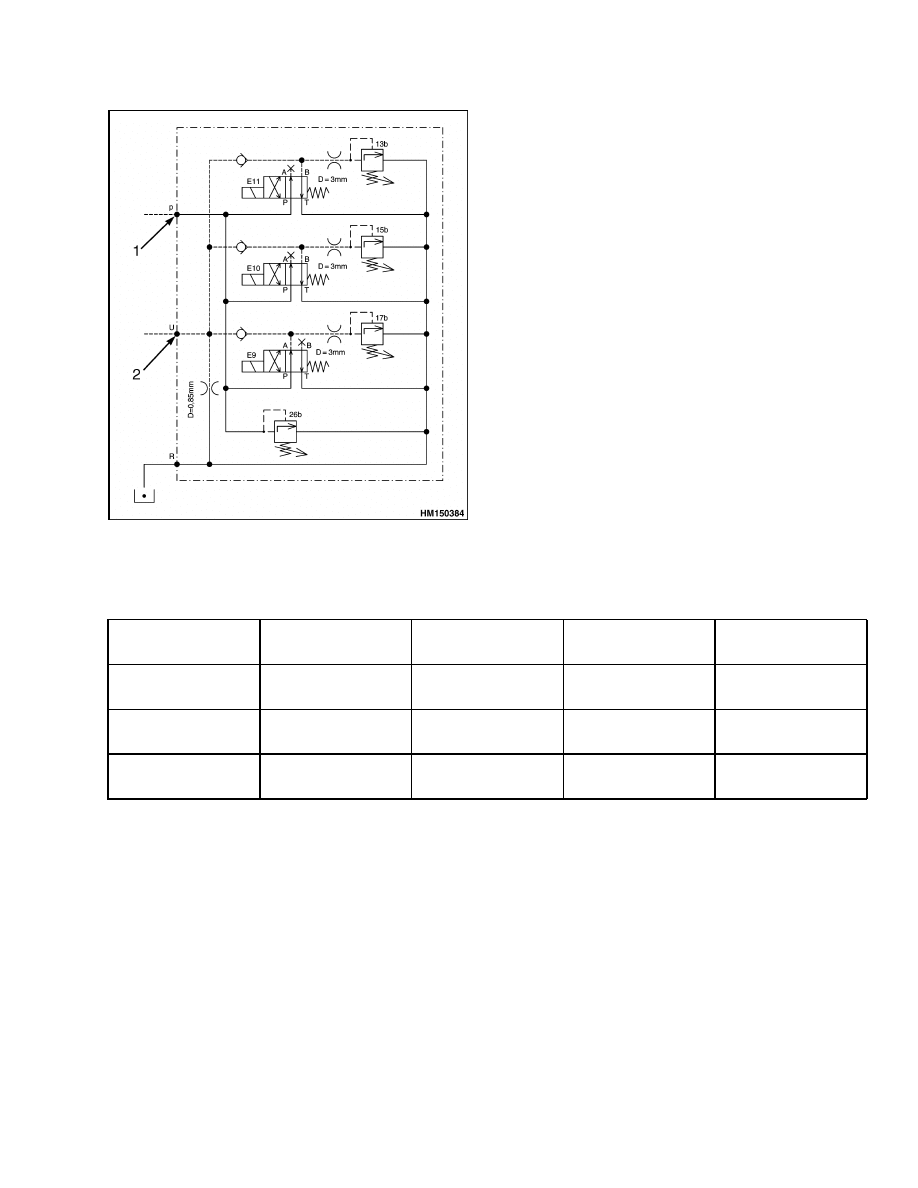
Manipulator Pressure Valve
Description
The manipulator pressure valve reduces pilot pump
pressure to maximum 26 bar (377 psi) and transfers
oil to the joystick and to the throttle pedal.
Depending on the pressure in the LS line, solenoids
E9, E10, and E11 are opened or closed. Each sole-
noid resets to its own set pressure, as long as all pilot
pump supply can escape through the 3 mm (0.12 in.)
restriction behind the relief valve. The lowest pos-
sible relief pressure at lowest pilot pump supply (at
engine idle) is 13 bar (189 psi). At increasing engine
speed, the 3 mm (0.12 in.) restriction will not be able
to relieve all excess oil. Pressure will rise gradually
until the 26 bar (377 psi) relief valve opens.
Pressure at the joystick pressure port is identical to
the output pressure of the manipulator valve. If pres-
sure at the joystick is at a lower level, 13 to 17 bar
(189 to 247 psi), then the proportional control spool in
the main valve can open only partially. The reduced
control spool movement limits oil demand from the
main pump.
Reducing the joystick pressure results in the follow-
ing:
• Preventing engine stalls at low speed and high sys-
tem presssure.
• Smoothing operation of the joystick at high system
pressure.
Operation
The manipulator valve reduces joystick pressure,
depending on the pressure in the load sense line.
Pressure in the LS line is measured by the 170 bar
(2466 psi) and 210 bar (3046 psi) LS pressure
switches.
Depending on the pressures measured,
solenoids E9, E10, and E11 of the manipulator valve
are opened or closed. When E10 and E11 are en-
ergized, the related spools are opened.
When E9
is energized, the related spool blocks oil flow. See
Figure 13 and Table 2.
12
1900 SRM 783
Pilot System
Figure 13. Manipulator Pressure Valve
Schematic
Legend for Figure 13
1.
FROM ENGINE FAN MOTOR
2.
TO JOYSTICK AND ACCELERATOR
Table 2. Pressures in Relation to the Position of Solenoids and Spools
Pressure at LS
Line
E9 Solenoid
Spool
E10 Solenoid
Spool
E11 Solenoid
Spool
Regulated
Control Pressure
Below 170 bar
(2466 psi)
De-energized
Open
De-energized
Blocked
De-energized
Blocked
17 to 26 bar (247
to 377 psi)
170 to 210 bar
(2466 to 3046 psi)
Energized
Blocked
Energized
Open
De-energized
Blocked
15 to 26 bar (218
to 377 psi)
Above 210 bar
(3046 psi)
Energized
Blocked
De-energized
Blocked
Energized
Open
13 to 26 bar (189
to 377 psi)
Adjust
NOTE:
On the hydraulic schematic the pressure plug
is connected with port U.
1.
Attach a gauge of 60 bar (870 psi) at the pressure
plug of the manipulator pressure valve. See Fig-
ure 14.
2.
Adjust the 26 bar (377 psi) relief valve with the
engine at full throttle and without operating the
joystick.
3.
Adjust the 17 bar (247 psi) relief valve at E9 with
the engine at idle and the joystick at full stroke
in the derricking down position.
4.
Adjust the 15 bar (218 psi) relief valve at E10
with the engine at idle, solenoids E9 and E10,
and the joystick at full stroke in the derricking
up position.
5.
Adjust the 13 bar (189 psi) relief valve at E11
with the engine at idle, solenoids E9 and E11 ac-
tivated, and the joystick at full stroke in the der-
ricking up position.
13
Pilot System
1900 SRM 783
1.
SOLENOID (E9)
2.
SOLENOID (E10)
3.
SOLENOID (E11)
4.
RELIEF VALVE 13 bar (189 psi)
5.
RELIEF VALVE 15 bar (218 psi)
6.
RELIEF VALVE 17 bar (247 psi)
7.
RELIEF VALVE 26 bar (377 psi)
8.
3 mm (0.12 in.) RESTRICTION
9.
0.85 mm (0.033 in.) RESTRICTION
10. PRESSURE PLUG
Figure 14. Manipulator Pressure Valve
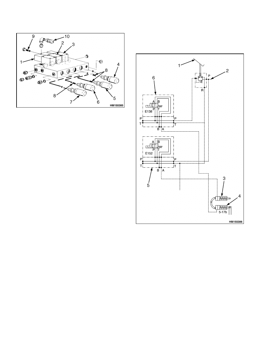
Engine Accelerator System
Oil from the manipulator pressure valve is directed
via the accelerator pedal and the throttle reduction
valve to the accelerator cylinder at the engine. With
increasing pressure, the cylinder moves the lever of
the fuel injection pump towards full throttle. Releas-
ing the accelerator pedal brings engine speed back to
idle. See Figure 15.
Solenoid E138 of the throttle reduction valve is con-
trolled by the transmission control system (APC100).
During transmission speed change, E138 is ener-
gized, which drains the accelerator cylinder at the
engine. When transmission speed change has been
completed, E138 is deactivated again, pressurizing
the accelerator cylinder.
Solenoid E152 of the speed limiter valve is activated
by the APC100 system as soon as a speed of 25 km/h
(16 mph) has been reached. This drains pressure in
the speed limit cylinder, reducing engine speed. See
Figure 16.
1.
ACCELERATOR
2.
FROM MANIPULATOR PRESSURE VALVE
3.
SPEED LIMIT CYLINDER
4.
ACCELERATION CYLINDER
5.
SPEED LIMITING SOLENOID
6.
ACCELERATOR SOLENOID
Figure 15. Engine Accelerator System
Schematic
14
1900 SRM 783
Hydraulic Cooling System
1.
SPEED LIMIT CYLINDER
2.
FROM SPEED LIMITER VALVE
3.
IDLE ADJUSTMENT
4.
INJECTION PUMP LEVER
5.
FROM THROTTLE REDUCTION VALVE
6.
ACCELERATOR CYLINDER
7.
MECHANICAL STOP
Figure 16. Throttle Linkage Arrangement
Adjust
1.
Adjust idle speed to 780 to 800 rpm using the idle
adjustment. See Figure 16.
2.
Adjust the mechanical stop so the maximum en-
gine speed at full throttle is between 2250 to 2350
rpm.
3.
Adjust the speed limit to 25 km/h (16 mph) as
follows:
• Remove the supply hose at the speed limit
cylinder and plug the hose.
• Adjust the mechanical stop to limit engine
speed to 1800 to 1900 rpm.
• Reconnect the supply hose to the speed limit
cylinder.
Joystick
NOTE: The joystick has no serviceable components
and must be exchanged as a unit.
The joystick provides pilot pressure to the control
valves for derricking and telescoping. For descrip-
tion of the derricking and telescoping system, see
Boom 4500 SRM 787 and Figure 17.
A. TELESCOPING
B. DERRICKING
1.
TELESCOPING IN
2.
TELESCOPING OUT
3.
DERRICKING DOWN
4.
DERRICKING UP
5.
FROM MANIPULATOR PRESSURE VALVE
Figure 17. Joystick Schematic
Hydraulic Cooling System
DESCRIPTION
NOTE: There are no adjustments for the hydraulic
cooling system. In case of malfunction, individual
components have to be checked or replaced.
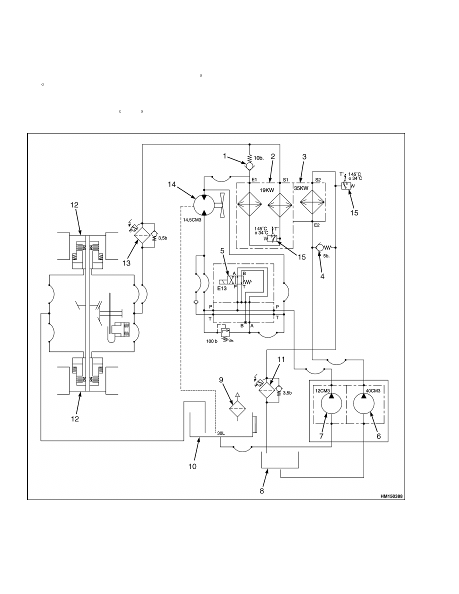
The hydraulic cooling system also serves as the by-
pass filtering system of the main hydraulic system.
The hydraulic oil cooling pump, which is fitted at the
LH front of the engine, provides a continuous oil flow
from the tank, through the radiator and oil filter, and
then back to the tank. See Figure 18.
15
Hydraulic Cooling System
1900 SRM 783
The radiator is protected by a relief valve, which
opens when fluid resistance exceeds 5 bar (73 psi).
When temperature of the radiator has reached 45 C
(113 F), the temperature sensor switches ON sole-
noid E13, causing the oil cooler fan to turn. The
temperature sensor switches OFF when tempera-
ture has come down to 34 C (93 F). Also see Brake
Oil Cooling System.
The oil filter clogging sensor is set slightly lower than
the 3.5 bar (51 psi) of the filter relief pressure. After
it is filtered, oil returns to the main tank.
Figure 18. Brake and Main Hydraulic Oil Cooling System
16
1900 SRM 783
Brake Oil Cooling System
Legend for Figure 18
1.
COLD OIL BYPASS
2.
BRAKE OIL COOLER
3.
HYDRAULIC OIL COOLER
4.
COLD OIL BYPASS
5.
BRAKE COOLING SOLENOID
6.
HYDRAULIC SYSTEM COOLING PUMP
7.
BRAKE SYSTEM COOLING PUMP
8.
MAIN HYDRAULIC TANK
9.
BREATHER
10. BRAKE COOLING OIL TANK
11. HYDRAULIC SYSTEM FILTER
12. SERVICE BRAKE
13. BRAKE SYSTEM OIL FILTER
14. FAN MOTOR
15. TEMPERATURE SENSOR
Brake Oil Cooling System
DESCRIPTION
Cooling system for the brakes is separated from
the rest of the hydraulic system and has a separate
30 liter (8 gal) oil tank at the RH side of the truck.
The brake oil pump provides a continuous oil flow
from the tank, through the radiators and the service
brakes, and then back to the tank.
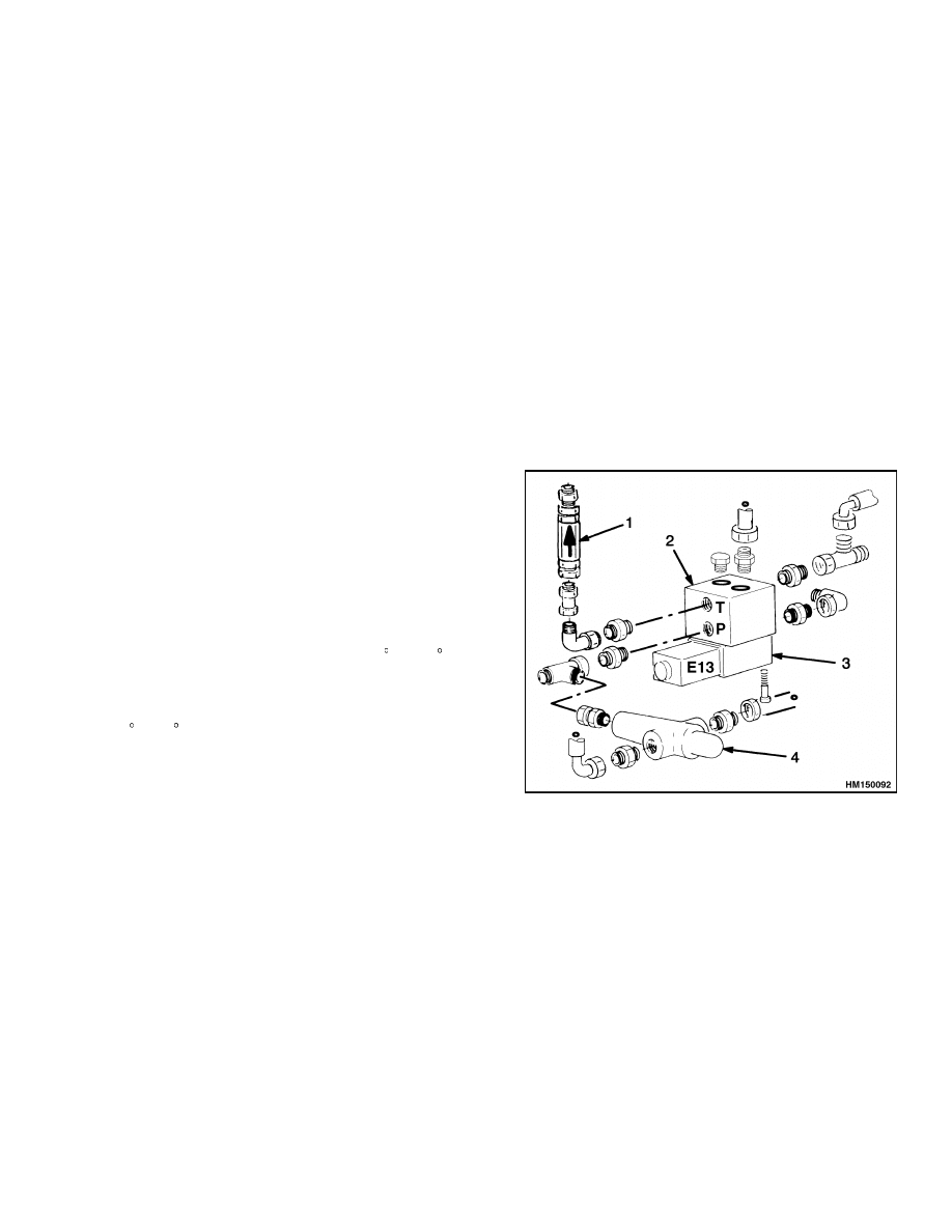
When oil is cold, brake cooling solenoid E13 bypasses
oil flow past the fan motor. As a consequence, the fan
motor will not turn. See Figure 19.
Solenoid E13 is controlled by the temperature sen-
sors in the radiators for the brake system and in the
radiator for the main hydraulic system. When ei-
ther of these sensors has reached 45 C (113 F), so-
lenoid E13 is activated, which forces brake cooling
oil to pass through the fan motor. The temperature
sensors switch OFF when temperature is at or below
34 C (93 F).
When solenoid E13 is activated during higher en-
gine speeds, the inertia of the cooling motor and fan
causes a pressure peak. This pressure peak is cush-
ioned by the 100 bar (1450 psi) relief valve.
The radiators are protected by a relief valve, which
opens when fluid resistance exceeds 10 bar (145 psi).
Before entering the service brakes, oil is filtered. The
filter clogging sensor is set slightly lower than the
3.5 bar (51 psi) of the filter relief pressure.
At each end of the drive axle, three hoses are fitted.
The top hose is for cooling oil supply and the middle
hose is for cooling oil return. The bottom hose con-
nects with the service brake system. After having
cooled the brakes, oil is driven back into the brake
tank.
1.
CHECK VALVE
2.
MANIFOLD
3.
SOLENOID VALVE
4.
RELIEF VALVE
Figure 19. Oil Cooler Solenoid Valve
17
Service Brakes
1900 SRM 783
ADJUST
100 Bar Relief Valve
NOTE:
Maximum pressure will occur directly after
bypassing the temperature switch. Once the fan mo-
tor and fan have reached speed, the pressure mea-
sured will drop. To obtain proper circumstances for
a next measurement, the bypass has to be discon-
nected and the fan has to be stopped. Repeat the
pressure check at least once, after the relief valve has
been set to 100 bar (1450 psi).
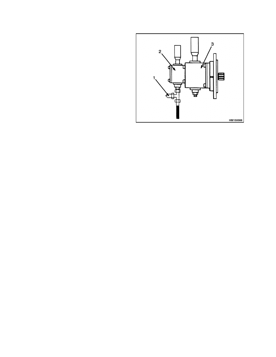
1.
Loosen the relief valve. See Figure 19.
2.
Attach a 250 bar (3626 psi) pressure gauge at the
brake cooling pump. See Figure 20.
3.
Run the engine at full throttle.
4.
Bypass one of the temperature switches at the
radiators to activate solenoid E13.
5.
Adjust the relief valve to 100 bar (1450 psi).
6.
Remove the pressure gauge and bypass.
1.
PRESSURE PLUG
2.
BRAKE COOLING PUMP
3.
HYDRAULIC SYSTEM COOLING PUMP
Figure 20. Oil Cooling Pumps
Service Brakes
DESCRIPTION
NOTE: For further information, see Service Brake
1800 SRM 1038.
The brake oil pump is fitted at the RH side of the en-
gine and provides oil pressure to the brake control
valve. When the brake pedal is applied, the brake
pistons in the drive axle push against the friction
discs for braking action. Releasing the pedal relieves
pressure from the brake pistons. See Figure 21.
The pressure regulator maintains pressure at
160 bar (2321 psi) for the brake pedal valve, park
brake cylinder and accumulator. Excess oil is re-
turned to the tank.
The brake control valve has two pressure switches.
The 105 bar (1523 psi) switch activates the brake
warning light, when regulated brake pressure is be-
low 105 bar (1523 psi). The 5 bar (73 psi) switch acti-
vates the brake lights, when the brakes are applied.
The accumulator has the capability to provide a lim-
ited supply of oil when the brake pump has stopped.
As oil pressure is being used up, the lights for park
brake and low brake pressure will go ON, the APC
100 will switch the transmission into neutral, and
the springs in the park brake caliper will overcome
residual pressure and gradually apply the park
brake.
18
1900 SRM 783
Service Brakes
Figure 21. Service Brake Schematic
19
Parking Brake
1900 SRM 783
Legend for Figure 21
1.
BRAKE PEDAL
2.
ACCUMULATOR
3.
BRAKE CONTROL VALVE
4.
LOW BRAKE PRESSURE SWITCH
5.
PRESSURE REGULATOR
6.
FROM SERVICE BRAKE PUMP
7.
PARKING BRAKE SWITCH
8.
BRAKE COOLING LINE
9.
SERVICE BRAKE
10. BRAKE LIGHT PRESSURE SWITCH
11. PARKING BRAKE SOLENOID
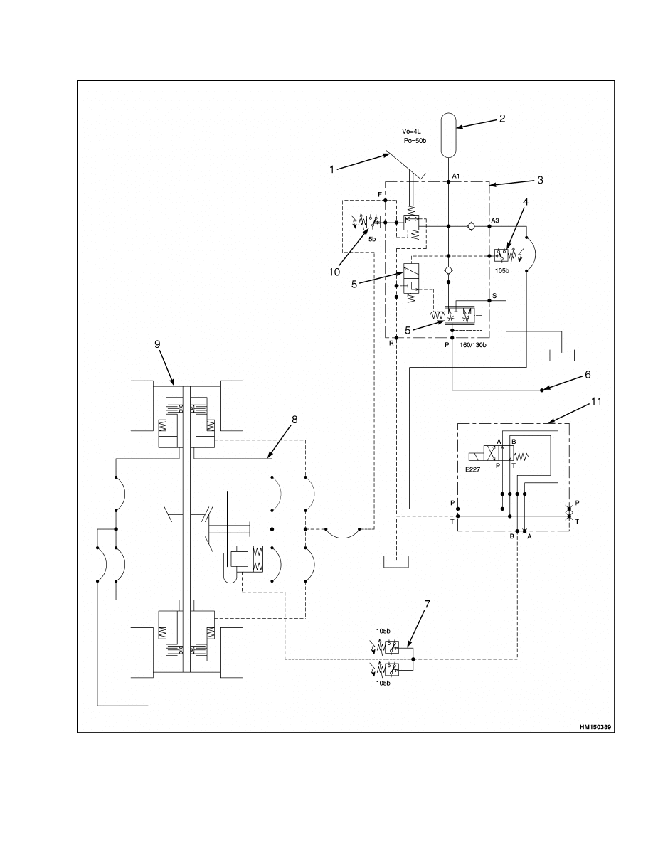
Parking Brake
DESCRIPTION
The parking brake system uses a disc brake that is
installed at the rear of the differential. Spring force
applies the disc brake. When applying oil pressure
to the piston, spring pressure is overcome, which re-
leases the parking brake.
Oil pressure from the brake control valve is admit-
ted to the disk brake by energizing parking brake
solenoid E227. When pressure has reached 105 bar
(1523 psi), the two pressure switches will open. One
is for the Park Brake Warning Light to go OFF and
the second switch is for the APC 100 system to allow
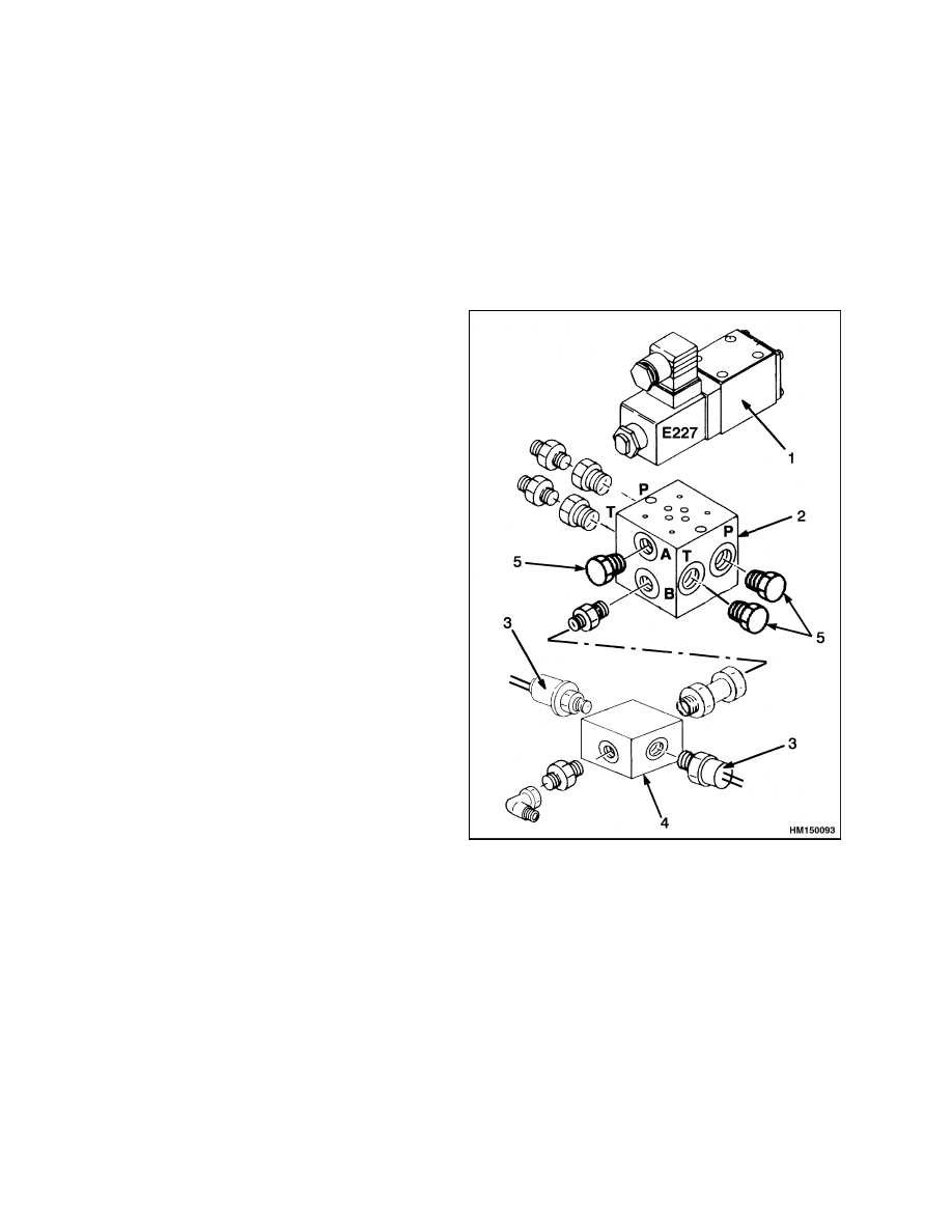
a gear to be selected. See Figure 22.
1.
SOLENOID VALVE
2.
MANIFOLD
3.
PRESSURE SWITCH
4.
PARKING BRAKE SWITCH
5.
PLUG
Figure 22. Parking Brake Solenoid Valve
20


TECHNICAL PUBLICATIONS
1900 SRM 783
1/04 (11/03)(6/03)(10/00)(1/00) Printed in United Kingdom
Document Outline
- toc
- tables
Wyszukiwarka
Podobne podstrony:
1564283 1900SRM1107 (01 2004) UK EN
1564283 1900SRM1107 (01 2004) UK EN
897495 2200SRM0514 (01 2004) UK EN
1564268 2200SRM1106 (01 2004) UK EN
897494 1900SRM0513 (06 2004) UK EN
1554630 1900SRM1077 (06 2004) UK EN
1556871 2200SRM1105 (01 2004) UK EN
1554631 2000SRM1085 (03 2004) UK EN
1554635 8000SRM1079 (06 2004) UK EN
897506 4000SRM0521 (05 2004) UK EN
897480 1400SRM0499 (10 2004) UK EN
910091 1900SRM0097 (08 2005) UK EN
więcej podobnych podstron