BRAKE SYSTEM
J2.00-3.20XM (J40-60XM, J40-60XM
2
) [A216];
J2.00-3.20XM (J40-65Z) [A416]
PART NO. 897653
1800 SRM 566

SAFETY PRECAUTIONS
MAINTENANCE AND REPAIR
• When lifting parts or assemblies, make sure all slings, chains, or cables are correctly
fastened, and that the load being lifted is balanced. Make sure the crane, cables, and
chains have the capacity to support the weight of the load.
• Do not lift heavy parts by hand, use a lifting mechanism.
• Wear safety glasses.
• DISCONNECT THE BATTERY CONNECTOR before doing any maintenance or repair
on electric lift trucks. Disconnect the battery ground cable on internal combustion lift
trucks.
• Always use correct blocks to prevent the unit from rolling or falling. See HOW TO PUT
THE LIFT TRUCK ON BLOCKS in the Operating Manual or the Periodic Mainte-
nance section.
• Keep the unit clean and the working area clean and orderly.
• Use the correct tools for the job.
• Keep the tools clean and in good condition.
• Always use HYSTER APPROVED parts when making repairs. Replacement parts
must meet or exceed the specifications of the original equipment manufacturer.
• Make sure all nuts, bolts, snap rings, and other fastening devices are removed before
using force to remove parts.
• Always fasten a DO NOT OPERATE tag to the controls of the unit when making repairs,
or if the unit needs repairs.
• Be sure to follow the WARNING and CAUTION notes in the instructions.
• Gasoline, Liquid Petroleum Gas (LPG), Compressed Natural Gas (CNG), and Diesel fuel
are flammable. Be sure to follow the necessary safety precautions when handling these
fuels and when working on these fuel systems.
• Batteries generate flammable gas when they are being charged. Keep fire and sparks
away from the area. Make sure the area is well ventilated.
NOTE: The following symbols and words indicate safety information in this
manual:
WARNING
Indicates a condition that can cause immediate death or injury!
CAUTION
Indicates a condition that can cause property damage!

Brake System
Table of Contents
TABLE OF CONTENTS
General ...............................................................................................................................................................
Description and Operation ................................................................................................................................
Service Brakes ...............................................................................................................................................
Master Cylinder .............................................................................................................................................
Parking Brake................................................................................................................................................
Service Brake Repairs .......................................................................................................................................
Remove and Disassemble ..............................................................................................................................
Clean ..............................................................................................................................................................
Inspect ............................................................................................................................................................
Assemble and Install .....................................................................................................................................
Adjust .............................................................................................................................................................
Parking Brake Repair........................................................................................................................................
Remove and Disassemble ..............................................................................................................................
Assemble and Install .....................................................................................................................................
Adjust .............................................................................................................................................................
Master Cylinder Repair .....................................................................................................................................
Remove ...........................................................................................................................................................
Clean and Inspect ..........................................................................................................................................
Repair .............................................................................................................................................................
Install .............................................................................................................................................................
Service Brakes Adjustment ...............................................................................................................................
Brake Pedal Adjustment ...................................................................................................................................
Master Cylinder Adjustment.............................................................................................................................
Brake System Air Removal ...............................................................................................................................
Parking Brake Not Applied Switch Test...........................................................................................................
Torque Specifications .........................................................................................................................................
Troubleshooting..................................................................................................................................................
This section is for the following models:
J2.00-3.20XM (J40-60XM, J40-60XM
2
) [A216];
J2.00-3.20XM (J40-65Z) [A416]
©2005 HYSTER COMPANY
i

"THE
QUALITY
KEEPERS"
HYSTER
APPROVED
PARTS

1800 SRM 566
Description and Operation
General
This section has a description and the service procedures for the parts of the brake system. The brake system
includes the following parts: master cylinder, brake shoes, wheel cylinders, and parking brake system. A trou-
bleshooting section is included at the end of this section.
Description and Operation
SERVICE BRAKES
A service brake assembly is installed on the mounts
at each end of the drive axle. The parts of the service
brake assembly are shown in Figure 3 and Figure 4.
When the brake pedal is pushed, fluid pressure from
the master cylinder causes the pistons in the wheel
cylinders to extend. The pistons expand the brake
shoes against the drums. See Figure 9.
The clearance between the brake shoes and the brake
drum is adjusted automatically. An adjuster link-
age turns the adjuster wheel to adjust the clearance.
When the lift truck moves in the REVERSE direction
and the brakes are applied, the rear brake shoe and
the adjuster links move with the drum. This linkage
moves the adjuster lever to rotate the adjuster wheel.
The adjuster wheel can turn only when there is clear-
ance between the lining of the brake shoe and the
brake drum. The adjuster wheel can also be turned
with a tool. A hole in the brake drum gives access to
the adjuster wheel.
MASTER CYLINDER
The master cylinder is designed for a dual circuit sys-
tem. The master cylinder has two separate pistons
that operate in the single bore of the master cylin-
der. The reservoir for the fluid is pressed into the
two ports on top of the master cylinder and held in
position by seals. When the brake pedal is pushed,
the push rod moves the piston assemblies. The oper-
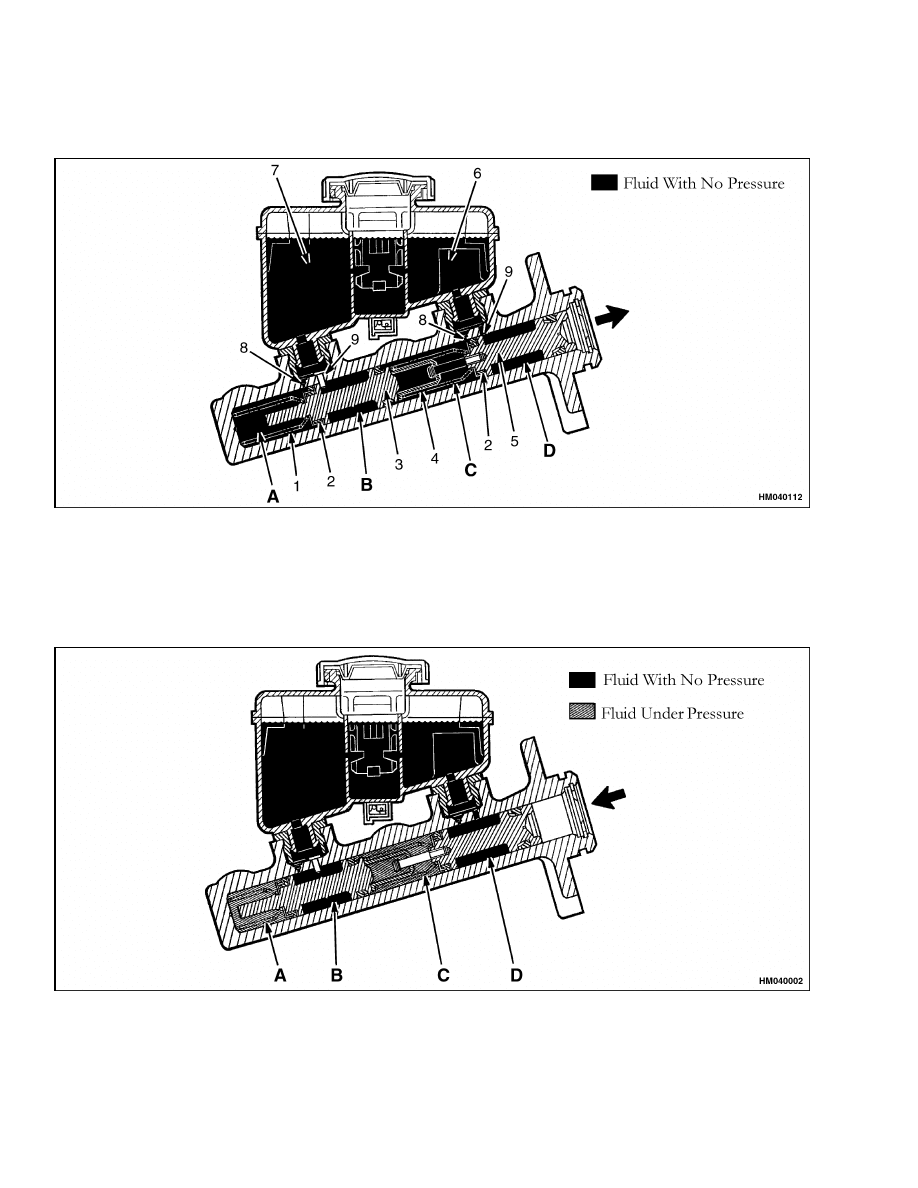
ation of the master cylinder is as follows:
When the brakes are OFF, the hydraulic fluid can
move freely between the dual circuit system and the
separate chambers of the fluid reservoir. See Fig-
ure 1.
When the brake pedal is released, the return springs
cause the pistons to retract faster than the fluid. This
action causes a vacuum between the fluid in cham-
bers A and C. The vacuum causes the seals to change
shape. When the seals change shape, they permit
the fluid in chambers B and D to flow through the
holes in the pistons and past the seals into chambers
A and C. The supply holes in the cylinder body sup-
plies fluid as the flow moves from the one chamber to
the other chamber. The fluid returns to the reservoir
through the bypass holes when the pistons are fully
retracted.
When the brake pedal is pressed, the primary pis-
ton moves in the cylinder bore. This movement cre-
ates hydraulic pressure that combines with the force
of the primary spring. These combined forces over-
come the secondary spring force and move the sec-
ondary piston in the bore with the primary piston.
The first movement of both pistons pushes the seals
past the bypass holes in the chambers A and C. This
action applies pressure to the fluid in those cham-
bers and causes fluid to flow to the chambers of the
two separate systems. The fluid in chambers B and
D is not affected by movement of the pistons. This
fluid can move freely between the piston chambers
and the chambers of the fluid reservoir, before and
during brake application. See Figure 2.
If a failure occurs in one of the dual circuits, the other
circuit will apply one of the service brakes. This fail-
ure will cause the brake pedal to travel farther when
the brakes are applied, but the service brakes on one
drive wheel will operate. This failure of one of the
brake circuits can cause the lift truck to turn toward
the drive wheel with the good brake when the brakes
are applied. The operator must control the direction
of the lift truck with the steering when the brakes
are applied during this condition.
The reservoir is equipped with an indicator for low
fluid level. A float in the reservoir moves up and
down with the fluid level. When the fluid level is low,
a magnet on the float activates a switch in the bot-
tom of the reservoir. This switch energizes a warning
light on the instrument cluster.
PARKING BRAKE
The parking brake system uses the service brake
shoes.
Additional linkage activates the parking
brake system. When the pedal is moved to apply
the parking brake, the cables and linkage expand
1
Description and Operation
1800 SRM 566
the brake shoes against the drums. The design of
the parking brake linkage adjusts each cable so that
the tension is the same when the pedal is moved to
apply parking brake. See Figure 10.
1.
SECONDARY SPRING
2.
SEAL
3.
SECONDARY PISTON
4.
PRIMARY SPRING
5.
PRIMARY PISTON
6.
PRIMARY FLUID CHAMBER
7.
SECONDARY FLUID CHAMBER
8.
BYPASS HOLES
9.
SUPPLY HOLES
Figure 1. Master Cylinder Brake OFF and Brake RELEASED
Figure 2. Master Cylinder Brake APPLIED
2

1800 SRM 566
Service Brake Repairs
Service Brake Repairs
REMOVE AND DISASSEMBLE
WARNING
Brake linings can contain dangerous fibers.
Breathing the dust from these brake linings
is a cancer or lung disease hazard.
Do not
create dust!
Do not clean brake parts with
compressed air or by brushing. Use vacuum
equipment approved for brake dust or follow
the Clean procedure in this section. When the
brake drums are removed, do not create dust.
Do not sand, grind, chisel, hammer, or change
linings in any way that will create dust. Any
changes to brake linings must be done in a re-
stricted area with special ventilation. Protec-
tive clothing and a respirator must be used.
1.
See the procedure How To Put a Lift Truck on
Blocks in the Periodic Maintenance section
of the service manual or the Operating Man-
ual. Tilt mast fully backward. Put blocks under
mast. Tilt mast forward until wheels just touch
the floor. Stop motor. Put blocks under frame of
lift truck.
2.
If tilt does not function, use a hydraulic jack,
crane, or another lift truck to lift drive wheels
until they just touch the floor. Put blocks under
frame of lift truck.
3.
Remove capscrews that hold axle shaft to hub.
Remove axle shaft.
4.
Release parking brake.
Bend lock plate and
remove nut that holds axle bearing.
Remove
washer and bearing cone.
5.
Put grease on floor so wheel assembly will slide
easily from axle tube.
Pull wheel assembly
from lift truck.
If wheel assembly cannot be
removed easily, remove wheel and use a small
screwdriver to push adjuster actuator away from
adjuster wheel. Use a brake adjustment tool or
a screwdriver to turn adjuster wheel to loosen
brake shoes. Install wheel and then remove hub
and drum assembly. Do not damage grease seal
when removing hub.
WARNING
When the brake shoes are removed, do not cre-
ate dust in the air. See the Clean procedure in
this section.
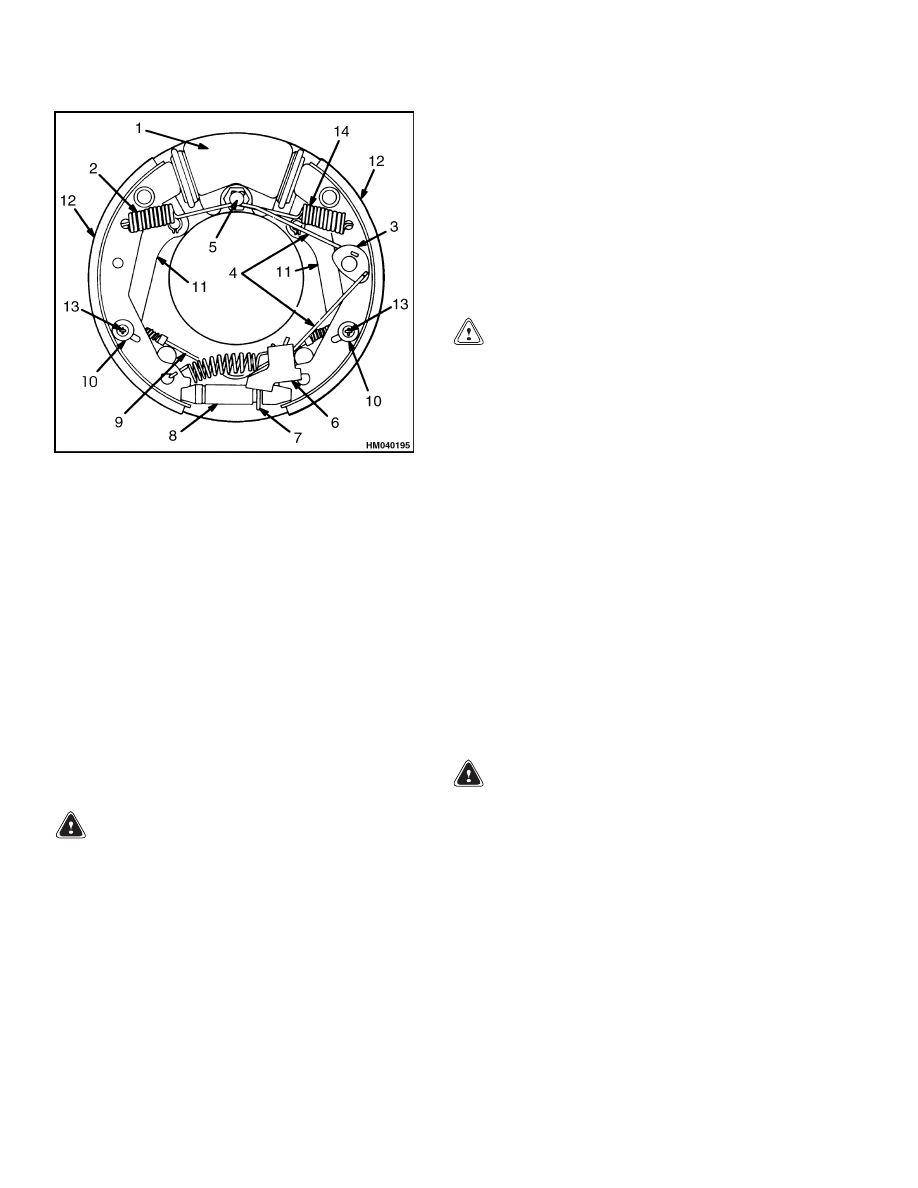
6.
Remove return springs with spring pliers. See
Figure 3.
NOTE: The return springs are not the same part
number. Make sure springs are installed in same
positions from which they were removed.
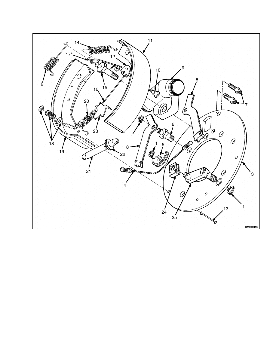
7.
Remove retainers, springs, and retainer pins
that hold brake shoes to back plate. See Figure 4.
Remove brake shoes and adjuster assembly.
NOTE: The adjuster wheel for the left brake is not
the same as the adjuster wheel for the right brake.
The adjuster wheel for the right brake has left-hand
threads.
8.
Remove brake line from wheel cylinder. Remove
wheel cylinder.
9.
Remove dust covers, pistons, cups, and springs
from wheel cylinder. See Figure 5.
NOTE: The back plate is not normally removed from
the axle housing for brake repairs. Six special cap-
screws are used to fasten the back plate to the axle
mount and the locking function of the capscrews is re-
duced if they are removed. The five capscrews with
5/8 inch thread are tightened to 245 N•m (181 lbf ft).
The capscrew with 1/2 inch thread is tightened to
125 N•m (92 lbf ft).
10. Remove snap rings from parking brake levers.
Remove parking brake levers from back plate.
3
Service Brake Repairs
1800 SRM 566
NOTE: LEFT SIDE SHOWN.
1.
WHEEL CYLINDER
2.
MAROON RETURN SPRING
3.
PIVOT PLATE
4.
LINK
5.
ANCHOR
6.
ADJUSTER WHEEL ACTUATOR
7.
ADJUSTER WHEEL
8.
ADJUSTER NUT
9.
PARKING BRAKE CABLE
10. RETAINER
11. PARKING BRAKE LEVER
12. BRAKE SHOE
13. HOLD DOWN PIN
14. GREY RETURN SPRING
Figure 3. Brake Assembly (Left Brake Assembly
Shown)
CLEAN
WARNING
Do not use an oil solvent to clean the master
cylinder, wheel cylinder, or the brake linings.
Use a solvent approved for cleaning of brake
parts. Do not permit oil or grease in the brake
fluid or on the brake linings. Oil and grease
will cause damage and leaks in the seals of
a brake system. The brakes will not operate
correctly if oil, grease, or brake fluid is on the
brake linings.
Cleaning solvents can be flammable and toxic
and can cause skin irritation.
When using
cleaning solvents, always follow the safety
instructions of the solvent manufacturer.
1.
Do not release brake lining dust from brake lin-
ings into air when brake drum is removed.
2.
Use a solvent approved for cleaning of brake
parts to wet brake lining dust. Follow instruc-
tions and cautions of manufacturer for use of
solvent. If a solvent spray is used, do not create
brake lining dust with spray.
CAUTION
Do not permit oil or grease on the brake linings.
Use a brake cleaning fluid as necessary to clean
linings that will not be replaced.
3.
When the brake lining dust is wet, clean parts.
Put any cloth or towels in a plastic bag or an
airtight container while they are still wet. Put
a DANGEROUS FIBERS warning label on the
plastic bag or airtight container.
4.
Any cleaning cloths that will be washed must be
cleaned so fibers are not released into the air.
INSPECT
1.
Inspect bore of wheel cylinder for holes or
scratches. Replace wheel cylinder assembly if
there is any damage.
2.
Inspect return springs for wear or damage. In-
spect back plate for wear where brake shoes
touch back plate. Remove any grooves or replace
a worn or damaged back plate.
WARNING
The brake shoes on both wheels must be re-
placed if any shoe is damaged. The brake per-
formance on both ends of an axle must be equal
or the lift truck can be difficult to steer when
the brakes are applied.
3.
Inspect brake shoes for cracks or damage.
If
linings or shoes are worn or damaged, replace
brake shoes. Maximum wear is to within 1 mm
(0.04 in.) of contact with rivets or metal shoe on
bonded linings. Brake shoes must be replaced in
complete sets. Inspect brake drums for cracks or
damage. Replace any damaged parts.
4
1800 SRM 566
Service Brake Repairs
NOTE: LEFT SIDE SHOWN.
1.
SNAP RING
2.
MAROON RETURN SPRING
3.
BACK PLATE
4.
CABLE
5.
CABLE GUIDE
6.
SPECIAL CAPSCREW
7.
CAPSCREWS
8.
PARKING BRAKE LEVER
9.
WHEEL CYLINDER
10. PIVOT PIN
11. REAR BRAKE SHOE
12. PIVOT PLATE
13. HOLD DOWN PIN (2)
14. GREY RETURN SPRING
15. SPECIAL CAPSCREW
16. ADJUSTER LINK
17. ADJUSTER LINK*
18. RETAINER SPRING
ASSEMBLY
19. FRONT BRAKE SHOE
20. SPRING
21. ADJUSTER NUT
22. ADJUSTER WHEEL
23. ADJUSTER WHEEL
ACTUATOR
24. CABLE RETAINER
25. CRANK
*DO NOT BEND OR PUT STRESS ON THE UPPER LINK BY FORCING THE HOOK END ON OR AROUND THE
POST ON THE SPECIAL CAPSCREW.
Figure 4. Service Brake Parts
5
Service Brake Repairs
1800 SRM 566
NOTE: If grooves must be removed from the brake
drums, do not grind more than 1.5 mm (0.060 in.)
from the internal diameter of the brake drum. The
maximum limit of the internal diameter of the brake
drum is 262 mm (10.32 in.). If the internal diameter
is larger than the limit, replace brake drum.
4.
Inspect brake drum for deep grooves or other
damage.
5.
The teeth of the adjuster wheel must not be worn.
The adjuster wheel must turn freely. Check ad-
juster links for damage.
6.
Make sure parking brake cables are in good con-
dition.
7.
Check grease seals and surfaces of seals for wear
or damage.
ASSEMBLE AND INSTALL
1.
Assemble wheel cylinder. See Figure 5. Use only
HYSTER APPROVED parts.
2.
Install wheel cylinder on back plate. Make sure
special fitting for removing air is in top hole. Put
Loctite
®
271 on threads of capscrews. Tighten
two capscrews with 7/16 inch thread to 78 to
91 N•m (58 to 67 lbf ft). Tighten two capscrews
with 1/2 inch thread to 91 to 102 N•m (67 to
75 lbf ft).
3.
Put retainer pins that hold brake shoes through
back plate. Install back plate on axle housing.
4.
Tighten two special capscrews for parking brake
levers to 245 N•m (181 lbf ft). See Figure 4.
Tighten capscrews that hold back plate to axle
housing to 245 N•m (181 lbf ft). Install washer
and special capscrew that is the anchor for the
return springs. This capscrew must be tightened
to 125 N•m (92 lbf ft). Make sure washer is in-
stalled so capscrew does not loosen during oper-
ation.
5.
Install parking brake levers and cable. Install
snap rings. Install cable guide and snap ring on
crank for parking brake.
1.
PORT FOR SPECIAL FITTING
2.
INLET PORT
3.
BRAKE SHOE
4.
DUST COVER
5.
WHEEL CYLINDER
6.
SPRING
7.
CUP
8.
PISTON ASSEMBLY
Figure 5. Wheel Cylinder
6

1800 SRM 566
Service Brake Repairs
6.
Install pivot pin through brake shoe that is to-
ward rear of lift truck. Install links in pivot plate.
Install pivot plate, links, and cotter pin.
NOTE: The upper link for the left brake assembly is
not the same as the upper link for the right brake
assembly. Install pivot plate so the letter L is seen on
the left brake assembly. Install pivot plate on right
brake assembly so the letter R is seen.
7.
Lubricate back plate with a small amount of
grease where the shoes touch.
Install brake
shoes. Install retainer spring assembly. Put a
spring seat, spring, and retainer on pin. Push
retainer onto pin and rotate retainer 90 degrees
to lock pin into retainer.
Install other spring
assembly.
WARNING
The threads of the adjuster wheel are not the
same for each brake assembly. If the adjuster
wheel assemblies are installed on the wrong
brake, the brake shoe clearance will increase
each time the brakes are applied. The adjuster
wheel for the right brake has left-hand threads.
The adjuster wheel for the left brake has right-
hand threads.
8.
Put an antiseize compound on threads of adjuster
wheel. Install adjuster wheel assembly between
two brake shoes. Make sure adjuster wheel is
toward rear of lift truck.
Turn adjuster wheel into adjuster nut so adjuster
assembly is in its shortest position. This action
permits brake drum to be easily installed over
brake shoes.
9.
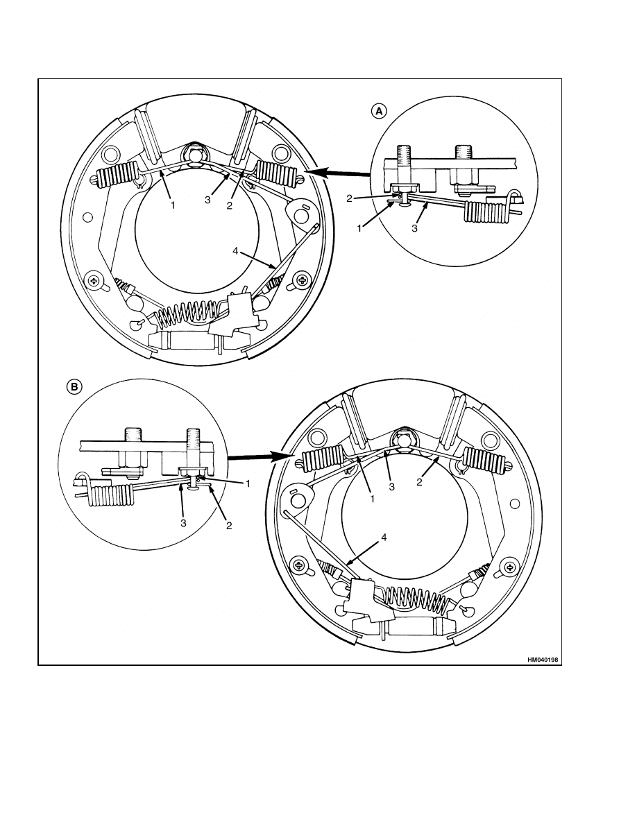
Install link in adjuster wheel actuator.
Put
adjuster wheel actuator in the hole in brake
shoe. Fasten spring to adjuster wheel actuator
and brake shoe. The spring must be installed
in the position shown in Figure 6. Install re-
turn springs for brake shoes. Make sure return
springs are installed in correct positions. See
Figure 6. A gray spring is always installed on
right brake shoe.
10. Make sure bottom edge of adjuster wheel actua-
tor is just above center of teeth of adjuster wheel.
Bend lower link to align adjuster wheel actuator.
NOTE: To prevent damage to the inner oil seal when
installing the hub, the hub and drum assembly can
be temporarily fastened to the wheel.
Align the
height of the axle housing with hub bearings. Put
grease under wheel and slide wheel toward axle
housing.
Install outer bearing and nut.
Remove
wheel from hub so the clearance of the brake shoes
can be adjusted.
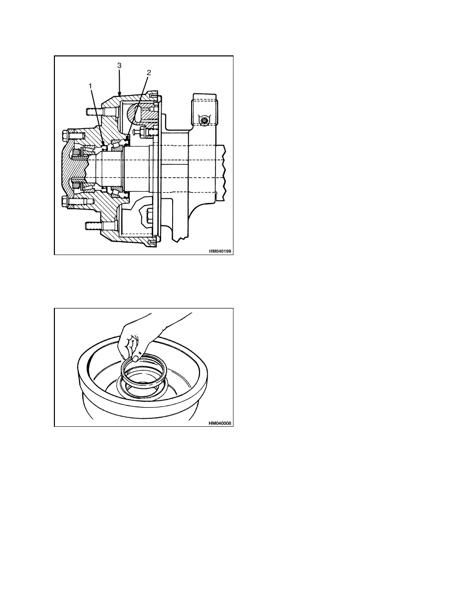
11. Clean hub bearings and lubricate them with
wheel bearing grease. Install hub bearings and
seals in hub. Install brake drum and hub on axle
housing. See Figure 7 and Figure 8.
12. Adjust hub bearings by tightening nut to
205 N•m (151 lbf ft) while rotating hub. Loosen
nut until hub turns freely.
The torque must
be less than 27 N•m (20 lbf ft).
Tighten nut
to 34 N•m (25 lbf ft) or until first alignment
position after 34 N•m (25 lbf ft). Bend lock plate
over nut.
CAUTION
If there is too much clearance, the automatic
adjusters will not operate. If the clearance is
too small, the automatic adjuster cannot turn
the adjuster wheel to increase the clearance
and the adjuster wheel will not turn until
the brake shoes wear.
If the adjuster wheel
does not move for a long operating period, the
adjuster link can wear a spot on the adjuster
wheel so that it will not turn correctly.
NOTE: If the brake shoes were not replaced, loosen
adjuster wheel approximately 25 teeth.
13. Adjust the clearance of the brake shoes. Put a
brake adjustment tool or a screwdriver through
hole in drum. Turn adjuster wheel so teeth of
adjuster wheel nearest back plate move upward.
Turn adjuster wheel until hub will not turn. Pull
actuator away from adjuster wheel and turn ad-
juster wheel approximately 15 teeth in opposite
direction. The brakes will adjust to correct clear-
ance when they are applied while lift truck is
traveling in REVERSE direction.
14. Put sealant on flange of axle shaft.
Install
axle shaft and capscrews. Tighten capscrews to
98 N•m (72 lbf ft).
7
Service Brake Repairs
1800 SRM 566
A. LEFT SIDE
B. RIGHT SIDE
1.
SPRING FOR (LEFT) SHOE (MAROON)
2.
SPRING FOR (RIGHT) SHOE (GRAY)
3.
UPPER ADJUSTER LINK
4.
LOWER ADJUSTER LINK
Figure 6. Springs Installation
8
1800 SRM 566
Service Brake Repairs
1.
OUTER SEAL
2.
INNER SEAL
3.
BRAKE DRUM
Figure 7. Grease Seals Location
Figure 8. Inner Grease Seal Installation
ADJUST
1.
Remove air from brake hydraulic system. See the
procedure Brake System Air Removal.
2.
Install wheel on hub.
Tighten nuts to 237 to
305 N•m (175 to 225 lbf ft).
3.
Tilt mast backward or lift the truck to remove
blocks. Push on brake pedal. The pedal must not
touch floor plate. Move lift truck in REVERSE
and push on brake pedal to permit adjusting
mechanism to operate.
Repeat this operation
several times.
4.
The service brakes must be adjusted before the
parking brake can be adjusted. See Figure 9 and
Figure 10 and the following paragraphs in this
section for the correct adjustment of the parking
brake.
9
Service Brake Repairs
1800 SRM 566
1.
CAPSCREW
2.
BRAKE PEDAL
3.
FLOOR PLATE
4.
LOCK NUT
5.
PUSH ROD
6.
LOCK NUT
7.
MASTER CYLINDER
8.
BRAKE ASSEMBLY
9.
BRAKE LINES
Figure 9. Service Brake
10

1800 SRM 566
Parking Brake Repair
Parking Brake Repair
REMOVE AND DISASSEMBLE
If the lever assembly for the parking brake must be
removed from the frame, use the following procedure
(see Figure 10):
1.
Use blocks next to the wheels to make sure the
lift truck cannot move.
Release the parking
brake.
2.
Turn the adjustment knob so that the link is at
the bottom of the adjustment slot.
3.
Remove the cotter pin and pin to disconnect the
parking brake cable from the brake assembly.
4.
Remove the cotter pin and anchor pin that con-
nect the link to the parking brake assembly.
5.
Remove the nuts and washers that hold the park-
ing brake assembly to the bracket. Remove the
capscrews and spacers.
6.
Remove the cotter pin, washer, and anchor pin
from the link.
ASSEMBLE AND INSTALL
If the lever assembly for the parking brake was re-
moved from the frame, use the following procedure
for installation:
1.
Make sure the parking brake lever is in the re-
leased position. Turn the adjustment knob until
the link is adjusted to the bottom of the adjust-
ment slot.
2.
Install the ends of the cables into the compen-
sator. Install the anchor pin, washer, and cotter
pin into the parking brake assembly. Make sure
the anchor pin is through the link and compen-
sator.
3.
Install the mounting bolts through the cable
clamps and spacers. Mount the assembly to the
bracket.
4.
Before tightening the mounting capscrews, push
down the parking brake assembly to make sure
it is in contact with the frame bracket.
5.
The following procedure must be used to connect
the link to the parking brake assembly and the
brake pedal assembly: put the parking brake
lever in the applied position. Install the anchor
pin in the hole in the link that will adjust the
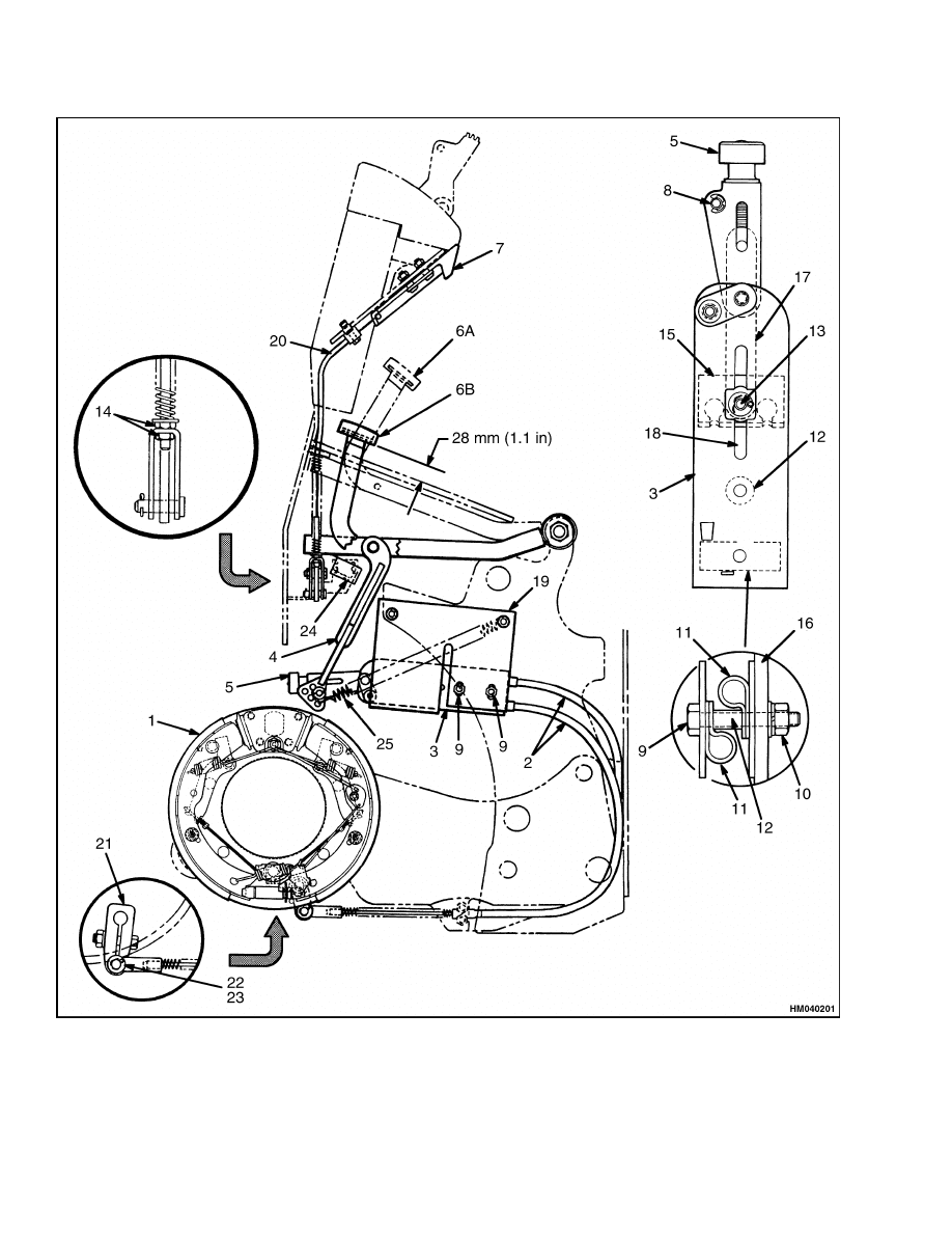
bottom side of the parking brake pedal to 28 mm
(1.1 in.) above the frame. See Figure 10. Install
the cotter pins. Install the return spring in an
empty hole in the link.
6.
With the brake in the applied position, adjust
and tighten the nuts on the end of the cable to
remove all the free play from the release handle.
7.
With the parking brake applied, adjust the
switch so that the lever on the switch moves 1
to 3 mm (0.04 to 0.12 in.) beyond the operating
point.
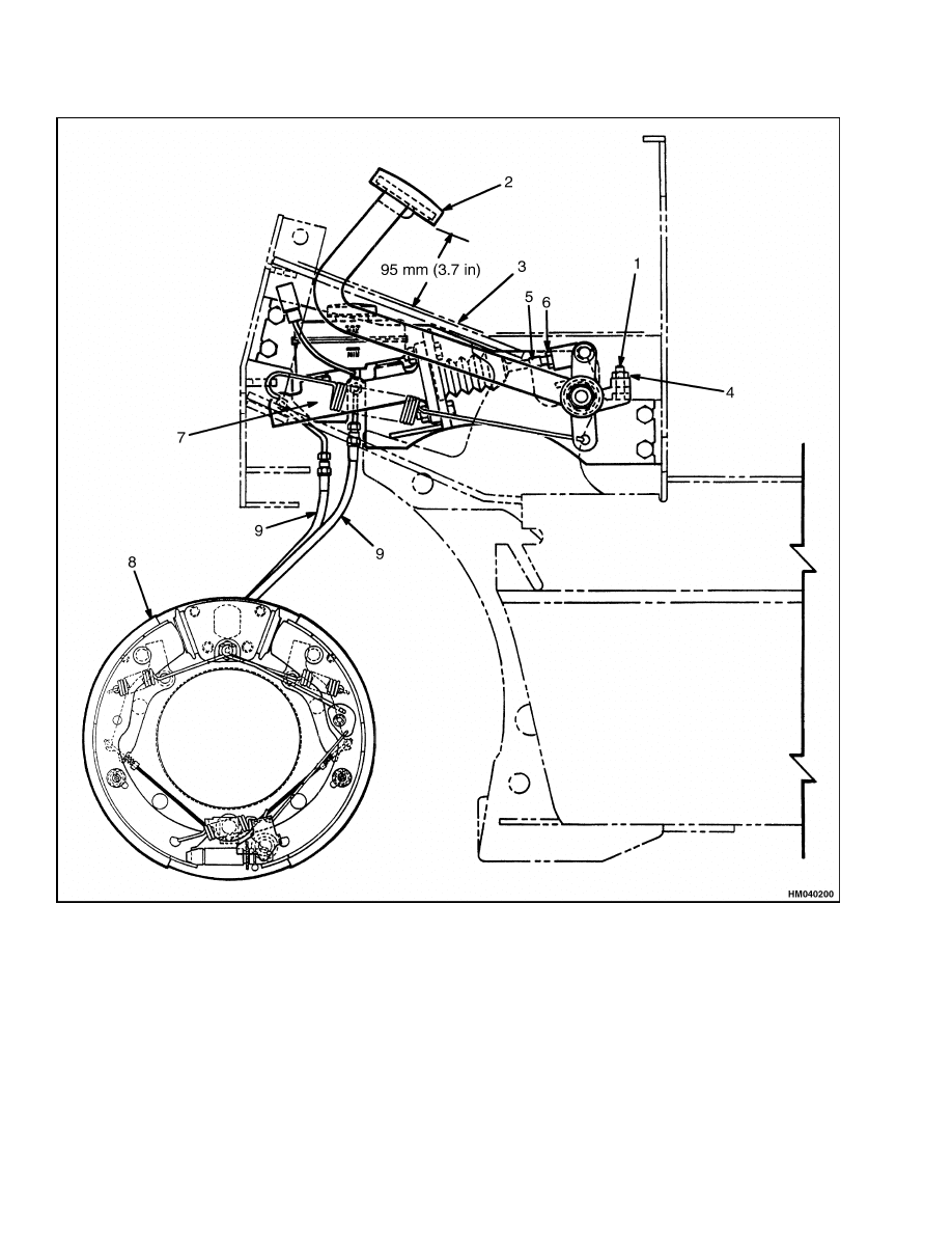
ADJUST
Make sure that the service brakes are adjusted and
the operation of the automatic adjuster mechanism
is correct before the parking brake is adjusted. See
Figure 10.
1.
Turn the adjustment knob to raise the link and
tighten the parking brake cables. Turn the ad-
justment knob until the parking brakes are fully
applied when the pedal is used to apply the park-
ing brake.
2.
Test the operation of the parking brake. The lift
truck with a capacity load must not move when
the parking brake is applied on a 15% grade, [a
slope that increases 1.5 m in 10 m (1.5 ft in 10 ft)].
3.
With the parking brake applied, adjust the nuts
to remove any free play from the release handle.
4.
Check the operation of the switches on the park-
ing brake as described in Parking Brake Not Ap-
plied Switch Test.
11
Parking Brake Repair
1800 SRM 566
Figure 10. Parking Brake
12
1800 SRM 566
Master Cylinder Repair
Legend for Figure 10
1.
BRAKE ASSEMBLY
2.
BRAKE CABLES
3.
PARKING BRAKE ASSEMBLY
4.
LINK
5.
ADJUSTMENT KNOB
6.
PARKING BRAKE PEDAL
6A. RELEASED POSITION
6B. APPLIED POSITION
7.
RELEASE HANDLE
8.
ANCHOR PIN
9.
MOUNTING CAPSCREW
10. NUT
11. CLAMP
12. SPACER
13. ANCHOR PIN
14. NUT
15. COMPENSATOR
16. FRAME BRACKET
17. LINK
18. ADJUSTMENT SLOT
19. FRAME BRACKET
20. CABLE
21. CRANK
22. COTTER KEY
23. PIN
24. SWITCH
25. RETURN SPRING
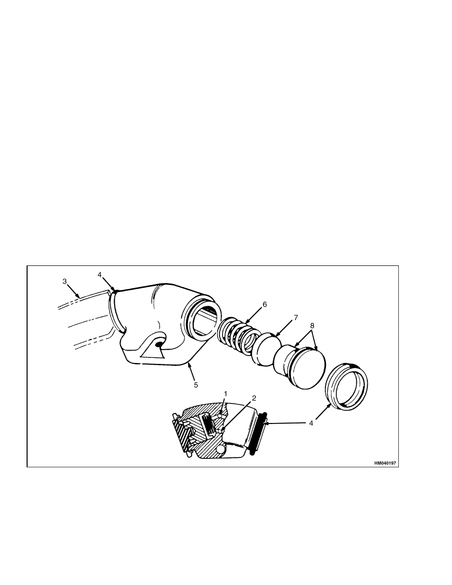
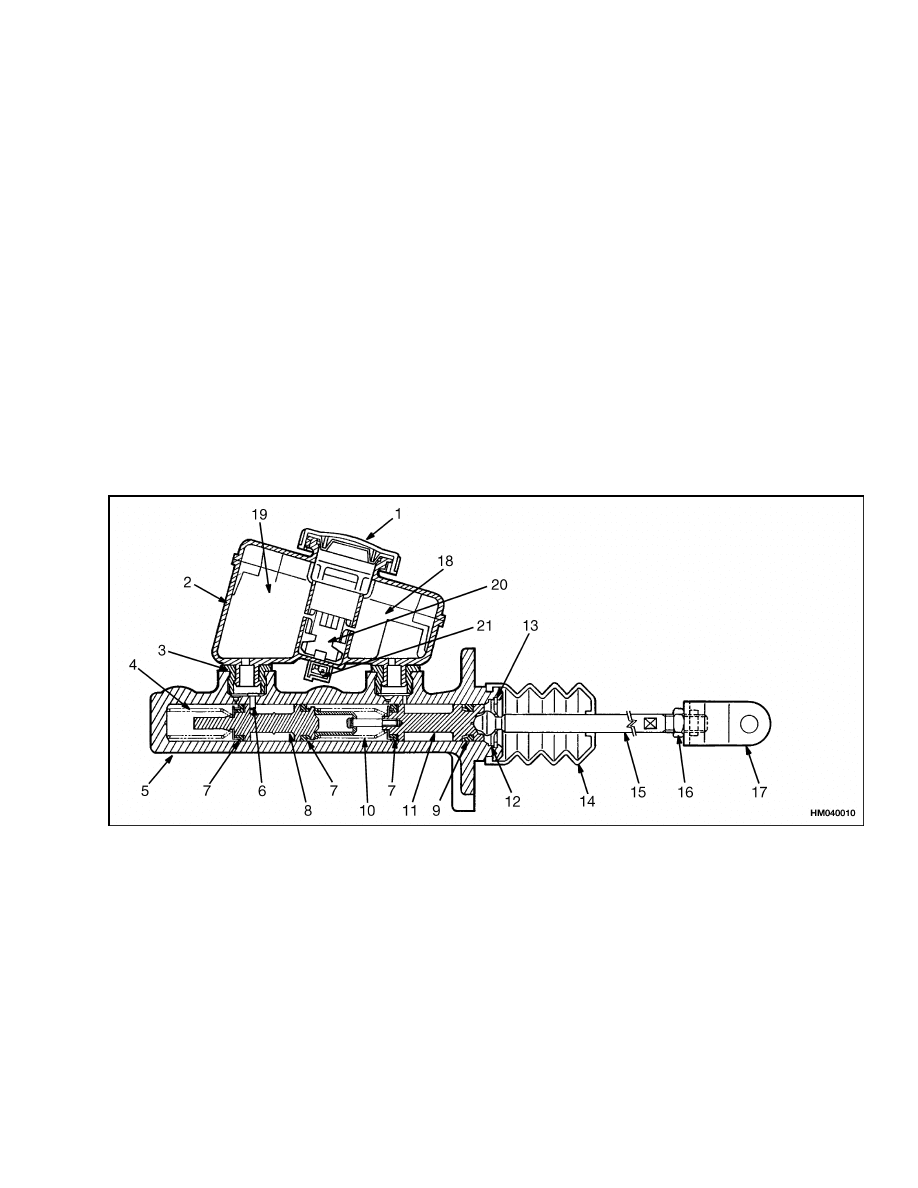
Master Cylinder Repair
REMOVE
1.
Remove floor plates from lift truck for access to
master cylinder. See Figure 11.
2.
Loosen and remove two brake hydraulic lines
from master cylinder. Disconnect wire at switch
on reservoir.
3.
Remove cotter pin, washer, and pin from push
rod end that is attached to brake linkage lever
arm.
4.
Remove capscrews, washers, and nuts that hold
master cylinder to bracket assembly and remove
master cylinder from lift truck.
1.
CAP
2.
RESERVOIR
3.
SEAL
4.
RETURN SPRING
5.
BODY
6.
PIN
7.
SEAL
8.
SECONDARY PISTON
9.
SEAL
10. SPRING
11. PRIMARY PISTON
12. WASHER
13. RETAINER RING
14. DUST COVER
15. ROD
16. LOCK NUT
17. CLEVIS
18. PRIMARY FLUID CHAMBER
19. SECONDARY FLUID CHAMBER
20. FLOAT
21. SWITCH (FLUID LEVEL)
Figure 11. Master Cylinder
13
Master Cylinder Repair
1800 SRM 566
CLEAN AND INSPECT
CAUTION
Do not use an oil solvent to clean the master
cylinder, wheel cylinder, or the brake linings.
Use a solvent approved for cleaning of brake
parts. Do not permit oil or grease in the brake
fluid or on the linings.
Inspect bore of master cylinder for holes or scratches.
Replace master cylinder assembly if there is damage.
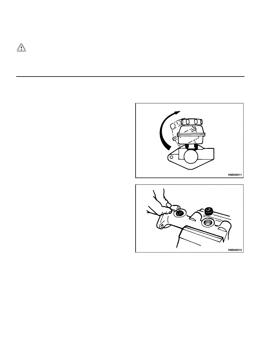
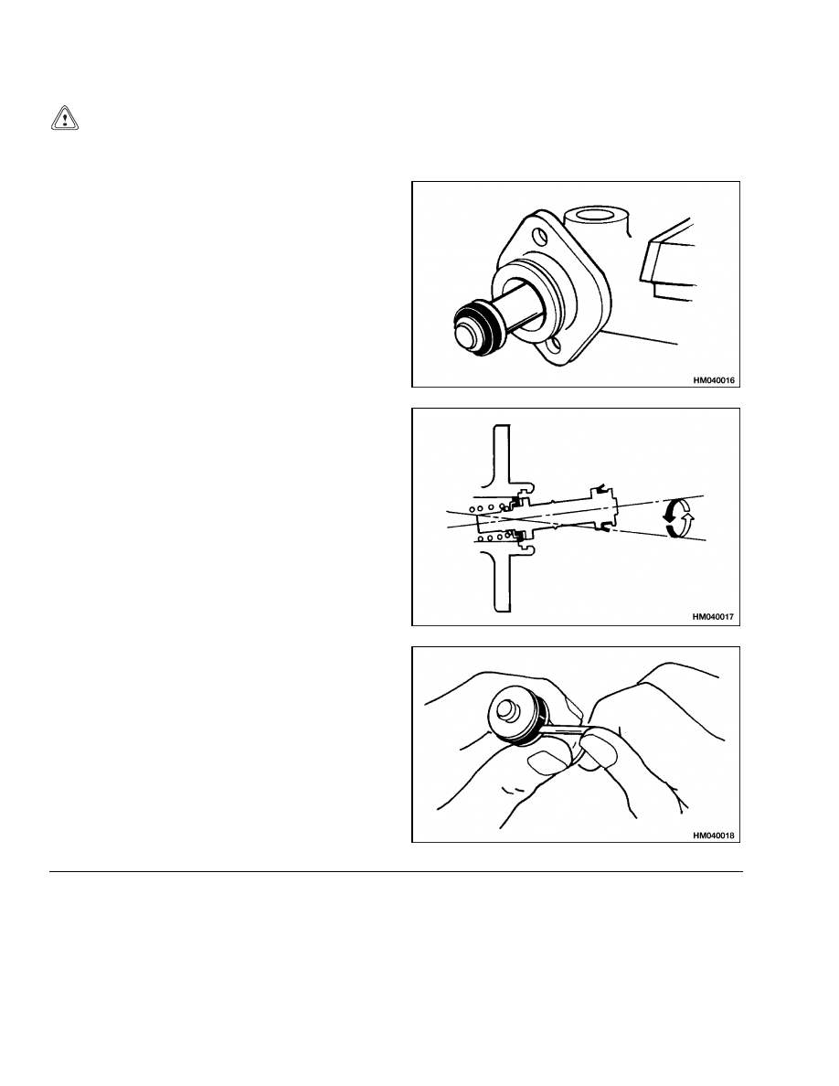
REPAIR
Repair master cylinder as follows:
STEP 1.
Remove fluid reservoir. Apply force in direction of ar-
row and pull reservoir from master cylinder. Install
reservoir by pushing and turning reservoir in oppo-
site direction. Make sure brake fluid does not leak
from reservoir seals. If there is any leakage, replace
seals.
STEP 2.
Be careful to not scratch the surfaces. Use a tool
(screwdriver with flat tip) that has a smooth and
rounded end to remove reservoir seals. Always in-
stall new seals. Put new seals in clean brake fluid;
then, install seals in body of master cylinder.
14
1800 SRM 566
Master Cylinder Repair
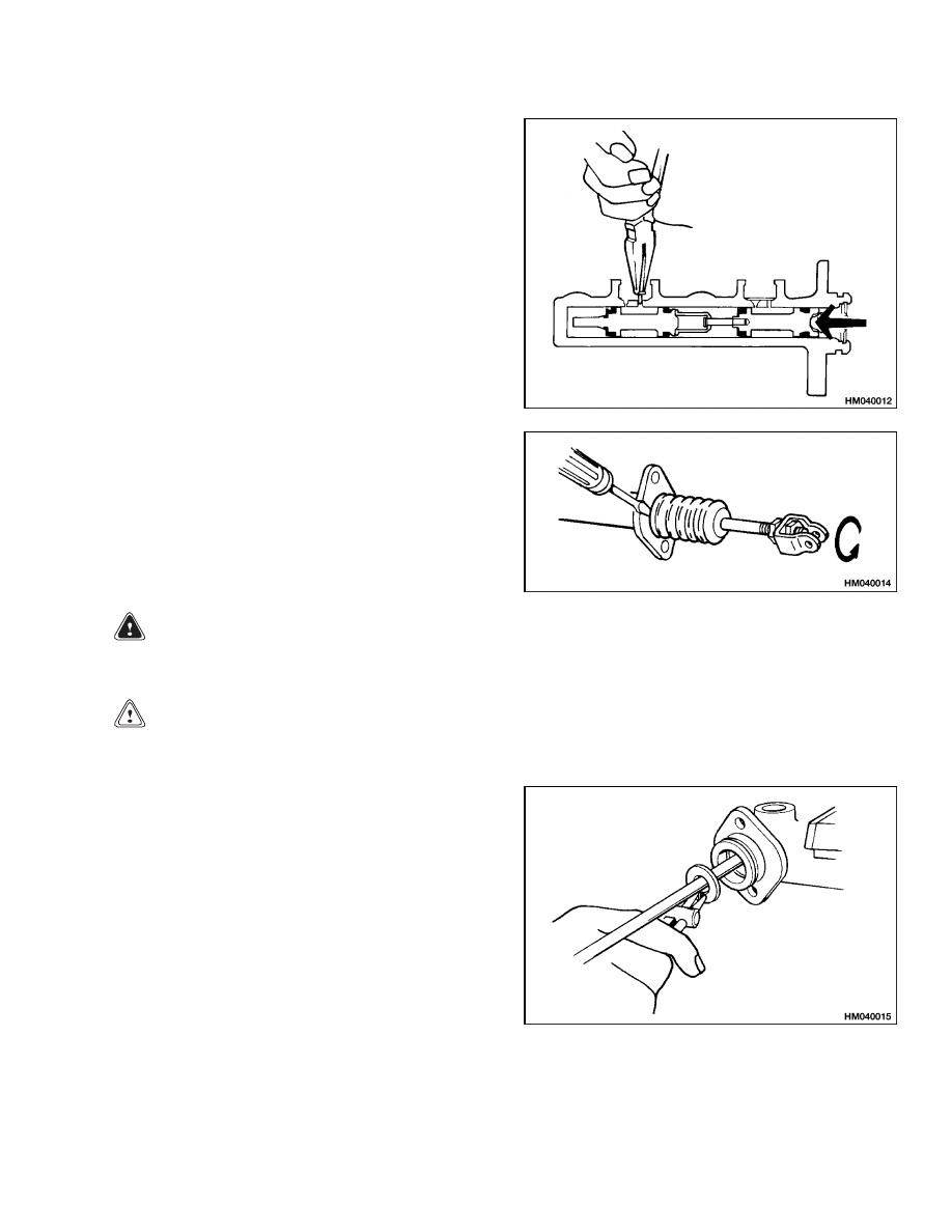
STEP 3.
Push primary piston into bore as shown in the illus-
tration. Remove pin at secondary piston through port
for secondary reservoir. Use the same method to in-
stall pin during assembly.
STEP 4.
Remove clevis and nut from push rod. Remove dust
cover. Be sure to put lip of dust cover into recess in
bore of cylinder during assembly.
WARNING
Keep control of the pistons as they are removed so that the return springs do not suddenly release
the pistons from the bore with enough force to cause an injury.
CAUTION
When the piston is removed or installed, make sure the cylinder bore or piston is not scratched or
damaged.
STEP 5.
Remove snap ring and primary piston assembly.
15
Master Cylinder Repair
1800 SRM 566
CAUTION
During disassembly and assembly of the primary and secondary pistons assembly, make sure not
to scratch or damage the cylinder bore when the spring is removed.
STEP 6.
Hit cylinder lightly on a soft or wooden surface and
remove secondary piston assembly. Lubricate cylin-
der bore with clean brake fluid to help removal.
STEP 7.
During installation of secondary piston, insert piston
assembly into cylinder until seal is at center of bore
opening. Be careful to not cause a restriction of seal
during installation. To make sure seal enters bore
correctly, carefully rotate and tilt piston until seal is
installed in bore. Slowly push piston assembly into
bore in one continuous motion after seal fully enters
bore.
NOTE: Install new seal when master cylinder is dis-
assembled for repair.
STEP 8.
Remove seal from piston with a smooth and rounded
tool.
INSTALL
Use the reverse order of Remove to install the mas-
ter cylinder. Check adjustment of brake pedal as de-
scribed in Brake Pedal Adjustment. See Figure 11.
16

1800 SRM 566
Brake System Air Removal
Service Brakes Adjustment
The following procedure is for newly installed brake
shoes. If the lift truck has been operated for more
than 25 hours and has correct pedal height, the
brakes normally will not need adjustment.
1.
See the procedure How To Put Lift Truck On
Blocks in the Periodic Maintenance section of
the service manual or the Operating Manual.
Put lift truck on blocks so drive wheels can be re-
moved. Remove drive wheels.
2.
Use an adjuster tool to rotate adjuster wheel so
teeth of wheel move downward. This adjustment
expands the brake shoes. Adjust brake shoes so
brake drum will not rotate.
3.
Push automatic adjuster lever away from ad-
juster wheel with a small screwdriver.
Use
adjuster tool to loosen adjuster wheel approxi-
mately 15 teeth (new brake shoes).
NOTE: If the brake shoes were not replaced, loosen
adjuster wheel approximately 15 teeth.
4.
Install drive wheels.
Remove lift truck from
blocks. Operate lift truck in FORWARD and
REVERSE directions. Stop lift truck 10 times
in each direction. This procedure causes brake
shoes to wear a small amount and fit the brake
drum better.
Brake Pedal Adjustment
Adjust pedal height to 95 mm (3.7 in.) by turning capscrew at rear of pedal assembly. This measurement is
made with the pedal pad mounted on the pedal. Make sure lock nut is tight. See Figure 9.
Master Cylinder Adjustment
Loosen lock nut on push rod. Turn push rod until
all of the clearance is removed between push rod and
master cylinder. Turn push rod 1/8 of a turn counter-
clockwise (viewed from the rear of the fork lift). This
will create the proper clearance, which will allow the
piston in the master cylinder to fully return when the
brake pedal is released. Make sure lock nut is tight.
See Figure 9.
Brake System Air Removal
Adjust the service brakes before the air is removed
from the brake system.
1.
Fill the master cylinder reservoir with brake
fluid.
2.
Put one end of a rubber hose on the special fitting
of the wheel cylinder. Put the other end of the
hose into a clear container of brake fluid.
3.
Loosen the special fitting at the wheel cylinder
one turn so that the air can be removed from the
brake system. Slowly push the brake pedal and
hold it at the end of its stroke. Close the special
fitting.
4.
Repeat the procedure in Step 1 through Step 3
until there are no air bubbles in the container.
5.
Check the level of the brake fluid in the reser-
voir for the master cylinder during the procedure.
Make sure to keep the brake fluid at the correct
level.
6.
Repeat the procedure for the other wheel cylin-
der. If there is still air in the system, the air
must be removed from the master cylinder. Push
on the brake pedal with a steady stroke. Release
the pedal slowly. Repeat this procedure until no
air bubbles enter the reservoir.
17

Troubleshooting
1800 SRM 566
Parking Brake Not Applied Switch Test
The "Parking Brake Not Applied" system is actuated
by a combination of two switches, one attached to the
parking brake mechanism and the other is the seat
switch. These switches actuate an audible buzzer
on the instrument cluster. When the operator leaves
the seat for more than two seconds without applying
the parking brake, the buzzer will be on continuously
for 10 seconds. The buzzer operates whether the key
switch is ON or OFF.
Torque Specifications
Back Plate to Axle Mount Capscrews
5/8 in. Capscrews 245 N•m (181 lbf ft)
1/2 in. Capscrews 125 N•m (92 lbf ft)
Wheel Cylinder Capscrews
7/16 in. Capscrews 78 to 91 N•m (58 to 67 lbf ft)
1/2 in. Capscrews 91 to 102 N•m (67 to 75 lbf ft)
Axle Shaft Capscrews
98 N•m (72 lbf ft)
Wheel Nuts
237 to 305 N•m (175 to 225 lbf ft)
Hub Nut
Inital: 205 N•m (151 lbf ft)
Final: 34 N•m (25 lbf ft)
Troubleshooting
PROBLEM
POSSIBLE CAUSE
PROCEDURE OR ACTION
The brakes do not correctly
stop the lift truck.
Air in the brake system.
Repair system to prevent air enter-
ing. Remove air from system.
The mount for the master cylinder is
loose.
Tighten fasteners.
The brake shoes are worn or dam-
aged.
Install new brake shoes.
The linings are too hard.
Install new, correct lining.
A brake drum is cracked.
Install new part.
A backplate is damaged.
Install new part.
A wheel cylinder is leaking or does
not operate correctly.
Repair or install new parts. Remove
air from system.
The brake linings do not fit the brake
drums.
Install correct linings.
Machine
brake drums.
The master cylinder is damaged.
Install new master cylinder. Remove
air from system.
Water or oil is on the brake linings.
Clean or install new linings.
18

1800 SRM 566
Troubleshooting
PROBLEM
POSSIBLE CAUSE
PROCEDURE OR ACTION
One brake does not release.
A brake shoe is damaged.
Install new parts.
A return spring is wrong.
Install new, correct spring.
The brake lines have a restriction.
Remove restriction or install new
lines. Remove air from system.
A parking brake cable is damaged or
needs adjustment.
Adjust cable or install new parts.
The wheel cylinder is damaged.
Repair or install new parts. Remove
air from system.
The backplate is worn or damaged.
Repair or install new parts.
The brakes make too much
noise.
Dirt, oil, water, or brake fluid is on
the linings.
Clean or install new linings.
The brake linings are worn.
Install new linings.
The brake drum is damaged.
Repair or install new brake drum.
A brake shoe is worn or damaged.
Install new brake shoe(s).
The brakes do not operate
equally.
Oil or brake fluid is on the linings.
Repair leak. Clean or install new lin-
ings.
The linings are worn or hard.
Install new linings.
A wheel cylinder is leaking.
Repair or install new parts. Remove
air from system.
The brake linings are not correctly
installed.
Install brake linings correctly.
The backplate or brake shoes are
damaged.
Repair or install new parts.
The brake drums are not round.
Check to make sure there is adequate
material to allow for machining. Ma-
chine brake drums to make them
round or install new drums.
The shoes are adjusted too tight.
Adjust brakes. Check self-adjusters.
19

Troubleshooting
1800 SRM 566
PROBLEM
POSSIBLE CAUSE
PROCEDURE OR ACTION
Both brakes do not release.
The parking brake is not released.
Release parking brake.
The parking brake cables need ad-
justment.
Adjust or install new cables.
There is not enough clearance at the
end of the push rod in the master
cylinder.
Adjust the clearance between push
rod and piston.
The master cylinder is damaged.
Install new master cylinder. Remove
air from system.
The brake shoes are adjusted too
tight.
Check operation of self-adjusters.
Adjust brakes.
The brake pedal travels too
far.
Air in the brake system.
Remove air from system. Check for
leaks.
Brake fluid level low. The brake sys-
tem has a leak.
Fill brake fluid reservoir to correct
level. Repair leak. Remove air from
system.
The brake shoes are not adjusted cor-
rectly.
Check operation of self-adjusters.
Adjust brakes.
The brake linings are worn.
Install new linings.
One of the dual brake circuits is not
operating.
Repair or install new parts.
There is too much clearance at the
end of the push rod in the master
cylinder.
Adjust the clearance between push
rod and piston.
The master cylinder is worn or dam-
aged.
Repair or install new master cylin-
der. Remove air from system.
The parking brake will not
hold the lift truck.
Parking brake not adjusted correctly.
Use adjustment knob on parking
brake lever to adjust holding force.
See adjustment procedure for correct
specifications.
Oil, water, or brake fluid is on the lin-
ings.
Clean or install new linings.
The parking brake cables need ad-
justment, lubrication, or have dam-
age.
Install new parts. Lubricate and ad-
just cables.
20

1800 SRM 566
Troubleshooting
PROBLEM
POSSIBLE CAUSE
PROCEDURE OR ACTION
The parking brake will not
release.
The parking brake lever is adjusted
too tight.
Adjust parking brake.
See adjust-
ment procedure for correct specifica-
tions.
The parking brake cables need ad-
justment, lubrication, or have dam-
age.
Install new parts. Lubricate and ad-
just cables.
21

NOTES
____________________________________________________________
____________________________________________________________
____________________________________________________________
____________________________________________________________
____________________________________________________________
____________________________________________________________
____________________________________________________________
____________________________________________________________
____________________________________________________________
____________________________________________________________
____________________________________________________________
____________________________________________________________
____________________________________________________________
____________________________________________________________
____________________________________________________________
____________________________________________________________
____________________________________________________________
____________________________________________________________
____________________________________________________________
____________________________________________________________
22


TECHNICAL PUBLICATIONS
1800 SRM 566
4/05 (3/03)(3/95) Printed in United Kingdom
Document Outline
- toc
- Brake System
- Safety Precautions Maintenance and Repair
- General
- Description and Operation
- Service Brake Repairs
- Parking Brake Repair
- Master Cylinder Repair
- Service Brakes Adjustment
- Brake Pedal Adjustment
- Master Cylinder Adjustment
- Brake System Air Removal
- Parking Brake Not Applied Switch Test
- Torque Specifications
- Troubleshooting
Wyszukiwarka
Podobne podstrony:
1510466 1800SRM0985 (05 2005) UK EN
1565789 1800SRM1117 (08 2005) UK EN
897670 1400SRM0575 (04 2005) UK EN
1565582 1600SRM1114 (04 2005) UK EN
897433 1800SRM0472 (04 1992) UK EN
1529749 1800SRM1036 (08 2005) UK EN
1531815 1800SRM1040 (03 2005) UK EN
1466229 1800SRM0734 (05 2005) UK EN
897097 1600SRM0316 (04 2005) UK EN
1463744 2200SRM0739 (04 2005) UK EN
1531821 1800SRM1037 (03 2005) UK EN
więcej podobnych podstron