

Rhapsody
®
Java Tutorial
Before using the information in this manual, be sure to read the “Notices” section of
the Help or the PDF available from Help > List of Books.

ii
This edition applies to Telelogic Rhapsody 7.4 and to all subsequent releases and modifications
until otherwise indicated in new editions.
© Copyright IBM Corporation 1997, 2008.
US Government Users Restricted Rights—Use, duplication or disclosure restricted by GSA ADP
Schedule Contract with IBM Corp.

Rhapsody
iii
Contents
Lesson 2: Creating an Object Model Diagram . . . . . . . . . . . . . . . . . . . . . . . . . . 13

Table of Contents
iv
Java Tutorial
Lesson 4: Creating a Console User Interface . . . . . . . . . . . . . . . . . . . . . . . . . . 25
Lesson 5: Creating Sequence Diagrams . . . . . . . . . . . . . . . . . . . . . . . . . . . . . . 31
Lesson 7: Generating Code, Building and Running your Application . . . . . . 39

Rhapsody
1
Lesson 1: Creating a Use Case Diagram
Use case diagrams (UCDs) show the main functions of the system (use cases) and the entities that
are outside the system (actors). Use case diagrams allow you to specify the requirements for the
system and show the interactions between the system and external actors.
Goals of this Lesson
In this lesson, you are going to determine who are the users of the system and what are the
requirements for the embedded system. Then you are going to create the Dishwasher use case
diagram.
Since this is the first lesson in the tutorial, you will first have to create a new Rhapsody project.
Creating a Rhapsody Project
To create the Rhapsody project you will be using for the tutorial, carry out the following steps:
1. Launch Rhapsody (Start > Programs > Telelogic > Telelogic Rhapsody > Rhapsody
Development Edition > Rhapsody in J).
2. Click the New button
on the main toolbar or select File > New. The New Project
dialog box opens.
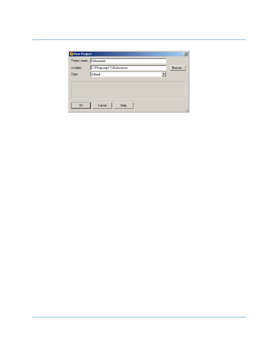
3. In the Project name box, replace the default project name with
Dishwasher
.
4. In the In folder box, browse to find an existing folder or enter a new folder name.
Note:
To avoid overwriting the sample Dishwasher project provided with the
Rhapsody product, do not create your project in
<Rhapsody
installation>\Samples\JavaSamples
. Also, to avoid potentially long
pathnames, it is recommended that you don’t create the project on the desktop.
5. In the Type box, accept Default, which provides all of the basic UML structures. It is
useful for most Rhapsody projects. Your dialog box should resemble the following figure:
Lesson 1: Creating a Use Case Diagram
2
Java Tutorial
Note:
For a description of the available project types that you can select from the
Type drop-down list, refer to the Rhapsody User Guide. (Do a search of the
user guide PDF file for “specialized profile.”)
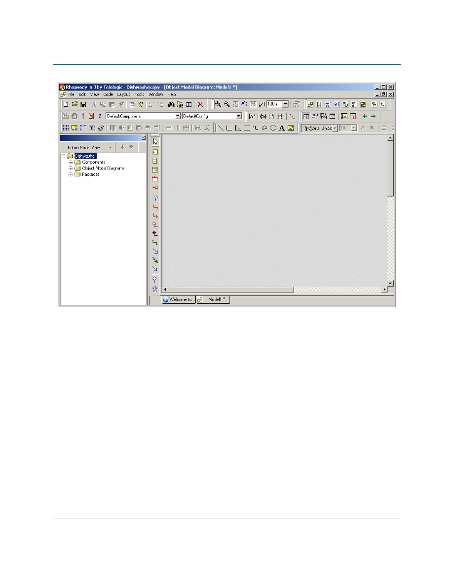
6. Click OK. If the specified location does not exist, Rhapsody asks whether you want to
create it. Click Yes.
Rhapsody creates your project in the new Dishwasher subfolder, opens the project, and
displays the Rhapsody browser in the left pane and the drawing area for an object model
diagram, as shown in the following figure.
Creating a Rhapsody Project
Rhapsody
3

Lesson 1: Creating a Use Case Diagram
4
Java Tutorial
Creating a Standard Java Project Structure
As can be seen in the tree in the Rhapsody Browser, project elements are contained in Packages. In
Rhapsody in J, these packages correspond to Java code packages when code is generated.
It is therefore recommended that you create a package structure in the browser in accordance with
standard Java practice.
1. In the Rhapsody browser, right-click the Packages category, and select Add New
Package from the context menu.
2. Name the new package
com
.
3. Right-click the
com
package, and select Add New > Package from the context menu.
4. Name the new package
telelogic
.
5. Repeat the previous two steps to create a package called
dishwasher
under the
telelogic
project.

Analyzing the Dishwasher System
Rhapsody
5
Analyzing the Dishwasher System
Before using Rhapsody, you should determine the requirements for the embedded system. To
analyze the dishwasher system used in this tutorial, answer these questions:
Who might use the system?
How they might use it?
What are the major actions of the system?
When do these actions occur?
What are the relationships, similarities, or differences between the actions?
What is standard behavior?
What can go wrong?
Some simplified answers to these questions might be as follows:
The system users or “actors” would include a “user” and a “service person.”
The system washes, rinses, and then dries dishes.
The “user” loads the dishes into the dishwasher, starts the dishwasher, and removes dishes
after they are washed.
The system may fail to wash, rinse, or dry the dishes and require service.
During this analysis phase, you identify actors for the system. The three types of actors to consider
are:
Users of the system
External components providing information to the system
External components receiving information from the system
Lesson 1: Creating a Use Case Diagram
6
Java Tutorial
Creating a Use Case Diagram
In this exercise you are going to create a use case diagram for the dishwasher system. A use case
diagram shows typical interactions between the system being designed and the external actors who
might interact with it.
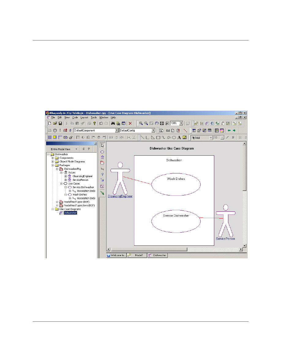
The following figure shows the Dishwasher use case diagram that you are going to create in this
exercise.
Dishwasher Use Case Diagram
To create the use case diagram, carry out the following steps:
1. Right-click the
dishwasher
package in the Rhapsody browser, and select Add New > Use
Case Diagram to open the New Diagram dialog box.
2. When the New Diagram dialog box is displayed, type
Dishwasher
as the name of the
diagram, and then click OK.
Rhapsody automatically adds the Use Case Diagrams category and the name of the new
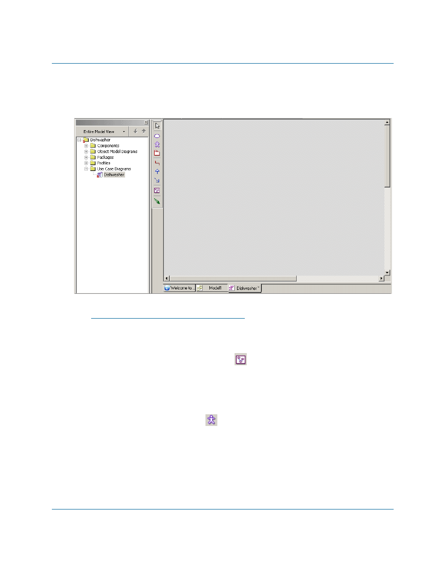
Creating a Use Case Diagram
Rhapsody
7
diagram to the Rhapsody browser and opens the new diagram in the drawing area, as
shown in the following figure:
Note
You can also create a diagram by using the Tools menu or the Diagrams toolbar. Also, once
you create a diagram you can open it using the Diagrams toolbar. Refer to the Rhapsody
User Guide for more information.
3. Click the Create Boundary box button
on the Drawing toolbar.
4. Click the drawing area and drag to create a boundary box. Rhapsody creates a boundary
box named
System Boundary Box
.
5. Rename the boundary box
Dishwasher
and then press Enter.
6. Click the Create Actor button
on the Drawing toolbar.
7. On the drawing area, click to the left side of the boundary box. Rhapsody creates an actor
with a default name.
8. Rename the actor
User
and then press Enter.
Note:
Because code can be generated using the specified names, do not include
spaces in the names of actors.

Lesson 1: Creating a Use Case Diagram
8
Java Tutorial
9. Draw another actor outside the boundary box named
ServicePerson
.
10. In the browser, you will see a category called
Actors
under the
dishwasher
package. If
you expand
Actors
, you will see the two actors that you just created.
Note:
To quickly find the actors in the Rhapsody browser, right-click an actor on the
use case diagram and click Locate or press Ctrl+L. You can use this technique
with other objects on a diagram as well.
Adding Use Cases to the Diagram
During the analysis phase, you identified user-visible functions or important goals of the system.
These are use cases. A use case represents a particular function of the system. To draw the use
cases, follow these steps:
1. Click the Create Use Case button
on the Drawing toolbar.
2. Click inside the top half of the boundary box. Rhapsody creates a use case with a default
name.
3. Rename the use case
Wash Dishes
and then press Enter.
Note:
For use case names, you can use spaces because use case names do not appear
in generated code.
4. Create another use case inside the boundary box named
Service Dishwasher
.
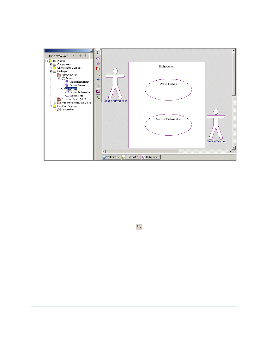
5. In the browser, you can expand the Use Cases category to view the use cases you created,
as shown in the following figure:
Associating Actors with Use Cases
Rhapsody
9
Associating Actors with Use Cases
The User washes dishes and configures the washing mode, while the ServicePerson only services
the dishwasher as needed.
To incorporate the relationships of the actors to the use cases into the design, you draw association
lines between the actors and use cases. An association represents a connection between objects or
users.To draw association lines, follow these steps:
1. Click the Create Association button
on the Drawing toolbar.
Notice that once you move your cursor over the drawing area the mouse pointer turns into
a crosshairs pointer to signify that it is enabled and that it changes into a circled crosshairs
pointer when drawing is possible.
2. Click the edge of the User actor and then click the edge of the Wash Dishes use case.
Rhapsody creates an association line with the name label highlighted. You do not need to
name this association, so click the mouse button again (this is the same as pressing
Enter).
Note:
To keep a line straight as you draw it, press the Ctrl key as you are drawing the
line.

Lesson 1: Creating a Use Case Diagram
10
Java Tutorial
3. Create an association between the ServicePerson actor and the Service Dishwasher use
case and then click the mouse button again or press Enter.
4. Click the Save button
to save your model.
Your use case diagram should resemble the following figure:
Adding a Diagram Title
Each diagram has its name in the diagram table and in the title bar of the window that displays the
diagram. However, it is also useful to add a title onto the diagram itself to help other members of
your team understand the content and purpose of a diagram.
To add an optional title to your diagram, follow these steps:
1. With the diagram displayed in the drawing area, click
on the Free Shapes toolbar.
2. Click above the system boundary box in the diagram and type, for example,
Dishwasher
Use Case Diagram
, and press Ctrl+Enter.
Note:
If you press Enter, you move your cursor to a new line. In this case, to exit
typing mode, you have to press Ctrl+Enter to end your action. Or you can
click out of the typing area.
Summary
Rhapsody
11
3. Make the following changes if you want:
a. Reposition the title by dragging it into another location.
b. Use the tools on the Format toolbar to change the font styles.
4. Click the Save button
to save your model.
For more information about the Free Shapes and Format toolbars, refer to the Rhapsody User
Guide.
Summary
In this lesson, you determined who are the users of the system and what are the requirements for
the embedded system. Then you created a use case diagram that shows the functions and
requirements of the dishwasher. You became familiar with the parts of a use case diagram and
created the following:
System boundary box
Actors
Use cases
Association lines
Title for your diagram
You are now ready to proceed to the next lesson, where you are going to define how the system
components are interconnected using an object model diagram.

Lesson 1: Creating a Use Case Diagram
12
Java Tutorial

Rhapsody
13
Lesson 2: Creating an Object Model
Diagram
Object model diagrams (OMDs) specify the types of objects in the system, the attributes and
operations that belong to those objects, the static relationship that can exist between classes
(types), and the constraints that may apply. The Rhapsody code generator directly translates the
elements and relationships modeled in OMDs into Java source code.
Goals for this Lesson
In this lesson, you are going to create an object model diagram that shows how the system
components are interconnected.
In this lesson, you are going to:
Create an object model diagram
Create classes in the object model diagram
Add attributes to a class
Add operations to a class
Lesson 2: Creating an Object Model Diagram
14
Java Tutorial
Creating an Object Model Diagram
To create the object model diagram, follow these steps:
1. Start Rhapsody and open the Dishwasher model you created if they are not already open.
2. In the browser, right
-
click the
dishwasher
package and then select Add New > Object
Model Diagram.
3. When the New Diagram dialog box is displayed, type
Dishwasher
and then click OK.
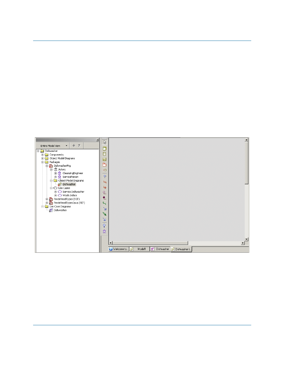
Rhapsody adds the Object Model Diagrams category underneath the
dishwasher
package, and
adds the name of the new object model diagram to the browser. Rhapsody also opens the new
object model diagram in the drawing area, as shown in the following figure:
Adding Classes and Objects to the Diagram
Rhapsody
15
Adding Classes and Objects to the Diagram
1. Click the Class button
on the Drawing toolbar.
Notice that once you move your mouse pointer over the drawing area, a class icon appears
along with it.
2. Click-and-drag on the drawing area and create a tall rectangular class.
3. Rename the class
Dishwasher
and then press Enter.
4. Select the
Dishwasher
class and change to Structured view by clicking the Specification/
Structured View button
on the toolbar.
5. Click the Object button
on the Drawing toolbar, and use it to draw an object inside
the
Dishwasher
class. For the name, type
jet:Jet
. Click
Yes
when you are asked
whether you want to create a class called Jet. This will create an object called jet based on
a class called Jet.
6. Using the Object button again, draw another object inside the
Dishwasher
class and name
it
heater:Heater
. This will create an object called heater based on a class called Heater.
Note:
The
jet
and
heater
objects were only created here to illustrate the creation of
parts in a class. They will not be referred to in the tutorial.
7. Select the
Dishwasher
class and change it back to Specification view by clicking the
Specification/Structured View button a second time.
8. Right-click the
Dishwasher
class to open the context menu, and select Display Options...
9. On the General tab, click the Compartments... button.
10. In the Available list, select Part, and then click << Display to add it to the Displayed
list. (Verify that Attributes and Operations are also in the Displayed list.)
11. Click OK.
12. Click OK to close the Display Options dialog box. You should now see the objects you
created displayed in a compartment.
13. Create another class beside the
Dishwasher
class and name it
Display
.
Adding Attributes and Operations to a Class
1. In the object model diagram you created, right-click the Dishwasher class to display the
context menu.

Lesson 2: Creating an Object Model Diagram
16
Java Tutorial
2. Select New Attribute.
3. Name the attribute
washTime
.
4. Repeat the previous steps to create another two attributes called
rinseTime
and
dryTime
.
5. Right-click the Dishwasher class to display the context menu, and select Features...
6. On the Attributes tab of the Features dialog box, you should see the three attributes you
created. Verify that they have
Public
visibility and are of type
int
. If not, use the drop-
down lists to modify the visibility and/or type.
7. Click OK to close the Features dialog box.
8. Right-click the Dishwasher class to display the context menu, and select New Operation.
Name the operation
setup
.
9. Right-click the Dishwasher class to display the context menu, and select Features...
10. On the Operations tab of the Features dialog box, double-click the
setup
operation.
This will open the Features dialog box for the operation.
11. On the Implementation tab, type in the following Java code:
washTime = 5000;
rinseTime = 4000;
dryTime = 5000;
12. Click OK to close the Features dialog box for the
setup
operation.
13. Click OK to close the Features dialog box for the
Dishwasher
class.
14. Save your project.
Summary
In this lesson, you created an object model diagram that specified the types of objects in the system
and the attributes and operations that belong to those objects.
You are now ready to proceed to the next lesson, where you will create a statechart for the
Dishwasher
class.

Rhapsody
17
Lesson 3: Creating a Statechart
Statecharts define the behavior of objects, including the various states that an object can enter over
its lifetime and the messages or events that cause it to transition from one state to another. Each
statechart defines the life cycle behavior of a single reactive class. Therefore, a single reactive
class can be associated with only one statechart.
Goals for this Lesson
In this lesson you will learn to perform the following tasks:
Draw a statechart
Draw states and nested states
Draw transitions
Specify entry and exit actions
Draw history connectors
Lesson 3: Creating a Statechart
18
Java Tutorial
Creating a Statechart
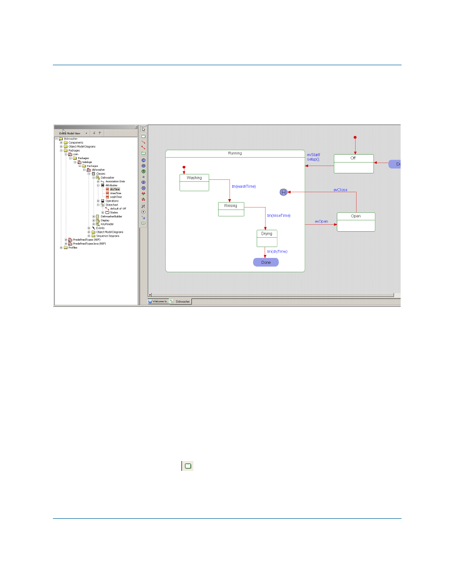
The following figure shows the Dishwasher statechart that you are going to create in this exercise.
To create a statechart, follow these steps:
1. Start Rhapsody and the Dishwasher model if they are not already open.
2. In the Rhapsody browser, right-click the Dishwasher class.
3. Select Add New > Statechart.
Rhapsody automatically adds the new statechart under the Dishwasher class in the
browser. In addition, Rhapsody opens the new statechart in the drawing area.
Adding States to a Statechart
To draw a state, follow these steps:
1. Click the State button
in the Drawing toolbar.
2. Click-and-drag on the drawing area to create a large state, and name the state
Running
.
Adding States to a Statechart
Rhapsody
19
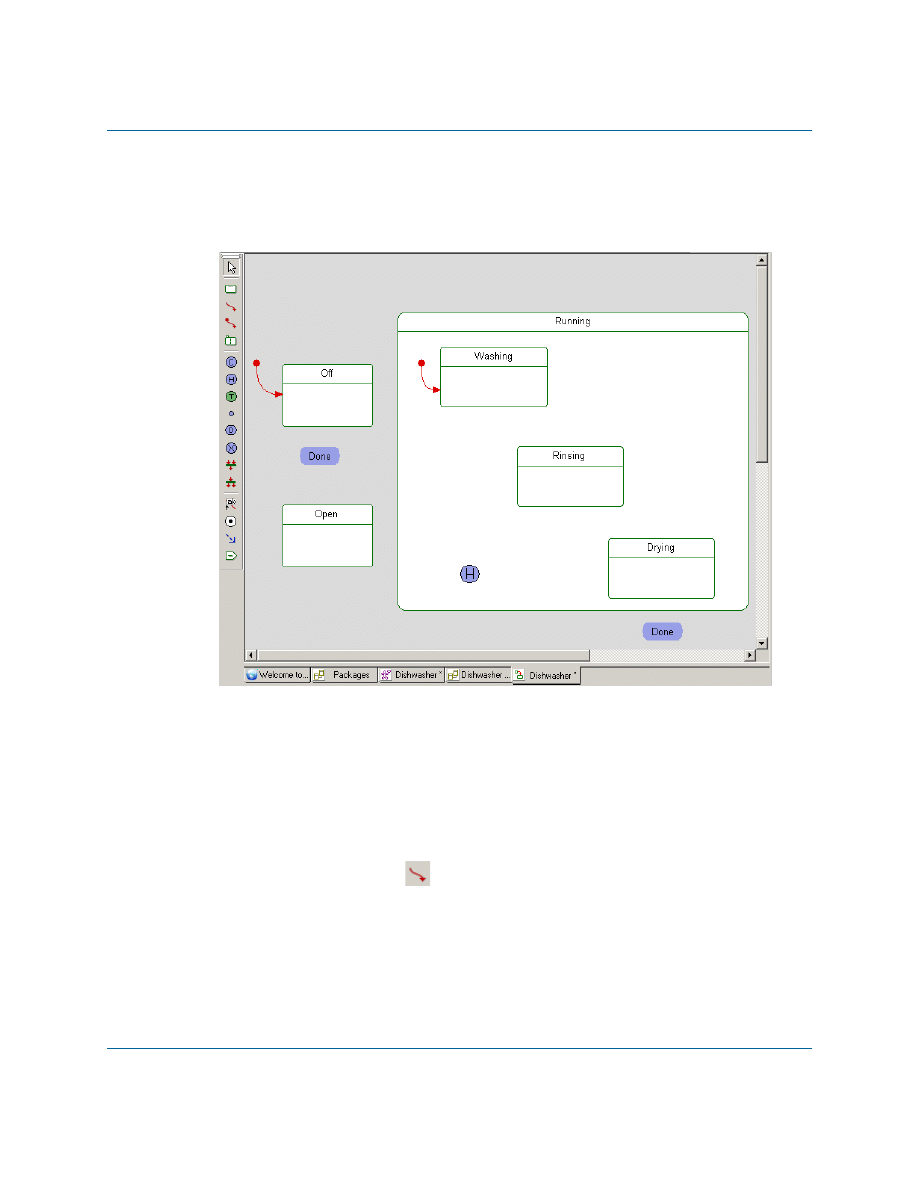
3. Using the completed statechart screen capture as a reference, draw the following states
inside the Running state:
– Washing
– Rinsing
– Drying
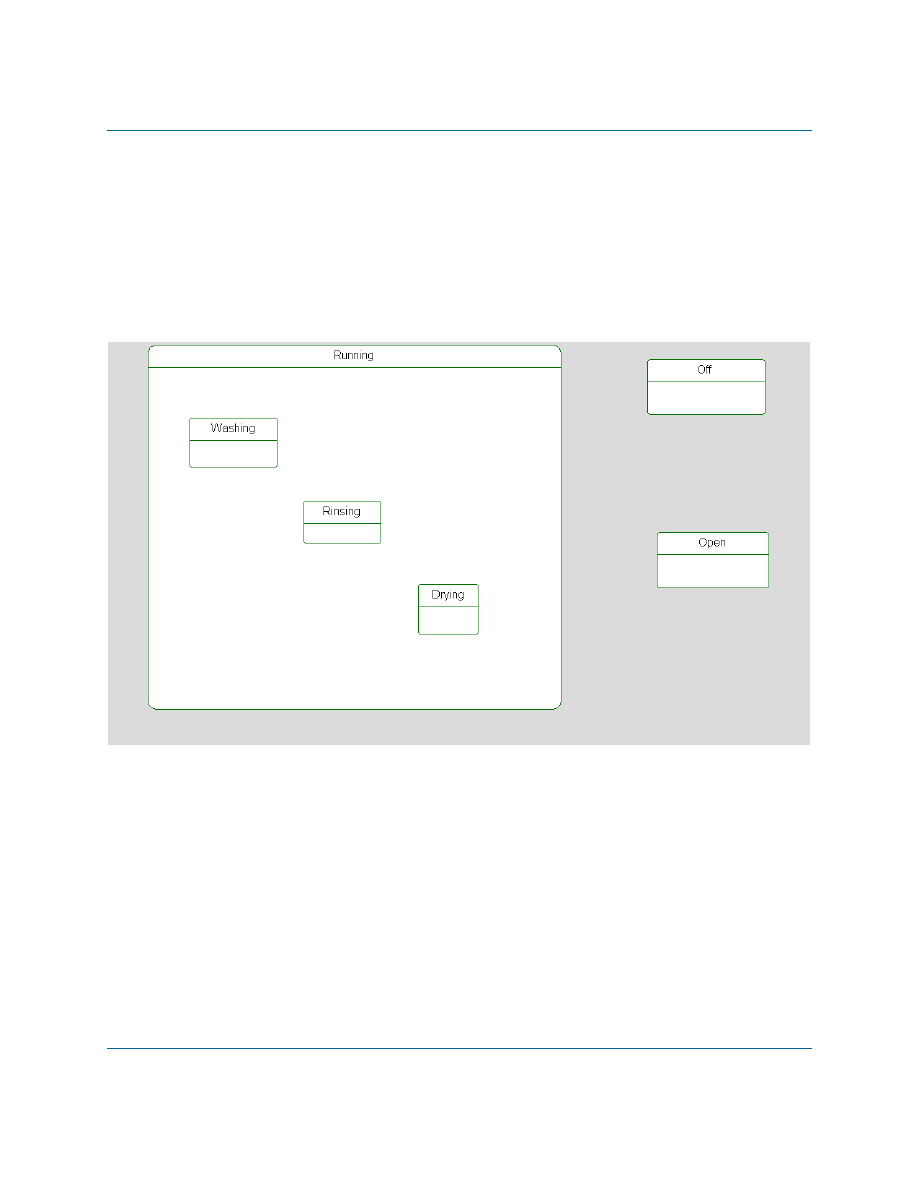
4. Outside the Running state, draw two more states and name them
Off
and
Open
.
Your statechart should resemble the following figure:
Lesson 3: Creating a Statechart
20
Java Tutorial
Drawing History and Diagram Connectors
If you open and close the door during operation, the dishwasher must start up again where it left
off in the wash cycle. In other words, you want the dishwasher to save its history so it can continue
where it left off after an interruption. History connectors store the most recent active configuration
of a state. A transition to a history connector restores this configuration.
When the dishwasher is done drying, the cycle should start over again at the beginning, to handle
future loads. To define the cycle restart, use diagram connectors to connect the end of one part of a
statechart to the beginning of another part. These connectors physically join distant transition
segments. Diagram connectors have the same name to indicate they are a pair of connectors. This
tells the system to jump from one to the other even if they are located on different statecharts.
To draw these connectors, follow these steps:
1. Click the History connector button
on the Drawing toolbar and then click inside the
Running state.
2. Click the Diagram connector button
on the Drawing toolbar and create the
following diagram connectors and label them
Done
in the following locations:
– Inside the
Running
state, below the
Drying
state. This is the source diagram
connector.
– Outside the
Running
state, next to the
Off
state. This is the target connector.
3. Save your model.
Drawing Default Connectors
One object must be assigned the default state. In the default state, the object knows to start the
system. When the dishwasher first starts, it is in the
Off
state.
Note that once you have drawn a default connector in a statechart, Rhapsody does not allow you to
draw another one in the same chart. Each object can have only one default state.
To assign the default states for classes in the statechart, follow these steps:
1. Click the Default connector button
on the Drawing toolbar.
2. Click in the drawing area above and away from the
Off
state, then click an edge of the
Off
state, and then click away from the connector to skip naming the connector (or press
Ctrl+Enter).
Drawing Transitions
Rhapsody
21
3. Use the same method to draw a default connector to the Washing state, keeping the
connector inside the Running state.
At this point, your statechart should resemble the following figure:
Drawing Transitions
A transition represents a message or event that causes an object to switch from one state to
another.
To add transitions, use the following steps:
1. Click the Transition button
on the Drawing toolbar.
2. Click an edge of the Off state to anchor the start of the transition and then click an edge of
the Running state to anchor the end of the transition.
3. Type
evStart/setup();
as the label and then press Ctrl+Enter to dismiss the edit box.
(Pressing Enter only adds a new line.)
Lesson 3: Creating a Statechart
22
Java Tutorial
Note:
To change the text of a label or add a label to a previously drawn transition,
click the Transition Label
on the Drawing toolbar. Click the transition
line and type/edit label text.
4. Draw a transition from the
Running
state to the
Open
state and type
evOpen
as the label.
5. Draw a transition from the
Open
state to the
H
history connector and type
evClose
as the
label.
6. Inside the
Running
state, draw a transition from the
Washing
state to the
Rinsing
state and
label it
tm(washTime)
.
Note:
tm
represents a timeout.
7. Draw a transition from the
Rinsing
state to the
Drying
state and label it
tm(rinseTime)
.
8. Draw a transition from
Drying
state to the
Done
diagram connector and label it
tm(dryTime)
.
9. Draw an unlabeled transition from the
Done
target diagram connector to the
Off
state.
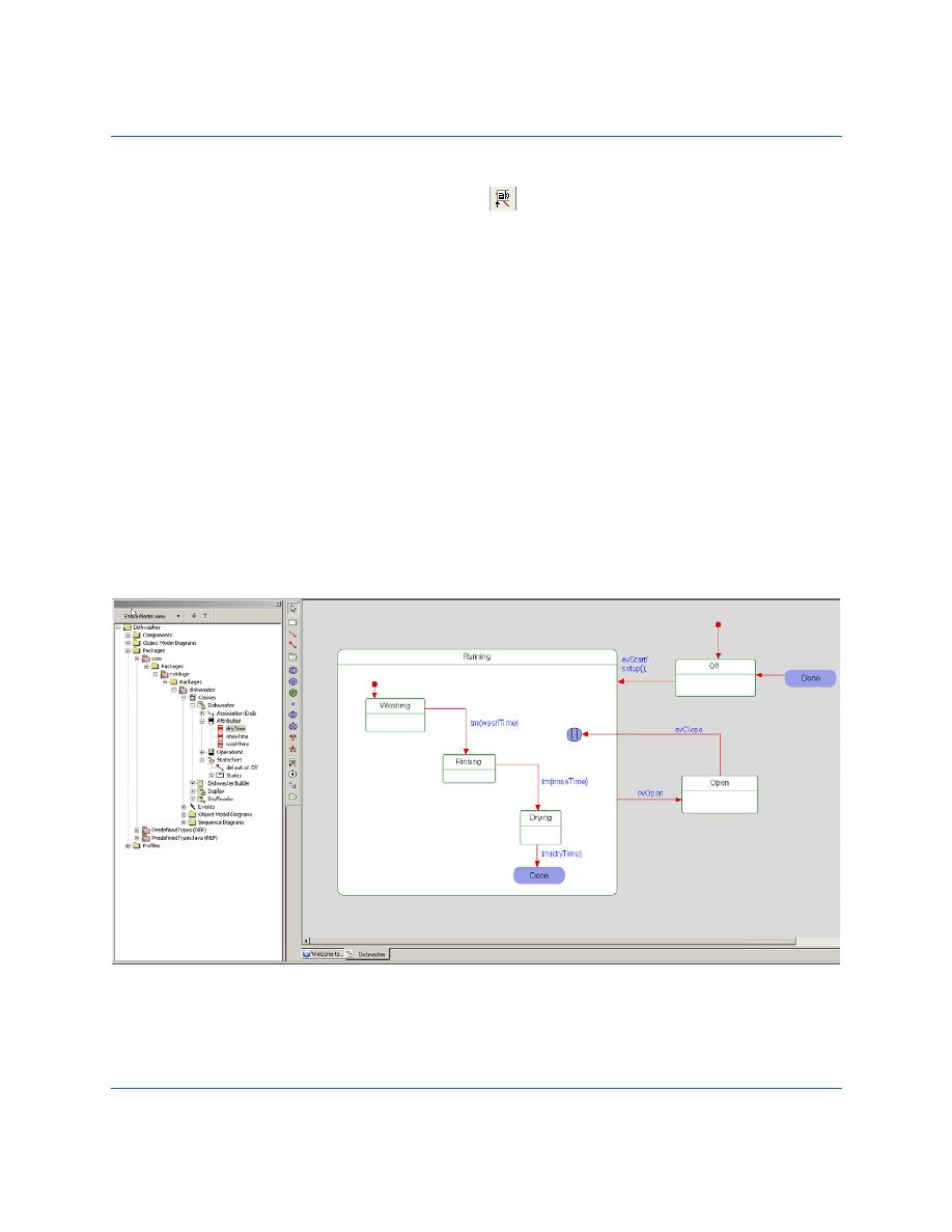
At this point, your statechart should shows the Dishwasher with all of the transitions
between the various states, and your diagram should resemble the following figure:
Adding Actions to States
Rhapsody
23
Adding Actions to States
To define actions that should be carried out upon entry into a state or exit from a state, follow these
steps:
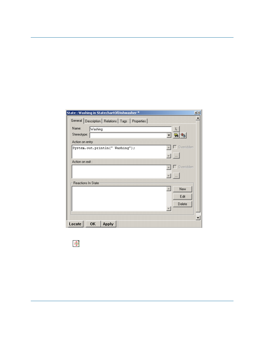
1. Double-click the
Washing
state on the statechart to open the Features dialog box.
2. On the General tab, type the following code in the Action on entry box, as shown in the
following figure:
System.out.println("Washing");
3. Click OK to apply your changes. On the statechart, notice that the
Washing
state has an
icon
in the upper right corner. This indicates that the
Washing
state now has
underlying actions.
4. Double-click the
Rinsing
state, and type the following code in the Action on entry box,
and click OK:
System.out.println("Rinsing");

Lesson 3: Creating a Statechart
24
Java Tutorial
5. Double-click the
Drying
state, and type the following:
a. In the Action on entry box:
System.out.println("Drying");
b. In the Action on exit box:
System.out.println("Dishwasher Cycle Complete");
6. For the Open state, type the following:
a. In the Action on entry box:
System.out.println("Door Opened");
b. In the Action on exit box:
System.out.println("Door Closed");
7. Save your model.
Summary
In this lesson, you created a statechart, which identifies the state
-
based behavior for your
dishwasher model. You became familiar with the parts of a statechart and created the following:
States and nested states
Default connectors
Transitions
Actions
You are now ready to proceed to the next lesson, where you will create a simple console interface
that will allow you to control the basic functions of the dishwasher.

Rhapsody
25
Lesson 4: Creating a Console User
Interface
In this lesson, you will create the elements necessary to allow you to use input from a command
line to input events connected to the operation of the dishwasher. Specifically, you will
create a new class called KeyReader
add a statechart for the Display class
add additional operations and parts to the Display class
create an activity diagram for the KeyReader class
Create the KeyReader Class
The following steps will create a new class that will be responsible for reading the input provided
by the user in the command-line.
1. Right-click the dishwasher package to open the context menu, and select Add New >
Class.
2. Name the class
KeyReader
.
3. In the browser, double-click the
KeyReader
class to open up the Features dialog box.
4. On the General tab, set Concurrency to
active
.
Add a Statechart for the Display Class
The following steps will create a statechart that specifies the behavior of the Display class when
different events are sent from the command-line.
1. In the browser, right-click the
Display
class to open the context menu, and select Add
New > Statechart.
2. Add a state called
WaitForKeys
to the statechart.
3. Draw a default transition leading to the
WaitForKeys
state.
4. Add a condition connector to the diagram.
Lesson 4: Creating a Console User Interface
26
Java Tutorial
5. Draw a transition from
WaitForKeys
to the condition connector and label it
evKeyPress
.
6. Open the Features dialog box for the
evKeyPress
event.
7. Go to the Arguments tab, and click <New> to create a new argument called
key
.
8. Use the drop-down list to set the argument type to
char
.
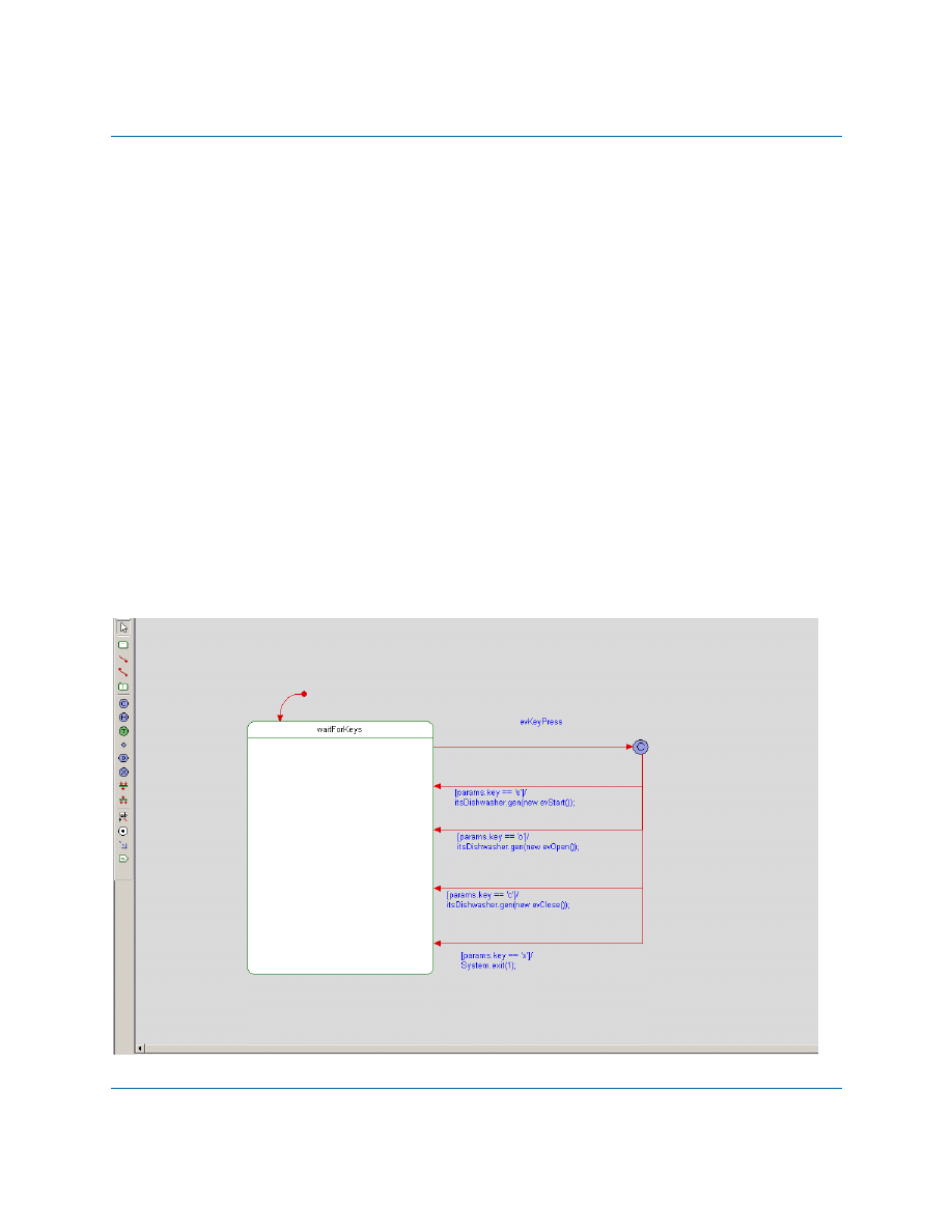
9. Draw a transition from the condition connector to the
WaitForKeys
state and enter the
following label:
[params.key == 's']/itsDishwasher.gen(new evStart());
10. Draw another transition from the condition connector to the
WaitForKeys
state and enter
the following label:
[params.key == 'o']/itsDishwasher.gen(new evOpen());
11. Draw another transition from the condition connector to the
WaitForKeys
state and enter
the following label:
[params.key == 'c']/itsDishwasher.gen(new evClose());
12. Draw another transition from the condition connector to the
WaitForKeys
state and enter
the following label:
[params.key == 'x']/System.exit(1);
Your statechart should now look like the following:

Add Part/Operation to Display Class
Rhapsody
27
Add Part/Operation to Display Class
The following steps will establish the relationship between the Display class and the new
KeyReader class that you created.
1. In the browser, right-click the
Display
class to open the context menu, and select Add
New > Part. When the list of available classes is displayed, select KeyReader from the
list.
2. Press Enter to accept the default name provided for the new part,
itsKeyReader
.
3. Double-click the part you created (
itsKeyReader
) to open the Features dialog box.
4. On the General tab, in the section Relation to whole, check knows Display as and enter
itsDisplay
.
5. Click OK to apply the changes.
6. In the browser, double-click the
Display
class to open the Features dialog box.
7. Go to the Operations tab, click <New>, and then select Primitive Operation from the
list displayed to create a new operation, and name it
processKey
.
8. Double-click the name of the operation you created to open the Features dialog box for
processKey
.
9. Go to the Arguments tab, and click <New> to create an argument called
key
of type char.
10. Click OK to apply the changes.
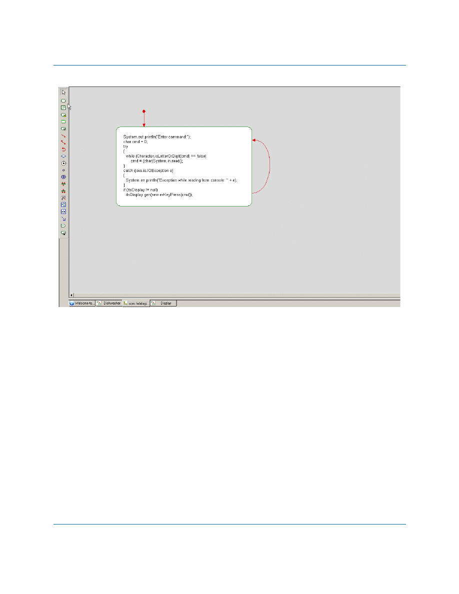
Create an Activity Diagram for the KeyReader Class
The following steps will create an activity diagram that specifies the behavior for the KeyReader
class to allow it to take the user input and initiate the event that the Display class waits for.
1. In the browser, right-click the
KeyReader
class to open the context menu, and select Add
New > Activity Diagram. The new diagram will be opened in the drawing area.
2. Use the Action tool on the Drawing toolbar to add an action to the activity diagram.
3. Enter the following code in the Action box for the action you created:
System.out.println("Enter command:");
4. Use the Default Flow tool to draw a default flow leading to the action you added.
5. Use the Action tool on the Drawing toolbar to add a second action to the activity diagram.

Lesson 4: Creating a Console User Interface
28
Java Tutorial
6. Use the Activity Flow tool to add an activity flow from the first action you added to the
second action you added.
7. Enter the following code in the Action box for the second action you created:
char cmd = 0;
try
{
while (Character.isLetterOrDigit(cmd) == false)
cmd = (char)System.in.read();
}
catch (java.io.IOException e)
{
System.err.println("Exception while reading from console: " + e);
}
if (itsDisplay != null)
itsDisplay.gen(new evKeyPress(cmd));
8. Use the Activity Flow tool to add an activity flow from the second action you added,
leading back to itself.
Your activity diagram should now look like the following:
Summary
Rhapsody
29
Summary
In this lesson, you
created a new class called KeyReader to handle the user input
added a statechart for the Display class to specify its behavior when different events are
sent from the command-line
added a part based on the KeyReader class to establish the relationship between the
Display class and the KeyReader class
created an activity diagram that specified how the KeyReader class should respond to
input entered by the user
In the next lesson, you will construct a sequence diagram that shows how the various elements of
the system communicate with one another over time.

Lesson 4: Creating a Console User Interface
30
Java Tutorial

Rhapsody
31
Lesson 5: Creating Sequence Diagrams
Sequence diagrams show structural elements communicating with one another over time. They
also identify required relationships and messages. A high-level sequence diagram shows the
interactions between actors, use cases, and blocks. Lower-level sequence diagrams show
communication between classes and objects.
Sequence diagrams have an executable aspect and are a key application animation tool. When you
animate the model to see the application’s operations, Rhapsody dynamically builds sequence
diagrams that record the object-to-object or block-to-block messaging.
Goals for this Lesson
In this lesson you will learn to perform the following tasks:
Draw a sequence diagram
Lesson 5: Creating Sequence Diagrams
32
Java Tutorial
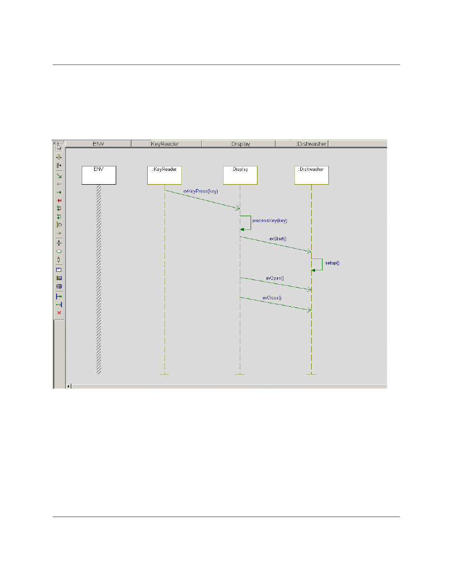
Creating the Execution Sequence Diagram
The following figure shows the Execution sequence diagram that you are going to create in this
exercise.
Execution Sequence Diagram
Rhapsody separates sequence diagrams into a Names pane and a Message pane. The Names pane
contains the name of each instance line or classifier role. The Message pane contains the elements
that make up the interaction.
To create a new sequence diagram, follow these steps:
1. In the Rhapsody browser, right-click the
dishwasher
package, and select Add New >
Sequence Diagram.
2. When the New Diagram dialog box is displayed:
Creating the Execution Sequence Diagram
Rhapsody
33
a. Name the diagram Execution
b. Select the Design option
c. Click OK.
3. Click the System Border button
on the Drawing toolbar and click on your sequence
diagram. Rhapsody creates an item named ENV (for environment) that represents the
system border.
4. Drag the
KeyReader
class from the Rhapsody browser to the right of the system border.
5. Drag the
Display
class from the browser to the right of the
KeyReader
line that you
added.
6. Drag the
Dishwasher
class from the browser to the right of the
Display
line.
7. Using the Message button
on the Drawing toolbar, draw a diagonal message from the
KeyReader
class to the
Display
class, and then open the context menu for the message
and select Select Message > evKeyPress.
8. Using the Message button once again, draw a message from the
Display
line back to the
Display
line (message to self) below the previous message, and then open the context
menu for the message and select Select Message > processKey.
9. Draw a diagonal message from the
Display
line to the
Dishwasher
line, below the
previous message, and then open the context menu for the message and select Select
Message > evStart.
10. Draw another message to self, this time on the
Dishwasher
line, below the previous
message, and then open the context menu for the message and select Select Message >
setup.
11. Draw a diagonal message from the
Display
line to the
Dishwasher
line, below the
previous message, and then open the context menu for the message and select Select
Message > evOpen.
12. Draw a diagonal message from the
Display
line to the
Dishwasher
line, below the
previous message, and then open the context menu for the message and select Select
Message > evClose.
13. Save your model.

Lesson 5: Creating Sequence Diagrams
34
Java Tutorial
Summary
In this lesson, you created a sequence diagram, which show structural elements communicating
with one another over time for your dishwasher model. You became familiar with the parts of a
sequence diagram and created the following:
System border
Classifier roles
Workflow with messages and events.
You are now ready to proceed to the next lesson, where you are going to build an additional object
model diagram that will represent the objects created during execution of the application.
Rhapsody
35
Lesson 6: Creating Objects
In this lesson, you construct an object model diagram that represents the objects that are created
when you run the application.
You will also learn to specify the features of a Rhapsody configuration, which represents the
details of how you want an application to be built.
Creating the Build Object Model Diagram
To construct an object model diagram that represents the objects that are to be created when the
application is run, follow these steps:
1. Right-click the
dishwasher
package in the browser, and select Add New > Object Model
Diagram. Name the diagram
Build
.
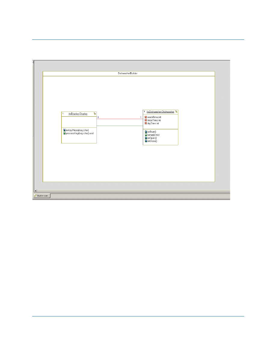
2. Using the Composite Class tool
in the Drawing toolbar, add a large composite class
called
DishwasherBuilder
to the diagram.
3. Drag the
Display
and
Dishwasher
classes from the browser into the new composite class
that you created.
4. Right-click the
Display
class to display the context menu, and select Make an Object.
5. Right-click the
Dishwasher
class to display the context menu, and select Make an
Object.
6. Using the Association tool
in the Drawing toolbar, draw an association between
Display
and
Dishwasher
.
7. Using the Link tool
in the Drawing toolbar, draw a link between
Display
and
Dishwasher
.
Note:
Links represent instances of an association.
Lesson 6: Creating Objects
36
Java Tutorial
At this point, your object model diagram should resemble the following figure:
Specifying the Features of a Rhapsody Configuration
To specify how Rhapsody should build the executable for your application, follow these steps:
1. In the Rhapsody browser, open the Components category.
2. Select the component named DefaultComponent, press F2, and rename the component
EXE
.
3. Double-click the
EXE
component to open its Features dialog box.
4. On the Scope tab of the Features dialog box, select the All Elements option.
5. In the browser, under the
EXE
component, open the Configurations category.
6. Select the configuration DefaultConfig, press F2, and rename the configuration
Host
.
7. Double-click the
Host
configuration to open its Features dialog box.

Summary
Rhapsody
37
8. On the Settings tab of the Features dialog box, set the Instrumentation Mode to
Animation.
9. On the Initialization tab, choose the Explicit option under Initial Instances, and then
open the tree of elements and select the check box for
DishwasherBuilder
.
10. Save the model.
Summary
In this lesson, you:
created an object model diagram that represents the objects that are created when you run
the application
modified the settings of a Rhapsody configuration to instruct Rhapsody how it should
build the executable for your application

Lesson 6: Creating Objects
38
Java Tutorial

Rhapsody
39
Lesson 7: Generating Code, Building and
Running your Application
In this lesson, you will:
Generate Java code for your model
Build your application from your model
Run your application using Rhapsody’s animation feature
Generating Code from the Model
Your model can contain more than one component. In turn, each component can contain a number
of configurations.
When you generate code with Rhapsody, it generates code for the active configuration of the active
component. In the Rhapsody browser, the active component and configuration are displayed in
bold.
The active component and configuration are also displayed in the Code toolbar.
In the model built in this tutorial, there is only a single component with a single configuration. So
in this case, you do not have to concern yourself with making sure these are the active component/
configuration before generating code. Keep in mind that when working with models with multiple
components/configurations, you have to check that the correct component and configuration are
designated as active before you generate code.
Note
To make a component/configuration active, you can open the context menu for the
component/configuration and select Set as Active. Alternatively, you can select the
component and configuration from the drop-down lists that are included in the Code toolbar.
1. Select Code > Generate > Host. Rhapsody displays a message that the output directory
for the Host configuration does not yet exist and asks you to confirm its creation.
2. Click Yes. Rhapsody places the source files generated in the new
Host
directory.
Lesson 7: Generating Code, Building and Running your Application
40
Java Tutorial
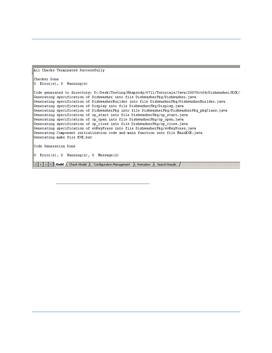
Rhapsody generates the code and displays output messages in the Log tab of the Output window,
as shown in the following figure:
Note
If the Output window is not visible at the bottom of the Rhapsody window, select View >
Output Window from the main menu.
The messages inform you of the code generation status, including:
Success or failure of internal checks for the correctness and completeness of your
model. These checks are performed before code generation begins.
Names of files generated for classes and packages in the configuration.
Names of files into which the main() function is generated.
Completion of code generation.
Fixing Code Generation Errors
If you receive code generation errors, double-click the error in the Output window to go to the
source of the error. The source of the error appears as a highlighted element. Once you fix the
problem, regenerate the code (choose Code > Re Generate > Host) until there are no error
messages.
Building an Application with Rhapsody
Rhapsody
41
Examining Generated Source Files
To view the code generated for a specific class, right-click on the class in the browser to open the
context menu and select Edit Code.
If you want to toggle the display of line numbers in the code, do the following:
1. Right-click in the code window and select Properties to open the Window Properties
dialog box.
2. On the Misc tab, in the Line Numbering area, select a numbering style from the drop-
down list (for example, Decimal).
3. Click OK.
Building an Application with Rhapsody
Once you generate code without any errors, you are ready to build the model.
To build the model, do one of the following:
Select Code > Build > Build Entire Project, or
Click the Make button
on the Code toolbar.
Build messages, including any compilation errors that may have occurred are displayed on the
Build tab of the Output Window.
If you encounter any compilation errors, double-clicking the error will take you to the problematic
model element or problematic code.
Running an Application with Animation
Now that the application has been built, you can run the application and use Rhapsody’s animation
feature to verify that the application runs correctly.
1. In the Rhapsody browser, double-click the
Execution
sequence diagram to open the
diagram.
2. To run the application, do one of the following:
a. Select Code > Run MainEXE.class, or
b. Click the Run Executable button
on the Code toolbar.

Lesson 7: Generating Code, Building and Running your Application
42
Java Tutorial
3. After the console window opens, return to the Rhapsody window. You will see that a
dynamic (animated) version of the
Execution
sequence diagram has been opened. At this
point, it will only display the various instance lines.
4. Click the Go button
on the Animation toolbar. You will see Create() messages in the
animated sequence diagram, representing the creation of the initial objects.
5. Right-click the
Dishwasher
instance line, and select Open Animated Statechart. A
dynamic (animated) version of the
Dishwasher
statechart will be opened.
6. Resize the console window that was opened when you ran the application and the
Rhapsody window so that you can align the windows side-by-side to see both at once.
7. Enter
s
in the console window and press Enter.
8. Watch the animated statechart as the application progresses through the various states that
you defined. The active state at any given moment is highlighted in magenta.
9. In order to simulate the opening of the dishwasher door, enter
s
in the console window and
press Enter, and immediately afterwards enter
o
in the console window and press Enter.
The application will move to the Open state in the statechart.
Note:
When we earlier defined the attributes that control the movement between the
Washing
,
Rinsing
, and
Drying
states, we used very small numbers (4-5
seconds). If you find that this does not give you enough time to enter the
character for simulating the door opening event, you can go to the
Implementation tab of the Features dialog box for the
setup
operation of the
Dishwasher
class and change the numbers. You will then have to regenerate
the code and rebuild the application before running the application (using the
Regenerate and Rebuild options in the Code menu).
10. Enter
c
in the console window and press Enter. The application will return to the
Running
state. Note that the application is able to return to the state where it was when the door
was opened because we used a History connector in the statechart.
11. Enter
x
in the console window and press Enter. The console window will close and the
application will stop running.
Injecting Events with the Animation Toolbar
In order to facilitate the simulation of events for our application, we included a console-based
control panel. While this was useful for the limited number of events in this application, it would
not be very convenient for a system with dozens of events.
Rhapsody provides an easy way to simulate all of the events you have defined for your application.
In this section, you will use this event-injection mechanism.
Injecting Events with the Animation Toolbar
Rhapsody
43
Note
Since it will probably take you a little while to get used to the GUI controls used in
Rhapsody for simulating events, it is recommended that you change the values for the
attributes that control the timing of movement between the
Washing
,
Rinsing
, and
Drying
states so that the application stays in the different states for a longer period.
1. In the Rhapsody browser, double-click the
Execution
sequence diagram to open the
diagram.
2. Run the application by doing one of the following:
a. Select Code > Run MainEXE.class, or
b. Click the Run Executable button
on the Code toolbar.
3. After the console window opens, return to the Rhapsody window. You will see that a
dynamic (animated) version of the
Execution
sequence diagram has been opened. At this
point, it will only display the various instance lines.
4. Click the Go button
on the Animation toolbar. You will see Create() messages in the
animated sequence diagram, representing the creation of the initial objects.
5. Right-click the
Dishwasher
instance line, and select Open Animated Statechart. A
dynamic (animated) version of the
Dishwasher
statechart will be opened.
6. Click the Event Generator button
on the Animation toolbar.
7. When the Events dialog is displayed, click the Select button and select
DishwasherBuilder[0]->itsDishwasher
from the list of instances.
8. From the drop-down list of events, select
evStart
.
9. Click OK.
10. Watch the animated statechart as the application progresses through the various states that
you defined. The active state at any given moment is highlighted in magenta.
11. Click the Event Generator button
on the Animation toolbar.
12. When the Events dialog is displayed, click the Select button and select
DishwasherBuilder[0]->itsDishwasher
from the list of instances.
13. From the drop-down list of events, select
evOpen
.
14. Click OK. The application will move to the Open state in the statechart.
15. Click the Event Generator button
on the Animation toolbar.
Lesson 7: Generating Code, Building and Running your Application
44
Java Tutorial
16. When the Events dialog is displayed, click the Select button and select
DishwasherBuilder[0]->itsDishwasher
from the list of instances.
17. From the drop-down list of events, select
evClose
.
18. Click OK. The application will return to the
Running
state. Note that the application is
able to return to the state where it was when the door was opened because we used a
History connector in the statechart.
19. Click the Stop Make/Execution button
on the Code toolbar. The application will
stop running.
Using Breakpoints with Animation
Rhapsody allows you to add breakpoints to stop execution at various points.
In the model we have been using in this tutorial, once the dishwashing cycle has started, the cycle
continues until completed. In this section, we will use a breakpoint to have the application stop
when it reaches the
Drying
state.
1. In the Rhapsody browser, double-click the
Execution
sequence diagram to open the
diagram.
2. Run the application by doing one of the following:
a. Select Code > Run MainEXE.class, or
b. Click the Run Executable button
on the Code toolbar.
3. After the console window opens, return to the Rhapsody window. You will see that a
dynamic (animated) version of the
Execution
sequence diagram has been opened. At this
point, it will only display the various instance lines.
4. Click the Go button
on the Animation toolbar. You will see Create() messages in the
animated sequence diagram, representing the creation of the initial objects.
5. Right-click the
Dishwasher
instance line, and select Open Animated Statechart. A
dynamic (animated) version of the
Dishwasher
statechart will be opened.
6. Click the Breakpoints button on the Animation toolbar.
7. When the Breakpoints dialog box is displayed, click New. The Define Breakpoint dialog
box is displayed.
8. Click Select, and choose
DishwasherBuilder[0]->itsDishwasher
from the list of
instances.
Summary
Rhapsody
45
9. From the Reason drop-down list, select State Entered.
10. In the Data field, enter
Drying
.
11. Click OK.
12. Click the Event Generator button
on the Animation toolbar.
13. When the Events dialog is displayed, click the Select button and select
DishwasherBuilder[0]->itsDishwasher
from the list of instances.
14. From the drop-down list of events, select
evStart
.
15. Click OK.
16. On the animated statechart you will see that the application progresses through the various
states, however, it stops after entering the
Drying
state. You will also see on the
Animation tab of the Output window a message indicating that a breakpoint was
reached.
17. To allow the application to resume, click the Go button
on the Animation toolbar.
Now, the dishwashing cycle will continue until completion.
18. Click the Stop Make/Execution button
on the Code toolbar. The application will
stop running.
Summary
In this lesson, you:
Generated Java code from the model.
Built the application.
Ran the application.
Ran the application with animation.
Injected events using the Animation toolbar
Used breakpoints with animation.
This completes the hands-on part of the tutorial. In the next lesson, you find a list of additional
Java-specific features provided by Rhapsody, as well as descriptions of many advanced features
that were not used in the framework of this tutorial.

Lesson 7: Generating Code, Building and Running your Application
46
Java Tutorial

Rhapsody
47
Additional Rhapsody Features
This section lists additional Java-specific features of Rhapsody that were not demonstrated in this
tutorial.
It also contains descriptions of key Rhapsody features that were not used in the tutorial.
Java-specific Features
Rhapsody includes the following Java-specific features that were not used in this tutorial. You can
find information on these features in the Rhapsody User Guide.
Java annotations
Java enums
Static import
Static blocks
Javadoc
Java reference model
Additional Rhapsody Features
The following are important features of Rhapsody that were not used in this tutorial. You can find
information on these features in the Rhapsody User Guide.
Reverse engineering
Rhapsody can analyze existing code and build a Rhapsody model based on the code.
Roundtripping
In addition to one-shot analysis of existing code, you can make manual changes to code
generated by Rhapsody and then have Rhapsody bring these changes into the model and
regenerate code from the updated model.
Model reports
Rhapsody includes a highly-configurable reporting tool called ReporterPLUS that you can
use to generate detailed reports from your model, including text and diagrams. When you

Additional Rhapsody Features
48
Java Tutorial
don’t need the flexibility provided by ReporterPLUS, you can use Rhapsody’s internal
report generator to create basic model reports.
Rhapsody API
Rhapsody provides an API that can be used to perform most Rhapsody actions from
within a script. Two versions of the API are provided: a COM-based API that can be used
with C++ or VB/VBA/VBScript, and a Java API that can be used to perform Rhapsody
actions from within a Java program.
Rhapsody command-line interface
A command-line version of Rhapsody is provided to allow you to easily perform
Rhapsody actions that do not require the GUI, for example, code generation. The
commands provided can be included in scripts in order to perform tasks such as nightly
builds.

Rhapsody
49
Index
A
Actions
Actors
Associations
B
Building the model
C
Code generation
debugging
Connectors
default
diagram
history
transitions
Creating
object model diagram
use case diagram
D
Debugging
Default connectors
Diagrams
Dishwasher use case diagram
Execution sequence diagram
object model
Dishwasher
object model diagram
use case diagram
Dishwasher statechart
Dishwasher use case diagram
Drawing
connectors
default connector
E
Execution sequence diagram
F
Files
code generation
G
Generated source files
H
History connectors
I
J
Java code examples
timeout framework method
M
Message pane
Model building
N
Names pane
O
Operations
Output window
P
Packages

In d e x
50
Java Tutorial
SubsystemsPkg
Panes
Message
Profiles
Project profiles
Project types
R
Rebuilding the application
Regenerating code
Requirements
Rhapsody
project profiles
project types
specialized profiles
S
instance area
Message pane
Names pane
set border
Source files
Statecharts
Dishwasher
transitions
States
adding actions
drawing
Synchronization
T
Transition connectors
Types of profiles
U
Use case diagrams
actors
Dishwasher
use cases
Use cases
Document Outline
- Contents
- Lesson 1: Creating a Use Case Diagram
- Lesson 2: Creating an Object Model Diagram
- Lesson 3: Creating a Statechart
- Lesson 4: Creating a Console User Interface
- Lesson 5: Creating Sequence Diagrams
- Lesson 6: Creating Objects
- Lesson 7: Generating Code, Building and Running your Application
- Additional Rhapsody Features
- Index
Wyszukiwarka
Podobne podstrony:
wsp z rodz
IO ALL
Knopek WSP Kraje egzotyczne tabela
io wyk5
18 Mit mityzacja mitologie wsp Nieznany (2)
bugzilla tutorial[1]
freeRadius AD tutorial
Alignmaster tutorial by PAV1007 Nieznany
free sap tutorial on goods reciept
ms excel tutorial 2013
Joomla Template Tutorial
gprs t6 io pl 1013
io 8 z
ALGORYTM, Tutoriale, Programowanie
Zestaw Fiz.wsp, AGH, ROK I, fizyka, Fizyka
UK+üAD WSP+ô+üCZULNY, Biologia II, Fizjologia zwierząt i człowieka
więcej podobnych podstron