
AIAA-2003-0696
1
ALTERNATIVE COMPOSITE MATERIALS FOR MEGAWATT-SCALE WIND TURBINE BLADES:
DESIGN CONSIDERATIONS AND RECOMMENDED TESTING
Dayton A. Griffin
Global Energy Concepts, LLC
5729 Lakeview Drive NE, Suite 100
Kirkland, WA 98033
Thomas D. Ashwill
Wind Energy Technology Department
Sandia National Laboratories
Albuquerque, NM 87185-0708
ABSTRACT
As part of the U.S. Department of Energy’s Wind
Partnerships for Advanced Component Technologies
program, Global Energy Concepts LLC (GEC) is
performing a study concerning blades for wind turbines
in the multi-megawatt range. Earlier in this project
constraints were identified to cost-effective scaling-up
of the current commercial blade designs and
manufacturing methods, and candidate innovations in
composite materials, manufacturing processes and
structural configurations were assessed. In the present
work, preliminary structural designs are developed for
hybrid carbon fiber / fiberglass blades at system ratings
of 3.0 and 5.0 megawatts. Structural performance is
evaluated for various arrangements of the carbon blade
spar. Critical performance aspects of the carbon
material and blade structure are discussed. To address
the technical uncertainties identified, recommendations
are made for new testing of composite coupons and
blade sub-structure
NOMENCLATURE
c
chord length (m)
Ex Longitudinal
modulus
(GPa)
Ey Transverse
modulus
(GPa)
GPa giga-Pascals
(10
9
N/m
2
)
Gxy shear
modulus
(GPa)
kW kilowatt
m meters
MW megawatt
R
rotor radius (m)
x/c
distance along chord
y/c
distance perpendicular to chord
ε
material strain (%)
ε
design
design value of material strain (%)
η
x,xy
shear strain coefficient
ν
xy
major Poisson’s ratio of laminate
υ
f
laminate fiber volume fraction
Copyright
2003 by the American Institute of Aeronautics
and Astronautics, Inc. and the American Society of
Mechanical Engineers. All Rights Reserved.
BACKGROUND
In recent years both the size of wind turbine blades and
the volume of commercial production has been steadily
increasing. Rotors of up to 80 m diameter are in current
production, and several turbine developers have
prototypes in the 100 to 120 m diameter range. It is
estimated that over 50 million kilograms of finished
fiberglass laminate were used for the production of
wind turbine blades in the year 2001, and that
worldwide production volume will increase for the next
several years (calculations based on the global wind
energy market predictions of Reference 1). As a result
of these growth trends, research programs in both the
United States and Europe have been investigating
alternative blade design and materials technologies.
In Europe, jointed blade designs are being evaluated for
their potential benefits in transportation and erection
costs, and carbon fiber composites are being
investigated for potential improvements in blade weight
and cost.
2-6
In the United States, the U.S. Department
of Energy is conducting the Wind Partnerships for
Advanced Component Technologies (WindPACT)
program. The purpose of the WindPACT program is to
explore the most advanced technologies available for
improving wind turbine reliability and decreasing the
cost of energy (COE).
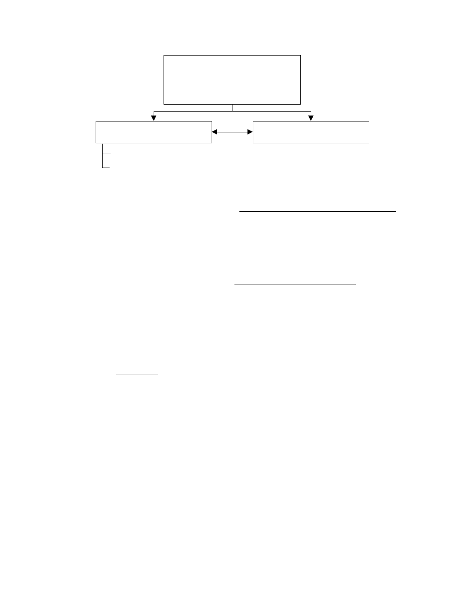
Figure 1 illustrates the relationship among the
WindPACT studies that concern the design and
manufacture of wind turbine blades. In the initial phase
of the program, scaling studies were performed in the
areas of turbine blades
7
, transportation and erection
logistics
8
, and self-erecting tower concepts.
9
The
purpose of the scaling studies is to determine optimum
sizes for future turbines, identify sizing limits for
critical components and technologies, and to investigate
the potential benefits from advanced concepts. Under
the NREL-sponsored Turbine Rotor Design Study,
extensive aeroelastic simulations are being performed
for a wide range of rotor sizes and configurations, and
the resulting loads are being used to quantify the impact
on turbine cost and COE.
10,11
2
Scaling Studies
- Rotor blades
- Transportation and erection logistics
- Self-erecting towers
- Balance of station costs
Sandia Blade System
Design Study (BSDS)
NREL Turbine Rotor
Design Study
BSDS Part 1 - Analytical
BSDS Part 2 - Composites testing
Figure 1 WindPACT studies concerning composite blade design and manufacture
Under the Sandia-sponsored Blade System Design
Studies (BSDS), alternative composite materials,
manufacturing processes and structural designs are
being evaluated for potential benefits for MW-scale
blades.
12
As indicted by Figure 1, the BSDS has two
parts. Part 1 is analytical, and involves trade-off
studies, selection of the most promising technologies,
development of design specifications and preliminary
design for MW-scale blades, identification of technical
issues for alternative materials and manufacturing
approaches, and development of recommendations for
materials testing. The Part 2 BSDS involves testing of
coupons and blade substructure with the objectives of
evaluating composite materials and resolving technical
issues identified in the Part 1 study. The content in this
paper focuses primarily on the latter stages of the Part 1
BSDS. Earlier work under this project is reported in
detail in Reference 12.
APPROACH
The material in this paper was developed from a large
number of sources. Throughout this project GEC
consulted with manufacturers of composites materials,
wind turbine blades, and turbine systems. The BSDS
has also benefited from extensive synergy with other
DOE-funded wind energy research efforts. The
Montana State University (MSU) Composites Research
Group collaborated substantially in the areas of material
properties and test development. Results from the
WindPACT Rotor Study were used to develop the
baseline blade structural configurations and loads for
the BSDS blade designs. GEC performed the majority
of the design calculations using the ANSYS finite
element analysis (FEA) code with the Sandia-developed
NuMAD interface.
13
The results, conclusions and
recommendations in this report reflect an integration of
all these diverse technical elements.
GENERAL ISSUES FOR MW-SCALE BLADES
This section reviews some of the major conclusions
from earlier work under the BSDS, and discusses
general issues concerning large blades. Specific
technical issues concerning blade composite materials
will be discussed following the development of the
preliminary 3.0 MW blade design.
Scaling of Conventional Blade Designs
Very few fundamental barriers have been identified for
the cost-effective scaling of the current commercial
blade designs and manufacturing methods over the size
range of 80 to 120 m diameter. The most substantial
constraint is transportation costs which rise sharply for
lengths above 46 m (150 ft) and become prohibitive for
long-haul of blades in excess of 61 m (200 ft).
In terms of manufacturing, it is expected that
environmental considerations will prohibit the
continued use of processes with high emissions of
volatile gasses, such as the open-mold wet lay-up that
has been the wind industry norm. Another
manufacturing concern for large blade is bonding
compounds. As blade sizes increase it is natural for the
gaps between fitted and bonded parts to grow as well.
However, the bonding materials used for smaller blades
do not scale well to increasing gap sizes, and blade
tooling and production costs for large blades increase
rapidly as dimensional tolerances are decreased.
Gravity loading is a design consideration but not an
absolute constraint to scaling-up of the current
conventional materials and blade designs over the size
range considered. Nonetheless, materials and designs
that reduce blade weight may be of benefit for
megawatt-scale blades, as this would reduce the need
for reinforcements in the regions of the trailing edge

3
and blade root transition to accommodate the gravity-
induced edgewise fatigue loads.
Another issue for turbine design is the use of larger
rotors at a given turbine system rating. A trend toward
decreasing power output per unit rotor swept area
(specific rating) has been observed in turbines designed
for low-to-moderate annual average wind speeds. A
Class 2 EW 1.5 has a rotor diameter of 70 m and a
specific rating of 0.39 kW/m
2
. Micon has recently
commissioned a 1.5 MW with an 82 m rotor (specific
rating of 0.28 kW/m
2
). It is expected that turbine
designs with low specific rating will be of continued
interest for deployment in the low wind speed sites of
the Midwest United States. As specific rating is
decreased (i.e. blade lengths increase at a given rating),
blade stiffness and the associated tip deflections
becomes increasingly critical for cost-effective blade
design.
Current Trends in Blade Manufacturing
A large number of turbine system manufacturers are
currently moving toward in-house production of their
own blades, and in doing so are using diverse materials
and manufacturing methods. Nordex and GE Wind
have both built blades in the 40-50 m length range
using hand lay-up of primarily fiberglass structure in
open-mold, wet processes. NEG Micon is building
40 m blades with carbon augmented wood-epoxy.
Vestas has a long history of manufacturing with prepreg
fiberglass. TPI Composites is manufacturing 30 m
blades using their SCRIMP
TM
vacuum-assisted resin
transfer molding (VARTM) process. Among the more
novel approaches in current use for large blades is by
Bonus, where blades 30 m and greater are being
produced from a dry preform with a single-shot
infusion, eliminating the need for secondary bonding.
Manufacturing Alternatives
Although several manufacturers are still using open-
mold, wet lay-up processes, increasingly stringent
environmental restrictions will likely result in a move
toward processes with lower emissions. In current
production, two methods are emerging as the most
common replacement for traditional methods. These
are the use of preimpregnated materials and resin
infusion, with VARTM being the most common
infusion method. Both VARTM and prepreg materials
have particular design challenges for manufacturing the
relatively thick laminate typical of large wind turbine
blades. For VARTM processes, the permeability of the
dry preform determines the rate of resin penetration
through the material thickness. For prepreg material,
sufficient bleeding is required to avoid resin-rich areas
and eliminate voids from trapped gasses.
Another promising alternative is partially
preimpregnated fabric, marketed by SP Systems under
the name SPRINT, and by Hexcel Composites as
HexFIT. When layed-up, the dry fabric regions provide
paths for air to flow, and vacuum can be used to
evacuate the part prior to heating. Under heat and
pressure, the resin flows into the dry fabric regions to
complete the impregnation.
An elevated temperature post-cure is desirable for both
prepreg and VARTM processes. Current commercial
prepreg materials generally require higher cure
temperatures (90
° - 110° C ) than epoxies used in
VARTM processes (60
° - 65° C). Heating and
temperature control / monitoring becomes increasingly
difficult as laminate thickness is increased. Mold and
tooling costs are also strongly affected by the heat
requirements of the cure cycle. In all cases, achieving
the desired laminate quality requires a trade-off
between the extent of fiber compaction, fabric / preform
architecture, resin viscosity, and the time / temperature
profile of the infusion and cure cycles.
The use of automated preforming and automated lay-up
technologies are also potential alternatives to hand lay-
up in the blade molds. Benefits could include improved
quality control in fiber / fabric placement and a
decrease in both hand labor and production cycle times.
Alternative Materials
In several recent studies, the use of carbon fiber in the
load-bearing spar structure of the blade has been
identified as showing substantial promise for cost-
effective weight reductions and increased stiffness. In
particular, new low-cost, large-tow carbon fibers could
result in improved blade structural properties at a
reduced cost relative to an all-fiberglass blade.
Further economies may be realized if the carbon fibers
can be processed into a form that favors both structural
performance and manufacturing efficiency. Stitched
hybrid fabrics and other automated preforming
technologies have potential benefit in this area.
Maintaining fiber straightness is crucial to achieving
desirable compressive strength properties from
composite materials. While carbon fibers tend to have
excellent stiffness and tensile strength properties,
realizing the full benefits from carbon fibers will
require fabric / preform architectures that also result in
good compressive strength.
Carbon Fiber Price Stability
The general trend in the past decades has been one of
increasing usage and decreasing cost for carbon fiber

4
materials. This has made carbon viable alternative for
wide-spread usage in wind turbine blades. In the BSDS
trade-off studies, carbon fiber prices of $19.80/kg and
$12.10/kg were assumed, respectively, for “currently-
available” and “next-generation” large-tow carbon
fibers. Although these price estimates were based on
consultation with several carbon fiber manufacturers,
the long-term price and price stability of carbon fibers
remains questionable.
At a 2001 international carbon industry meeting several
speakers and panel discussions focused on the question
of whether carbon producers could profitably sustain
current carbon fiber prices. A detailed analysis was
presented showing the current manufacturing cost
(before profit) of 12k tow carbon to be approximately
$19/kg and 50k tow production cost to be about
$14/kg.
14
It has been speculated that increased demand
for commercial carbon fiber (i.e. through applications
such as wind turbine blades, fuel cell, infrastructure,
automotive and other transportation) could result in
economies of scale to further reduce carbon fiber
production costs. However, to date the carbon fiber
industry remains dominated by aerospace applications
that can pay a high premium for materials with low
weight and desirable structural and thermal properties.
Blade and Laminate Size Effects
Large blades are likely to use the heaviest possible
reinforcing fabrics or prepreg ply thickness to achieve
manufacturing efficiency. Increases in fabric weight
may affect both basic in-plane properties,
delamination, and problems associated with ply drops
where the thickness is tapered.
Thick composite materials may have an increased
likelihood of multiple flaws being grouped in the same
local area, or an increased chance of larger areas of
porosity. However, there may also be offsetting
improvements due to larger size, such as the likely
arrest of damage as it spreads from local stress
concentration areas, which is not present in test
coupons due to their small size and cut edges.
A number of production-related variations may occur in
larger structures which are more easily avoided in
smaller structures, and rarely appear in test coupons.
Typical of these are fabric joints and overlaps where
individual rolls of fabric terminate, and flaws in fabric
where individual strands terminate during production of
the fabric. Other factors which are more likely in larger
blades include fiber waviness, large scale porosity,
large resin rich areas, and resin cure variations through
the thickness.
PRELIMINARY DESIGN OF 3.0 MW BLADE
The following sections present the preliminary design
of a 3.0 MW blade. A similar design was also
developed for a 5.0 MW rating. However, the general
trends and design sensitivities observed were identical
to those for the 3.0 MW blade and as such are not
reported here.
Design Specifications
Specifications were written to guide the development of
preliminary designs for megawatt-scale blades. The
specifications were developed from several sources,
and include turbine design and operation, blade
architecture, design loads, and criteria for determining
structural integrity. The aerodynamic designs and loads
are based on work performed in the WindPACT Blade
Scaling and Rotor System Design Studies. Design
criteria are based on regulations from the International
Electrotechnical Commission (IEC 61400-1)
15
and
Germanischer Lloyd (GL).
16
Materials data are based
on earlier work performed under the BSDS, and on
extensive research carried out at MSU.
17
Specifications were developed for three rotor sizes with
system ratings of 1.5, 3.0 and 5.0 MW. For these three
configurations the blade dimensions and loads are
representative of turbines with specific rating of 0.39
kW/m
2
. An additional set of blade dimensions and
loads was developed for a 1.5 MW rotor with a specific
rating of 0.31 kW/m
2
.
The specified design criteria are based on recognized
international standards and are generally applicable to
turbine blades spanning a wide range of design
parameters. However, the design loads were derived
from aeroelastic simulations that were carried out for
specific aerodynamic and structural designs. While the
loads in the design specifications may not be
generalized to other turbine and rotor configurations,
the specifications do contain approximate methods for
scaling the edgewise fatigue loads for blades with mass
distributions differing from the baseline designs.
The blade designs were developed per the IEC 61400-1
code to withstand the specified operational and non-
operational loads and environment for a period of 20
years. The IEC 61400-1 requires different partial safety
factors to be applied according to the type of analysis
(ultimate versus fatigue), the type of component (fail-
safe versus non fail-safe), and the type of load
(aerodynamic, gravity, etc.). In all cases, the IEC
specified safety factors were used for developing design
loads. For composite materials, the default GL partial
safety factors were applied according to the type of
fabric, resin system, and cure process.
5
Blade bending loads were developed for selected
spanwise stations, including 20-year peaks and fatigue
spectra in both flapwise and edgewise directions. The
criteria to be met by each blade design included static
strength, fatigue strength, and allowable tip deflections.
Materials Selected
Table 1 lists static properties developed for candidate
spar cap materials to be used in the preliminary blade
designs. Design strain values (
ε
design
) were derived
from characteristic values by applying partial safety
factors per the GL regulations. In the following 3.0
MW blade design, material #2 was used for the baseline
fiberglass spar cap laminate, and material #4 was used
for carbon / fiberglass hybrid blade sections.
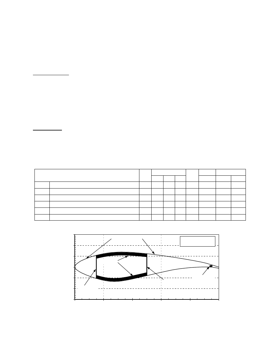
Design Process
The preliminary blade designs were developed
iteratively, beginning with an initial design of the blade
structure at selected spanwise stations and assuming the
structural architecture indicated in Figure 2. Each
station was evaluated to determine the governing
flapwise strength requirement (static or fatigue) and the
blade spar was sized using the ANSYS / NuMAD codes
so that the flapwise strength criteria were met. Once all
blade sections were sized for flapwise strength, the
resulting blade was evaluated for allowable tip
deflections. If the tip deflection criterion was met, then
the mass distribution was calculated and compared with
the baseline blade design. These data were used to
adjust the baseline edgewise bending fatigue spectra as
appropriate for the new blade design, and to evaluate
the edgewise bending strength of the blade sections.
Once the design of the blade sections was converged,
an ANSYS model was developed in which the sections
are connected in a three-dimensional blade.
The initial 3.0 MW blade design was an all-fiberglass
baseline configuration. Next, selected stations were
replaced with carbon / fiberglass hybrid spar caps and
the effect on blade weight and tip deflections
quantified. Finally, an example design was developed
assuming a fiberglass-to-carbon transition in the spar
cap at mid-span (50% R).
Table 1 Static Properties for Candidate Spar Cap Materials
Moduli (GPa)
Density
εεεε
design
(%)
Material # and Description
v
f
E
x
E
y
G
xy
νννν
xy
(kg/m
3
) Tens. Comp.
1
Woven glass uni + stitched glass triax, 70% 0
° 0.4 25.0 9.2 5.0 0.35 1750 1.01 0.45
2
Woven glass uni + stitched glass triax, 70% 0
° 0.5 29.0 10.2 6.0 0.31 1880 1.01 0.39
3
Prepreg glass uni + triax, 70% 0
°
0.5 29.0 10.2 6.0 0.31 1880 1.01 0.63
4
Stitched hybrid carbon / fiberglass triax, 70% 0
° 0.5 74.3 10.0 4.8 0.35 1621 0.50 0.34
5
Prepreg hybrid carbon / fiberglass triax, 70% 0
° 0.5 74.3 10.0 4.8 0.35 1621 0.55 0.37
6
“P4A” oriented discontinuous carbon preform
0.55 94.3 20.0 6.1 0.55
1540
0.50
0.41
-0.3
-0.2
-0.1
0.0
0.1
0.2
0.3
0.0
0.2
0.4
0.6
0.8
1.0
x/c
y/c
spar caps
aft shear web
forward
shear web
balsa-core skins
NREL S818 airfoil
scaled to 27% t/c
trailing-edge
spline
Figure 2 Architecture of baseline structural model
6
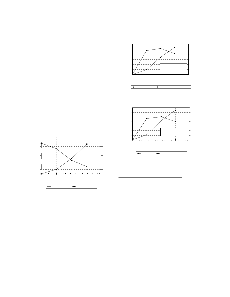
Spanwise Extent of Carbon Spar
A parametric assessment was performed to evaluate the
sensitivity of design parameters to the spanwise extent
of the carbon spar. Figures 3 through 5 illustrate the
results. The x-axis of each plot indicates the extent of
the “spar modification” modeled. Zero percent
modification represents the baseline blade with an all-
fiberglass spar cap. The spar modifications were
assumed to occur from the blade tip inward, so a 25%
spar modification implies that the outer quarter of the
blade spar is carbon / fiberglass hybrid, 50%
modification implies the outer half of the blade is
carbon hybrid, and so on.
Figure 3 shows the mass of carbon fiber used and the
value of the gravity-induced root bending moment, both
as functions of the carbon spar extent. Note that the
gravity-induced component of root bending is primarily
oriented in the edgewise direction of the blade
structure. As would be expected, the carbon fiber mass
used increases, and the gravity-induced bending loads
decrease as the carbon spar is extended inward along
the blade span.
800
900
1000
1100
1200
1300
1400
1500
1600
0%
25%
50%
75%
100%
Extent of Spar Modification (%R)
G
ravity R
oot-B
ending (kN
-m)
0
100
200
300
400
500
600
700
800
Mass of C
ar
bon Fiber
(kg)
Root Edge Moment
Carbon Fiber Mass
Figure 3 Gravity moments and carbon usage
Figure 4 shows the percentage change in gravity-
induced root bending moment (
∆ root moment), and
also the “normalized”
∆ root moment, where the
normalization represents the percentage change per 100
kg of carbon fiber used. The figure shows that the
greatest reduction in gravity-induced bending loads is
realized for a carbon spar extending from the tip to mid-
span. If the spar were carried further inboard, the
reductions in total blade mass would be large, but
because the distance to the root section is also
decreasing the mass reductions have a diminishing
effect on the gravity-induced moments.
Figure 5 shows a similar trend for changes in tip
deflection as a function of carbon spar extent. Again,
the greatest reductions in deflection are shown for a
carbon spar cap that spans the outer half of the blade.
-60%
-50%
-40%
-30%
-20%
-10%
0%
0%
25%
50%
75%
100%
Extent of Spar Modification (%R)
∆∆∆∆
R
oot
M
o
m
e
nt
-12%
-10%
-8%
-6%
-4%
-2%
0%
No
rmal
iz
ed
∆∆∆∆
R
oot
M
o
m
e
nt
Root Edge Moment
Normalized Root Edge Moment
"Normalized" delta is
percentage change in root
moment per 100 kg of carbon
fib
d i h b id bl d
Figure 4 Effect of carbon spar spanwise extent
on root bending moments
-14%
-12%
-10%
-8%
-6%
-4%
-2%
0%
0%
25%
50%
75%
100%
Extent of Spar Modification (%R)
∆∆∆∆
Tip D
eflection
-3.5%
-3.0%
-2.5%
-2.0%
-1.5%
-1.0%
-0.5%
0.0%
N
o
rm
alized
∆∆∆∆
Tip D
eflection
Tip Deflection
Normalized Tip Deflection
"Normalized" delta is
percentage change in tip
deflection per 100 kg of carbon
fib
d i h b id bl d
Figure 5 Effect of carbon spar spanwise extent
on blade tip deflections
Blade Design with Mid-Span Transition
In this section, a 3.0 MW blade design is developed
assuming a mid-span transition from a fiberglass to a
carbon hybrid spar cap. In the following section, the
technical challenges associated with such a transition
are presented and discussed.
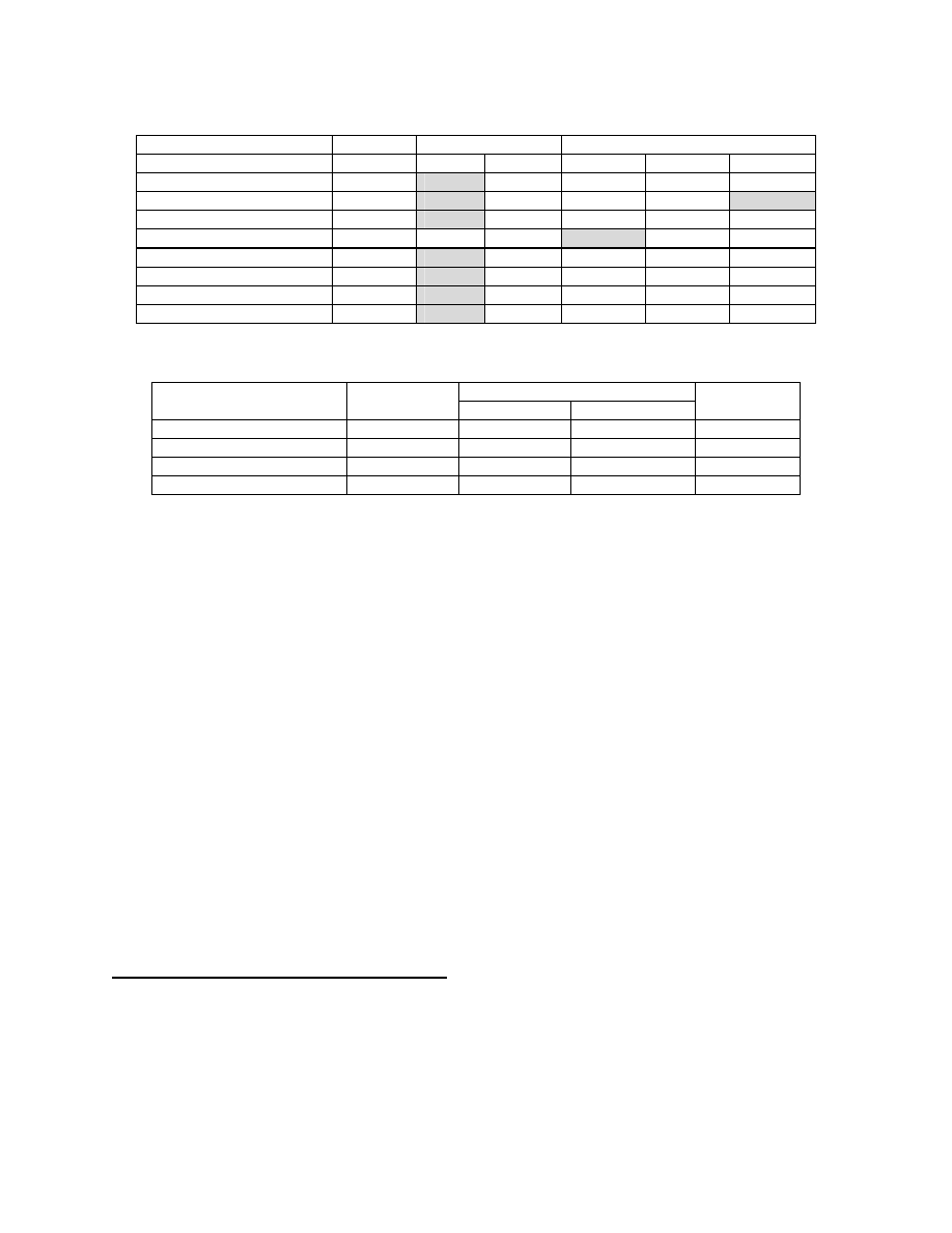
Table 2 lists the design margins for static and fatigue
strength at each spanwise section for both the fiberglass
and fiberglass / carbon hybrid blade designs. Shaded
entries indicate that a margin is at or near a governing
value. Margins for “compressive”, “tensile”, and
“reversed” strength correlate, respectively, to the upper,
lower, and trailing edge regions of the blade sections.
Static compression strength governs the inboard region
of the all-fiberglass blade. In addition, the 25% span
section also has a negative margin on edgewise fatigue
strength. At mid-span the design is critical in static
strength, but is also near-critical in compressive fatigue.
At the 75% span station, the fiberglass section is
governed by compressive fatigue strength. The all-
7
Table 2 Design Strength Margins for 3.0 MW Fiberglass / Carbon Hybrid Blade
Blade
Station
Static Margins (%)
Fatigue Margins (% Strength)
(%
R)
Comp.
Tens.
Comp.
Tens.
Reversed
Fiberglass Root
0.4
411 13.0 25.6 35.1
“ 25%
R
0.2
504 16.2 25.7 -5.3
“ 50%
R
0.3
332
3.5
11.7 34.7
“ 75%
R
10.5
289
0.1
10.6 262.3
Fiberglass / Carbon Hybrid
Root
0.4
411 13.0 25.6 50.4
“ 25%
R
0.2
504 16.2 25.7 7.3
“ 50%
R
0.6
161 43.5 139.8 50.4
“ 75%
R
-0.2
105 24.7 106.3
264.0
Table 3 Spar Cap Geometry for 3.0 MW Fiberglass / Carbon Hybrid Blade
Spar Cap Dimensions
Blade Section
Spanwise
Location (m)
Width (mm)
Thickness (mm)
Approximate
# of Plies
25% R, Fiberglass
12.4
1188
39.7
40
50% R, Fiberglass
24.8
912
40.8
41
50% R, Carbon Hybrid
24.8
912
18.3
18
75% R, Carbon Hybrid
37.2
633
70
7
fiberglass blade design also has a negative 5.5% margin
on allowable tip deflection (not shown in Table 2).
Although the negative margins on edgewise bending
and tip deflection could be remedied by selective use of
additional fiberglass materials, the substitution of a
carbon hybrid spar in the outer blade can also be used
to increase blade stiffness and decrease gravity-induced
bending loads.
The lower half of Table 2 shows the strength margins
for the 3.0 MW blade with an assumed fiberglass-to-
carbon transition at mid span. The root and 25% span
sections are structurally unchanged from the all-
fiberglass design as reflected by the flapwise margins
(compression and tension). However, due to the
reduced mass in the outboard part of the blade the
edgewise bending margins are improved over the entire
blade span and the margin at the 25% station is
increased from -5.3% to +7.3%. The margin on tip
deflection (not shown in the table) is also increased
from -5.5% to +2.5%. At 75% span, the governing
criterion has shifted from compressive fatigue to
compressive static strength.
Design / Manufacturing Issues for Spar Transition
As shown in the previous section, carbon fiber spars
appear be of greatest advantage for reducing gravity-
induced bending loads and tip deflections when located
in the outer blade span. However, there are significant
challenges to designing a fiberglass-to-carbon spar
transition that is structurally efficient and cost-effective
to manufacture.
One issue in a spar transition is the mismatch between
the carbon and fiberglass ply stiffness and strain-to-
failure. The most simple ply transition coupon would
be one with a single butt-joint between the dissimilar
plies. However, this is not likely to be a favorable
option from either a manufacturing or structural
performance standpoint, and so that arrangement is not
depicted herein. In any approach, maintaining
straightness in the carbon plies will be desirable for
preserving static compressive strength.
For reference, Figure 6 depicts a candidate spar cap
design with a fiberglass-to-carbon transition. The
thickness scale of these figures correctly reflects the
assumption that carbon layers are 1.0 mm thick whereas
the fiberglass layers are 1.25 mm thick. The horizontal
scale has been compressed to show the complete
transition. The transition dimensions were developed
assuming materials #2 (fiberglass) and #4 (carbon
hybrid) as described by Table 1. As a result of the
stiffness and compressive design strain, a 2.5-to-1.0
ratio of fiberglass-to-carbon laminate thickness is
required in regions where both materials are present.
Because the fiberglass materials have larger design
strains than the carbon, one of the fiberglass layers is
shown as being dropped following the transition region.
The ratios shown are only valid for specific
combinations of material and design strains, and could
be higher or lower for alternate materials.

8
6.25 mm
Additional
fiberglass
at end of
transition
7.5 mm
Additional
fiberglass at
max. build-up
3.0 mm
Carbon
layers
Assumes 3 continuous glass plies:
1) At outer spar cap surface.
2) Capping all carbon ply drops.
3) Capping all fiberglass ply drops.
Figure 6 Example candidate fiberglass-to-carbon spar transition
As a result of some structural inefficiency and the
manufacturing complexity of a mid-span fiberglass-to-
carbon spar transition, the preferable option may be to
extend the load-bearing carbon inboard to the blade
root. However, some testing is planned under the Part 2
BSDS to quantify the structural performance aspects of
such transitions.
TECHNICAL ISSUES AND RECOMMENDED
TESTING FOR PART 2 BSDS
The following sections discuss some of the specific
technical issues that were identified in the course of this
project, and corresponding recommendations for testing
under the Part 2 BSDS. The primary context for the
technical issues and testing is to establish the
performance of commercial (i.e. low-cost, large-tow)
carbon fiber in application to large wind turbine blades.
Material Types
Numerous material types have been identified,
reviewed and evaluated for application to wind turbine
blades during the course of this project, many of which
are currently in coupon testing as part of the DOE/MSU
database program. Items that have been assigned high
priority for the Part 2 BSDS include; large and
moderate tow size carbon fiber, prepreg and VARTM
infusion, and hybrid multi-layer multi-axial warp knit
(MMWK) fabric. In addition to a hybrid MMWK
fabric, dry carbon unidirectional fabric with
thermoplastic bead adhesion is a material form of high
interest.
It is expected that for a given fiber, laminate
manufactured with prepreg resin will have the best
static and fatigue strength. As a result of induced
waviness and other details, dry fabrics that are then
infused by VARTM are expected to have lower strength
performance. However, prepreg materials have
historically been more expensive and require higher
cure temperatures than liquid epoxy resin systems.
Currently, the majority of turbine blade manufacturers
use a “wet” process, either VARTM or a open mold
layup and impregnation. Dry layup of preforms and
subsequent infusion therefore remains as a process of
high interest for the wind industry.
To address this issue, the proposed Part 2 BSDS testing
will seek to answer several questions: What is the best
strength performance that can be obtained by
combining commercial carbon fibers in a low-cost
fabric / preform process with VARTM infusion? How
do the strength and estimated production costs compare
with prepreg versions of corresponding fibers? Is the
performance/cost ratio better for large or moderate tow
fibers? What appear to be the most cost-effective
combinations?
Thick Laminate
Thick laminate tests are expected to be of value to
evaluate several technical issues. The first is simply
thickness scaling of basic carbon / hybrid spar cap
laminate. In laminate with ideal fiber alignment, some
increase in compressive strength may be expected as
the thickness increases. However, the thicker laminate
will also include a greater distribution of naturally-
occurring material defects than the smaller coupons,
and also a greater opportunity for fabrication-related
irregularities. Given the relatively large strand size of
commercial carbon fibers and the heavy-weight fabrics
in use for large blades, some investigation of basic
thickness effects is planned.
Thick laminates can also be used to investigate details
that are not amenable to testing in thin coupons.
Examples in the current test matrix are multiple ply
drops, multiple ply transitions, and as-manufactured
laminate properties (effects of defects).

9
Ply Drops and Transitions
It is expected that ply drops in load-bearing carbon
spars will cause a greater decrease in fatigue strength
than in an equivalent fiberglass structure. This is due to
the fact that the carbon fibers are more highly loaded
than the fiberglass and as a consequence will shear a
higher load per unit area into the resin-rich region at the
ply termination. An additional effect may be due to any
waviness or jogs that are introduced in the remaining
carbon plies as a result of the ply drop. Ply thickness is
another important parameter for ply drops. The
technical issue at hand is the trade-off between the
increase in processing / handling efficiency of blade
construction and the decrease in fatigue performance at
ply drops which would be expected for the thicker
carbon plies.
In general, carbon-to-fiberglass ply transitions have all
of the technical considerations of carbon ply drops (i.e.
load transfer though resin-rich areas, sensitivity to
carbon layer straightness and ply thickness). However,
as discussed above ply transitions also add the
complication of mismatch between the carbon and
fiberglass ply stiffness and strain-to-failure.
Margins / Safety Factors
A starting point in determining margins and safety
factors is to develop a sufficient number of data points
so that statistically-based characteristic (i.e. 95%
exceedance with 95% confidence) properties can be
derived. Another aspect is the difference between
material properties as generated in coupon tests and the
performance of similar material in an as-built blade.
This encompasses a wide range of effects, some of
which are inherent (natural variations of material
properties, unavoidable variations in fiber and fabric
alignment, volume and thickness effects, inherent
process-related effects) and some of which can vary
depending on the execution of the manufacturing
approach (avoidable misalignment of fabric,
irregularities due to varying quality control of
fabrication and process).
The tests currently planned under the Part 2 BSDS to
address this issue assume thick laminate that is
constructed with designed and controlled irregularities
in the fiber alignment and/or void content. Such testing
is more correctly characterized as evaluating the
“effects of defects” and only addresses a subset of the
effects that combine in “as-manufactured properties”
Biased Fabrics
Although not formally included in the trade-off studies
of the Part 1 BSDS, biased carbon-fiberglass hybrid
materials are of interest for testing under the Part 2
study. The motivation for including these materials is
that modeling under the WindPACT Rotor Study
predicts substantial COE reductions for twist-coupled
blades, and biased carbon-fiberglass laminate has been
identified as a promising approach to cost-effective
manufacture of such blades. There are also several
other ongoing DOE-funded research efforts in the area
of twist-coupled blades, but at this time property
characterization data are lacking for the material
combinations of interest.
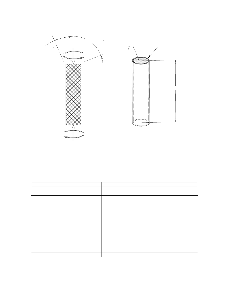
Figure 7 shows a schematic representation of a
candidate test that incorporates biased carbon /
fiberglass laminate in a tubular specimen with
combined axial and torsional loading. The dimensions
and fiber orientation angles shown the figure are
nominal, but were used in specifying the required test
equipment and estimating costs for part fabrication and
testing. It is assumed that the parts can be fabricated by
wrapping a biased carbon / fiberglass fabric around a
foam core, with subsequent infusion. The article would
then have an extension-twist bias. When loaded
axially, the laminate would respond much as biased
material would on either the upper or lower surface of a
turbine blade (assuming mirror symmetry of upper and
lower surface laminate to achieve bend-twist coupling).
With the proposed design, the axial and torsional
degrees of freedom can be loaded independently, or
either can be left free. From the test measurements, the
laminate properties E
x
, G
xy
, and
η
x,xy
(measure of the
amount of shear strain generated in the x-y plane per
unit strain in the x-direction) can be inferred.
Following an evaluation of the material stiffness
properties, the article can be progressively loaded to
failure. The measured stiffness and strength properties
can then be compared with values predicted by
micromechanics.
Summary of Recommended Tests
Table 4 provides a summary of the technical issues
identified, and types of testing recommended for
resolving each issue under the Part 2 BSDS. For the
majority of the tests listed, both static and fatigue
testing would be of practical interest.
10
Carbon at 20
Fiberglass at -70
P
P
T
T
150 mm
Foam core
38 mm
Biased skin
6 plies nominal
Figure 7 Schematic of candidate test for biased tube in combined axial / torsional loading
Table 4 Summary of Technical Issues and Recommended Tests for the Part 2 BSDS
Technical Issue
Type of Testing Recommended / Planned
Basic performance of candidate materials
•
Thin coupon
•
Thick coupon
Ply drops
•
Thin coupon (single ply drop)
•
Thick coupon (multiple ply drops)
•
Internal and external drops
•
Variations on ply thickness
Carbon / fiberglass ply transitions
•
Thin coupon (single ply drop)
•
Thick coupon (multiple ply drops)
•
Variations on ply thickness
Performance of complete spar design, with
ply drops and/or transitions
•
4-point beam bending
Margins and safety factors
•
Thin coupons (development of statistical data for
selected material / process combinations)
•
Thick coupons with pre-designed irregularities (effects
of defects)
Biased fabrics
•
Specialty cylinder in combined axial / torsional loading

11
CONCLUSIONS
In the Part 1 BSDS, constraints were identified to cost-
effective scaling-up of the current commercial blade
designs and manufacturing methods, and candidate
innovations in composite materials, manufacturing
processes and structural configurations were assessed.
Preliminary structural designs were developed for
hybrid carbon fiber / fiberglass blades at system ratings
of 3.0 and 5.0 megawatts. Structural performance was
evaluated for various arrangements of the carbon blade
spar, and critical performance aspects of the carbon
material and blade structure are discussed. To address
the technical uncertainties identified, recommendations
were made for new testing of composite coupons and
blade sub-structure. These test efforts are currently
ongoing under the Part 2 BSDS.
ACKNOWLEDGEMENTS
This work was completed for Sandia National
Laboratories as part of the U.S. Department of Energy’s
WindPACT program, under Sandia Purchase Order No.
13473. The author wishes to acknowledge the
contributions of Sandia Technical Monitor Tom
Ashwill, Paul Veers, and other Sandia personnel to this
project. The NuMAD interface to ANSYS, developed
by Daniel Larid of Sandia, was used extensively to
facilitate the blade design and analyses performed.
This project has also benefited from extensive
collaboration with manufacturers of composite
materials, wind turbine blades, and other composite
structures. Mike Zuteck consulted on all phases of this
project, and John Mandell of MSU made significant
technical contributions in material selection,
development of laminate properties, and design and
planning for composites testing.
REFERENCES
1. BTM
Consult ApS.,
A Towering Performance –
Latest BTM Report on the Wind Industry,
Renewable Energy World, July-August 2001, p.p.
69-87, James & James (Science Publishers Ltd.),
London UK.
2. Dutton, A.G., et. al. (March 1-5, 1999). Design
Concepts for Sectional Wind Turbine Blades.
Proceedings of the 1999 European Wind Energy
Conference, Nice, France. p.p. 285-288.
3. Joosse, P.A., et al. (January 10-13, 2000).
Economic Use of Carbon Fibres in Large Wind
Turbine Blades? Proceedings of AIAA/ASME
Wind Energy Symposium. Reno, NV.
4. Joosse, P.A., et al. (July 2-6, 2001). Toward Cost
Effective Large Turbine Components with Carbon
Fibers. Presented at the 2001 European Wind
Energy Conference and Exhibition, Copenhagen.
5. Joosse, P.A., et al. (July 2-6, 2001). Fatigue
Properties of Low-Cost Carbon Fiber Material.
Presented at the 2001 European Wind Energy
Conference and Exhibition, Copenhagen.
6. Joosse, P.A., et al. (January 14-17, 2002). Toward
Cost Effective Large Turbine Components with
Carbon Fibers. Proceedings of AIAA/ASME
Wind Energy Symposium. Reno, NV.
7. Griffin, D.A. (March, 2001). WindPACT Turbine
Design Scaling Studies Technical Area 1 –
Composite Blades for 80- to 120-Meter Rotor.
NREL/SR-500-29492. Golden, CO: National
Renewable Energy Laboratory.
8. Smith, K. (March, 2001). WindPACT Turbine
Design Scaling Studies Technical Area 2 –
Turbine, Rotor and Blade Logistics. NREL/SR-
500-29439. Golden, CO: National Renewable
Energy Laboratory.
9. Vandenbosche, J. (March, 2001). WindPACT
Turbine Design Scaling Studies Technical Area 3 –
Self-Erecting Tower Structures. NREL/SR-500-
29493. Golden, CO: National Renewable Energy
Laboratory.
10. Malcolm, D., Hansen C. (June, 2001) Results from
the WindPACT Rotor Design Study. Proceedings
Windpower 2001, American Wind Energy
Association, Washington DC.
11. Malcolm, D.J. and Hansen, A.C. (June 2002).
Lessons from the WindPACT Rotor Design Study.
Poster presentation at WindPower2002. American
Wind Energy Association, Portland OR.
12. Griffin, D.A. (July, 2002). Blade System Design
Studies Volume I: Composite Technologies for
Large Wind Turbine Blades. SAND2002-1879.
Albuquerque, NM: Sandia National Laboratories.
13. Laird, D.L. (January 11-14, 2001). 2001: A
Numerical Manufacturing and Design Tool
Odyssey. Proceedings of AIAA/ASME Wind
Energy Symposium. Reno, NV.
14. Service, D. (October 16-18, 2001). PAN Carbon
Fibre Precursor. Proceedings of Intertech’s
Carbon Fiber 2001, Bordeaux, France.
15. International Electrotechnical Commission. (1999).
IEC 61400-1: Wind turbine generator systems –
Part 1: Safety Requirements, 2
nd
Edition.
International Standard 1400-1.
16. Germanischer Lloyd (1999) Rules and Regulations
IV – Non-Marine Technology, Part 1 – Wind
Energy, Regulation for the Certification of Wind
Energy Conversion Systems.
17.
Mandell, J.F., Samborsky, D.D. (1997).
“DOE/MSU Composite Material Fatigue
Database: Test Methods, Materials and Analysis.”
SAND97-3002. Sandia National Laboratories.
Albuquerque, NM.
Document Outline
- ALTERNATIVE COMPOSITE MATERIALS FOR MEGAWATT-SCALE WIND TURBINE BLADES:
- DESIGN CONSIDERATIONS AND RECOMMENDED TESTING
- ABSTRACT
- NOMENCLATURE
- BACKGROUND
- APPROACH
- GENERAL ISSUES FOR MW-SCALE BLADES
- PRELIMINARY DESIGN OF 3.0 MW BLADE
- f
- A
- TECHNICAL ISSUES AND RECOMMENDED TESTING FOR PART 2 BSDS
- C
- CONCLUSIONS
- ACKNOWLEDGEMENTS
- REFERENCES
Wyszukiwarka
Podobne podstrony:
Innovative Solutions In Power Electronics For Variable Speed Wind Turbines
Advanced Methods for Development of Wind turbine models for control designe
Separation Control Of High Angle Of Attack Airfoil For Vertical Axis Wind Turbines
Design Requirements For Medium Sized Wind Turbines For Remote And Hybrid Power Systems
The Material Selection for Typical Wind Turbine Blades 2006
Blade sections for wind turbine and tidal current turbine applications—current status and future cha
Modeling Of The Wind Turbine With A Doubly Fed Induction Generator For Grid Integration Studies
Development of wind turbine control algorithms for industrial use
Compliant Blades For Wind Turbines
An Igbt Inverter For Interfacing Small Scale Wind Generators To Single Phase Distributed Power Gener
Boost Converter Design For 20Kw Wind Turbine Generator
Development Of A Single Phase Inverter For Small Wind Turbine
A Low Speed, High Torque, Direct Drive Permanent Magnet Generator For Wind Turbines
0 Simulation of fatigue failure in a full composite wind turbine blade Shokrieh Rafiee 2006
więcej podobnych podstron