European Wind Energy Conference & Exhibition. February-March 2006, Athens.
1
1 Introduction
Wind energy has developed considerably over the
last decade. Its implementation in the electrical
system is already widespread in countries such as
Germany, Denmark or Spain and an increasingly
greater impact is predicted. The implementation of
these technologies brings a set of advantages
foremost amongst which is a reduction in CO2
emissions and access to clean energy sources in those
countries without fossil energy resources.
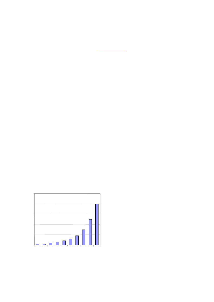
Established trends point to an increase in unitary
power, with ever greater machines being
manufactured such as those shown in Fig. 1. This
trend has led to the development of offshore wind
farms, where large multimegawatt turbines may be
installed.
Nevertheless, important problems and challenges
remain to be tackled if we are not to endanger the
stability of the electrical system.
Fig. 1. Evolution of unitary power.
In this context, grid codes which define the new
requirements for grid connection of wind farms have
either been developed or are in process in those
countries with a higher installed power. There are
basically three main aspects covered in the grid codes
(1): voltage and reactive power control, frequency
control, and fault ride-through capabilities.
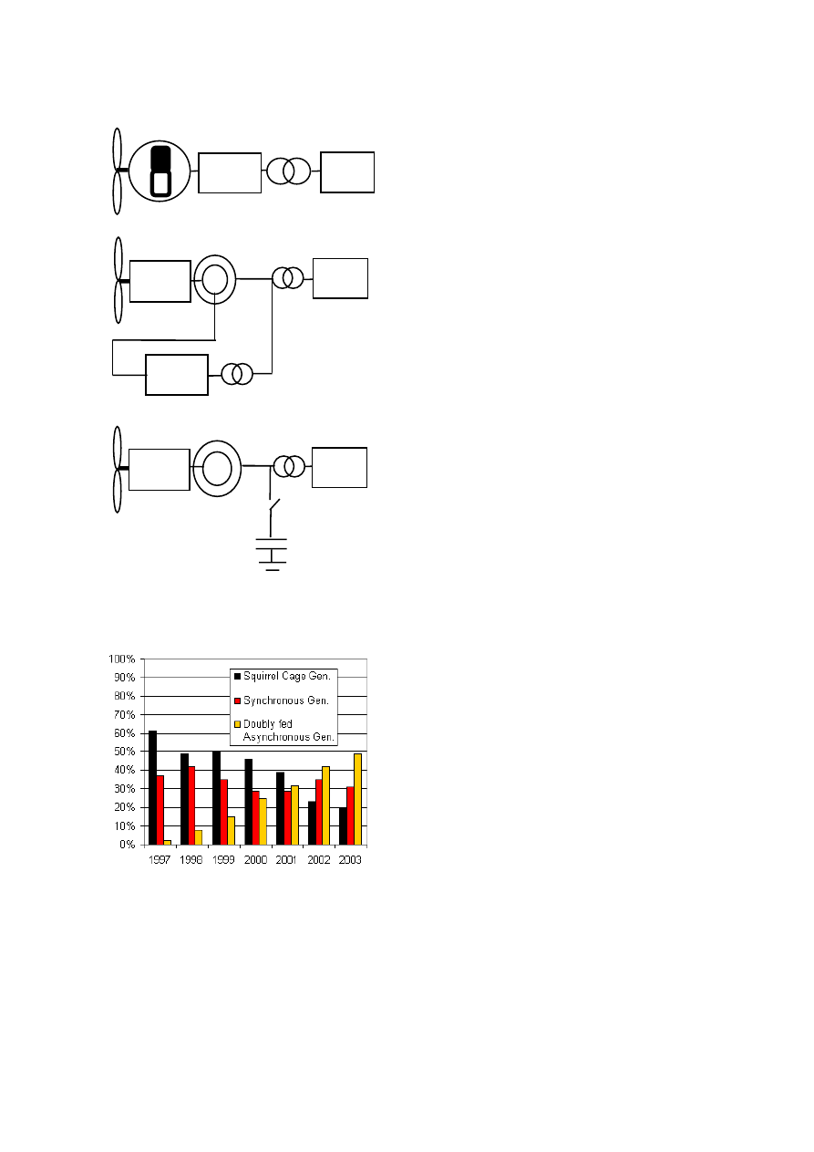
There are three main types of wind turbine at the
present time (2). On the one hand we have fixed-
speed turbines based on asynchronous generators
with a squirrel-cage rotor, and on the other the
variable speed turbines which use doubly-fed
asynchronous generators or synchronous generators
in a full converter configuration. (Fig. 2).
Fig. 3 shows the evolution in the use of these
generators over the last few years. It can be observed
that variable speed configurations are gaining ground
over the asynchronous squirrel-cage generator.
The aim of this paper is to review the power
electronics solutions applicable to variable speed
turbines, with a view to meeting the challenges
facing wind generation (higher powered turbines and
quality requirements and ever more demanding grid
connections).
The article begins with a review of the commutation
devices which are currently available on the market.
Three topologies are subsequently presented whose
features make them attractive for use in wind
applications. Finally, an analysis of a multilevel
converter is carried out with the aim of validating the
most advantageous features within the field of wind
generation.
INNOVATIVE SOLUTIONS IN POWER ELECTRONICS FOR VARIABLE SPEED WIND TURBINES
J.L. VILLATE, E. ROBLES, P. IBÁÑEZ, I. GABIOLA, S. CEBALLOS
ROBOTIKER , Parque Tecnológico Edif. 202 48170 Zamudio (Bizkaia), Spain.
joseluis@robotiker.es
Tél : + 34 94 600 22 66, Fax : + 34 94 600 22 99
ABSTRACT: Wind energy has experienced a dramatic development over the last decade. Offshore wind farms with multi-
megawatt machines and variable speed solutions are gaining ground. The power converter is a key component in modern
wind turbines with higher power, higher efficiency and lower costs. In addition, the utilities demand increasingly exacting
power quality requirements, which can only be met if research on power converters is done. This paper presents a survey of
existing power electronics solutions for wind turbines, covering trends and new studies in this field.
Keywords: Power electronics, variable speed wind turbines, multilevel converters, matrix converters.
0
1000
2000
3000
4000
5000
1986198819901992 19941996 199820002002 2004
kW
European Wind Energy Conference & Exhibition. February-March 2006, Athens.
2
Fig. 2. Wind turbine configurations. (a) Synchronous
generator. (b) Doubly fed asynchronous generator.
(c) Squirrel Cage Generator.
Fig. 3. Evolution of wind generator technology.
2 Semiconductor devices
This section will make a brief analysis of the current
state of semiconductor power devices. These devices
represent the basic element in a converter
commutation process, since the efficiency of the
converter depends on the characteristics of these
devices.
They may be classified into three groups depending
on their degree of controllability.
1. Diodes. These are controlled by the
currents and voltages of the power circuit.
2. Thyristors (SCR). These devices are
activated through a control signal although
they are then deactivated through the
power circuit.
3. Controllable switches. Activated and
deactivated through a control signal.
Amongst the latter group the MOSFET, IGBTs and
IGCTs should be stressed.
MOSFET devices are used in lower power
applications with high commutation frequencies.
Their main disadvantage is a high resistance to
conduction, though fortunately there are new
technologies available on the market which have
resulted in the appearance of 'CoolMos', in which
conduction resistance has been reduced, thereby
improving behaviour.
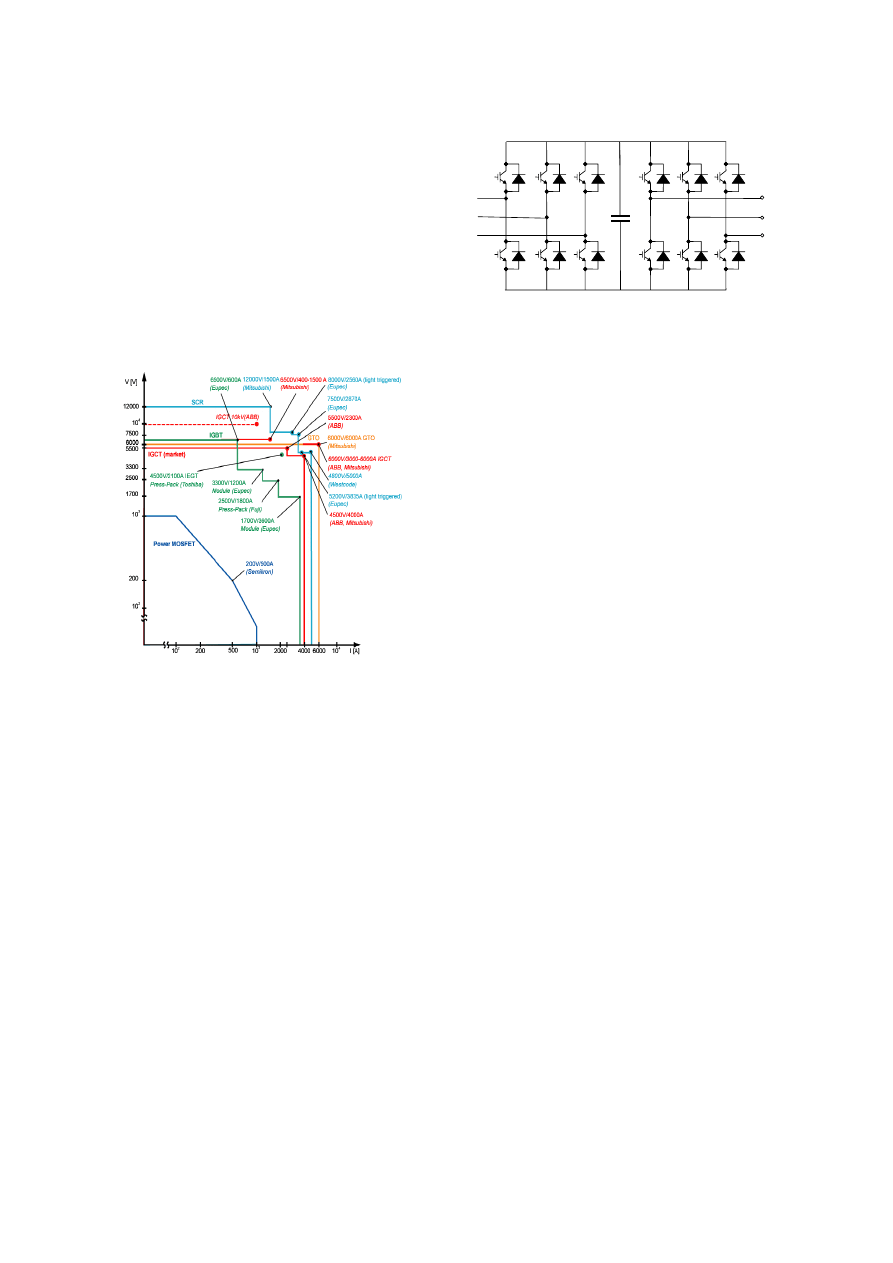
The most used semiconductor devices are currently
the IGBT's. There are IGBTs from 600V to 3300V,
capable of withstanding currents up to 3600A
(depending on the voltage, see Fig. 4 [2]). The IGBT
has been improving its features over a period of time.
Nevertheless, due to its particular structure, an
ongoing improvement to an equal degree across all
its features is not possible, which has led to
specialised devices being developed to perfect
particular features. We may thus find ultrafast
IGBTs possessing excellent speed features with
acceptable losses, together with generic IGBTs and
HVIGBTs (high voltage IGBTs) which allow for
high working voltages permitting their use in
medium voltage application.
A trend towards the use of IGBTs with NPT (non
punch through) structures can be seen in the market
in order to facilitate parallel connection.
Furthermore, we must not forget that this technology
is both more robust in the presence of short circuits
as well as cheaper to manufacture.
Finally, the appearance of IGCTs represents a
substantial improvement on GTOs since they
combine the high voltages and low losses of the latter
with the high frequencies and small commutation
losses of the IGBTs.
Developments within the last two components
(IGBTs and IGCTs) together with a reduction in their
cost have both been fundamental factors giving rise
to the implementation of PWM VSC (voltage source
converter) over the rectifiers and cicloconverters
previously used.
(c)
AC-AC
GRID
GEAR
AC-AC
GRID
GEAR
GRID
(a)
(b)
European Wind Energy Conference & Exhibition. February-March 2006, Athens.
3
Fig. 4 [3] shows the power range of some
semiconductor devices currently available on the
market.
All these devices are based on silicon, though the
material best placed for using in the near future will
be silicon carbide, due to its physical properties.
Amongst other advantages from using this material
we may stress its greater energy efficiency, improved
reliability and reduced maintenance costs, together
with greater operation frequencies, integration
density and high operation temperatures.
Fig. 4. Semiconductor devices currently available on
the market.
3 Power Converters
In this section we will analyse the most attractive
power converters for use in wind applications. The
first to be analysed will be the two-level back to back
connection converter which is practically the only
one which is currently used in this type of
application. We will then go on to propose three
topologies (multilevel, matrix and AC link
converters) whose features may prove useful in near
future applications.
PWM back to back converter
Fig. 5 shows a diagram of this converter. As shown
it is made up of two 2-level converters linked by
means of a DC bus. This bus allows us to uncouple
the two converters, whereby one does not influence
the other so that they may be controlled separately.
However, the size and weight of the DC link can be
high, making a reduction desirable as far as possible.
This objective brings us on to some of the following
topologies, which are not exempt from problems
themselves as shall be seen.
Fig. 5. Back to Back PWM two level converter.
Multilevel Converters
Multilevel converters are based on connecting
together a set of various semiconductor devices,
thereby allowing greater working voltages to be
reached, which in turn increases the power they are
able to handle. This feature can be useful in current
wind applications, since the unitary power of each
wind turbine has increased exponentially over the
past few years as we have seen.
Its working principle is based on the generation of a
staircase waveform formed by more than two levels
of voltage. The waveforms thus generated present a
more sinusoidal nature than those generated by two-
level converters thereby allowing a greater quality in
generated energy.
The main advantages deriving from the use of this
type of topology are the following:
•
Possibility of reaching high output voltages
without submitting the semiconductors to
high voltages.
•
Better efficiency across the whole power
range, relatively more stressed when
working with low input powers [4].
•
Low harmonic content in the voltages and
currents generated, or in other words the
possibility of reducing the commutation
frequency of the semiconductor devices
and size of the grid connection inductances
while obtaining a similar quality as with a
two-level converter.
All these advantages make the multilevel converter a
good alternative in wind energy applications. It helps
to fulfil the objectives of improved quality in energy
generated, and allows greater working powers to be
reached whilst minimising losses. This in turn results
in a simpler design of the dissipating elements.
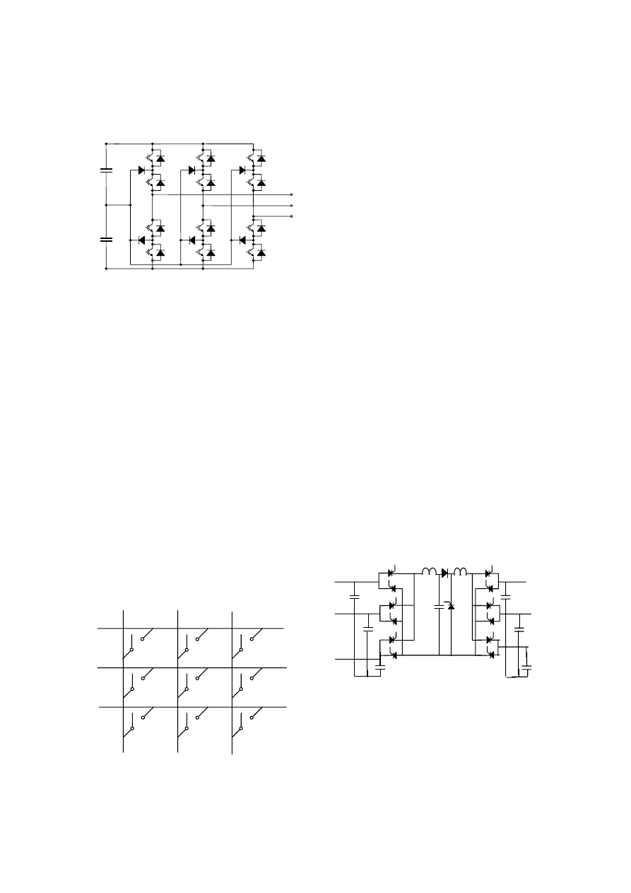
These days a large number of topologies of
multilevel converters are being proposed, with the
three main ones being “diode clamped topology",
"flying capacitor topology" and "cascaded connection
of H bridges" [5]. Of these the most frequently used
at the present time is the three level diode clamped
C
European Wind Energy Conference & Exhibition. February-March 2006, Athens.
4
converter since it requires a lesser number of
capacitive components and voltage sources than the
other two. This topology is shown in Fig. 6.
Fig 6. Three level diode clamped converter.
Matrix Converters
Fig. 7 shows the scheme of a three-phase matrix
converter. As may be observed, it is generally made
up of an array of n x m bidirectional switches.
Its working principle is based on connecting the
output phases to the input ones for as long as
necessary to be able to obtain the desired average
voltage from the output and current from the input.
The main characteristic of the matrix converter lies in
its being a solution based wholly on silicon, without
reactive elements to augment the weight, volume and
cost of the converter. Although it is necessary to
improve its working by introducing an input filter to
improve the currents generated and clamping circuit,
the size of these elements will always be smaller than
those used in other topologies.
Another important feature which should be stressed
is that this converter is totally bi-directional and also
very suitable to work in environments where the
power generated is continuously changing. This
makes it very attractive for use in wind systems.
Fig. 7. 3x3 Matrix converter.
Its main disadvantages include the fact that if
overmodulation is not produced, the maximum level
produced at output is 0.866 times that of the input.
As such, in order to obtain the same power as in a
back to back converter, it will be necessary to
oversize the semiconductor devices besides
increasing the conduction losses.
Another aspect which is necessary to improve in this
type of converter is its Ride-Through capability,
since due to the absence of the continuous bus there
are no energy storage elements.
In conclusion, we may say that despite the very
useful possibilities offered by this technology, it is
still not sufficiently mature to apply in real-life
situations, with several aspects such as the one above
still needing a solution. Despite of this, there are
some works that incorporate this technology in wind
turbines [6].
AC-link converter
Fig. 8 shows the scheme of this converter [7]. Its way
of working is completely different to the converters
commented on up to now. In this case it is based on
the transfer of load packets between input and output
(using the central capacitor), depending on the power
required for the application and the value of the
currents needed to generate at both input and output
at any given time.
Amongst its advantages we can stress a reduction in
the size of the central capacitor and filters in
comparison with the back to back converter, high
performance, use of slow commutation devices such
as SCRs and the low dv/dt it generates.
Another important feature is its low cost making it
generally attractive for installation in turbines located
in areas lacking in wind.
Fig. 8. AC-link converter.
4 Analysis of a multilevel converter
In the previous section we have described three of the
emerging topologies for use in wind applications. Of
these the most mature technology is that of multilevel
converters, since despite being barely used in this
field it is very tried and tested in other applications.
a
b
c
A
B
C
European Wind Energy Conference & Exhibition. February-March 2006, Athens.
5
Two of the main benefits presented by the topology
described above will be analysed in this section,
namely an increase in efficiency and quality
improvement in the currents generated.
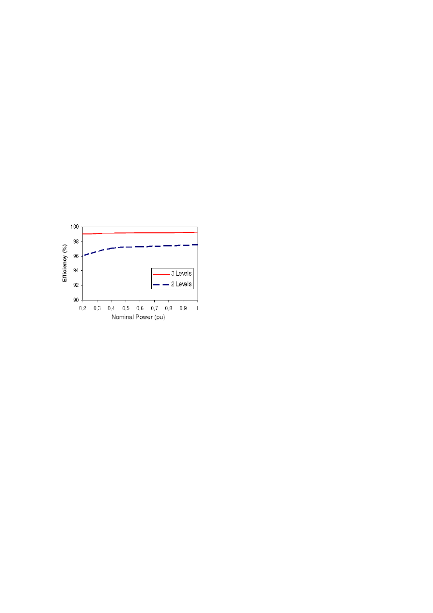
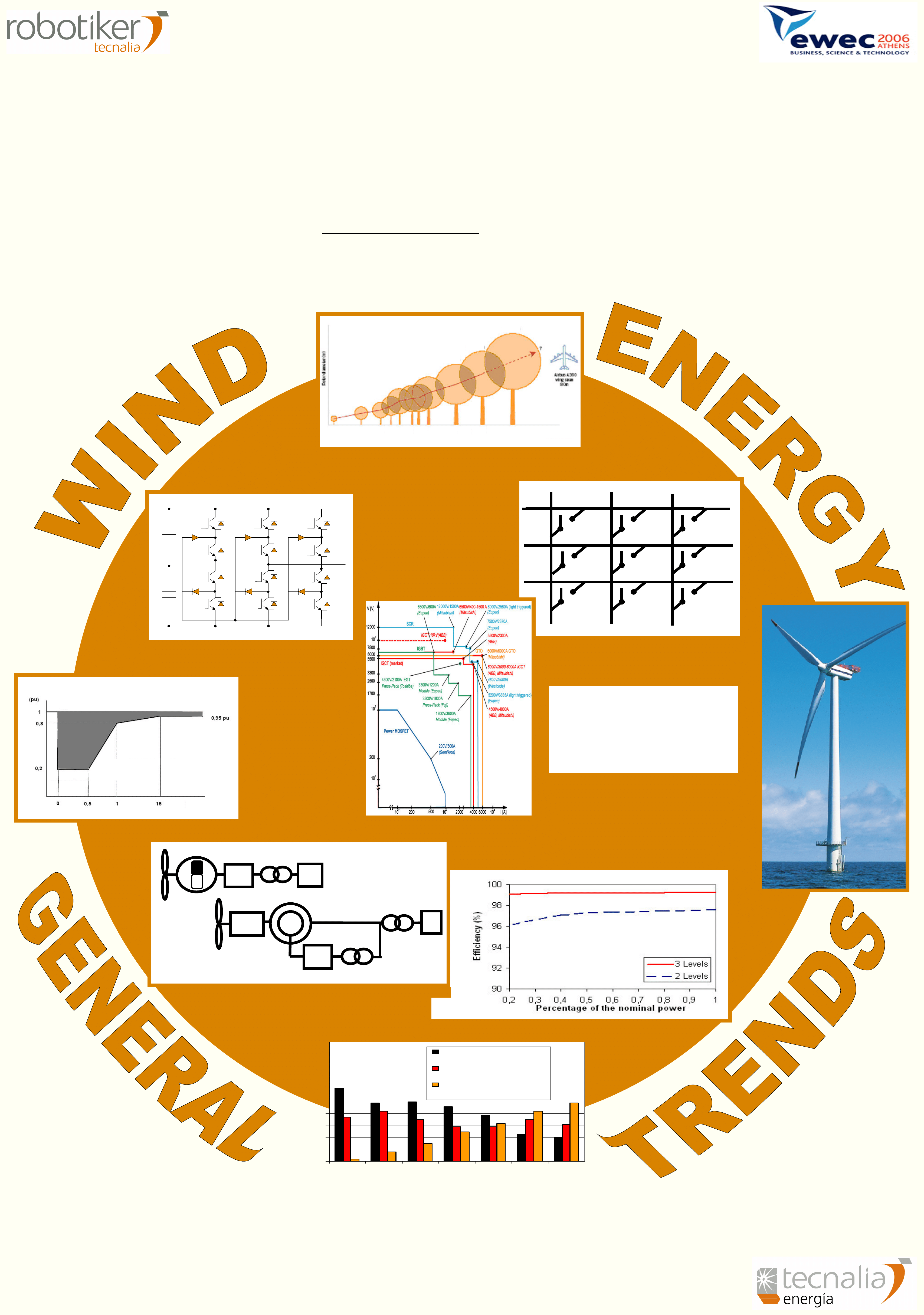
Fig. 9 [8] shows the results in performance obtained
by carrying out simulations of a two and three level
clamped converter by levels of 2MW commuting at
5KHz. It may be observed that the multilevel
converter presents a greater efficiency across the
whole working power range.
Experimental quality measurements of current
injected into the grid at different percentages of
nominal power have also been taken. This
measurements show that the three level diode
clamped converter allows to reduce the THD in a
20% compared with those generated by a two level
converter.
Fig. 9. Efficiency curves for two and three level
converters.
5 Conclusions
This paper has carried out an analysis of
semiconductor devices currently available on the
market. Three topologies of converters are proposed
which may start to be installed in variable speed wind
turbines in the foreseeable future, responding to the
ever more exacting requirements demanded of wind
generation.
Finally, the features of one of the topologies
proposed (the multilevel converter) is analysed, and
compared with those of a two-level converter,
practically the only topology in current use. The
results clearly show the advantages which would be
brought by the use of multilevel topologies.
6 Acknowledgements
This work has been developed with the support of the
Basque Government under the programme
SAIOTEK and the Education and Science Ministry
of Spain (project RECENER ENE/2004-07881-C03-
03/ALT).
7 References
[1] I. Martínez de Alegría, J. Andreu, J.L. Martín, P.
Ibáñez, J.L. Villate, H. Camblong, “Connection
requirements for wind farm: A survey on
technical requirements and regulation,”
Renewable and Sustainable Energy Review.
[2] L.H. Hansen, L. Helle, F. Blaabjerg, E. Ritchie,
S. Munk-Nielsen, H. Bindner, P. Sorensen and B.
Bak-Jensen, “Conceptual survey of Generators
and Power Electronics for Wind Turbines,” RISØ
National Laboratory, Roskilde, Denmark,
December 2001.
[3] S. Bernet, “Recent Developments of High Power
Converters for Industry and Traction
Applicatios,” IEEE Trans. on Power Electronics,
Vol. 15, nº6, pp. 1102-1117, November 2000.
[4] L.M. Tolbert, F.Z. Peng and T.G. Habetler
“Multilevel Inverters for Electric Vehicle
Applications,” WPET’98. pp. 79-84, Dearborn,
Michigan 22-23 October 1998.
[5] J. Rodríguez, J-S Lai and F.Z. Peng, “Multilevel
Inverters: A Survey of Topologies, Controls and
Aplications,” IEEE Trans. Indus. Electron., vol.
49, no. 4, pp. 724-738, August 2002.
[6] Patent. US 6856038, feb. 15 2005 Rebsdorf,
A.V, Helle, L, “Variable speed wind turbine
having a matrix converter”. (Industrial property:
Vestas).
[7]
http://www.princetonpower.com/tech/ACLink_Tech
_Operation.pdf (Last access February 2006)
[8] J.L. Villate, S. Ceballos, E. Robles, P. Ibáñez, I.
Gabiola, “Experimental validation of multilevel
Converters for Variable Speed Wind Turbines”
EPE 2005. Dresden, September 2005.
!!!!
""""
#
! $
#
! $
#
! $
#
! $
%
&
%
&
%
&
%
&
'
'
'
'(
) (
(
) (
(
) (
(
) (
*
+,
+ (- . /
0 1 ( +2 ,
,( 3
2 , 4
1 3 +
, 2 ,
/
55 / (
6 +, 5 (3 6 / 3&
73 - 6
3 2/ +
+, 4 (
1
,
&
+
( -
+ +- - ( & +,
/ 1 6 ( 2 +4 ( (
) . 2 31 + + + 3 , (+ 6 +, & ( +
6 / / - / ( 1 6 ( / - / ( 55 2 +2.
+,
6 ( 2
+
,
+ ,,
+ &
, 3 +, +2(
+- .
0 2 +- 1 6 ( 8 &
. ( 8 & ( 3 +
6/ 2/ 2 + + .
3
5 (
(2/ + 1 6 ( 2 +4 ( (
, +
/
1 1 ( 1 (
+
& (4 .
5 0
+- 1 6 (
2 ( + 2
&
+ 5 ( 6 +, & ( +
( +,
+, + 6
& ,
+ /
5
,
+, & ( +
(
4
4 +-
6 (, / - / ( 1 6 ( +, 4 (
1
, 1 ( . (
,
/ , 4
1 3 +
5 55 / ( 6 +, 5 (3
/
( +, +, / + 6 ( 8 & ( 3 +
5 - ( , 2 ,
3 )
1 6 ( 2 +4 ( (
) . 2 31 + + + 3 , (+ 6 +, & ( +
/
1 1 (
+ .
/
3 ()
&
+
+ 1 6 (
3 2 +,& 2 ( , 4 2
+, + 6 2 +2 1
5 ( 1 6 ( 2 +4 (
+ 2 (2&
+
1 ( 2&
( / 1
+
,4 + -
5 3&
4
2 +4 ( (
(
,
55 2 +2.
+, 1 6 ( 8 &
.
(
& , ,*
9
Greater efficiency across the whole power range.
9
6 ( / (3 + 2 ,
(
+
0%
10%
20%
30%
40%
50%
60%
70%
80%
90%
100%
1997
1998
1999
2000
2001
2002
2003
Squirrel Cage Gen.
Synchronous Gen.
Doubly fed
Asynchronous Gen.
GRID
POWER
ELECTRONICS
SOLUTIONS
(3 + +
(3 + +
(3 + +
(3 + +
Magnet
!
+ (
(
!
+ (
(
!
+ (
(
!
+ (
(
&
.
, +,& 2
+
&
.
, +,& 2
+
&
.
, +,& 2
+
&
.
, +,& 2
+
!
+ (
(
!
+ (
(
!
+ (
(
!
+ (
(
GEAR
AC-AC
AC-AC
GRID
GRID
a
b
c
A
B
C
Source: Recent Developments of High Power Converters for Industry and
Traction Apllications. Steffen Bernet
EVOLUTION IN SIZE AND CAPACITY OF WIND TURBINES (Source: Jos Beurskens - ECN)
85
87
89
91
93
95
97
99
01
03
05
?
0.05
0.3
0.5
1.3
1.6
2
4.5
5
8/10 MW
15 m
112 m
126 m
160 m
Voltage
Time (s)
3-LEVEL CONVERTER
3-PHASE MATRIX CONVERTER
EFFICIENCY OF A 2 MW 3-LEVEL CONVERTER
POWER SEMICONDUCTOR DEVICES
VARIABLE SPEED WIND TURBINES
VOLTAGE DIP
WIND GENERATOR TECHNOLOGY
VESTAS
Source: Spanish grid code
Wyszukiwarka
Podobne podstrony:
[2001] State of the Art of Variable Speed Wind turbines
20050253396 Variable Speed Wind Turbine Generator
Control Issues Of A Permanent Magnet Generator Variable Speed Wind Turbine
Grid Impact Of A 20 Kw Variable Speed Wind Turbine
[2001] State of the Art of Variable Speed Wind turbines
[2001] State of the Art of Variable Speed Wind turbines
20050253396 Variable Speed Wind Turbine Generator
A Cage Induction Generator Using Back To Back Pwm Converter For Variable Speed Grid Connected Wind E
Design Requirements For Medium Sized Wind Turbines For Remote And Hybrid Power Systems
Advanced Methods for Development of Wind turbine models for control designe
0 Alternative Composite Materials for Megawatt Scale Wind Turbines Griffin Ashwill 2003
Separation Control Of High Angle Of Attack Airfoil For Vertical Axis Wind Turbines
Conducted EMI in PWM Inverter for Household Electric Appliance
[US 2005] 6864611 Synchronous generator for service in wind power plants, as well as a wind power
(ebook electronics) Schematics Power Regulated Power Supply for CB & Ham Radio
więcej podobnych podstron