Separation Control of High Angle of Attack Airfoil
for Vertical Axis Wind Turbines
Keiko Fukudome
1
, Masashi Watanabe
2
, Akiyoshi Iida
2
& Akisato Mizuno
2
1
Graduate School of Engineering, Kogakuin University, Japan
2
Department of Mechanical Engineering Kogakuin University, Japan
Keywords: Wind Turbine, Flow control, Separation, Flow Visualization
Abstract
: The aim of this investigation is to develop the high performance vertical axis wind turbine (VAWT) with
turbulence promoters. An angle of attack of turbine blades in VAWT changes from a plus to a minus broadly.
Symmetric vortex generators are therefore required to develop the turbulence promoters for VAWT. A thin tripping
wire introduces at the upstream stagnation point as a symmetric turbulence promoter. In order to evaluate an effect
of the turbulence promoters, wind tunnel experiments and numerical simulations were carried out. As a result,
turbulence promoter delayed the flow separation at the high angle of attack. Lifting force is larger than that of
conventional airfoils by using the turbulence promoter. It reveals that the tripping wire on the leading edge is an
effective device to improve performance of the VAWT.
1. Introduction
From a viewpoint of environmental conservations of
energy resources, developments of renewable natural
energy are needed. Wind turbines attract attention
globally as important renewable energy systems.
Vertical Axis Wind Turbines (hereafter VAWT) are
one of the useful renewable energy systems. VAWT
have several advantages in comparison with the
conventional propeller typed, horizontal axis wind
turbines (hereafter HAWT). For example, the
conventional wind turbines have to be set into the wind
direction to operate at the maximum efficiency point;
however, VAWT operates independently of the wind
direction. Since the turbine axis is installed at the
vertical direction, the heavy utilities such as generators
and gear boxes can be mounted at ground level.
Therefore, construction costs and maintenance costs are
lower than that of HAWT. Moreover, the maximum
power coefficient can be obtained at lower tip-speed
ratio compared to the conventional wind turbines. Flow
induced noise is therefore smaller than that of
conventional turbines. On the other hand, there are
some problems for practical use because those fluid
dynamics properties are not clear. Even in the steady
wind stream, flow direction and velocity relative to the
rotor blade vary in a cyclic way during one revolution
of the rotor. Alternative stresses act on the blades and
sometimes the fatigue strength breaks the blades. The
cyclic flows reduce the aerodynamic performances.
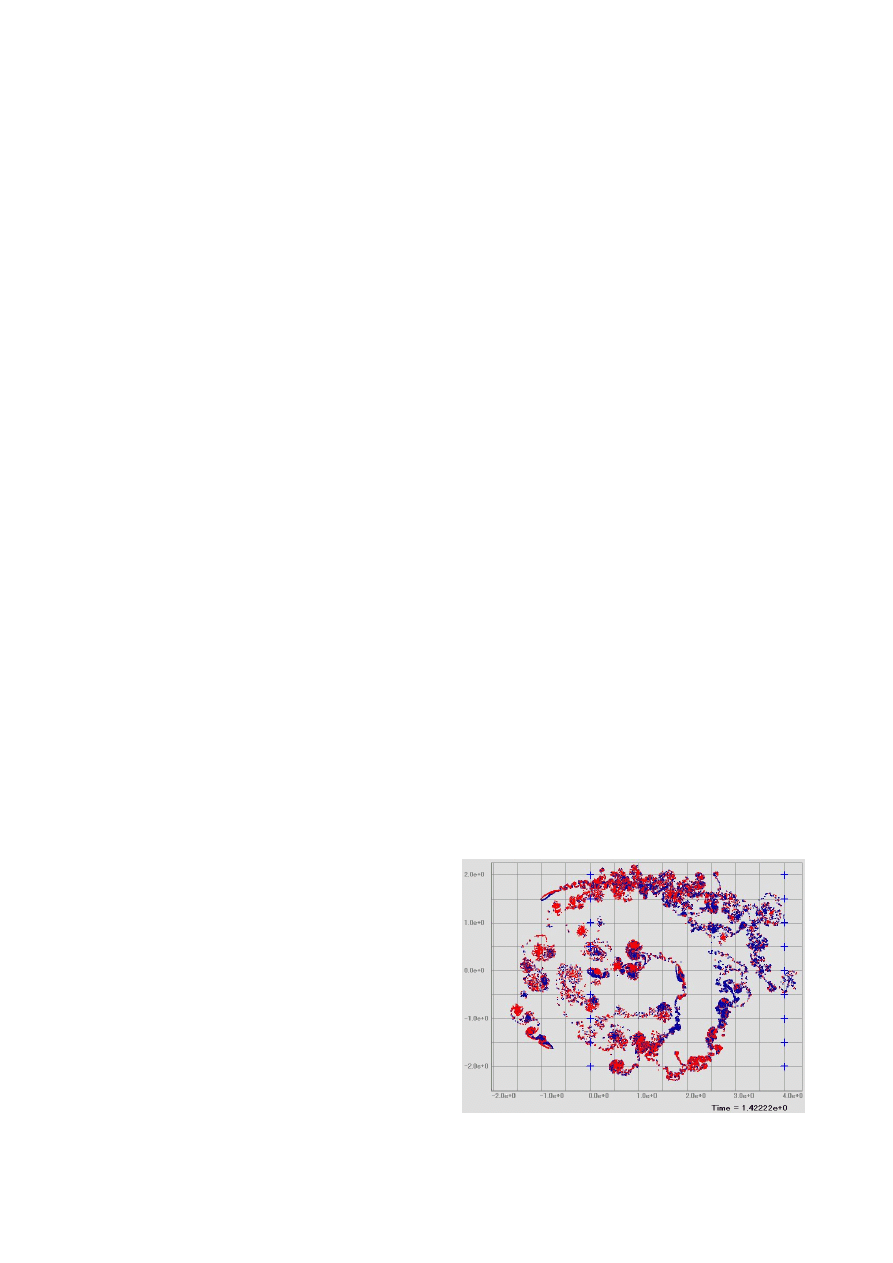
Figure 1 shows flow around a VAWT operated at the
effective power coefficient. The large separated flows
are observed even at the blade in upstream region.
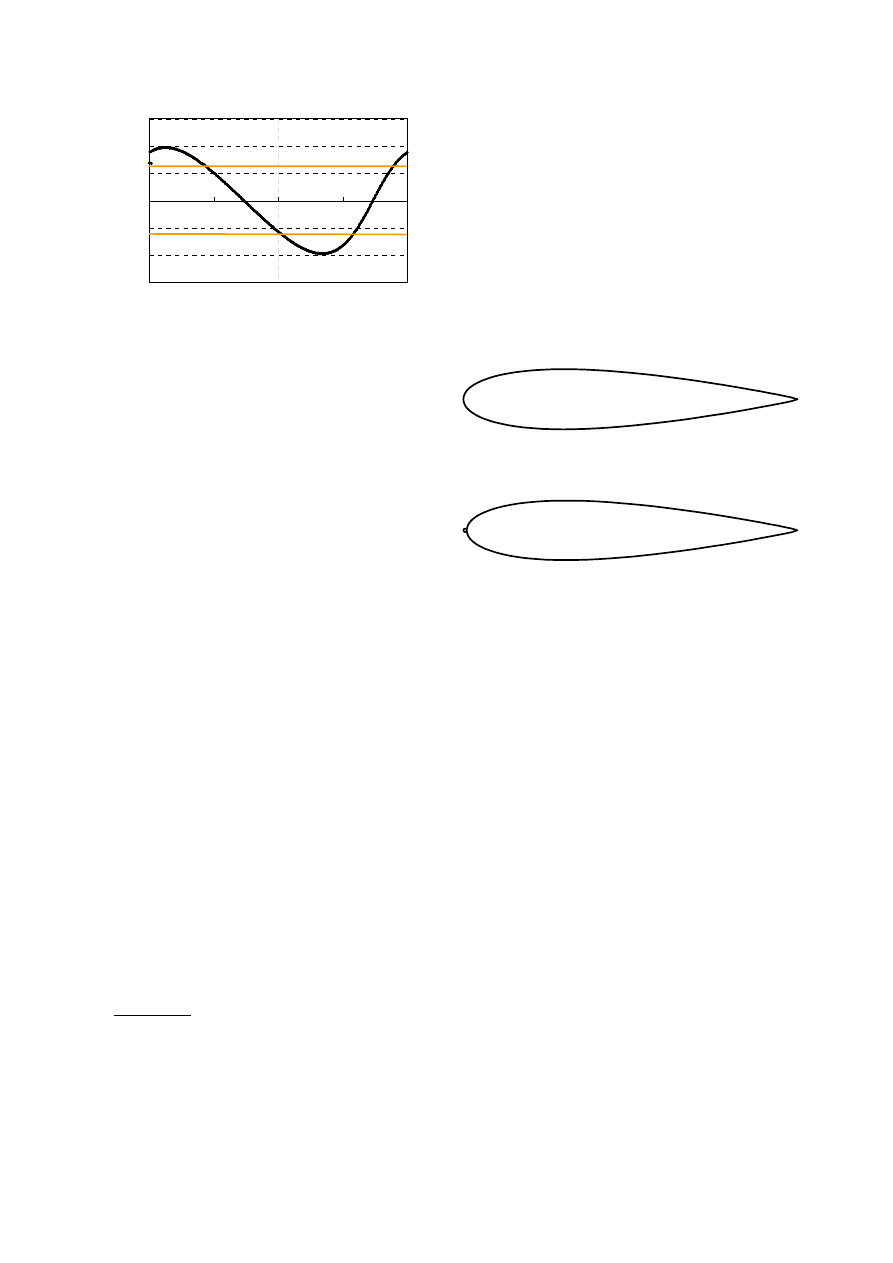
Figure 2 shows the time-evolution of the angle of attack
at the same operation point of Figure 1. This figure
shows the angle of attack of VAWT is over 20 degrees
even at condition of the effective operation. The angle
of attack becomes about 180 degrees at off design point.
In order to reduce the drag of airfoil, symmetrical and
thin airfoils are utilized. In the low-Reynolds number
flow around the symmetric, thin airfoil, large separated
flows occur at angle of attack about 10 degrees. The
separated flows reduce the torque of the VAWT.
The aim of this research is to develop the high
performance vertical axis wind turbines. For this
purpose, we attempted to control to flow separations of
symmetric airfoils with turbulence promoters. In order
to obtain aerodynamic forces and flow pattern around
the airfoil, wind tunnel tests and numerical simulations
were conducted. The surface flows were visualized by
the oil film method, and the flow separations were
simulated by the vortex method. Aerodynamic forces
were also estimated by wind tunnel experiments and
numerical simulations.
Figure 1 Flow field around a VAWT
-30
-20
-10
0
10
20
30
0
90
180
270
360
Rotational Angle [deg]
A
n
g
le
o
f A
ttta
ck
[d
eg
]
Blade1
Figure 2 Time-evolution of angle of attack of blade for
VAWT at the effective operation point
2. Measurement Technique
2.1. Turbulence Promoters
Vortex generators or vortex promoters are used to
control of flow separations of airfoils for airplanes.
Promoters play important roles in improvement
aerodynamic performances. In airplanes, turbulence
promoters are attached at only the one-side (negative-
pressure side) of the airfoils, because the pressure side
and negative-pressure-side are fixed. The separation
angles are delayed without additional drag force with
turbulence promoters. On the other hand, in the case of
VAWT, the negative-pressure side is changed
alternatively during the rotor rotation. Turbulence
promoters of VAWT should be symmetrical shape.
We therefore attempted to use the tripping wire
mounted on the upstream stagnation point. The tripping
wire near the leading edge of airfoil may not generate
large drag force at low angel of attack. Since the
performance of the VAWT depend on the drag at the
low angle of attack, this turbulence promoter is useful
to improve the power coefficient of the VAWT.
In low Reynolds number flow around airfoils,
separation babbles are generated near the front
stagnation point. Then, tripping wire on the leading
edge may also improve the performance of the
symmetric airfoils. The Reynolds number based on the
diameter of the wire and uniform velocity must be
larger than 900. In this condition, the diameter of the
wire is about 0.5 mm or more.
The transition Reynolds number from laminar to
turbulence is defined as follows;
000
,
20
)
(
≥
−
∞
ν
k
t
X
X
U
,
where, X
k
denotes wire mounted position and X
t
denotes the transit point. In the case of flow velocity at
25 m/s, (X
t
-X
k
) is about 12mm. It is required to satisfy
the above condition, the wire must be set to 5 - 6 mm
from the leading edge of the airfoil. This length
corresponds to less than 3 % of the chord length. Since
the length was not so large, the wire was set to the
stagnation point as shown in Figure 3.
NACA 4 digit, symmetrical airfoils are utilized for
the small and moderate scale VAWT. In our laboratory,
straight winged VAWT has been developed with
NACA0018 for the rotor blades. Therefore, in this
research, NACA0018 airfoil was used to estimate the
performance of the turbulence promoters. .Figure 3 (a)
shows the standard airfoil of NACA0018 and Figure 3
(b) shows the NACA0018 with present turbulence
promoter. The diameter of the tripping wire is 0.5 mm
and 1.0 mm, respectively.
(a) without tripping wire
(b) with tripping wire
Figure 3 Schematics of blade for VAWT with and
without turbulence promoter.
2.2 Aerodynamic Force Measurements
Aerodynamic forces were measured by using a low-
noise wind tunnel that has a semi-open test section with
a square test section of 500 mm by 500 mm. The strain
gage typed, three-component axes load cell was utilized.
Pre-calibration was carried out in the test section under
the condition of the actual measurements. The lift and
drag force, (also measured side force, but it was not
estimated), were measured.
2.2 Oil Film Method
Flow visualization was carried out in a small wind
tunnel that has an open test section with a square cross
section of 300 mm by 300 mm. The chord length and
spanwise length of the test airfoil (NACA0018) is 250
mm and 300 mm, respectively. The surface flows were
visualized by using the oil-film method. Powder of
titanium oxide was used for the pigments, and paraffin
was used for base materials. A digital camera was fixed
at 400 mm from the airfoil surface. The resolution of
the camera is 2272 × 1704 pixels. The experiment was
conducted at uniform velocity of 25 m/s, the Reynolds
number of 3.0×10
5
. This condition is equivalent to
developed VAWT is operated at the uniform velocity of
6 m/s and the tip-speed ratio of 4.
The airfoil has end plates of the both side, the
spanwise length between the end plates was 150 mm.
The angle of attack was set from 1 degree to 20 degrees.
2.4 Numerical Simulation
In order to estimate the flow around VAWT, it is
necessary to solve the problem of moving boundary and
large separated flows. Since the vortex method has the
mesh free algorithm, it is suitable to solve the moving
boundary problems such as the flow around VAWT. A
further direction of our research will be to solve
aerodynamic performance of VAWT, vortex methods
are therefore utilized to this investigation. The flow
around the symmetric airfoil with and without the
turbulence promoter was solved by the discrete vortex
methods (VFS Oscillation-2D: College Master Hands).
The surface flow is solved to introduce the vortex
elements in the uniform flow field. The airfoil and
tripping wire were modeled by 80 panels and 114
panels, respectively. The unsteady flow field was
solved at the angle of attack from 1 degree to 20
degrees at Reynolds number of 3.0×10
5
.
3. Results and Discussions
3.1 Aerodynamic Force
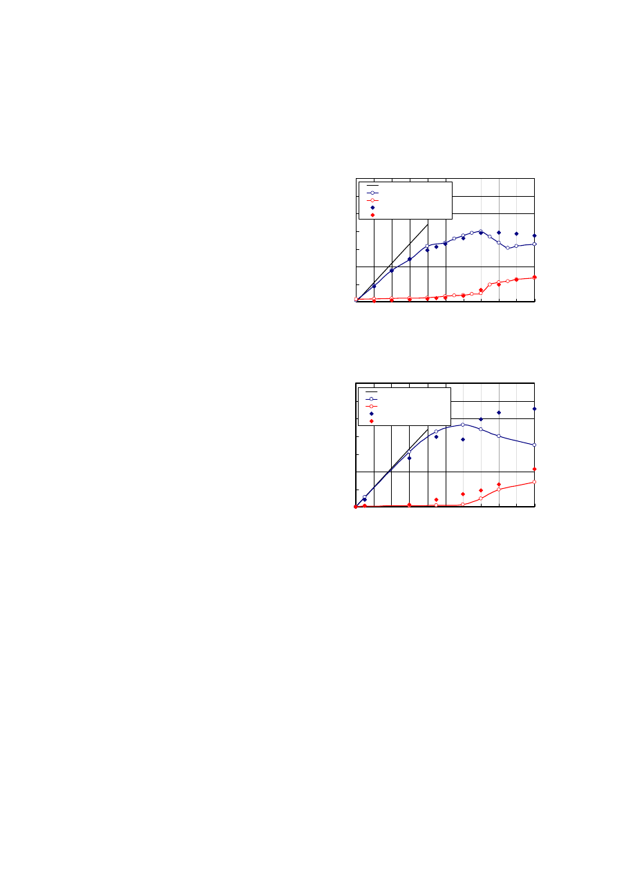
Figure 4 shows the aerodynamic forces of the
symmetric airfoil. Both of the experimental and
numerical results showed that the turbulence promoter
improved the lift of high angle of attack. Moreover it
also improved stall angle. Although the lifting force
from the numerical result was slightly larger than that
of the wind tunnel experiment, the numerical results
were qualitatively agreement with the experimental
results. The results showed the turbulence promotes
improved the aerodynamic performance.
3.2 Flow Field around Airfoil
Figure 5 shows surface flows and distribution of the
vortex elements solved by the discrete vortex method.
In the case of the low angle of attack, surface flows
were almost the same as both of with and without
turbulence promoter.
The flow separation occurred at angel of attack of 9
degrees in the case of the conventional airfoil. And the
large separated flow was observed at angles of attack at
12 - 16 degrees. On the other hand, separations ware
restricted by the turbulence promoter at the high angle
of attack.
The large scale separation occurred at the leading
and trailing edge of the airfoil and strong vorticities
fields was generated at angle of attack of 20 degrees.
The turbulence promoter also worked in this high angle
of attack.
These results indicated that the tripping wire
mounted on the upstream stagnation point as a
turbulence promoter is effective device to improve the
flow properties of high angel of attack airfoil for
VAWT. It may also improve the performance of the
VAWT in actual operation. These devices are important
to develop the high performance VAWT.
0
0.2
0.4
0.6
0.8
1
1.2
1.4
0
2
4
6
8
10 12 14 16 18 20
Angle of Attack [deg]
L
if
t,
D
ra
g
C
o
ef
fi
ci
en
t [
-]
2πsinα
Lift (without tripping wire)
Drag (without tripping wire)
Lift (with tripping wire)
Drag (with tripping wire)
(a) Experiment
0
0.2
0.4
0.6
0.8
1
1.2
1.4
0
2
4
6
8
10 12 14 16 18 20
Angle of Attack [deg]
L
ift,
D
ra
g
C
o
effi
ci
en
t [-
]
2πsinα
Lift (without tripping wire)
Drag (without tripping wire)
Lift (with tripping wire)
Drag (with tripping wire)
(b) Numerical simulation
Figure 4 Aerodynamic forces of NACA0018
controlled with turbulence promoter
4. Conclusions
The performance of turbulence promoter for the
symmetric airfoil at the high angle of attack was
estimated by using the wind tunnel tests and numerical
simulations. The results showed that the tripping wire
near the leading edge improve the aerodynamic
performances. The stall-angel can be controlled by the
turbulence promoter without additional drag at the low
angle of attack. The lift coefficients of high angle of
attack are improved by the tripping wire. It reveals that
the present turbulence promoter is useful to modify the
aerodynamic performance of VAWT.
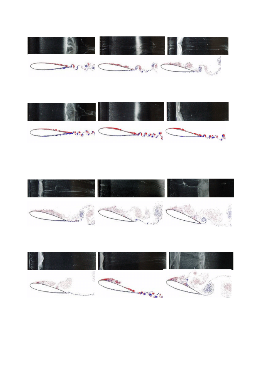
α = 1 α = 6 α = 9
(a) Flow pattern of NACA0018 with turbulence promoter at low angle of attack (Controlled)
α = 1 α = 6 α = 9
(b) Flow pattern of NACA0018 without turbulence promoter at low angle of attack
α = 12 α = 16 α = 20
(c) Flow pattern of NACA0018 with turbulence promoter at high angle of attack (Controlled)
α = 12 α = 16 α = 20
(d) Flow pattern of NACA0018 without turbulence promoter at high angle of attack
Figure 6 Oil film image and distributions of vortex elements around the symmetric airfoil
Wyszukiwarka
Podobne podstrony:
1801 Design Analysis of Fixed Pitch Straight Bladed Vertical Axis Wind Turbines
Control of a 4 leg Inverter for Standalone Photovoltaic Systems
Control Issues Of A Permanent Magnet Generator Variable Speed Wind Turbine
ANALYSIS OF CONTROL STRATEGIES OF A FULL CONVERTER IN A DIRECT DRIVE WIND TURBINE
Control of a 4 leg Inverter for Standalone Photovoltaic Systems
0 Simulation of fatigue failure in a full composite wind turbine blade Shokrieh Rafiee 2006
NASA CR 180678 Calculation of Aerodynamic Characteristics at High Angles of Attack for Airplane Conf
Ebsco Gross The cognitive control of emotio
Control of Redundant Robot Manipulators R V Patel and F Shadpey
epigenetic control of plant dev Nieznany
control of respiration
Causes and control of filamentous growth in aerobic granular sludge sequencing batch reactors
06 Control of respiratory funct Nieznany
Nonlinear Control of a Conrinuously Variable Transmission (CVT) for Hybrid Vehicle Powertrains
Development of wind turbine control algorithms for industrial use
The Hormonal Control of Sexual?velopment
więcej podobnych podstron