Control issues of a Permanent Magnet Generator variable-speed Wind Turbine
A. Haniotis, S. Papathanassiou, A. Kladas* and M. Papadopoulos
Electric Power Division
Department of Electrical & Computer Engineering
National Technical University of Athens
9, Iroon Polytechneiou Street, 15780 Athens, Greece
(*) Tel: (+3)-010-7723765, fax: (+3)-010-7723593, email: kladasel@central.ntua.gr
ABSTRACT: In this paper a prototype of the electrical part of a
variable speed wind turbine is considered, equipped with a
permanent magnet synchronous generator. The modeling of the
generator and power electronics interface is checked with
measurements realized in the prototype under both steady state and
dynamic conditions. Measurements as well as control functions are
performed by using a microprocessor. The outcome of the
simulation and experimental work are actually utilized in the
development of a 25 kW wind turbine, in the frame of a research
project.
Keywords: dynamic response, microprocessor based control,
permanent magnet, synchronous generator, wind turbine.
I. INTRODUCTION
The control of wind turbine systems is a complicated task due
to the stochastic nature of available energy by the wind.
Moreover often conflicting requirements are involved, such as
the low cost and reduced stresses [14], on the one hand, and
the good output power quality and dynamic characteristics on
the other [9],[10]. In this paper variable speed wind turbines
are considered, equipped with permanent magnet generators
[7],[8]. The examined wind turbines are multi-polar in order
to avoid switch-gears, exhibiting the well-known weight and
reliability problems [6].
In order to achieve variable speed operation, a power
electronics converter stage is necessary to connect the
generator to the grid [1],[2]. The system analysis in such
cases involves models for the generator [3],[4],[5], the static
converter [2],[12] and the grid [9].
In this paper a 2 kW prototype of the electrical part of such a
variable speed wind turbine is considered, equipped with a 24
pole permanent magnet synchronous generator. The modeling
of the generator and power electronics interface is presented
and checked with measurements realized in the prototype,
both in the steady state and in dynamic conditions.
Measurements as well as control functions are performed by a
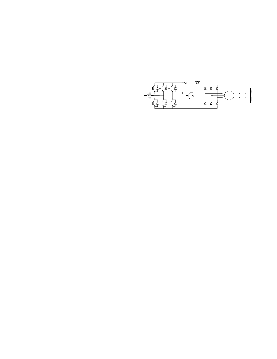
SG
Diode
Rectifier
Voltage Source
Inverter
Fig. 1. Subsystems of the electrical part of a typical permanent magnet
generator variable speed wind turbine system
microprocessor [15].
The outcome of the simulation and experimental work are
actually utilized in the development of a low cost 25 kW wind
turbine, in the frame of a research project funded by the
Greek Secretariat for Research and Technology.
II. SUBSYSTEMS AND MODELING
The basic components of a variable speed wind turbine
system are shown in Fig. 1. In this figure, it may be noted that
there is no gearbox to increase the speed of the generator
rotor. This is due to the machine multiple pole structure, in
order to achieve reasonable electrical frequencies for low
rotor speed. In the case considered 100 poles are needed (100
rpm) for the 25 kW sized machine while 24 poles (400rpm)
were adopted for the prototype.
The static converter shown in Fig. 1 consists of an
uncontrolled 3-phase diode rectifier, a DC/DC boost
converter, a 3-phase PWM voltage source inverter and
possibly a step-up transformer.
A.
Aerodynamic part and control reference
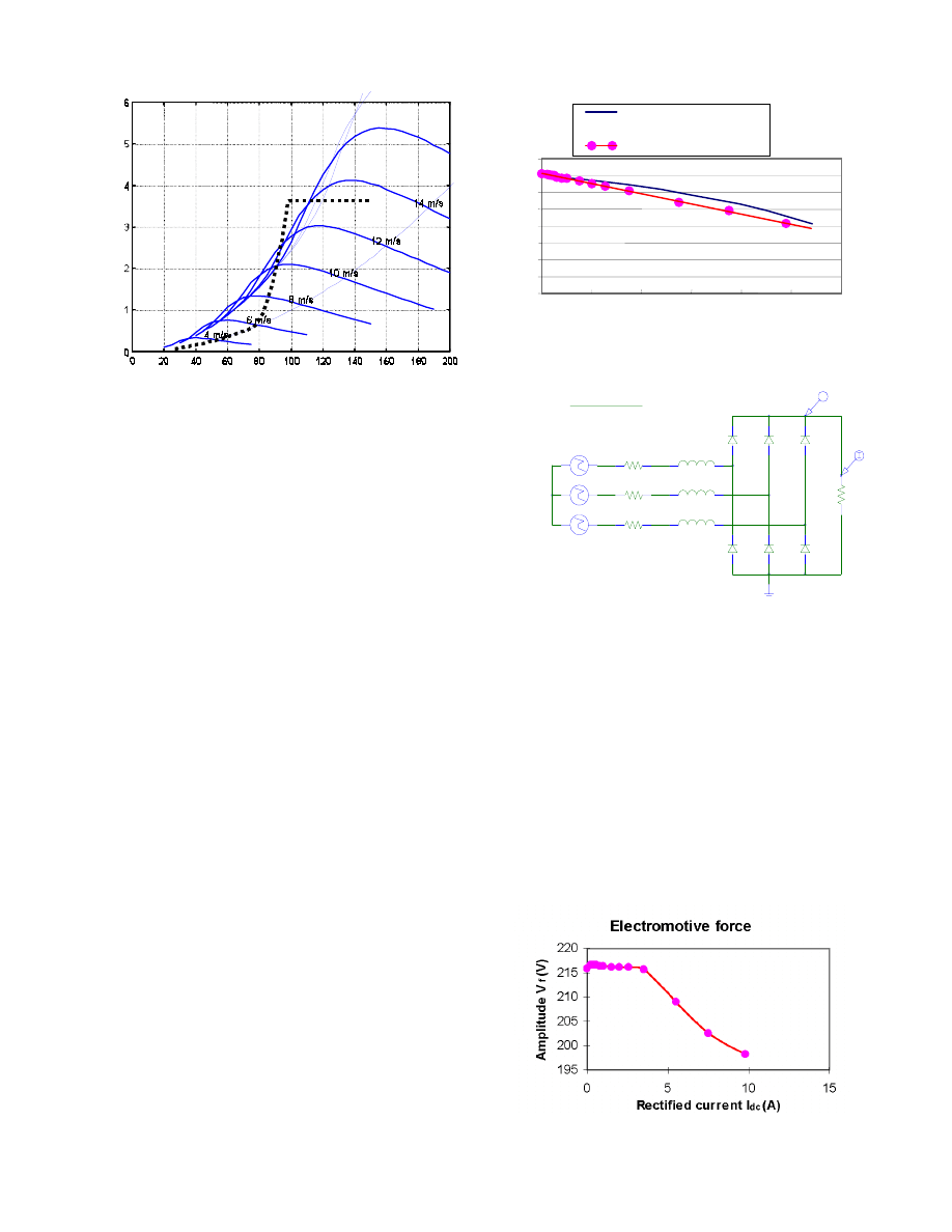
Aerodynamic analysis of the wind turbine blades provided the
characteristics shown in Fig.2. The continuous curves show
variations of the rotor torque with rotor speed, for a given
wind speed.
The dotted line is the proposed reference for the control
system and can be divided into three main parts associated to
different control operations: the leftmost part, with low
inclination, corresponds to the maximum power points for
every wind speed. The median part, with high inclination,
prevents the turbine from over-speed, thus protecting it by
using the stall effect. The rightmost part corresponds to the
situation that the machine cannot deliver more torque, so an
external braking system is needed for shutting down the
system. Obviously, the control action should avoid such a
situation, that is why the paper is devoted to the
implementation of the first two parts of the reference.
Ro
to
r To
rq
u
e
(
kN•
m
)
Fig. 2. Aerodynamic part torque-speed characteristics for different wind
speeds and proposed control reference
The characteristics shown in Fig. 2 are static corresponding to
the steady state of the aerodynamic part. The wind speed is
practically never steady. In fact, it is quite variable,
depending on the wind characteristics of the specific place.
So it is very important both in the design and implementation
of the control system to consider the dynamic behavior.
B.
Electrical part
The actual configuration used in the laboratory did not
include the shown in Fig. 1. In our case the generator’s
inductance was used for voltage boosting and filtering.
Moreover, the voltage source inverter and the grid have been
represented by a convenient resistive load controlled by a
chopper.
The rectified output of the generator prototype is quite similar
to the ones of a direct current machine. This is shown in
Fig. 3 comparing the theoretical prediction of such a
characteristic by using finite element simulation [8]. This
form of behavior involves simple calculations for
representation of the boost converter.
The generator model used in the electric circuit analysis
considered sinusoidal electromotive forces. This provides
acceptable accuracy for the generator representation while
necessitating reduced calculation means [7].
To ensure accuracy, a three phase equivalent circuit has been
used together with a rectifier and a resistive load, and both
measured and simulated waveforms have been compared. The
circuit illustrated in Fig. 4 allowed for both fundamental and
higher harmonics analysis.
The case of low load condition has been simulated and the
computed results by the different models are compared to
measurements. The measured time variations of the phase
current and voltage are shown in figures 6c and 7c,
respectively. Both current and voltage waveforms are
distorted due to the reactive power effect of the rectifier.
The simulated results by the fundamental component model
for the phase current and voltage in the machine in this case
y = -15.12x + 356.76
0
50
100
150
200
250
300
350
400
0
2
4
6
8
10
12
I
dc
(A)
V
dc
(V)
Simulated characteristic
Experimental results
Fig. 3. I-V characteristics of the rectified output of the synchronous
permanent magnet generator
PARAMETERS:
RL
200Ω
L1
19.134mH
L2
19.134mH
19.134mH
L3
R1
2.872Ω
R3
2.872Ω
R2
2.872Ω
+
-
FILE=phase1.txt
V1
+
-
FILE=phase2.txt
V2
+
-
FILE=phase3.txt
V3
{RL}
RL
V
Fig. 4. Three phase equivalent circuit used in all simulations of the
permanent magnet synchronous generator
are shown in figures 6a and 7a, respectively.
While the simulated current is in very good agreement with
the measured one by using this model, the voltage is not
represented properly. This implies that fundamental
component model cannot be very accurate in voltage
prediction as it neglects the higher harmonics .
Higher harmonics model is in very good agreement with the
measured waveforms for both phase current (figure 6b) and
voltage (figure 7b). In these figures, even the spikes due to
diode recovery are efficiently represented.
At high load conditions the current has less higher harmonic
content but the voltage is even more distorted.
Fig. 5. Reduction of fundamental electromotive force to match rms electrical
values in fundamental component model
Rotor speed (rpm)
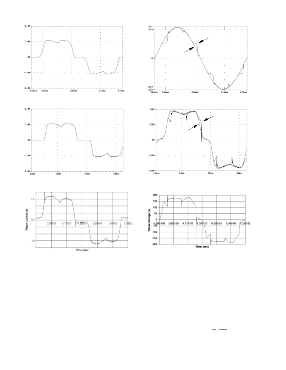
a
b
c
Fig. 6: Phase current of the permanent magnet synchronous machine at
low load conditions
a: simulated by the fundamental component model
b: simulated by the higher harmonics model
c: measured
Higher harmonics model provides simulated waveforms,
which are almost identical to the measured ones.
Furthermore, this model needs no adjustment of
electromotive force’s amplitude to represent efficiently rms
values, and can be easily used for lower machine speeds.
On the contrary the results in fundamental analysis showed
the need for reduction of electromotive force to match rms
electrical values. Fig. 5 shows the amount of reduction in full
speed operation.
a
b
c
Fig. 7: Phase voltage of the permanent magnet synchronous
machine at low load conditions
a: simulated by the fundamental component model
b: simulated by the higher harmonics model
c: measured
C.
Mechanical part
In the case of the simpler representation of the mechanical
part by a concentrated mass with moment of inertia J rotating
at angular velocity ω
r
, the governing equation is:
dt
d
P
J
T
T
r
e
m
ω
=
−
2
(1)
No load
No load
Low load
Low load
T
m
+
Js
1
T
m
-T
e
ω
1
1
+
s
T
f
T
e
-
ω-Τ
ω
ref
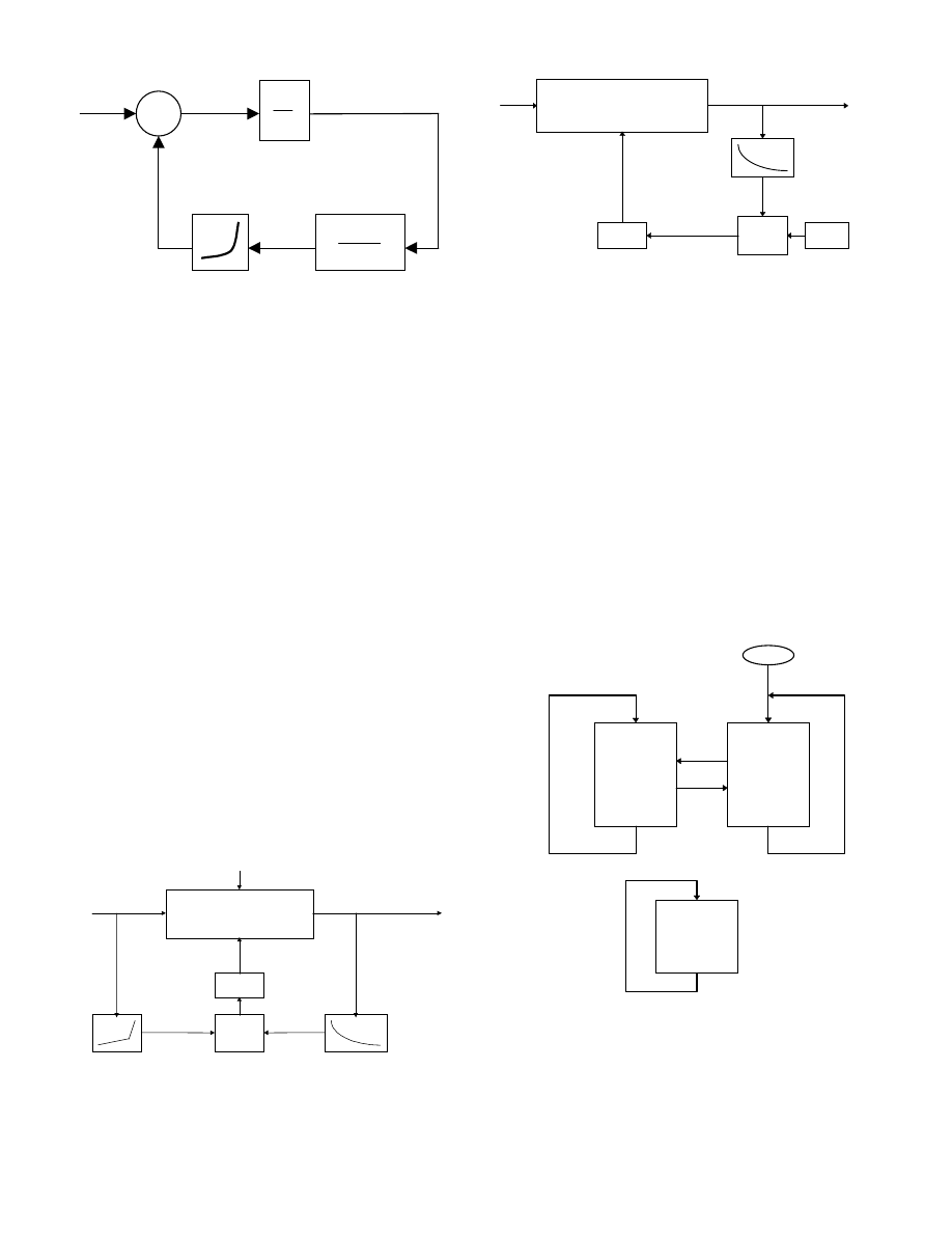
Fig. 8. Speed control system block diagram
where P is the number of poles, T
m
is the mechanical torque
on the shaft and T
e
the electromagnetic torque
In order to obtain a control without oscillations, a low-pass
filter must be included in the rotor speed feedback path of the
control, as shown in Fig. 8. Its purpose is to attenuate speed
oscillations, which otherwise would be reflected on the
generator torque, degrading the output power quality and
contributing to the variability of the mechanical torques. Thus
a convenient selection of T
f
is very important [7].
III. CONTROL SYSTEM AND MEASUREMENTS
After constructing the circuits and predicting the electrical
behavior, a control program is needed to evaluate the data
measured and act as necessary to bring the system to the
desired working point [11]. In our case two loops are
working: A current control loop associating the reference
torque-speed characteristic to a convenient generator current -
speed characteristic as shown in Fig. 9 has been introduced.
Moreover a voltage - loading control loop has been adopted
illustrated in Fig. 10.
The current control loop draws monitors the electrical power
from the generator in order to achieve the correct
combination of power and electrical frequency corresponding
to the optimum operation of the aerodynamic part (reference
in Fig. 2). It is a PI controller with a low pass filter and a non-
linear reference.
f
V
C
I
1
D
1
(PWM1)
Low pass
filter
τ = 9250μs
(95%)
Σ
K
1
(I
1
-I
1
΄)
Control reference
Current -- speed
I
1
΄
I
1
= E(f)/R
G
+ (D
1
-1)V
C
/R
G
ΔI
1
/ΔV
C
= (D
1
-1)/R
G
[1-exp(-tR
G
/L)]
ΔI
1
/ΔE(f) = 1/R
G
[1-exp(-tR
G
/L)]
ΔI
1
/ΔD
1
= V
C
/R
G
[1-exp(-tR
G
/L)]
Fig. 9. Schematic diagram of synchronous generator
current -speed control subsystem
D
2
(PWM2)
I
2
V
C
Low - pass
filter with
τ < 500μs
(25%)
Σ
K
2
(V
C
-V
C
΄)
Constant of
comparison
V
C
΄
V
C
= I
2
R
L
/D
2
Δ
V
C
/
ΔI
2
= (R
L
/D
2
) [1-exp(-tD
2
/R
L
C)]
ΔV
C
/ΔD
2
= -(R
L
I
2
/D
2
2
) [1-exp(-tD
2
/R
L
C)]
Fig. 10. Schematic diagram of capacitor voltage -loading control
subsystem
The power drawn from the generator charges the filtering
capacitors. The voltage control loop takes care of monitoring
the accumulated power in the capacitors to the load.
As the capacitors are charged, their voltage increases. This PI
controller shown in Fig. 10 filters the measurement and
compares the result with a pre-defined constant. Then
capacitors are discharged through the load adjusted by a
PWM controlled IGBT.
The program consists of two branches as shown in Fig. 11:
the main program and automatic control. In the main program
the user may review measurements and alter state variables
[15]. By pressing the ‘C’ key on the PC keyboard one may
start the automatic control, where the two aforementioned
loops cooperate and monitoring is disabled due to speed
problems. Special care is taken at extreme circumstances, i.e.
in case of an over-voltage condition.
BEGIN
MAIN
PROGRAM
AUTOMATIC
CONTROL
‘C’
‘R’
PERIOD
COUNTER
Fig. 11. Flow chart of microprocessor program
IV. RESULTS AND DISCUSSION
The experimental set-up comprises the permanent magnet
synchronous generator prototype consisted of 24 poles,
illustrated in Fig. 12. The shaft torque is controlled by using a
dc machine torque-meter simulating the aerodynamic part of
the wind- turbine. The maximum rotating speed adopted for
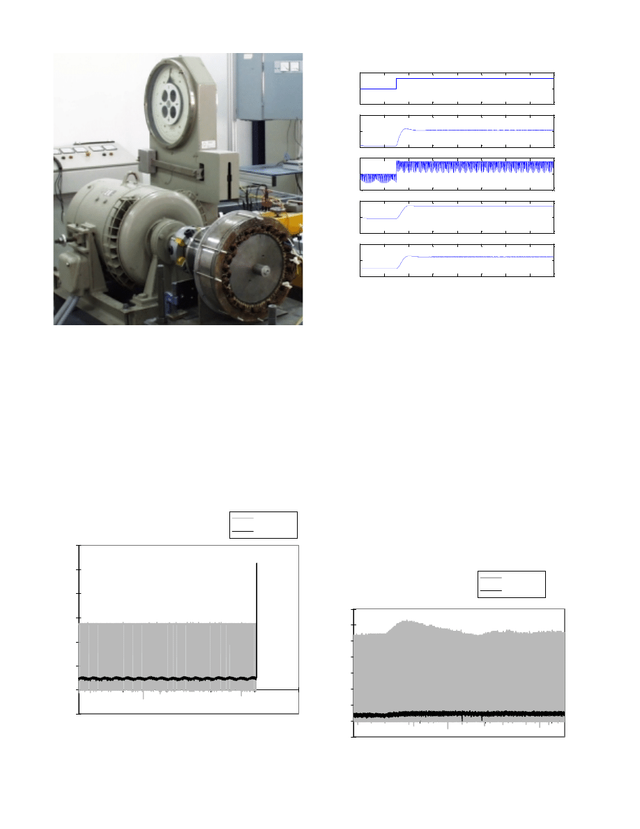
Fig. 12. Experimental set-up showing the 2 kW permanent magnet
synchronous machine prototype.
the experiments was 400 rpm. This system enables also
dynamic analysis by applying convenient torque steps through
appropriate control of the four quadrant converter supplying
the dc torque-meter.
Fig. 13 shows the capacitor voltage (Channel 1 - 550V) and
generator rectified current ripples (Channel 2 - 5A) at steady
state. This figure illustrates the very good steady state
characteristics of the system.
The dynamic behavior of the system is of equally great
importance. The simulated time responses for the rotor
angular velocity ω
m
, mechanical torque T
m
, electrical Torque
T
e
and generated power P
e
, in case of a step up in wind speed
T=3.5kgm and f=64Hz
-1
0
1
2
3
4
5
6
0
0,01
0,02
0,03
0,04
0,05
Time (s)
Channel 1
Channel 2
Fig. 13. Measured steady state system ripples (capacitor voltage and
generator current for 3.5 kg.m torque and 64Hz frequency)
0
2
4
6
8
10
12
14
16
6
7
8
V
w
(m
/s
)
0
2
4
6
8
10
12
14
16
330
340
350
ω
m
(ra
d/
s)
0
2
4
6
8
10
12
14
16
1
1.5
2
T
m
(k
g•
m
)
0
2
4
6
8
10
12
14
16
1
1.5
2
T
e
(k
g•
m
)
0
2
4
6
8
10
12
14
16
400
600
800
P
e
(W
)
time(s)
Fig. 14. Simulated electromechanical time response for step up wind
speed variation
V
w
are shown in Fig. 14. This figure shows that the time
constant involved is approximately 2 seconds, which is in
good agreement with the time responses of the measured
capacitor voltage and generator current for a step increase in
rotor torque, given in Fig. 15.
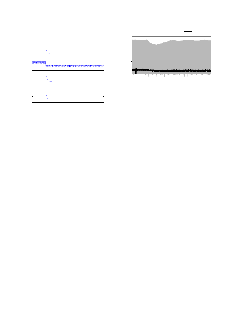
The agreement between simulated and measured time
responses can be observed in Figs. 16 and 17 showing the
same results in case of step down wind speed variation.
V. CONCLUSION
The design, construction and testing of a control system for
synchronous permanent magnet generator wind turbines has
been presented. This system ensures produced power
optimization as well as overspeed protection in case of high
wind speeds. Its performance has been checked by means of a
2 kW experimental set-up. The proposed system provides
excellent steady state characteristics and adequate time
response to step torque variations.
T:1.5kgm->1.87kgm
and f:41Hz->56Hz
-0,5
0
0,5
1
1,5
2
2,5
3
3,5
0
5
10
15
Time (s)
Channel 1
Channel 2
Fig. 15. Measured system time response for step up torque (capacitor
voltage and generator current time variations)
0
2
4
6
8
10
12
14
16
7
8
9
V
w
(m
/s
)
0
2
4
6
8
10
12
14
16
340
350
360
ω
m
(rad/
s)
0
2
4
6
8
10
12
14
16
1
2
3
T
m
(k
g•
m
)
0
2
4
6
8
10
12
14
16
1.5
2
2.5
T
e
(k
g•
m
)
0
2
4
6
8
10
12
14
16
600
800
1000
P
e
(W
)
time(s)
Fig. 16. Simulated electromechanical time response for step down wind
speed variation
VI. AKNOWLEDGEMENT
The authors express their gratitude to the General Secretariat for Research
and Technology of Greece for co-financing this work under SYN Grant
No 96SYN24.
VII. REFERENCES
[1]
“Motion control with permanent magnet AC machines”, T. M.
Jahns, IEEE Proceedings, Vol. 82, No 8, 1994,
pp. 1241-1252.
[2]
Power Electronics-Converters, Applications and Design, N. Mohan,
T. M. Undeland, W. P. Robbins, Wiley, 1995.
[3]
“Modeling and experimental verification of the performance of a
skew mounted permanent magnet brushless dc motor drive with
parameters computed from 3D-FE magnetic field solutions”,
M.A. Alhamadi, N. A. Demerdash, IEEE Trans. on Energy
Conversion, Vol. 9, no 1, 1994, pp. 26-35.
[4]
Marchand C., Ren Z., Razek, A., “ Torque optimization of a buried
permanent magnet synchronous machine by geometric modification
using FEM”, EMF’94 International Conference, Leuven, Belgium,
1994, pp. 53-56.
[5]
“Optimization procedure of surface permanent magnet synchronous
motors”, T. Higuchi, J. Oyama, E. Yamada, E. Chiricozzi,
F. Parasiliti, M. Villani, IEEE Trans. on Magnetics, Vol. 33, no 2,
1997, pp. 1943-6.
[6]
Kladas A., Papadopoulos M., Tegopoulos J., “Multipole permanent
magnet generator design for gearless wind power applications”,
ICEM’98, Istanbul, Turkey, 1998, pp. 2055-9.
[7]
Aliprantis D., Papathanassiou S., Papadopoulos M., Kladas A.,
"Modeling and control of a variable-speed wind turbine equipped
with permanent magnet synchronous generator", ICEM'2000,
Helsinki, Finland, August 2000, pp. 558-562.
[8]
“Neural Network Approach compared to Sensitivity Analysis based
on Finite Element Technique for Optimization of Permanent
Magnet Generators”, G. Tsekouras , S. Kiartzis , A. Kladas,
J. Tegopoulos, IEEE Trans. on Magnetics, Vol. 37, no 5/1, 2001,
pp. 3618-3621.
[9]
Grid Integration of Wind Energy Conversion Systems, S. Heier,
Wiley, 1998.
[10]
“Damping of power-angle oscillations of a permanent magnet
synchronous generator with particular reference to wind power
applications”, A. J. G. Westlake, J. R. Burnby, E. Spooner, IEE
Proceedings - Electric Power Applications, Vol. 143, No 3, 1996,
pp. 269-280.
T:2.55kgm->2.05kgm
and f:61Hz->59Hz
-0,5
0
0,5
1
1,5
2
2,5
3
0
5
10
15
Time (s)
Channel 1
Channel 2
Fig. 17. Measured system time response for step down torque (capacitor
voltage and generator current time variations)
[11]
Automatic Control Systems", B. C. Kuo, 7th Edition, Prentice
Hall International Editions.
[12]
“Implementation of wind-turbine controllers”, D. J. Leith,
W. E. Leithead, Int. Journal on Control, Vol. 66, no 3, 1997,
pp. 349-380.
[13]
“Design and performance evaluation of a fuzzy-logic-based
variable-speed wind generation system”, M. G. Simoes, B. K. Bose,
R. J. Spiegel, IEEE Trans. on Industry Applications, Vol. 33, no 4,
1997, pp. 956-965.
[14]
“Dynamic Behavior of Variable Speed Wind Turbines under
Stochastic Wind”, S. Papathanassiou, M. Papadopoulos, IEEE
Trans. on Energy Conversion, Vol. 14, No. 4, Dec. 1999, pp. 1617-
1623.
[15]
MICROCHIP: Complete PIC18C Reference Manual, 2001.
VIII. BIOGRAPHIES
Antonios E. Chaniotis (e-mail: achan@cc.ece.ntua.gr) was born in
Greece, in 1976. He received the Diploma in Electrical and Computer
Engineering from the National Technical University of Athens in 2001
where he follows post-graduate studies. His research interests include
microprocessor based power control systems as well as analysis of
generating units by renewable energy sources.
Stavros A. Papathanassiou (e-mail: st@power.ece.ntua.gr) was born in
Thesprotiko, Greece, in 1968. He received the Diploma in Electrical
Engineering from the National Technical University of Athens (NTUA),
Greece, in 1991 and the Ph.D. degree in 1997 from the same University.
His research mainly deals with electric machines and drives, wind turbine
modeling and control and the analysis of autonomous power systems with
large wind penetration.
Antonios G. Kladas (e-mail: kladasel@central.ntua.gr) was born in
Greece, in 1959. He received the Diploma in Electrical Engineering from
the Aristotle University of Thessaloniki, Greece in 1982 and the DEA and
Ph.D. degrees in 1983 and 1987 respectively from the University of Pierre
and Marie Curie (Paris 6), France. He served as Associate Assistant in the
University of Pierre and Marie Curie from 1984-1989. During the period
1991-1996 he joined the Public Power Corporation of Greece, where he
was engaged in the System Studies Department. Since 1996 he joined the
Department of Electrical and Computer Engineering of the National
Technical University of Athens, where he is now Associate Professor. His
research interests include transformer and electric machine modeling and
design as well as analysis of generating units by renewable energy sources
and industrial drives.
Michael P. Papadopoulos (e-mail: mpapad@power.ece.ntua.gr) was
born in Ioannina, Greece, in 1932. He received the Diploma in Electrical
and Mechanical Engineering in 1956 and the Ph.D. degree in 1974 from
the National Technical University of Athens (NTUA), Greece. In 1956 he
joined the Public Power Corporation of Greece, where he was engaged in
the planning, design, operation and control of rural and urban distribution
networks, as well as in the utilisation of electric energy. He is currently
Em. Professor in NTUA and member of the Regulatory Authority for
Energy of Greece.
Wyszukiwarka
Podobne podstrony:
więcej podobnych podstron