
SAIA-Burgess Electronics Ltd.
SAIA
®
Process Control Devices
Programming tools for MS WINDOWS
The FUPLA and the KOPLA
function families
PG 4 Version 1.3
Edition 26/749 E1 - 04.96
SAIA-Burgess Electronics Ltd. 1996-97 all rights reserved
Subject to technical changes

FUPLA and KOPLA functions
Contents
26/749 E1
(P4-749-E.DOC)
SAIA AG
Page 4-1
Contents
In this manual all functions of the standard FUPLA and the KOPLA are
desrcibed. This manual represents the chapter 4.4 and 4.5 of the manual
"Programming Package based on WINDOWS - PG4" (26/748 E).
The descriptions of the functions are normally identical to the "Infos" of
the functions on the screen.
Overview over the function families:
4.4
The function families of the FUPLA
4.4.1
Binary
Binary functions
4.4.2
Flip-Flop
Flip-Flops
4.4.3
Counter
Counters
4.4.4
Time related
Time related functions
4.4.5
Blinker
Blinker
4.4.6
Integer
Integer arithmetic
4.4.7
Floating Point
Floating point arithmetic
4.4.8
Converter
Converters (binary-integer-floating point)
4.4.9
Indirect
Indirect addressing
4.4.10
Move-In/-Out
Move Data
4.4.11
Display
Displays
4.4.12
Graftec
GRAFTEC functions
4.4.13
Special
Special functions
4.4.14
Analog module
Read in and output analogue values
4.4.15
Regulation
Regulation (PID control).
4.4.16
User definable
User-defined functions
4.4.17
Communication
Serial communications (mode "D")
4.5
The function families of the KOPLA (Ladder diagram)

FUPLA and KOPLA functions
Overview
26/749 E1
(P-4400-E.DOC)
SAIA AG
Page 4-5
4.4 The function families of the FUPLA
Overview of functions in the individual function families
(arranged according to function and usage *))
4.4.1
Binary functions
4.4.1.1
And 2-10 inputs
4.4.1.2
Or 2-10 inputs
4.4.1.3
Xor 2-10 inputs
4.4.1.4
Move
4.4.1.5
Dynamize
4.4.1.6
High
4.4.1.7
Low
4.4.1.8
Not connected
4.4.1.9
Mux binary selection
4.4.1.10
Mux integer selection
4.4.1.11
Demux binary selection
4.4.1.12
Demux integer selection
4.4.1.13
I/O indirect
4.4.1.14
Flag indirect
4.4.1.15
Even 2-10 inputs
4.4.1.16
Odd 2-10 inputs
4.4.2
Flip-Flops
4.4.2.1
Toggle
4.4.2.2
Type D
4.4.2.3
Type RS dynamized
4.4.2.4
Type SR dynamized
4.4.2.5
Type JK
4.4.2.6
Type RS clocked
4.4.2.7
Type SR clocked
4.4.2.8
Type RS
4.4.2.9
Type SR
*)
In FUPLA all functions are automatically arranged in
alphabetical order.

Overview
FUPLA and KOPLA functions
Page 4-6
SAIA AG
(P-4400-E.DOC)
26/749 E1
4.4.3
Counters
4.4.3.1
Up with preset
4.4.3.2
Down with preset
4.4.3.3
Up
4.4.3.4
Up/down with preset
4.4.3.5
Up/down with preset and clear
4.4.4
Time related - Time function elements
4.4.4.1
On delay
4.4.4.2
Store delay
4.4.4.3
Exclusive pulse
4.4.4.4
Off delay
4.4.4.5
On/off delay
4.4.4.6
Off delay with reset
4.4.4.7
Pulse
4.4.4.8
Chronometer
4.4.4.9
Time (Hardware clock)
4.4.4.10
Start delay
4.4.5
Blinker
4.4.5.1
Blink delay T
4.4.5.2
Blink delay T0/T1
4.4.5.3
Sample

FUPLA and KOPLA functions
Overview
26/749 E1
(P-4400-E.DOC)
SAIA AG
Page 4-7
4.4.6
Integer arithmetic
4.4.6.1
Add
4.4.6.2
Subtract
4.4.6.3
Multiply
4.4.6.4
Divide
4.4.6.5
Square root
4.4.6.6
Average
4.4.6.7
Constant
4.4.6.8
Absolute
4.4.6.9
Bitwise and
4.4.6.10
Bitwise or
4.4.6.11
Bitwise exclusive or
4.4.6.12
Bitwise invert
4.4.6.13
Is equal to
4.4.6.14
Is greater or equal to
4.4.6.15
Is greater than
4.4.6.16
Is smaller or equal to
4.4.6.17
Is smaller than
4.4.6.18
Is zero
4.4.6.19
Limit
4.4.6.20
Maximum
4.4.6.21
Minimum
4.4.6.22
Move
4.4.6.23
Move when enabled
4.4.6.24
Move and store
4.4.6.25
Switch
4.4.6.26
Multiplexer with binary selection
4.4.6.27
Multiplexer with integer selection
4.4.6.28
Demultiplexer with binary selection
4.4.6.29
Demultiplexer with integer selection
4.4.6.30
Shift left
4.4.6.31
Shift right
4.4.6.32
Rotate left
4.4.6.33
Rotate right
4.4.6.34
Register indirect
4.4.6.35
T/C indirect
4.4.6.36
Not connected

Overview
FUPLA and KOPLA functions
Page 4-8
SAIA AG
(P-4400-E.DOC)
26/749 E1
4.4.7
Floating point arithmetic
4.4.7.1
Add
4.4.7.2
Subtract
4.4.7.3
Multiply
4.4.7.4
Divide
4.4.7.5
Square root
4.4.7.6
Average
4.4.7.7
Constant
4.4.7.8
Absolute
4.4.7.9
Sine
4.4.7.10
Cosine
4.4.7.11
ARC tangent
4.4.7.12
Natural exponent
4.4.7.13
Natural log
4.4.7.14
Is equal to
4.4.7.15
Is greater or equal to
4.4.7.16
Is greater than
4.4.7.17
Is smaller or equal to
4.4.7.18
Is smaller than
4.4.7.19
Is zero
4.4.7.20
Limit
4.4.7.21
Maximum
4.4.7.22
Minimum
4.4.7.23
Move
4.4.7.24
Move when enabled
4.4.7.25
Move and store
4.4.7.26
Switch
4.4.7.27
Multiplexer with binary selection
4.4.7.28
Multiplexer with integer selection
4.4.7.29
Demultiplexer with binary selection
4.4.7.30
Demultiplexer with integer selection
4.4.7.31
Not connected

FUPLA and KOPLA functions
Overview
26/749 E1
(P-4400-E.DOC)
SAIA AG
Page 4-9
4.4.8
Converters (binary-integer-floating point)
4.4.8.1
Bin to int 1-8
4.4.8.2
Bin to int 1-24
4.4.8.3
Bin to int quick (PCD format)
4.4.8.4
Bin to int reverse quick (PCA format)
4.4.8.5
Int to bin 1-8
4.4.8.6
Int to bin 1-24
4.4.8.7
Int to bin quick (PCD format)
4.4.8.8
int to bin reverse quick (PCA format)
4.4.8.9
BCD to int
4.4.8.10
BCD to int quick (PCD format)
4.4.8.11
BCD to int reverse quick (PCA format)
4.4.8.12
Int to BCD
4.4.8.13
Int to BCD quick (PCD format)
4.4.8.14
Int to BCD reverse quick (PCA format)
4.4.8.15
1-bit to int with shift
4.4.8.16
1-bit to int LSB
4.4.8.17
Int to 1-bit with shift
4.4.8.18
Int LSB to 1-bit
4.4.8.19
Float to int
4.4.8.20
Int to float
4.4.9
Indirect addressing
4.4.9.1
Copy to outputs
4.4.9.2
Read from inputs
4.4.9.3
Copy to flags
4.4.9.4
Read from flags
4.4.9.5
Copy to registers integer
4.4.9.6
Read from registers integer
4.4.9.7
Copy to registers float
4.4.9.8
Read from registers float
4.4.9.9
Copy to Timer/Counter
4.4.9.10
Read from Timer/Counter
4.4.9.11
Timer with indirect addressing
4.4.9.12
Counter with indirect addressing
4.4.9.13
Read logic state from Timer/Counter

Overview
FUPLA and KOPLA functions
Page 4-10
SAIA AG
(P-4400-E.DOC)
26/749 E1
4.4.10
Move Data
4.4.10.1
Move-In Bit
4.4.10.2
Move-Out Bit
4.4.10.3
Move-In Nibble
4.4.10.4
Move-Out Nibble
4.4.10.5
Move-In Digit
4.4.10.6
Move-Out Digit
4.4.10.7
Move-In Byte
4.4.10.8
Move-Out Byte
4.4.10.9
Move-In Word
4.4.10.10
Move-Out Word
4.4.11
Displays
4.4.11.1
Display module PCA2.D12
4.4.11.2
Display module PCA2.D14
4.4.11.3
Display module PCD2.F510 for numeric displays
4.4.11.4
Display module PCD2.F510 for text displays
4.4.12
GRAFTEC functions
4.4.12.1
Load timer
4.4.12.2
Load timer conditional
4.4.12.3
Load counter
4.4.12.4
Load counter conditional
4.4.12.5
Increment counter
4.4.12.6
Decrement counter
4.4.12.7
Timer is zero
4.4.12.8
Counter is zero
4.4.12.9
End of transition
4.4.12.10
Wait time
4.4.12.11
Wait pulse
4.4.13
Special functions
4.4.13.1
Watch dog
4.4.13.2
Watch dog enable

FUPLA and KOPLA functions
Overview
26/749 E1
(P-4400-E.DOC)
SAIA AG
Page 4-11
4.4.14
Analog modules
4.4.14.1
PCD2.W1
Analog Input module PCD2.W1 (12 Bit)
4.4.14.2
PCD2.W2
Analog Input module PCD2.W2 (10 Bit)
4.4.14.3
PCD2.W4
Analog Output module PCD2.W4 (8 Bit)
4.4.14.4
PCD2.W5
Analog Input/Output module PCD2.W5 (12 Bit)
4.4.14.5
PCD4.W1
Analog Input/Output module PCD4.W1 (12 Bit)
4.4.14.6
PCD4.W3
Analog Input module PCD4.W3 (12 Bit + Sign)
4.4.14.7
PCD4.W4
Analog Output module PCD4.W4 (8 Bit)
4.4.14.8
PCD6.W1
Analog Input/Output module PCD6.W1 (12 Bit)
4.4.14.9
PCD6.W3
Analog Input module PCD6.W3 (12 Bit + Sign)
4.4.14.10
PCD6.W4
Analog Output module PCD6.W4 (8 Bit)
4.4.15
Regulation (PID control)
4.4.15.1
PID FBox
4.4.16
User-defined functions
4.4.16.1
Call PB
4.4.16.2
Call FB
4.4.16.3
Call SB
4.4.16.4
User block 1
4.4.16.5
User block 2
4.4.16.6
User block 3
4.4.16.7
User block 4
4.4.16.8
User block 5
4.4.17
Serial communications (mode "D")
4.4.17.1
Interface parameters
4.4.17.2
Interface parameters external
4.4.17.3
Receive 1-20 I/O/F
4.4.17.4
Receive 1-20 R/T/C/Clock
4.4.17.5
Transmit 1-20 I/O/F
4.4.17.6
Transmit 1-20 R/T/C/Clock
4.4.17.7
Receive I/O/F multiple
4.4.17.8
Receive R/T/C multiple
Overview
FUPLA and KOPLA functions
Page 4-12
SAIA AG
(P-4400-E.DOC)
26/749 E1
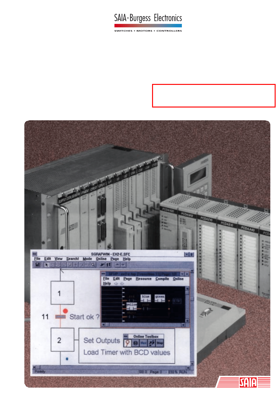
Explanation of format and symbols used in function descriptions:
Function name
[_fupxyz]
Function name
Name of function from the FUPLA
menu (from FBox Selection)
On the left of the FBox are the inputs, e.g.:
Inputs:
−
En
→
Enable
"
−
"
binary input (H/L)
> Set
→
Set
">"
dynamic binary input
= Val
→
Value
"="
numeric input (value)
On the right of the FBox are the outputs, e.g.:
Outputs:
−
Q
→
Output
"
−
"
binary output (H/L)
−
/Q
→
Output inv.
"
−
"
binary output (H/L)
= R
→
Result
"="
numeric output (value)
Field for the base address of the function, normally "O"
or "o" (output) is to be entered, e.g. "o 16"
The dot in the left lower corner indicates that this FBox
has an adjust window. This adjust window can be
opened by double clicking on the FBox. The arrow
symbol must be selected.
FUPLA and KOPLA functions
Overview
26/749 E1
(P-4400-E.DOC)
SAIA AG
Page 4-13
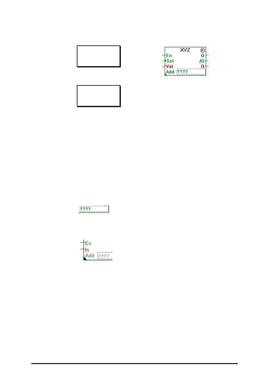
Example for a adjust window: 'Display' - 'D12 Module'.
More complex functions, e.g. communications, contain
an "LED" in the FBox. This remains grey during
programming. In RUN, if everything is okay, the LED
becomes green. If there is an error or is switched to
manual, the LED is red.
[fupabc]
(on the title bar of each function family) shows the file
names of this family, e.g. [sfuptime] for the time related
function family: "sfuptime.def", "sfuptime.hlp",
"sfuptime.idx", "sfuptime.lib".
[_fupxyz]:
Function name within the function family, e.g. [_ondel]
for the delayed switching on in the "sfuptime.xxx"
family.
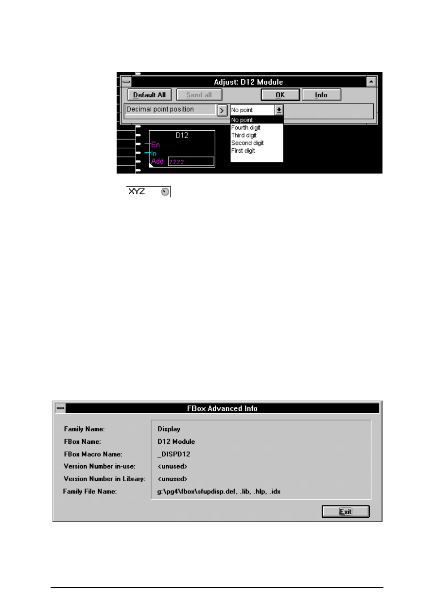
The internal name of the function is shown after
clicking on 'Advanced Info':

FUPLA and KOPLA functions
Binary functions
26/749 E1
(P-4401-E.DOC)
SAIA AG
Page 4-15
4.4.1
Binary functions
[fupbina]
4.4.1.1
And 2-10 inputs
And 2-10 inputs
[_band]
Inputs/Outputs:
−
all
→
binary format.
Outputs the binary AND of its inputs. The output is high only if all in-
puts are high.
Stretchable from 2 to 10 inputs.
E.g.: 2 input And:
In1 | In2 | Out
-----+-----+----
0 | 0 | 0
0 | 1 | 0
1 | 0 | 0
1 | 1 | 1

Binary functions
FUPLA and KOPLA functions
Page 4-16
SAIA AG
(P-4401-E.DOC)
26/749 E1
4.4.1.2
Or 2-10 inputs
Or 2-10 inputs
[_bor]
Inputs/Outputs:
−
all
→
binary format.
Outputs the binary OR of its inputs.
The output is high when at least one of its inputs is high.
Stretchable from 2 to 10 inputs.
E.g.: 2 inputs OR:
In1 | In2 | Out
-----+-----+----
0 | 0 | 0
0 | 1 | 1
1 | 0 | 1
1 | 1 | 1

FUPLA and KOPLA functions
Binary functions
26/749 E1
(P-4401-E.DOC)
SAIA AG
Page 4-17
4.4.1.3
Xor 2-10 inputs
Xor 2-10 inputs
[_bxor]
Inputs/Outputs:
−
all
→
binary format.
Outputs the binary XOR of its inputs.
The output is high when only one of its inputs is high.
Stretchable from 2 to 10 inputs.
E.g.: XOR with 2 inputs:
In1 | In2 | Output
----+-----+-------
0 | 0 |
0
0 | 1 |
1
1 | 0 |
1
1 | 1 |
0
Binary functions
FUPLA and KOPLA functions
Page 4-18
SAIA AG
(P-4401-E.DOC)
26/749 E1
4.4.1.4
Move
Move
[_bmove]
Inputs/Outputs:
−
all
→
binary format.
Outputs its binary input, connects input labels directly to output labels.
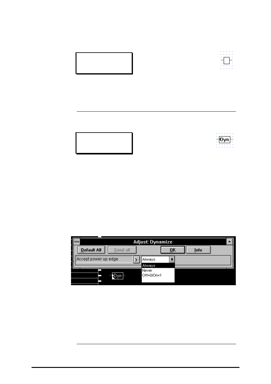
4.4.1.5
Dynamize
Dynamize
[_bdyn2]
Inputs/Outputs:
−
all
→
binary format.
Detects rising edges.
The output is High only when the input has gone from Low to High.
3 options are available to accept edges at power up if the input is already
High.
"Always": Input High is always considered as a rising edge at power up.
"Never": Input High is never considered as a rising edge at power up.
"Off=0/On=1": A rising edge is only considered if the input was Low at
power down and is High at power up.
Warning:
The last option can produce undefined reactions if the
Flags are not reset after a modification of the program!

FUPLA and KOPLA functions
Binary functions
26/749 E1
(P-4401-E.DOC)
SAIA AG
Page 4-19
4.4.1.6
High
High
[_bhigh]
Output:
−
→
binary format.
Outputs a binary high state.
4.4.1.7
Low
Low
[_blow]
Output:
−
all
→
binary format.
Outputs a binary low.
4.4.1.8
Not connected
Not connected
[_bnotcn
]
The "Not Connected" box, terminates unused binary outputs.
Binary functions
FUPLA and KOPLA functions
Page 4-20
SAIA AG
(P-4401-E.DOC)
26/749 E1
4.4.1.9
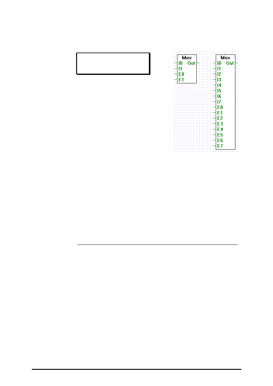
Multiplexer with binary selection
Mux binary selection
[_bmux]
Inputs/Outputs:
−
all
→
binary format.
Transfers an I0..I7 to an output when the corresponding enable signal
E0..E7 is high.
Stretchable from 2 to 8 inputs.
If all enable inputs are low, a low is output.
The enable line E0 has the highest priority and E7 has the lowest.
Therefore if one or more enable lines are actived at the same time, the
input associated with the highest priority enable line will be output.

FUPLA and KOPLA functions
Binary functions
26/749 E1
(P-4401-E.DOC)
SAIA AG
Page 4-21
4.4.1.10
Multiplexer with integer selection
Mux integer selection
[_bmux2]
Inputs:
−
I0:
¦
binary format
−
I7:
= Slc: Selection: integer format
Outputs:
−
Out: binary format
−
Err: binary format
Outputs to "Out" the state of the input "In" selected via the input "Slc"
(e.g. when Slc == 0 outputs the state of I0, when Slc == 5 outputs the
state of I5...).
Stretchable from 2 to 8 inputs "In".
When "Slc" is out of range (i.e. "Slc" < 0 or "Slc" > n), "Out" is set low
and "Err" is set high.
Binary functions
FUPLA and KOPLA functions
Page 4-22
SAIA AG
(P-4401-E.DOC)
26/749 E1
4.4.1.11
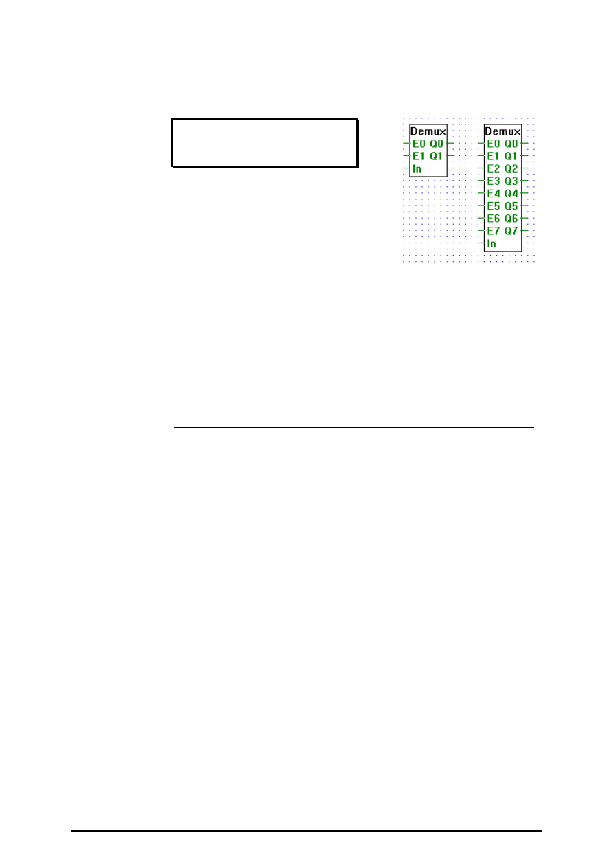
Demultiplexer with binary selection
Demux binary selection
[_bdemux]
Inputs/Outputs:
−
all
→
binary format.
Transfers binary input In to an output (Q0..Q7) when its corresponding
enable line (E0..E7) is high.
Stretchable from 2 to 8 inputs.
When an enable line (E0..E7) is low, its corresponding output (Q0..Q7)
is set low.
FUPLA and KOPLA functions
Binary functions
26/749 E1
(P-4401-E.DOC)
SAIA AG
Page 4-23
4.4.1.12
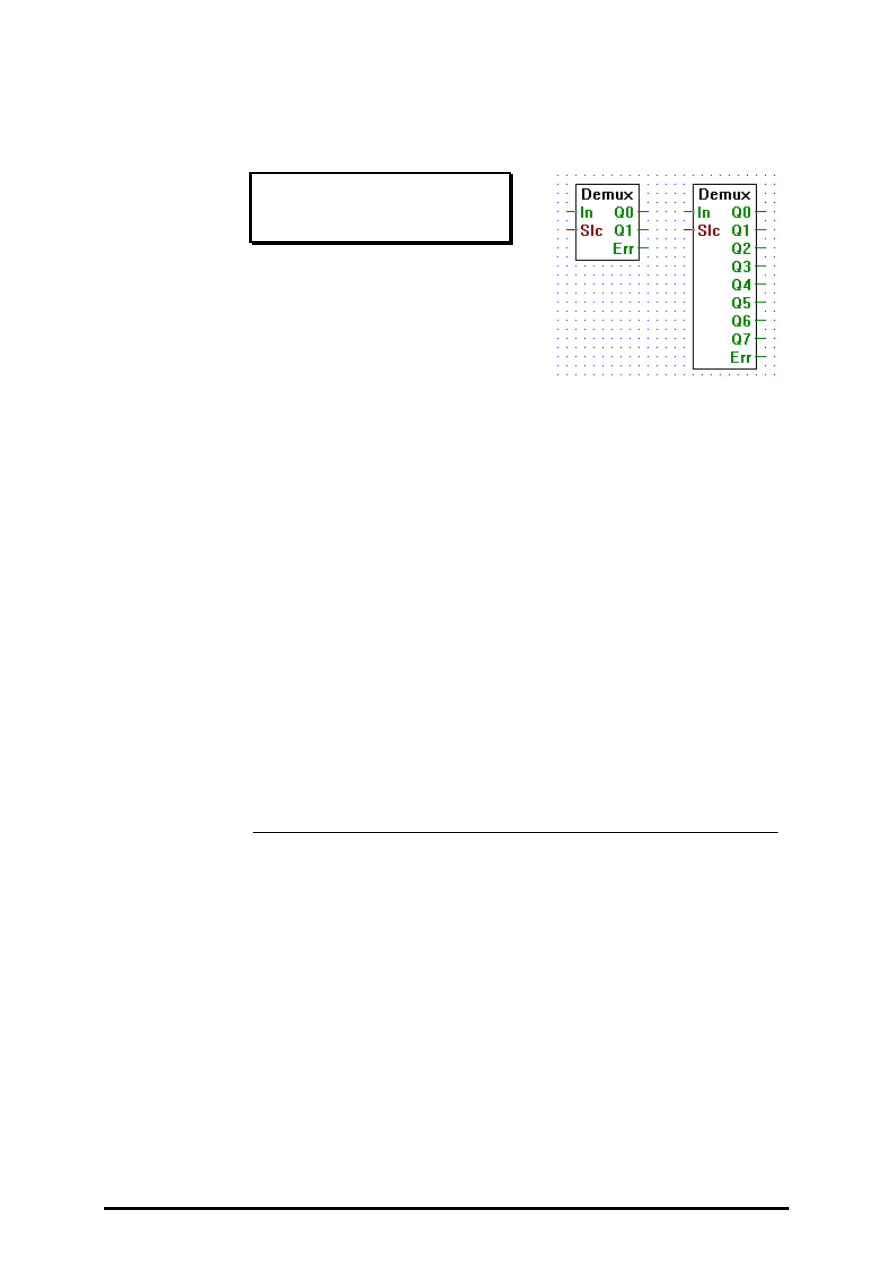
Demultiplexer with integer selection
Demux integer selection
[_bdemux2]
Inputs:
−
In:
binary format
= Slc: Selection: integer format
Outputs:
−
Q0: binary format
¦
−
Q7: binary format
−
Err: binary format
Transfers binary input "In" to a selected output (Q0..Qn). Outputs are
selected via the input "Slc". E.g. when "Slc" == 1 the input "In" is
transfered to "Q1".
When not selected an output is set low.
Stretchable from 2 to 8 outputs.
Err goes high only when "Slc" is out of range, i.e. when "Slc" < 0 or
when "Slc" > n.

Binary functions
FUPLA and KOPLA functions
Page 4-24
SAIA AG
(P-4401-E.DOC)
26/749 E1
4.4.1.13
I/O indirect
I/O.indirect
[_bioind]
Input:
= I/O adresse: integer format
Output:
−
I/O state:
binary format
Outputs the state of I/O number #.
E.g.: if the # input is 5, then the state of I/O 5 is output.
4.4.1.14
Flag indirect
Flag indirect
[_bflgin]
Input:
= Flag adresse:
integer format
Output:
−
Flag state:
binary format
Outputs the state of flag number #.
E.g.: if the # input is 5, then the state of the flag 5 is output.

FUPLA and KOPLA functions
Binary functions
26/749 E1
(P-4401-E.DOC)
SAIA AG
Page 4-25
4.4.1.15
Even, 2-10 inputs
Even 2-10 inputs
[_beven]
Inputs:
−
binary format
Output:
−
binary format
The Output is High if the number of Inputs High is Even. Otherwise, the
Output is Low.
E.g. 3 inputs:
In1 | In2 | In3 | Out
-----+-----+-----+----
0 | 0 | 0 | 1
0 | 0 | 1 | 0
0 | 1 | 0 | 0
0 | 1 | 1 | 1
1 | 0 | 0 | 0
1 | 0 | 1 | 1
1 | 1 | 0 | 1
1 | 1 | 1 | 0

Binary functions
FUPLA and KOPLA functions
Page 4-26
SAIA AG
(P-4401-E.DOC)
26/749 E1
4.4.1.16
Odd, 2-10 inputs
Odd 2-10 inputs
[_bodd]
Inputs:
−
binary format
Output:
−
binary format
The Output is High if the number of Inputs High is Odd. Otherwise, the
Output is Low.
E.g. 3 inputs:
In1 | In2 | In3 | Out
-----+-----+-----+----
0 | 0 | 0 | 0
0 | 0 | 1 | 1
0 | 1 | 0 | 1
0 | 1 | 1 | 0
1 | 0 | 0 | 1
1 | 0 | 1 | 0
1 | 1 | 0 | 0
1 | 1 | 1 | 1

FUPLA and KOPLA functions
Flip-Flops
26/749 E1
(P-4402-E.DOC)
SAIA AG
Page 4-27
4.4.2
Flip-Flops
[sfupflip]
4.4.2.1
Toggle
Toggle
[_flitog]
Inputs/Outputs:
−
all
→
binary format.
Simple toggle function (Flip-Flop).
The state of the output is toggled at each positive edge of the input.
On start up, the output is initialized to Low. If the input is High on start
up, the output is set to High.
Einfache Umschaltfunktion (toggle).
Input __---__-__----__----
Output __-----___------____

Flip-Flops
FUPLA and KOPLA functions
Page 4-28
SAIA AG
(P-4402-E.DOC)
26/749 E1
4.4.2.2
Type D
Type D
[_flid]
Inputs/Outputs:
−
all
→
binary format.
D type flip-flop with a rising edge triggered clk input.
The state of the input D is stored when the clk input goes from the low to
high.
The output Q is always the last stored state of input D.
D _____------_-__--___
Clk __--__--__--__--__--
Q ______--------______

FUPLA and KOPLA functions
Flip-Flops
26/749 E1
(P-4402-E.DOC)
SAIA AG
Page 4-29
4.4.2.3
Type RS dynamized
Type RS dynamized
[_flirs]
Inputs/Outputs:
−
all
→
binary format.
RS flip-flop, with priority on the R input. Both R and S are rising edge
triggered.
When input R goes from low to high, output Q is set low.
When input S goes from low to high, output Q is set high.
When both inputs R and S go from low to high at the same time, output Q
is set low.
In all the other cases the output is unchanged.
R ___--________---____--___
S _______---_____---__---__
Q _______------__-----_____
R | S | Q
---+---+---
X | X | Unchanged
X |_/-| 1
_/-| X | 0
_/-|_/-| 0
_/-
=
rising edge.
X
=
any state.

Flip-Flops
FUPLA and KOPLA functions
Page 4-30
SAIA AG
(P-4402-E.DOC)
26/749 E1
4.4.2.4
Type SR dynamized
Type SR dynamized
[_flisr]
Inputs/Outputs:
−
all
→
binary format.
RS flip-flop, with priority on the S input. Both R and S are rising edge
triggered.
When input R goes from low to high, output Q is set low.
When input S goes from low to high, output Q is set high.
When both inputs R and S go from low to high at the same time, output Q
is set high.
In all the other cases the output is unchanged.
R _______---_____---__--___
S ___--________---____---__
Q ___----______--_____-----
R | S | Q
---+---+---
X | X | Unchanged
X |_/-| 1
_/-| X | 0
_/-|_/-| 1
_/-
=
rising edge.
X
=
any state.

FUPLA and KOPLA functions
Flip-Flops
26/749 E1
(P-4402-E.DOC)
SAIA AG
Page 4-31
4.4.2.5
Type JK
Type JK
[_flijk]
Inputs/Outputs:
−
all
→
binary format.
Clocked JK flip-flop.
The J and K inputs are read only when a rising edge is detected on the Clk
input. When no rising edge is detected, the output Q is unchanged.
When a rising edge is detected on the Clk input:
•
and J is high, Q is reset low,
•
and K is high, Q is set high,
•
and J and K are high, Q is toggled,
•
and J and K are low, Q is unchanged.
Clk __--__--__--__--__--_
J _______-_-------_---_
K ____----_____--_----_
Q ______----____----___
Clk | J | K | Q(t)
----+---+---+---
X | X | X | Q(t-1)
_/- | 0 | 0 | Q(t-1)
_/- | 0 | 1 | 1
_/- | 1 | 0 | 0
_/- | 1 | 1 | /Q(t-1) (toggle)
_/-
=
rising edge.
X
=
any state.

Flip-Flops
FUPLA and KOPLA functions
Page 4-32
SAIA AG
(P-4402-E.DOC)
26/749 E1
4.4.2.6
Type RS clocked
Type RS clocked
[_flirsclk]
Inputs/Outputs:
−
all
→
binary format.
Clocked RS flip-flop, with priority on the R input.
Inputs R and S are read when a rising edge is detected on input Clk.
When no rising edge is detected, output Q is unchanged.
When a rising edge is detected at input Clk:
•
and R is high, Q is reset low,
•
and S is high, Q is set high,
•
and R and S are high, Q is reset low,
•
and R and S are low, Q is unchanged.
Clk __--__--__--__--__--_
R _______-_---_____---_
S ____--------_---_____
Q ______----____----___
Clk | R | S | Q
----+---+---+---
X | X | X | Unchanged
_/- | 0 | 0 | Unchanged
_/- | 0 | 1 | 1
_/- | 1 | 0 | 0
_/- | 1 | 1 | 0
_/-
=
rising edge.
X
=
any state.

FUPLA and KOPLA functions
Flip-Flops
26/749 E1
(P-4402-E.DOC)
SAIA AG
Page 4-33
4.4.2.7
Type SR clocked
Type SR clocked
[_flisrclk]
Inputs/Outputs:
−
all
→
binary format.
Clocked RS flip-flop, with priority on the S input.
Inputs R and S are read when a rising edge is detected on input Clk.
When no rising edge is detected, output Q is unchanged.
When a rising edge is detected at input Clk:
•
and R is high, Q is reset low,
•
and S is high, Q is set high,
•
and R and S are high, Q is set high,
•
and R and S are low, Q is unchanged.
Clk __--__--__--__--_
R ____--------_---_
S _--____-_---_____
Q __----____----___
Clk | R | S | Q
----+---+---+---
X | X | X | Unchanged
_/- | 0 | 0 | Unchanged
_/- | 0 | 1 | 1
_/- | 1 | 0 | 0
_/- | 1 | 1 | 1
_/-
=
rising edge.
X
=
any state.

Flip-Flops
FUPLA and KOPLA functions
Page 4-34
SAIA AG
(P-4402-E.DOC)
26/749 E1
4.4.2.8
Type RS
Type RS
[_flirsndyn]
Inputs/Outputs:
−
all
→
binary format.
RS flip-flop, with priority on the R input.
When input R is high, output Q is set low.
When input S is high and input R is low, output Q is set high.
When both inputs R and S are high, output Q is set low.
In all the other cases the output is unchanged.
R ___--________---____--___
S _______---_____---___---_
Q _______------___----__---
R | S | Q
---+---+---
0 | 0 | Unchanged
1 | X | 0
0 | 1 | 1
X
=
any state.

FUPLA and KOPLA functions
Flip-Flops
26/749 E1
(P-4402-E.DOC)
SAIA AG
Page 4-35
4.4.2.9
Type SR
Type SR
[_flisrndyn]
Inputs/Outputs:
−
all
→
binary format.
RS flip-flop, with priority on the S input.
When input R is high and input S is low, output Q is set low.
When input S is high, output Q is set high.
When both inputs R and S are high, output Q is set high.
In all the other cases the output is unchanged.
R _______---_____---___---__
S ___--________---____---___
Q ___----______---____---___
R | S | Q
---+---+---
0 | 0 | Unchanged
X | 1 | 1
1 | 0 | 0
X
=
any state.

FUPLA and KOPLA functions
Counters
26/749 E1
(P-4403-E.DOC)
SAIA AG
Page 4-37
4.4.3
Counters
[sfupcoun]
4.4.3.1
Up count with preset
Up with preset
[_uppr2]
Inputs:
−
Set:
binary format
> Up:
binary format
= IC
Initial Count: integer format
Outputs:
−
Q:
pos/neg
binary format
=
Cnt: Count
integer
format
−
Err: Error
binary format
Increments a counter each time a rising edge is detected on input Up. The
count is output at Cnt.
The Set input loads the counter with value IC.
If the counter is > 0, the output Q is High and if it is <= 0, the output Q is
Low.
If the counter overflows, output Err is set high.

Counters
FUPLA and KOPLA functions
Page 4-38
SAIA AG
(P-4403-E.DOC)
26/749 E1
4.4.3.2
Down count with preset
Down with preset
[_dwnpr2]
Inputs:
−
Set:
binary format
> Dwn: Down:
binary format
= IC: Initial Count: integer format
Outputs:
−
Q:
pos/neg
binary format
= Cnt: Count
integer format
−
Err: Error
binary format
Decrements a counter each time a rising edge is detected on input Dwn.
The count is output at Cnt.
The Set input loads the counter with value IC.
If the counter is > 0, the output Q is High and if it is <= 0, the output Q is
Low.
If the counter underflows, output Err is set high.

FUPLA and KOPLA functions
Counters
26/749 E1
(P-4403-E.DOC)
SAIA AG
Page 4-39
4.4.3.3
Up count
Up
[_up2]
Inputs:
−
Clr: Clear
binary format
> Up:
binary format
Outputs:
−
Q:
pos/neg
binary format
= Cnt: Count
integer format
−
Err: Error
binary format
Increments a counter each time a rising edge is detected on input Up. The
count is output at Cnt.
The Clr input clears the counter.
If the counter is > 0, the output Q is High and if it is <= 0, the output Q is
Low.
If the counter overflows, output Err is set high.

Counters
FUPLA and KOPLA functions
Page 4-40
SAIA AG
(P-4403-E.DOC)
26/749 E1
4.4.3.4
Up/down count with preset
Up/down with preset
[_updnpr2]
Inputs:
−
Set:
binary format
> Up:
binary format
> Dwn:
binary format
= IC: Initial Count: integer format
Outputs:
−
Q:
pos/neg
binary format
= Cnt: Count
integer format
−
Err: Error
binary format
Increments or decrements a counter each time a rising edge is detected on
the corresponding input Up or Dwn. The count is output at Cnt.
The Set input loads the counter with value IC.
If the counter is > 0, the output Q is High and if it is <= 0, the output Q is
Low.
If the counter overflows or underflows, output Err is set high.
FUPLA and KOPLA functions
Counters
26/749 E1
(P-4403-E.DOC)
SAIA AG
Page 4-41
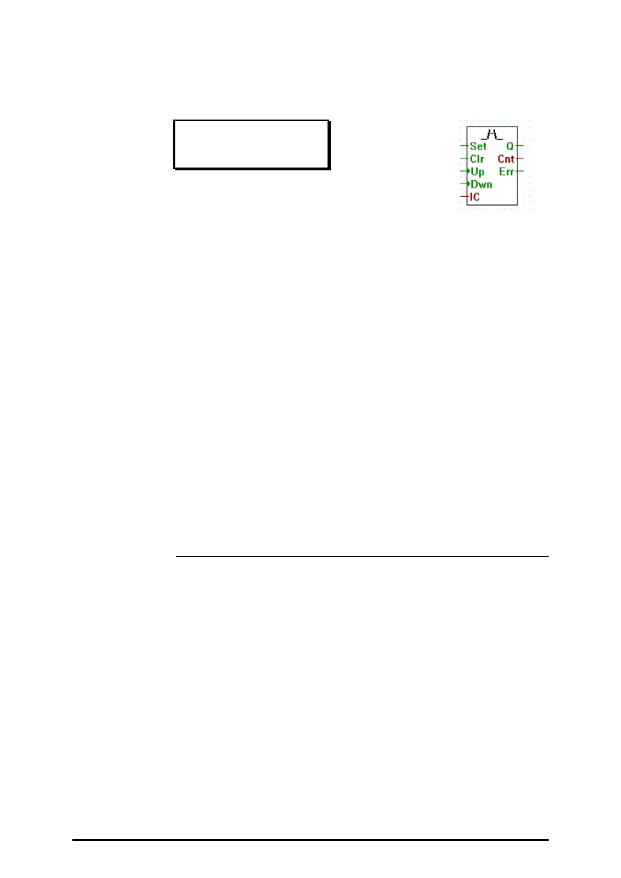
4.4.3.5
Up/down count with preset and clear
Up/down preset and clear
[_updnsc]
Inputs:
−
Set:
binary format
−
Clr
binary format
> Up:
binary format
> Dwn:
binary format
= IC: Initial Count: integer format
Outputs:
−
Q:
pos/neg
binary format
= Cnt: Count
integer format
−
Err: Error
binary format
Increments or decrements a counter each time a rising edge is detected on
the corresponding input Up or Dwn. The count is output at Cnt.
The Set input loads the counter with value IC.
The Clr input clears the counter.
If the counter is > 0, the output Q is High and if it is <= 0, the output Q is
Low.
If the counter overflows or underflows, output Err is set high.

FUPLA and KOPLA functions
Time related functions
26/749 E1
(P-4404-E.DOC)
SAIA AG
Page 4-43
4.4.4
Time related functions
[sfuptime]
4.4.4.1
On delay
On delay
[_ondel]
Inputs: > In:
Activate
binary format
= TV: Timer Value: integer format
Outputs:
−
Q
Output
binary format
= t:
actual value
integer format
On-delay timer.
Q is set high at TV timer units after In was set high. When In goes low, Q
is immediately set low.
If In goes high for a period smaller than TV, then Q is unaffected. t indi-
cates the value of the internal timer.
E.g.
In ___-------___--__------__
Q _______---___________--__
<TV> <TV>

Time related functions
FUPLA and KOPLA functions
Page 4-44
SAIA AG
(P-4404-E.DOC)
26/749 E1
4.4.4.2
Store delay
Store delay
[_stodel]
Inputs: > In:
Activate
binary format
= TV: Timer Value: integer format
−
R:
Reset
binary format
Outputs:
−
Q
Output
binary format
= t:
actual value
integer format
Store on-delay timer.
When In goes high, Q is set high at TV timer units later.
Once Q is set high it goes low only when R (reset) is activated (set high).
When R is activated, Q is held low no matter the state of In.
If In goes to high for a period smaller than TV then Q is unaffected.
t indicates the value of the internal timer.
E.g.
In ___------____--__------__--------
R __________--_______________------
Q _______---___________--------____
<TV> <TV>

FUPLA and KOPLA functions
Time related functions
26/749 E1
(P-4404-E.DOC)
SAIA AG
Page 4-45
4.4.4.3
Exclusive pulse
Exclusive pulse
[_xpulse]
Inputs: > In:
Activate
binary format
= TV: Timer Value: integer format
Outputs:
−
Q
Output
binary format
= t:
actual value
integer format
Extended pulse timer, generates a pulse of duration TV when it detects a
rising edge on the input.
t indicates the value of the internal timer.
E.g.
In__------__--____
Q __----____----__
<TV> <TV>

Time related functions
FUPLA and KOPLA functions
Page 4-46
SAIA AG
(P-4404-E.DOC)
26/749 E1
4.4.4.4
Off delay
Off delay
[_offdel]
Inputs: > In:
Activate
binary format
= TV: Timer Value: integer format
Outputs:
−
Q
Output
binary format
= t:
actual value
integer format
Off-delay timer.
When In goes high, Q is immediately set high.
Q is set low at TV timer units after In was set low.
If In goes high-low-high for a period smaller than TV, then Q is unaf-
fected.
t indicates the value of the internal timer.
E.g.
In ___---_______--_---_______
Q ___-------___----------___
<TV> <TV>

FUPLA and KOPLA functions
Time related functions
26/749 E1
(P-4404-E.DOC)
SAIA AG
Page 4-47
4.4.4.5
On/off delay
On/off delay
[_onoffd2]
Inputs: > In:
Activate
binary format
= T0: Timer Value 0
integer format
= T1: Timer Value 1
integer format
Outputs:
−
Q
Output
binary format
−
D
Delay active/inactive binary format
On-off-delay timer.
Output Q is set high at T1 timer units after input In was set high.
Output Q is set low at T0 timer units after input In was set low.
Output "D" = H: delay active,
Output "D" = L: delay inactive.
E.g.
In ___-------_____________
Q _______-------------___
<T1>
<---T0--->
In __-_------_-___________
Q ________--------------_
<T1> <---T0--->

Time related functions
FUPLA and KOPLA functions
Page 4-48
SAIA AG
(P-4404-E.DOC)
26/749 E1
4.4.4.6
Off delay with reset
Off delay with reset
[_offdelr]
Inputs: > In:
Activate
binary format
−
R:
Reset
binary format
= TV: Timer Value: integer format
Outputs:
−
Q
Output
binary format
= t:
actual value
integer format
Off-delay timer with reset.
When In goes high, Q is immediately set high.
Q is set low at TV timer units after In was set low.
If R is high the timer is cleared and Q is low.
If In goes high-low-high for a period smaller than TV, then Q is unaf-
fected.
t indicates the value of the internal timer.
E.g.
In ___---_______--___________
R _________________------___
Q ___-------___----_________
<TV> <TV>

FUPLA and KOPLA functions
Time related functions
26/749 E1
(P-4404-E.DOC)
SAIA AG
Page 4-49
4.4.4.7
Pulse
Pulse
[_pulse]
Inputs: > In:
Activate
binary format
= TV: Timer Value: integer format
Outputs:
−
Q
Output
binary format
= t:
actual value
integer format
Pulse timer, generates a pulse of duration TV when it detects a rising edge
on the input.
If the input goes low before time TV, the pulse will be truncated.
t indicates the value of the internal timer.
E.g.
In __--------__--____
Q __----______--____
<TV> <TV>

Time related functions
FUPLA and KOPLA functions
Page 4-50
SAIA AG
(P-4404-E.DOC)
26/749 E1
4.4.4.8
Chronometer
Chronometer
[_chrono2]
Inputs:
−
En: Enable
binary format
−
Clr: Clear :
binary format
Outputs:= t:
actual value
integer format
Calculates time intervals. The Clr input resets the timer. The En input
starts the timer when high and stops it when low. The timer value is out-
put at t.

FUPLA and KOPLA functions
Time related functions
26/749 E1
(P-4404-E.DOC)
SAIA AG
Page 4-51
4.4.4.9
Time (Hardware clock)
Time
[_time]
Outputs:= HMS:
Hours, Minutes, Seconds:
integer fornat
= Day:
Day and Date
integer format
Reads the contents of the internal hardware clock into 2 integer outputs.
The outputs are set as follows:
HMS
Day
Content Digit nb.
0
9-6
Hours
5-4
Minutes
3-2
Seconds
1-0
Content Digit nb.
0
9
Week
8-7
Week Day
6
Year
5-4
Month
3-2
Day
1-0
See also the description of the PCD's RTIME instruction.
Time related functions
FUPLA and KOPLA functions
Page 4-52
SAIA AG
(P-4404-E.DOC)
26/749 E1
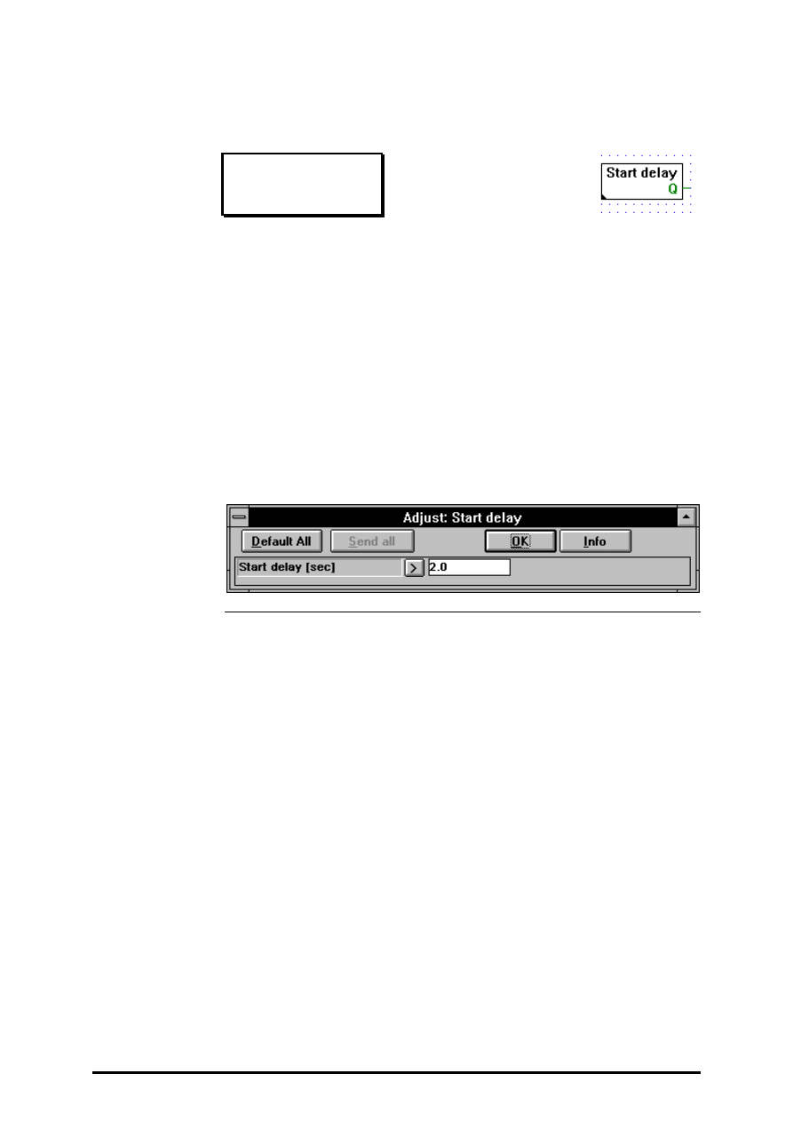
4.4.4.10
Start delay
Start delay
[_stdel]
Output:
−
Q:
Ready for start PCD program:
binary format
Start-delay timer.
Q is set low from the PCD's start up until the delay time is reached. Then
it is kept high.
E.g.
PCD Start up _____----------------
Q ______________-------
< Delay >
FUPLA and KOPLA functions
Blinker
26/749 E1
(P-4405-E.DOC)
SAIA AG
Page 4-53
4.4.5
Blinker
[sfupblin]
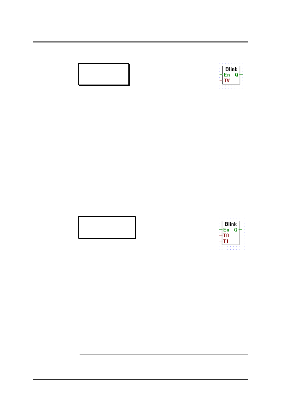
4.4.5.1
Blink delay T
Blink delay T
[_blink1]
Inputs:
−
En: Enable
binary format
= TV: Time Value
integer format
Output:
−
Q:
Blinker output
integer format
Blinks output Q with period TV while enable input En is high.
When En is low, Q is set low.
En ____------------------___
Q ____----____----____--___
<TV> <TV>
4.4.5.2
Blink delay T0/T1
Blink delay T0/T1
[_blink2]
Inputs:
−
En: Enable
binary format
= T0
Time Value 0
integer format
= T1
Time Value 1
integer format
Output:
−
Q:
Blinker output
integer format
Blinks output Q with period T1 in the high state and a period T0 in the
low state while enable input En is high.
When En is low, Q is set low.
En ____----------------------___
Q ____----______----______--___
<T1><-T0-><T1><-T0-><T1>

Blinker
FUPLA and KOPLA functions
Page 4-54
SAIA AG
(P-4405-E.DOC)
26/749 E1
4.4.5.3
Sample
Sample
[_blinksamp]
Inputs:
−
En: Enable
binary format
= Tv
Time value
integer format
Output:
−
Q:
Sample output
integer format
When the signal enable En is high, Sample output Q with period Tv, in the
high state during one program cycle, and output it in low state during the
rest of the period.
When En is low, Q is set low, and the timer is reset to 0.
En ____------------------___
Q ____-___-___-___-___-____
<Tv> > < Program Cycle
FUPLA and KOPLA functions
Integer arithmetic
26/749 E1
(P-4406-E.DOC)
SAIA AG
Page 4-55
4.4.6
Integer arithmetic
[sfupinte]
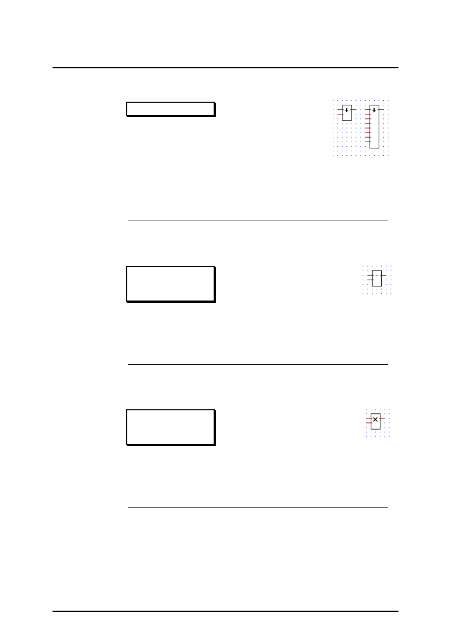
4.4.6.1
Add
Add
[_iadd]
Inputs/Outputs: = all
→
integer format.
Adds the input values and transfers the result to the output.
Stretchable from 2 to 8 inputs.
4.4.6.2
Subtract
Subtract
[_isub]
Inputs/Outputs: = all
→
integer format.
Outputs The result of the upper input minus the lower.
4.4.6.3
Multiply
Multiply
[_imul]
Inputs/Outputs: = all
→
integer format.
Outputs the result of the multiplication of its two inputs.
Integer arithmetic
FUPLA and KOPLA functions
Page 4-56
SAIA AG
(P-4406-E.DOC)
26/749 E1
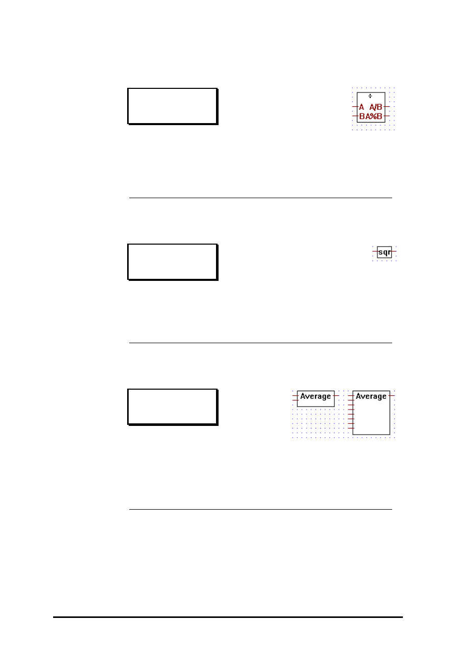
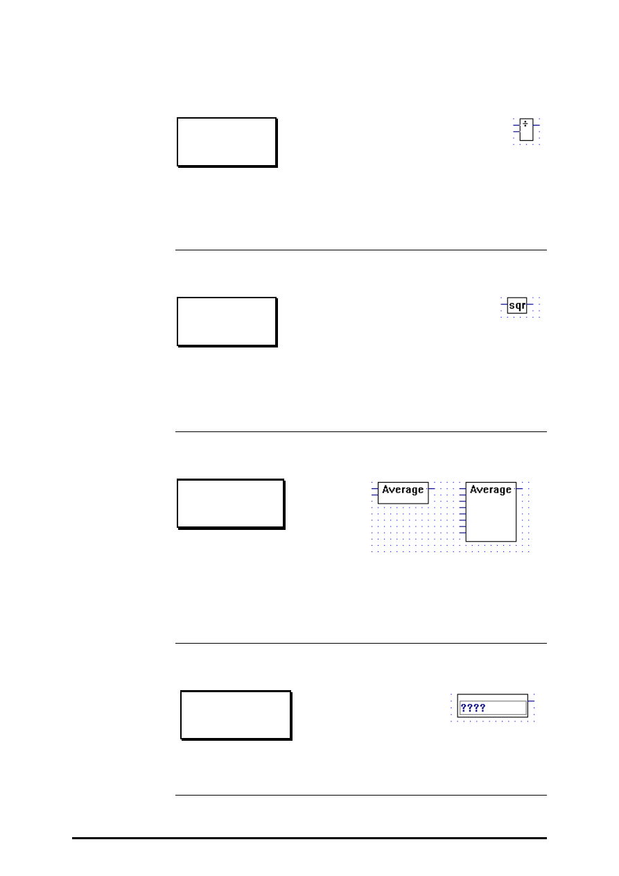
4.4.6.4
Divide
Divide
[_idiv]
Inputs/Outputs: = all
→
integer format.
Outputs A/B is set to the integer result of input A divided by input B.
The remainder (modulo) is output to A%B.
4.4.6.5
Square root
Square root
[_isqr]
Inputs/Outputs: = all
→
integer format.
Outputs the integer square root of its input.
4.4.6.6
Average
Average
[_iaverage]
Inputs/Outputs: = all
→
integer format.
Ouputs the average of its input values.
Stretchable from 2 to 8 inputs.
FUPLA and KOPLA functions
Integer arithmetic
26/749 E1
(P-4406-E.DOC)
SAIA AG
Page 4-57
4.4.6.7
Constant
Constant
[_iconst]
Inputs/Outputs: = all
→
integer format.
Outputs the integer constant written in the entry-field.
4.4.6.8
Absolute
Absolute
[_iabs]
Outputs the absolute value of the input.
4.4.6.9
Bitwise and
Bitwise and
[_iand]
Inputs/Outputs: = all
→
integer format.
Outputs the logical AND of the first input with the second input.
4.4.6.10
Bitwise or
Bitwise or
[_ior]
Inputs/Outputs: = all
→
integer format.
Outputs the logical OR of the first input with the second input.
Integer arithmetic
FUPLA and KOPLA functions
Page 4-58
SAIA AG
(P-4406-E.DOC)
26/749 E1
4.4.6.11
Bitwise exclusive or
Bitwise exclusive or
[_ixor]
Inputs/Outputs: = all
→
integer format.
Outputs the logical XOR of the first input with the second input.
4.4.6.12
Bitwise invert
Bitwise invert
[_inot]
Inputs/Outputs: = all
→
integer format.
Outputs the invertion (1's complement) of the input.
4.4.6.13
Is equal to
Is equal to
[_icmpeq]
Inputs: = all
→
integer format
Output:
−
binary format
Outputs binary high when both inputs are equal, else outputs
binary low.
FUPLA and KOPLA functions
Integer arithmetic
26/749 E1
(P-4406-E.DOC)
SAIA AG
Page 4-59
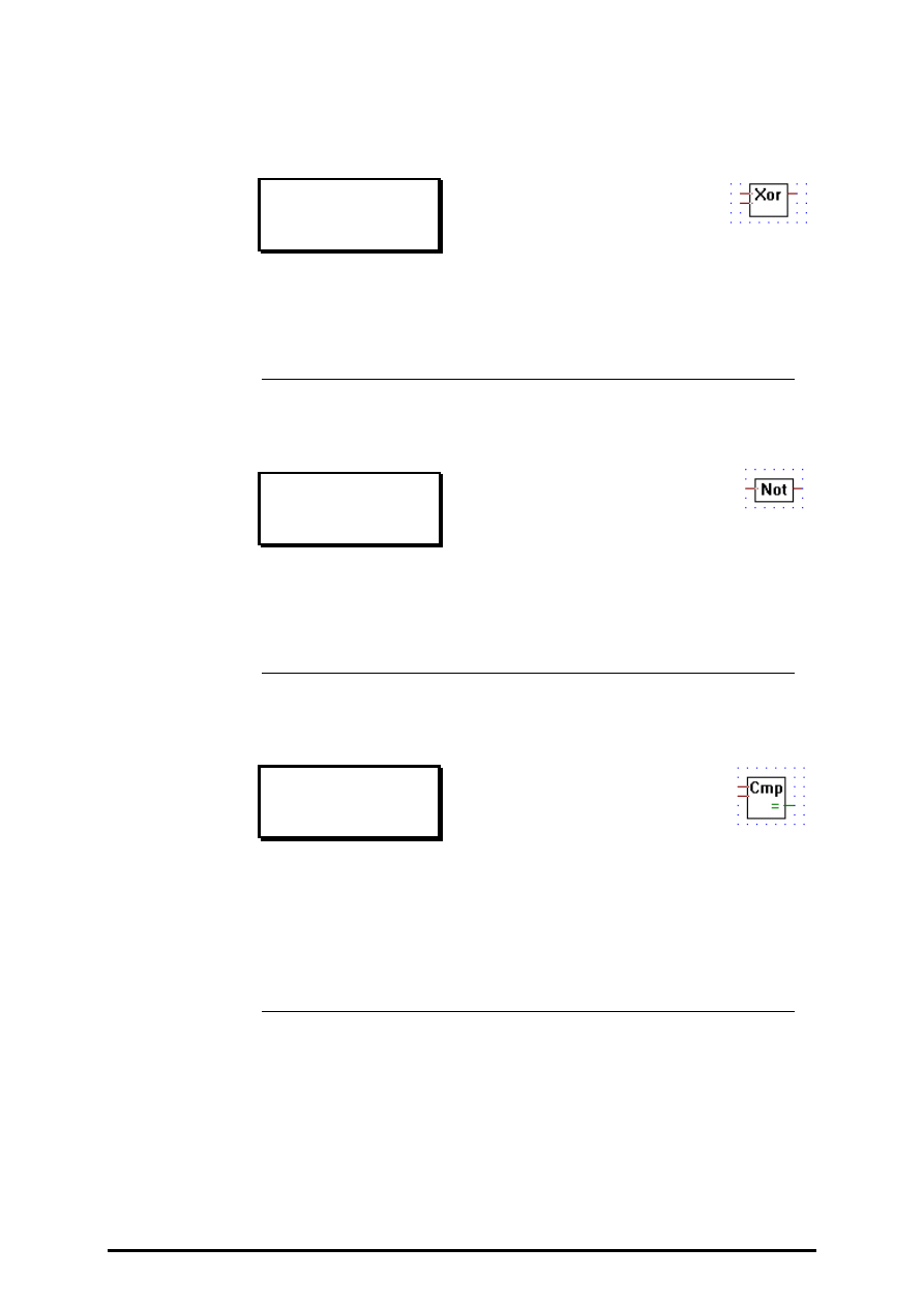
4.4.6.14
Is greater or equal to
Is greater or equal to
[_icmpge]
Inputs: = all
→
integer format
Output:
−
binary format
Outputs binary high when the upper input is greater or equal to the
lower input, else outputs binary low.
4.4.6.15
Is greater than
Is greater than
[_icmpgt]
Inputs: = all
→
integer format
Output:
−
binary format
Outputs binary high when the upper input is greater than the lower in-
put, else outputs binary low.
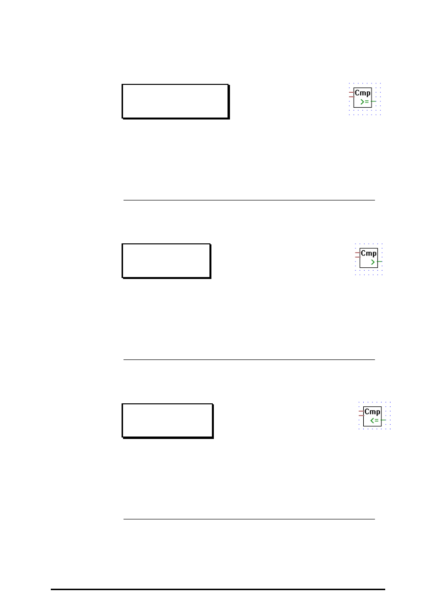
4.4.6.16
Is smaller or equal to
Is smaller or equal to
[_icmpse]
Inputs: = all
→
integer format
Output:
−
binary format
Outputs binary high when the upper input is less than or equal to the
lower input, else outputs binary low.
Integer arithmetic
FUPLA and KOPLA functions
Page 4-60
SAIA AG
(P-4406-E.DOC)
26/749 E1
4.4.6.17
Is smaller than
Is smaller than
[_icmpst]
Inputs: = all
→
integer format
Output:
−
binary format
Outputs binary high when the upper input is less than the lower input,
else outputs binary low.
4.4.6.18
Is zero
Is zero
[_iiszero]
Inputs: = all
→
integer format
Output:
−
binary format
Outputs high when its integer input is zero, else output low.
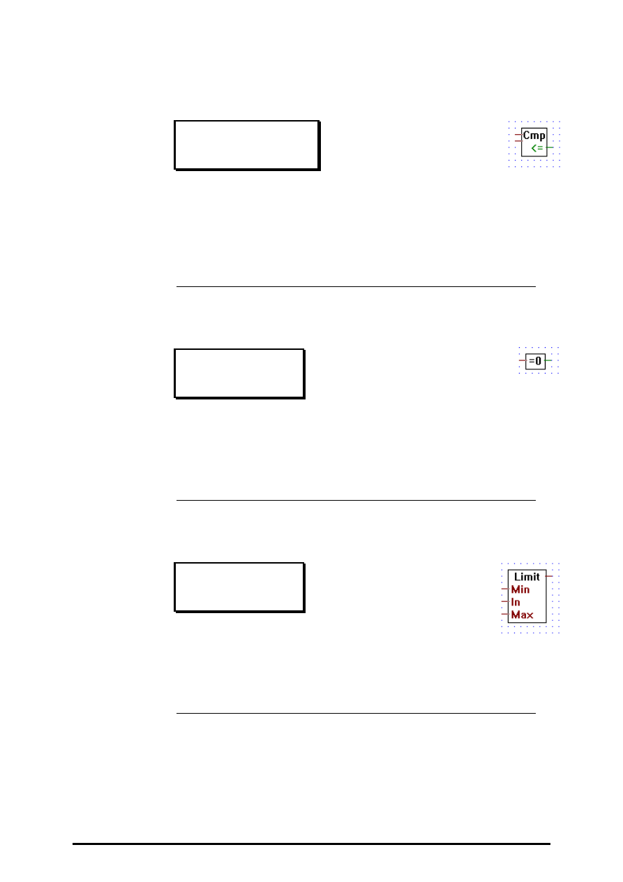
4.4.6.19
Limit
Limit
[_ilimit]
Inputs/Outputs: = all
→
integer format.
Outputs the input value In. The output value is limited between Max
and Min.

FUPLA and KOPLA functions
Integer arithmetic
26/749 E1
(P-4406-E.DOC)
SAIA AG
Page 4-61
4.4.6.20
Maximum
Maximum
[_imax]
Inputs/Outputs: = all
→
integer format.
Outputs the largest of its input value.
Stretchable from 2 to 8 inputs.
4.4.6.21
Minimum
Minimum
[_imin]
Inputs/Outputs: = all
→
integer format.
Outputs the smallest input value.
Stretchable from 2 to 8 inputs.
4.4.6.22
Move
Move
[_imove]
Inputs/Outputs: = all
→
integer format.
Outputs its integer input, used to connect an input label directly to an
output label.
Integer arithmetic
FUPLA and KOPLA functions
Page 4-62
SAIA AG
(P-4406-E.DOC)
26/749 E1
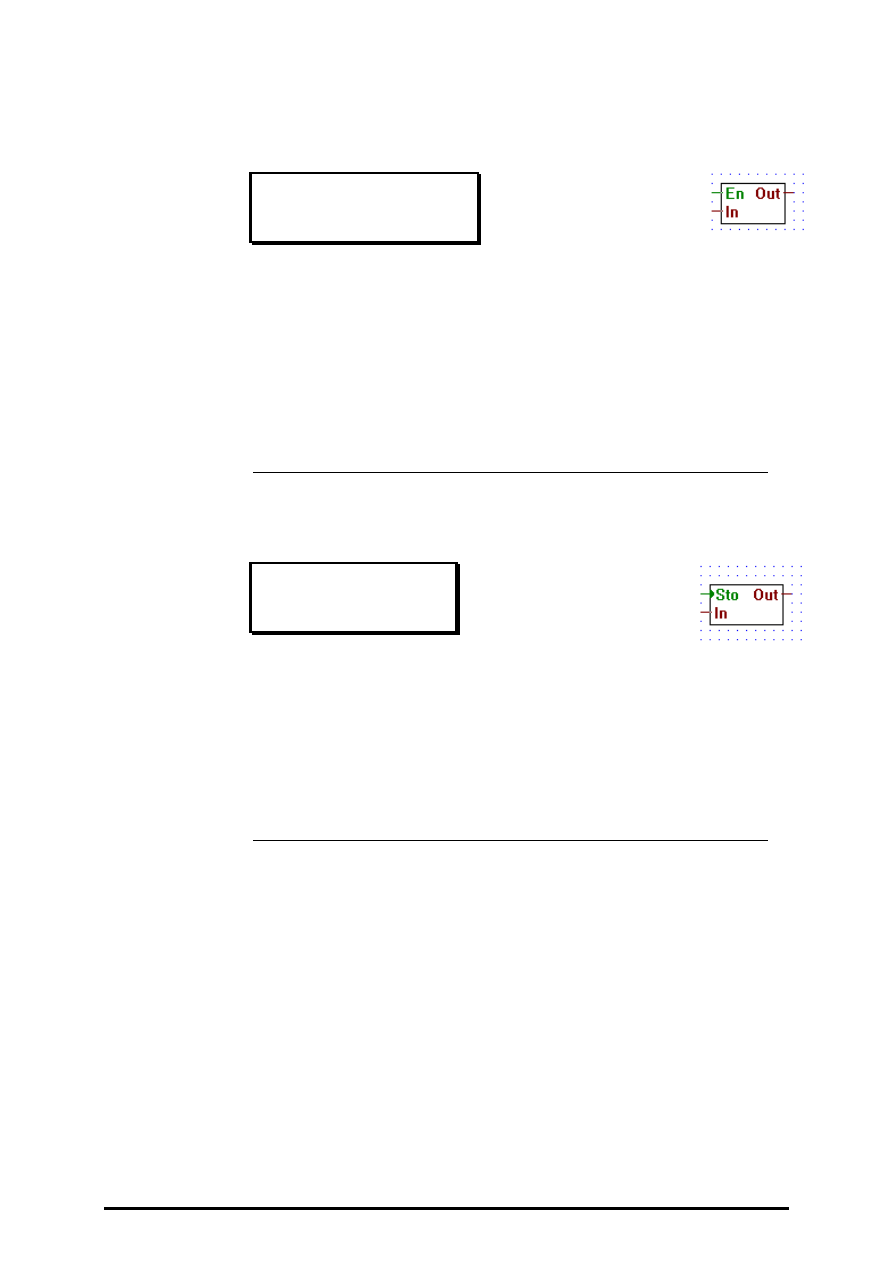
4.4.6.23
Move when enabled
Move when enabled
[_imovee]
Inputs:
−
En: Enable (binary format)
= In:
Input (integer format)
Output: = Out Output (integer format)
Outputs its input when the enable line is high.
If "En" = L, the output value is zero.
4.4.6.24
Move and store
Move and store
[_imoves]
Inputs: > Sto: Store (Binary format)
= In:
Input (integer format)
Output: = Out: Output (integer format)
Stores its input in an internal register when Sto goes from low to high.
Always outputs the contents of its internal register.
FUPLA and KOPLA functions
Integer arithmetic
26/749 E1
(P-4406-E.DOC)
SAIA AG
Page 4-63
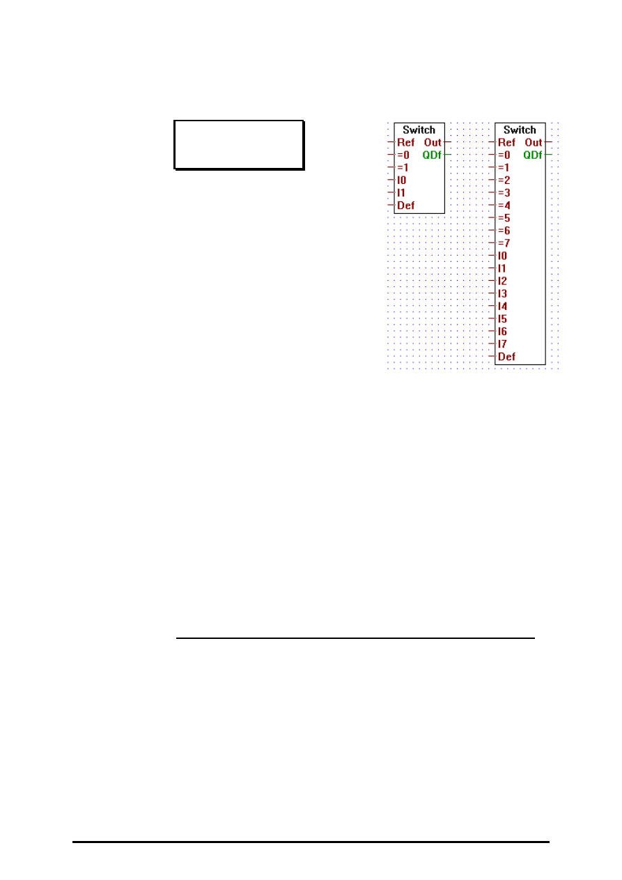
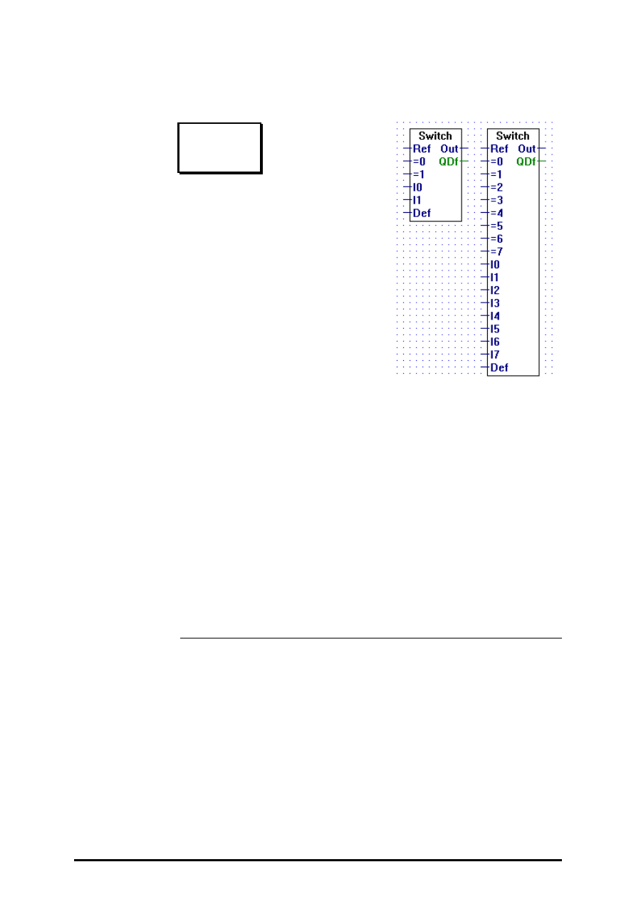
4.4.6.25
Switch
Switch
[_iswitch]
Inputs: = all:
integer format
Outputs:= Out: integer format
−
QDf binary format
When the input "Ref" is equal to one of its input "=n" it transfers the cor-
responding input "In" to the output.
When there are no input "=n" equal to "Ref" then the input "Def" is
output to "Out", and the output QDf is set high.
Stretchable from I1 to I7.
Input I0 as higher priority than I7. When more than one input "=n"
equals the input "Ref", than only the input with the highest priority is
transfered.
Integer arithmetic
FUPLA and KOPLA functions
Page 4-64
SAIA AG
(P-4406-E.DOC)
26/749 E1
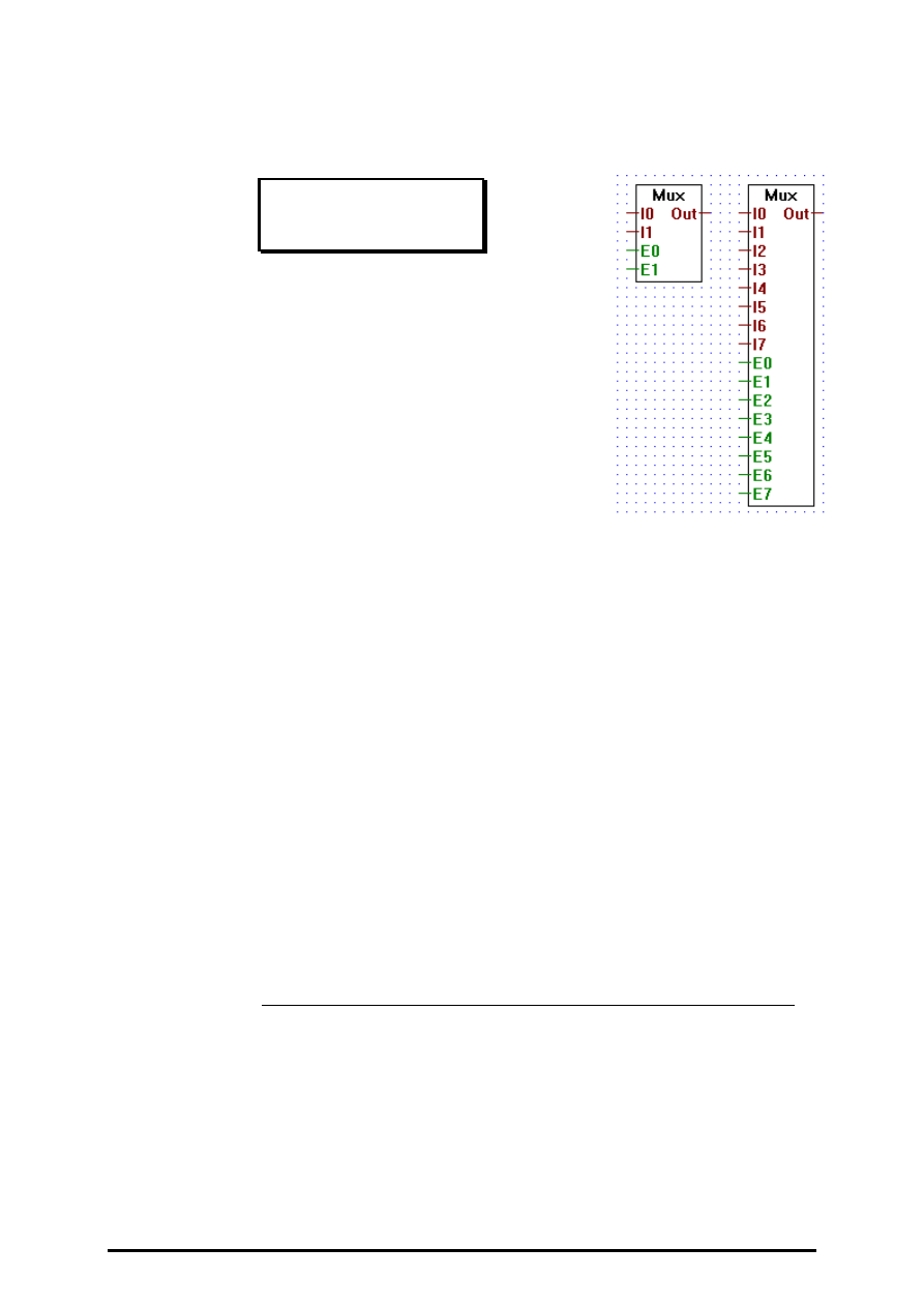
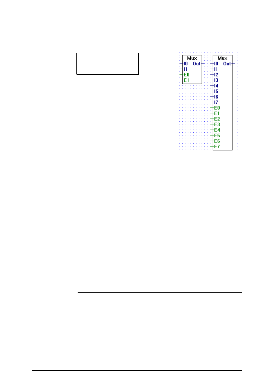
4.4.6.26
Multiplexer with binary selection
Mux bin selection
[_imux]
Inputs: = I0:
¦
integer format
= I7:
−
E0:
¦
binary format
−
E7:
Output: = Out: integer format
Outputs the state of input "In" when its corresponding enable input
"En" is high.
Stretchable from 2 to 8 inputs "In".
If all enable inputs "En" are low, then 0 is output.
The enable line E0 has the highest priority and E7 has the lowest.
Therefore if 2 or more enable lines are set actived at the same time, the
input associated with the highest priority enable line will be
output.
FUPLA and KOPLA functions
Integer arithmetic
26/749 E1
(P-4406-E.DOC)
SAIA AG
Page 4-65
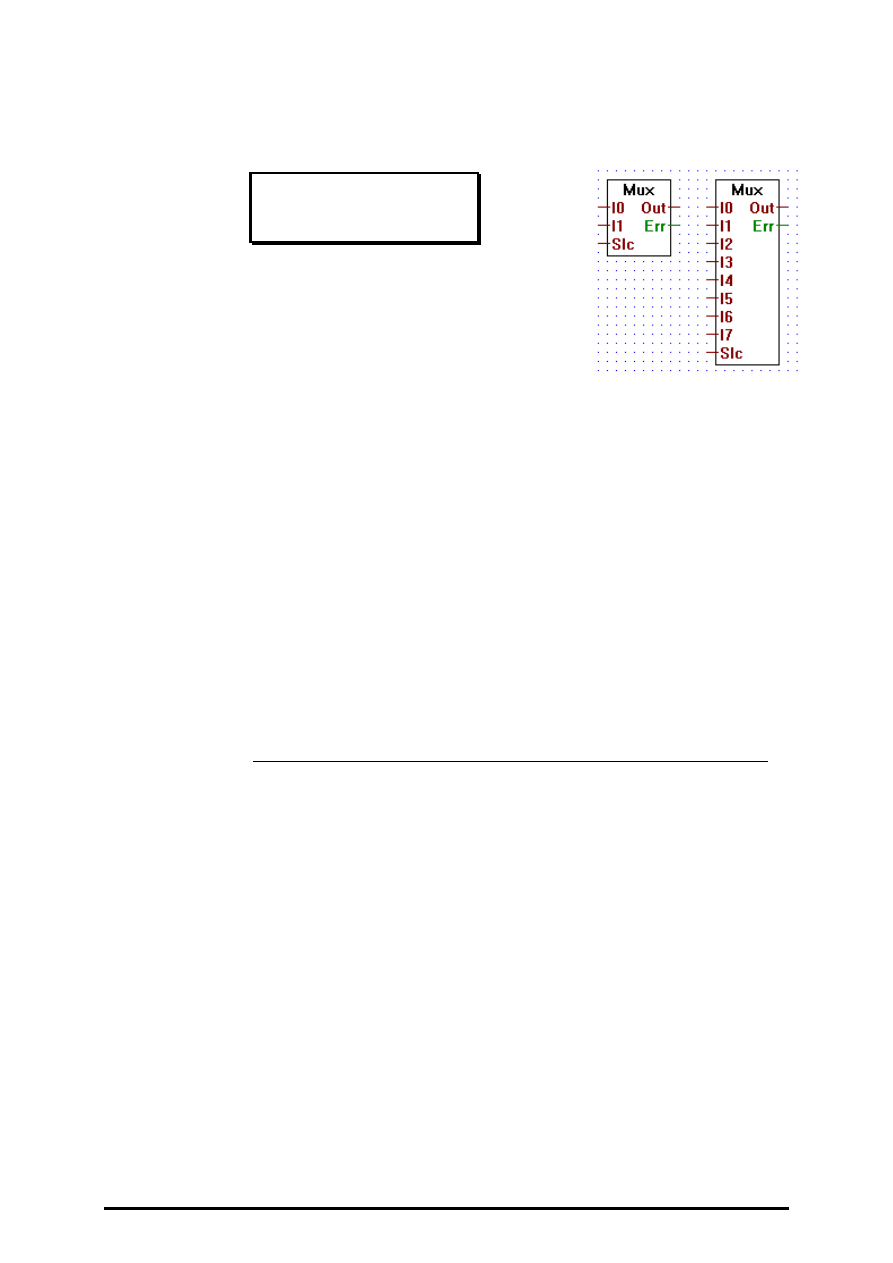
4.4.6.27
Multiplexer with integer selection
Mux int selection
[_imux2]
Inputs: = I0:
¦
integer format
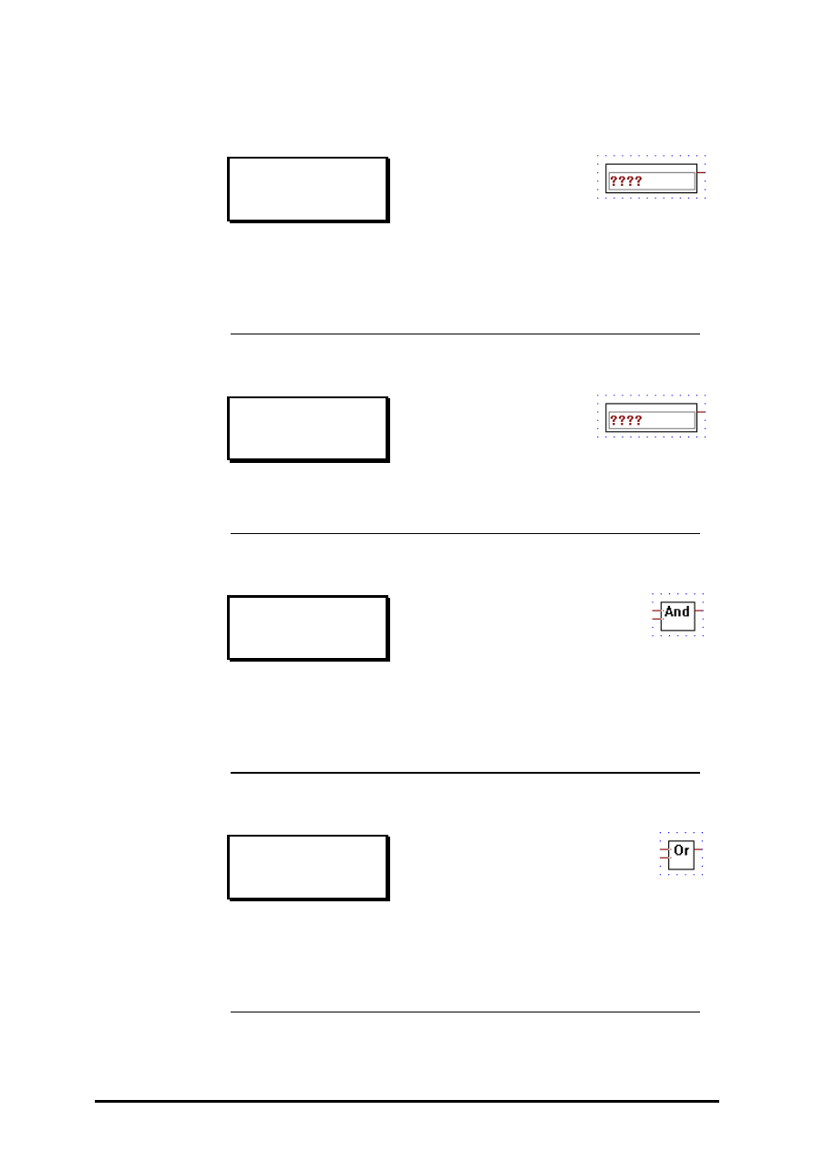
= I7:
= Slc integer format
Output: = Out: integer format
−
Err: binary format
Transfers the input "In" to "Out". The input "In" transfered is selected
via the input "Slc" ( e.g. when Slc == 0 transfers I0, when Slc == 5
transfers I5...).
Stretchable from 2 to 8 inputs "In".
When "Slc" is out of range (i.e. "Slc" < 0 or "Slc" > n), "Out" outputs
0 and "Err" is set high.

Integer arithmetic
FUPLA and KOPLA functions
Page 4-66
SAIA AG
(P-4406-E.DOC)
26/749 E1
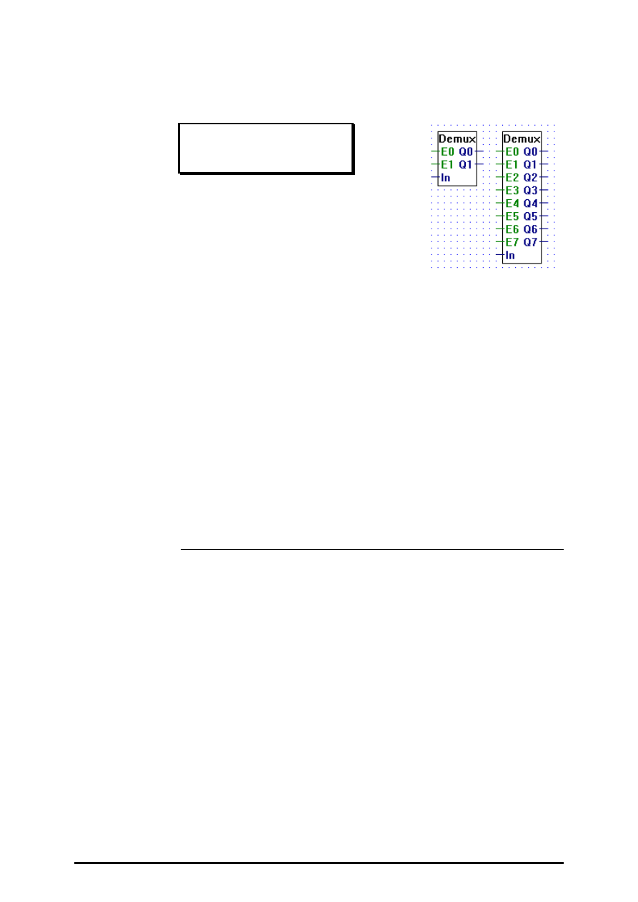
4.4.6.28
Demultiplexer with binary selection
Demux bin selection
[_idemux]
Inputs:
−
E0:
¦
binary format
−
E7:
= In:
integer format
Outputs:= Q0:
¦
integer format
= Q7:
Transfers input In to an outputs Q0..Q7 when its corresponding enable
input E0..E7 is high.
Stretchable from 2 to 8 inputs.
When an enable line is low, its corresponding output Q0..Q7 is set low.

FUPLA and KOPLA functions
Integer arithmetic
26/749 E1
(P-4406-E.DOC)
SAIA AG
Page 4-67
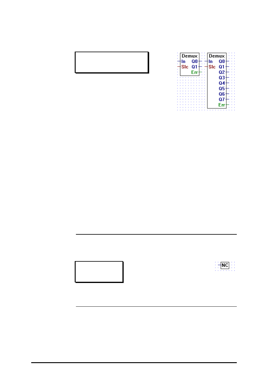
4.4.6.29
Demultiplexer with integer selection
Demux int selection
[_idemux2]
Inputs: = In:
integer format
= Slc: integer format
Outputs:= Q0
integer format
¦
= Q7
integer format
−
Err: binary format
Transfers its integer input "In" to a selected output (Q0..Qn). Outputs
are selected via the input "Slc". E.g. when "Slc" == 1 the input "In" is
transfered to "Q1".
When not selected an output is set to 0.
Stretchable from 2 to 8 outputs.
Err goes high only when "Slc" is out of range, i.e. when "Slc" < 0 or
when "Slc" > n.
Integer arithmetic
FUPLA and KOPLA functions
Page 4-68
SAIA AG
(P-4406-E.DOC)
26/749 E1
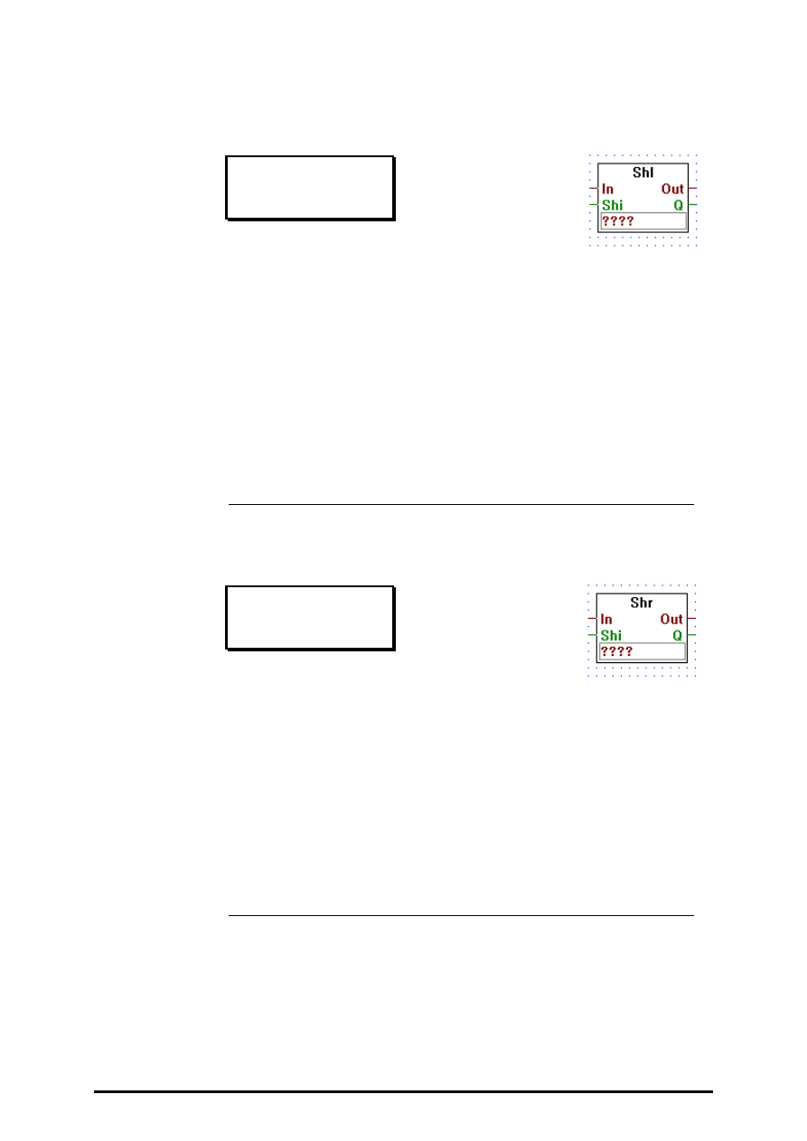
4.4.6.30
Shift left
Shift left
[_ishftl2]
Inputs: = In:
Input (integer format)
−
Shi: Shift (binary format)
Outputs:= Out: Output (integer format)
−
Q:
Output (binary format)
Outputs to Out the integer input value from In shifted left by the num-
ber of bits indicated by the constant written in the edit-field.
The value of Q is set to the value of the last bit shifted out. The input
Shi is the value to be shifted in to bit 0.
4.4.6.31
Shift right
Shift right
[_ishftr2]
Inputs: = In:
Input (integer format)
−
Shi: Shift (binary format)
Outputs:= Out: Output (integer format)
−
Q:
Output (binary format)
Outputs to Out the integer input value from In shifted right by the
number of bits indicated by the constant written in the edit-field.
The value of Q is set to the value of the last bit shifted out. The input
Shi is the value to be shifted in to bit 31.
FUPLA and KOPLA functions
Integer arithmetic
26/749 E1
(P-4406-E.DOC)
SAIA AG
Page 4-69
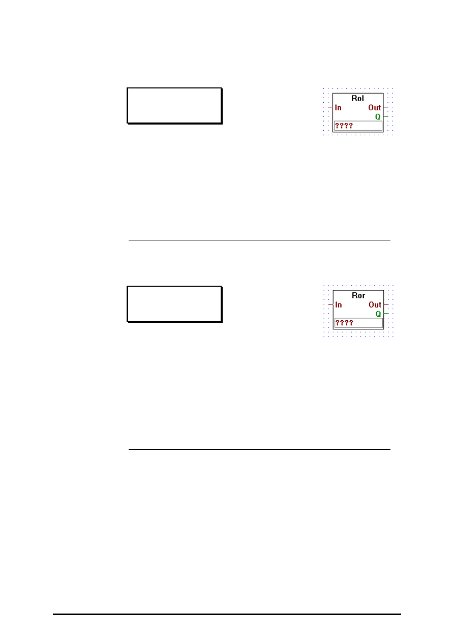
4.4.6.32
Rotate left
Rotate left
[_irotlf2]
Inputs: = In:
Input (integer format)
Outputs:= Out: Output (integer format)
−
Q:
Output (binary format)
Outputs to Out the integer input value from In rotated left by the num-
ber of bits indicated by the constant written in the edit-field.The value
of Q is set to the value of the last bit rotated.
4.4.6.33
Rotate right
Rotate right
[_irotri2]
Inputs: = In:
Input (integer format)
Outputs:= Out: Output (integer format)
−
Q:
Output (binary format)
Outputs to Out the integer input value from In rotated right by the
number of bits indicated by the constant written in the edit-field.
The value of Q is set to the value of the last bit rotated.
Integer arithmetic
FUPLA and KOPLA functions
Page 4-70
SAIA AG
(P-4406-E.DOC)
26/749 E1
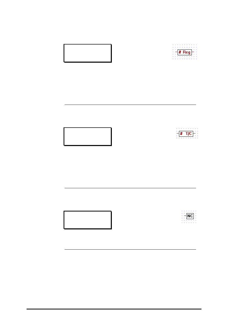
4.4.6.34
Register indirect
Register indirect
[_iregin]
Inputs/Outputs: = all
→
integer format.
Outputs the value in register #.
E.g. if the # input is 5, then the value in register 5 is output.
4.4.6.35
T/C indirect
T/C indirect
[_itcind]
Inputs/Outputs: = all
→
integer format.
Outputs the value of timer/counter #.
E.g if the # input is 5, then the value in timer/counter 5 is output.
4.4.6.36
Not connected
Not connected
[_inotcn]
The "Not Connected" box, terminates unused integer outputs.

FUPLA and KOPLA functions
Floating point arithmetic
26/749 E1
(P-4407-E.DOC)
SAIA AG
Page 4-71
4.4.7
Floating point arithmetic
[sfupfloa]
4.4.7.1
Add
Add
[_fadd2]
Inputs/Outputs:
−
all
→
floating point format
Adds the input values and transfers the result to the output.
Stretchable from 2 to 8 inputs.
4.4.7.2
Subtract
Subtract
[_fsub]
Inputs/Outputs:
−
all
→
floating point format
Outputs the result of the upper input minus the lower.
4.4.7.3
Multiply
Multiply
[_fmul]
Inputs/Outputs:
−
all
→
floating point format
Outputs the result of the multiplication of its two inputs .
Floating point arithmetic
FUPLA and KOPLA functions
Page 4-72
SAIA AG
(P-4407-E.DOC)
26/749 E1
4.4.7.4
Divide
Divide
[_fdiv]
Inputs/Outputs:
−
all
→
floating point format
O
utputs the result of the upper input divided by the lower
4.4.7.5
Square root
Square root
[_fsqr]
Inputs/Outputs:
−
all
→
floating point format
Outputs the square root of its input.
4.4.7.6
Average
Average
[_faverage]
Inputs/Outputs:
−
all
→
floating point format
Ouputs the average of its input values.
Stretchable from 2 to 8 inputs.
4.4.7.7
Constant
Constant
[_fconst]
Outputs the floating-point constant written in the entry-field.
FUPLA and KOPLA functions
Floating point arithmetic
26/749 E1
(P-4407-E.DOC)
SAIA AG
Page 4-73
4.4.7.8
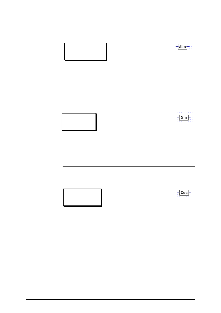
Absolute
Absolute
[_fabs ]
Inputs/Outputs:
−
all
→
floating point format
Outputs the absolute value of the input.
4.4.7.9
Sinus
Sinus
[_fsin]
Inputs/Outputs:
−
all
→
floating point format
Outputs the sine of ist input. The input is assumed to be in radians
4.4.7.10
Cosine
Cosine
[_fcos]
Inputs/Outputs:
−
all
→
floating point format
Outputs the cosine of its input. The input is assumed to be in radians.

Floating point arithmetic
FUPLA and KOPLA functions
Page 4-74
SAIA AG
(P-4407-E.DOC)
26/749 E1
4.4.7.11
ARC tangent
ARC tangent
[_fatan]
Inputs/Outputs:
−
all
→
floating point format
Outputs the arc tangent of its input. The output is in radians.
4.4.7.12
Natural exponent
Natural exponent
[_fexp]
Inputs/Outputs:
−
all
→
floating point format
Outputs 'e' to the power of the input.
4.4.7.13
Natural log
Natural log
[_fln]
Inputs/Outputs:
−
all
→
floating point format
Outputs the natural logarithm of the input.
FUPLA and KOPLA functions
Floating point arithmetic
26/749 E1
(P-4407-E.DOC)
SAIA AG
Page 4-75
4.4.7.14
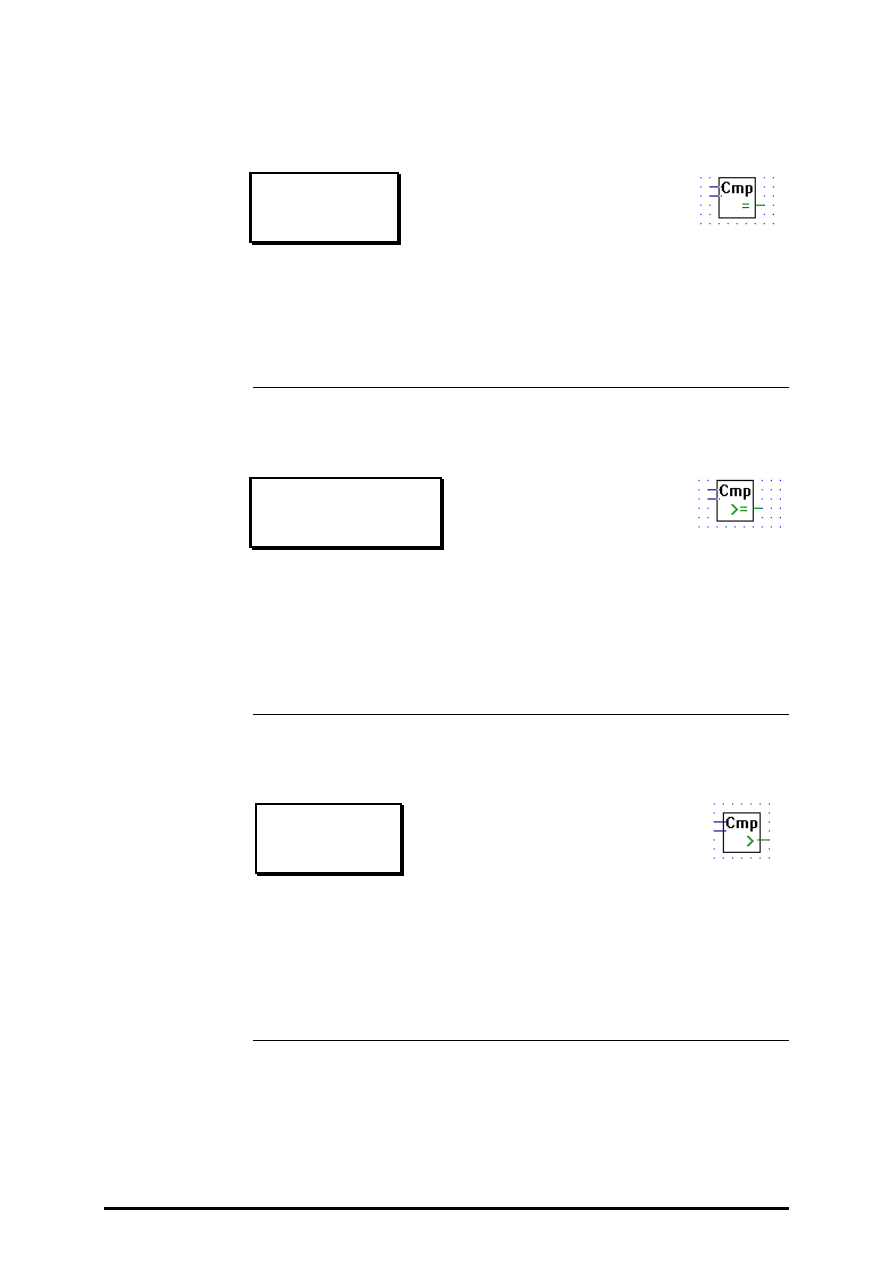
Is equal to
Is equal to
[_fcmpeq]
Inputs: all
→
floating point format
Output: binary format
Outputs binary high when both inputs are equal, else outputs binary low
4.4.7.15
Is greater or equal to
Is greater or equal to
[_fcmpge]
Inputs: all
→
floating point format
Output:
binary format
Outputs binary high when the upper input is greater or equal to the lower
input, else outputs binary low.
4.4.7.16
Is greater than
Is greater than
[_fcmpgt]
Inputs: all
→
floating point format
Output: binary format
Outputs binary high when the upper input is greater than the lower input,
else outputs binary low.
Floating point arithmetic
FUPLA and KOPLA functions
Page 4-76
SAIA AG
(P-4407-E.DOC)
26/749 E1
4.4.7.17
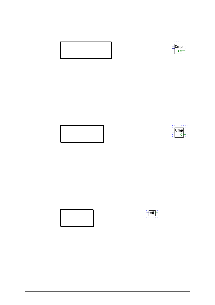
Is smaller or equal to
Is smaller or equal to
[_fcmpse]
Inputs: all
→
floating point format
Output: binary format
Outputs binary high when the upper input is less than or equal to the
lower input, else outputs binary low.
4.4.7.18
Is smaller than
Is smaller than
[_fcmpst]
Inputs: all
→
floating point format
Output:
binary format
Outputs binary high when the upper input is less than the lower input, else
outputs binary low.
4.4.7.19
Is zero
Is zero
[_fiszero]
Input:
floating point format
Output: binary format
Outputs high when its floating-point input is zero, else output low.
FUPLA and KOPLA functions
Floating point arithmetic
26/749 E1
(P-4407-E.DOC)
SAIA AG
Page 4-77
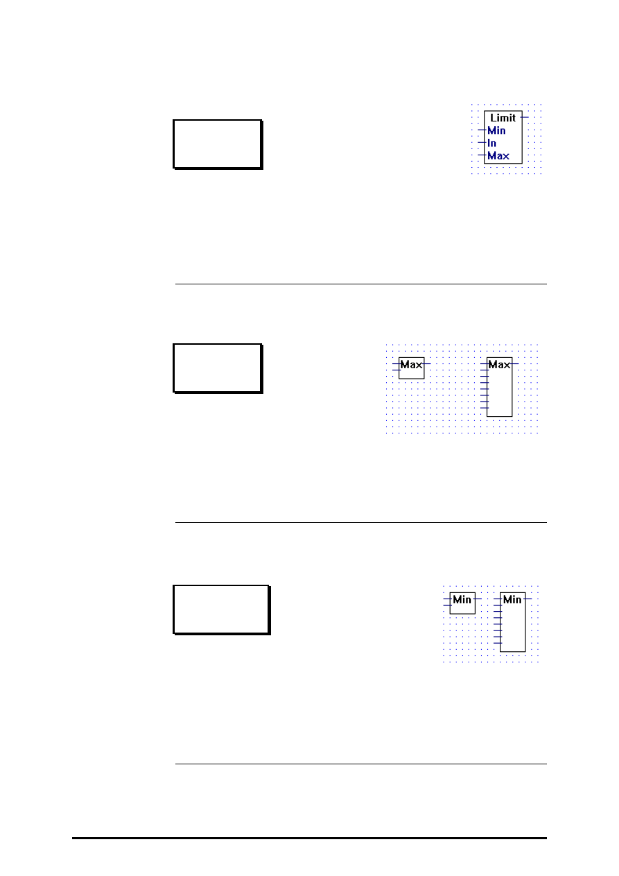
4.4.7.20
Limit
Limit
[_flimit]
Inputs/Outputs:
−
all
→
floating point format
Outputs the input value In. The output value is limited between Max and
Min.
4.4.7.21
Maximum
Maximum
[_fmax2]
Inputs/Outputs:
−
all
→
floating point format
Outputs the largest input value.
Stretchable from 2 to 8 inputs.
4.4.7.22
Minimum
Minimum
[_fmin2]
Inputs/Outputs:
−
all
→
floating point format
Outputs the smallest input value.
Stretchable from 2 to 8 inputs.

Floating point arithmetic
FUPLA and KOPLA functions
Page 4-78
SAIA AG
(P-4407-E.DOC)
26/749 E1
4.4.7.23
Move
Move
[_fmove]
Inputs/Outputs:
−
all
→
floating point format
Outputs its floating point input, used to connect an input label directly to
an output label.
4.4.7.24
Move when enabled
Move when enabled
[_fmovee]
Inputs:
−
En: Enable (binary format)
−
In:
Input (floating point format)
Output:
−
Out: Output (floating point format)
Outputs its input when the enable input is high. If "En" = L, the output
value is zero.

FUPLA and KOPLA functions
Floating point arithmetic
26/749 E1
(P-4407-E.DOC)
SAIA AG
Page 4-79
4.4.7.25
Move and store
Move and store
[_fmoves]
Inputs: > Sto Store (binary format)
−
In
Input (floating point format)
Output:
−
Out Output (floating point format)
Stores its input in an internal register when Sto goes from low to high.
Always outputs the contents of its internal register.
Floating point arithmetic
FUPLA and KOPLA functions
Page 4-80
SAIA AG
(P-4407-E.DOC)
26/749 E1
4.4.7.26
Switch
Switch
[_fswitch]
Inputs:
−
all:
→
floating point format
Outputs:
−
Out:
→
floating point format
−
QDf:
→
binary value
When the input "Ref" is equal to one of its input "=n" it transfers the cor-
responding input "In" to the output.
When there are no input "=n" equal to "Ref" then the input "Def" is out-
put to "Out" and the output "QDf" is set high.
Stretchable from I1 to I7.
Input I0 as higher priority than I7. When more than one input "=n" equals
the input "Ref", than only the input with the highest priority is transfered.
FUPLA and KOPLA functions
Floating point arithmetic
26/749 E1
(P-4407-E.DOC)
SAIA AG
Page 4-81
4.4.7.27
Multiplexer with binary selection
Mux with bin selection
[_fmux]
Inputs:
−
I0:
¦
floating point format
−
I7:
−
E0:
¦
binary format
−
E7:
Output:
−
Out: floating point format
Transfers an input I0..I7 to the output when the corresponding enable sig-
nal E0..E1 is high.
Stretchable from 2 to 8 inputs.
If all enable inputs are low, a low is output.
The enable line E0 has the highest priority and E7 has the lowest. There-
fore if one or more enable lines are activated at the same time, the input
associated with the highest priority enable line will be output.

Floating point arithmetic
FUPLA and KOPLA functions
Page 4-82
SAIA AG
(P-4407-E.DOC)
26/749 E1
4.4.7.28
Multiplexer with integer selection
Mux with int selection
[_fmux2]
Inputs:
−
I0:
¦
floating point format
−
I7:
= Slc: integer format
Outputs:
−
Out: floating point format
−
Err: binay format
Transfers the input "In" to "Out". The input "In" transfered is selected via
the input "Slc" ( e.g. when Slc == 0 transfers I0, when Slc == 5 transfers
I5...).
Stretchable from 2 to 8 inputs "In".
When "Slc" is out of range (i.e. "Slc" < 0 or "Slc" > n), "Out" outputs 0.0
and "Err" is set high.
FUPLA and KOPLA functions
Floating point arithmetic
26/749 E1
(P-4407-E.DOC)
SAIA AG
Page 4-83
4.4.7.29
Demultiplexer with binary selection
Demux with bin selection
[_fdemux]
Inputs:
−
E0:
¦
binary format
−
E7:
= In:
floating point format
Outputs:
−
Q0:
¦
floating point format
−
Q7:
Transfers input In to output Qn when the corresponding enable line En is
high.
Stretchable from 2 to 8.
When an enable line E0..E7 is low, its corresponding output Q0..Q7 is set
low.
Floating point arithmetic
FUPLA and KOPLA functions
Page 4-84
SAIA AG
(P-4407-E.DOC)
26/749 E1
4.4.7.30
Demultiplexer with integer selection
Demux with int selection
[_fdemux2]
Inputs:
−
In:
floating point format
= Slc: integer format
Outputs:
−
Q0:
¦
floating point format
−
Q7:
−
Err: binary format
Transfers its integer input "In" to a selected output (Q0..Qn). Outputs are
selected via the input "Slc". E.g. when "Slc" == 1 the input "In" is trans-
fered to "Q1".
When not selected an output is set to 0.0.
Stretchable from 2 to 8 outputs.
Err goes high only when "Slc" is out of range, i.e. when "Slc" < 0 or when
"Slc" > n.
4.4.7.31
Not connected
Not connected
[_Fnotcn]
The "Not Connected" box, terminates unused floating point outputs.
FUPLA and KOPLA functions
Converters (binary - integer - floating point)
26/749 E1
(P-4408-E.DOC)
SAIA AG
Page 4-85
4.4.8
Converters (binary-integer-floating point)
[sfupconv]
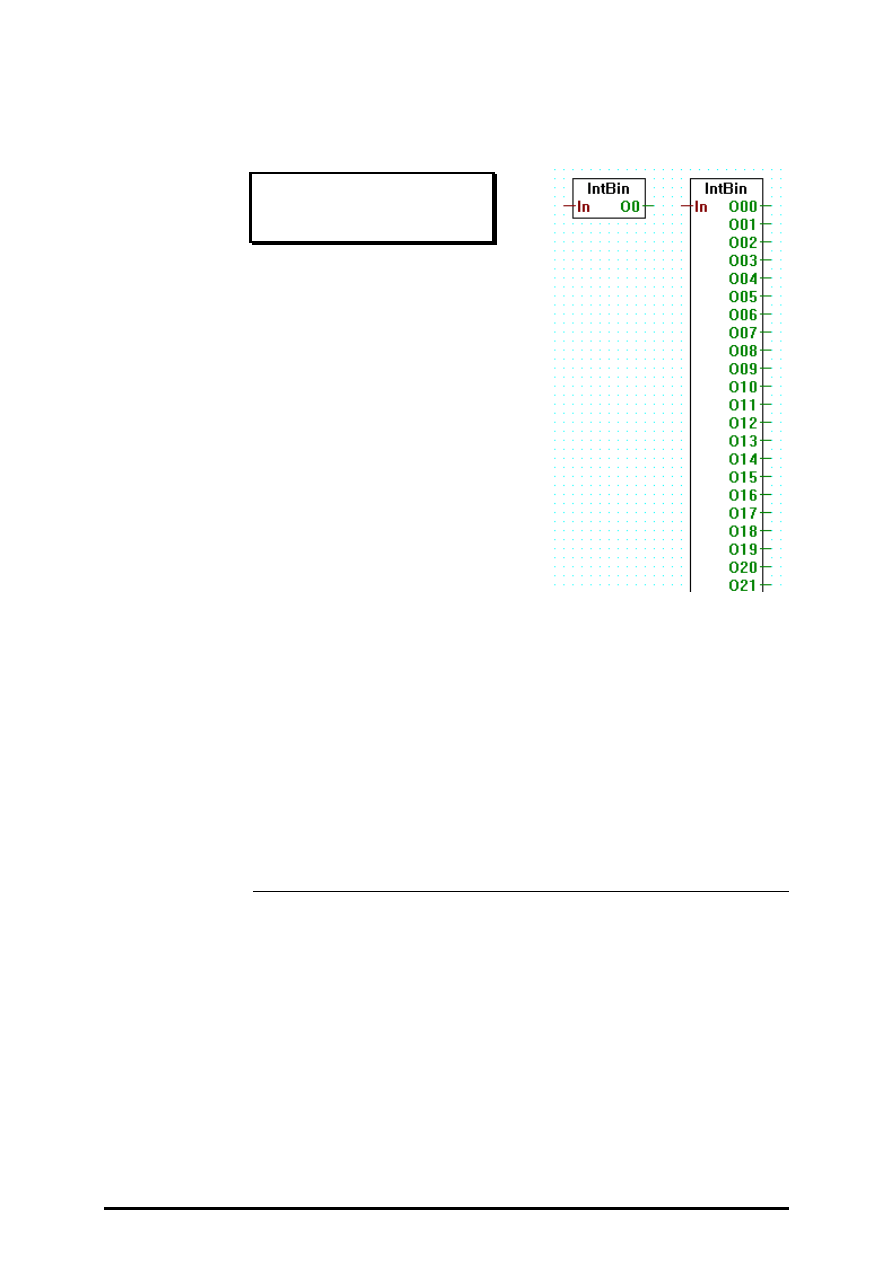
4.4.8.1
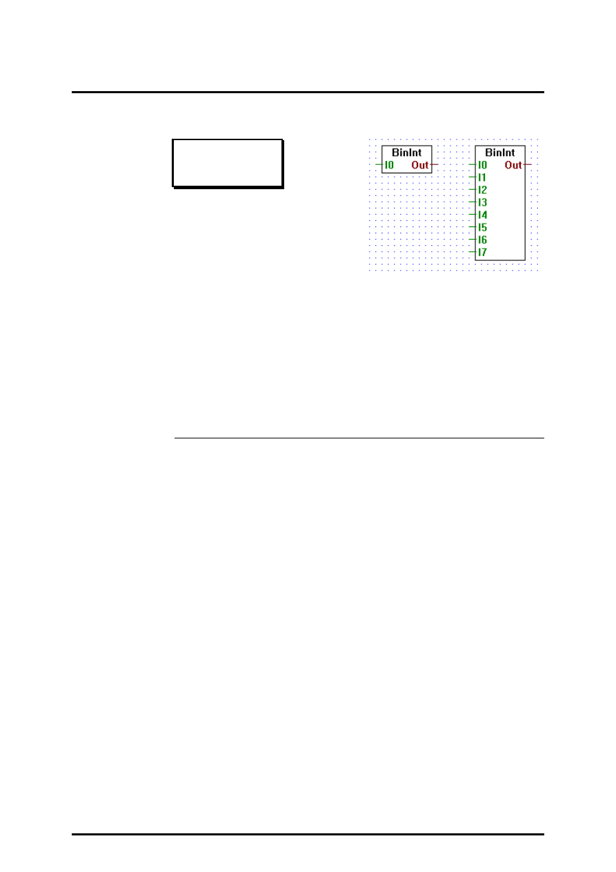
Binary to integer 1-8 I/O/F
Bin to int 1-8
[_conbiti]
Inputs:
−
I0
¦
binary format
−
I7
Output: = Out integer format
Transfers input I0..I7 to the bit 0..bit 7 of the output
integer. All other bits of the output integer are cleared.Stretchable from 1
to 8 inputs.
Converters (binary - integer - floating point)
FUPLA and KOPLA functions
Page 4-86
SAIA AG
(P-4408-E.DOC)
26/749 E1
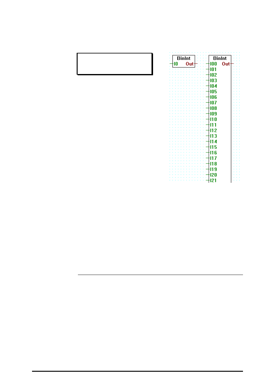
4.4.8.2
Binary to integer 1-24 I/O/F
Bin to int 1-24
[_conbitim]
Inputs:
−
I0:
¦
binary format
−
I23
Output:
= Out integer format
Transfers input I0..I23 to the bit 0..bit 23 of the output integer. All other
bits of the output integer are cleared.
Stretchable from 1 to 23 inputs.
For more than 24 bits please use the Fbox 'Bin to int quick'.
FUPLA and KOPLA functions
Converters (binary - integer - floating point)
26/749 E1
(P-4408-E.DOC)
SAIA AG
Page 4-87
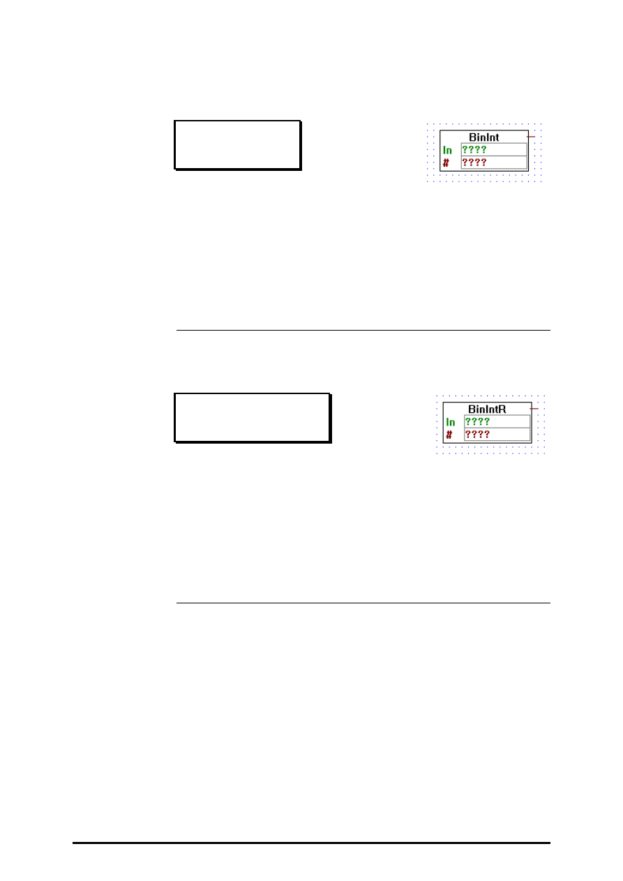
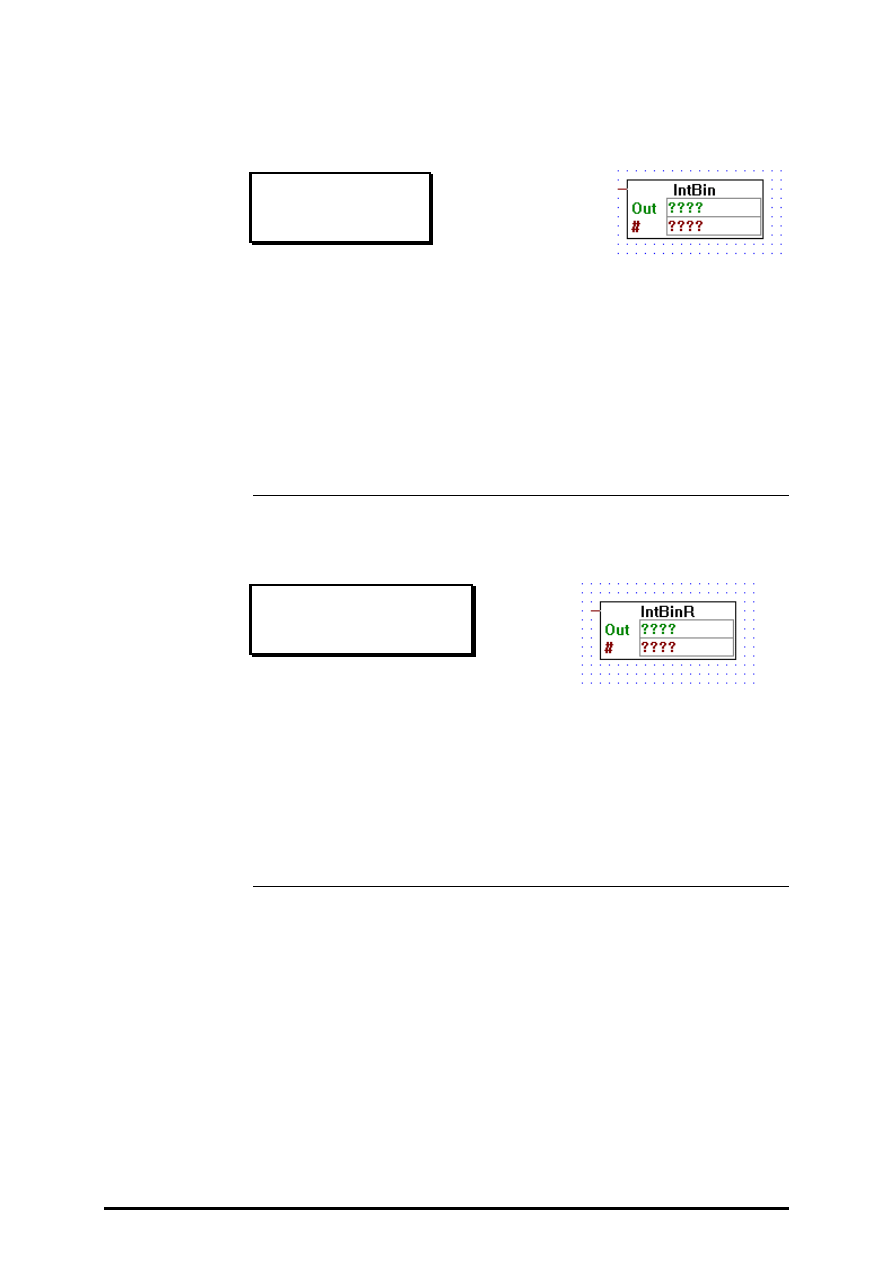
4.4.8.3
Binary to integer quick
Bin to int quick
[_conbitiq]
Output: =
→
integer format
Moves a sequence of bits into an integer. The first entry-field indicates the
source address (I, O, F) of the binary sequence, and the second entry-field
(
#
) indicates the number of bits to be moved.
The lowest addressed bit becomes the least significant bit in the destina-
tion integer. This is contrary to the PCA.
4.4.8.4
Binary to integer reverse quick
Bin to int reverse quick
[_conbitiqr]
Output: =
→
integer format
Moves a sequence of bits to an integer. The first entry-field indicates the
source address (I, O, F) of the binary sequence, and the second entry-field
(
#
) indicates the number of bits to be moved.
The highest addressed bit becomes the least significant bit in the destina-
tion integer. This is the same as for the PCA.
Converters (binary - integer - floating point)
FUPLA and KOPLA functions
Page 4-88
SAIA AG
(P-4408-E.DOC)
26/749 E1
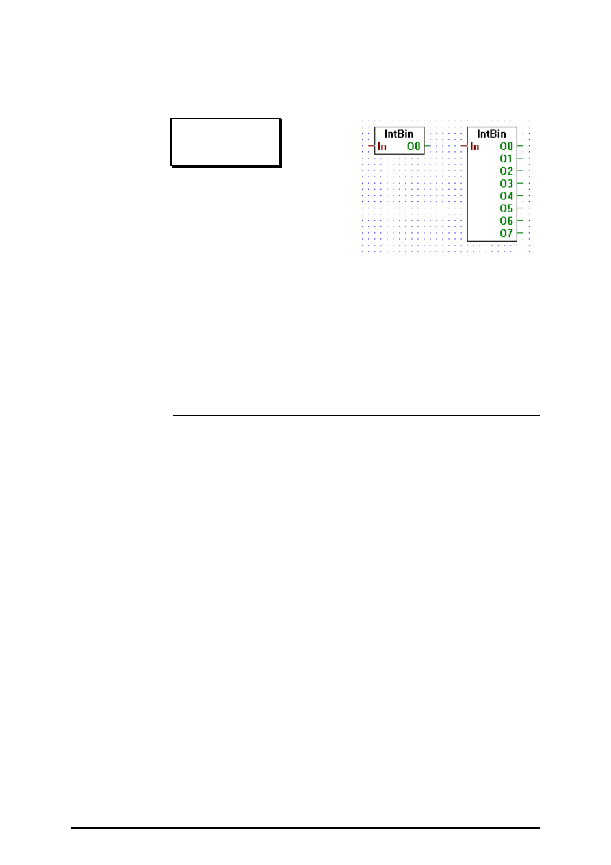
4.4.8.5
Integer to binary 1-8 O/F
Int to bin 1-8
[_conbito]
Input:
= In:
integer format
Outputs
−
O0:
¦
binary format
−
O7:
Transfers bits 0..7 of integer input In to binary outputs O0..7.
Stretchable from 1 to 8 bits.
FUPLA and KOPLA functions
Converters (binary - integer - floating point)
26/749 E1
(P-4408-E.DOC)
SAIA AG
Page 4-89
4.4.8.6
Integer to binary 1-24 O/F
Int to bin 1-24
[_conbitom]
Input:
= In:
integer format
Outputs:
−
O0
binary format
−
023
Transfers bits 0..23 of integer input In to binary outputs O0..23.
Stretchable from 1 to 24 bits.
For more than 24 bits please use the Fbox 'Int to bin quick'.
Converters (binary - integer - floating point)
FUPLA and KOPLA functions
Page 4-90
SAIA AG
(P-4408-E.DOC)
26/749 E1
4.4.8.7
Integer to binary quick
Int to bin quick
[_conbitoq]
Input:
=
→
integer format
Moves an integer value into a sequence of bits. The first entry-field indi-
cates the destination address (O, F) of the binary sequence, and the sec-
ond entry-field (
#
) indicates the number of bits to be moved.
The least significant bit of the incoming integer is moved to the lowest
addressed bit. This is contrary to the PCA.
4.4.8.8
Integer to binary reverse quick
Int to bin reverse quick
[_conbitoqr]
Input:
=
→
integer format
Moves an integer value into a sequence of bits. The first entry-field indi-
cates the destination address (O, F) of the binary sequence, and the sec-
ond entry-field (
#
) indicates the number of bits to be moved.
The least significant bit of the incoming integer is moved to the highest
addressed bit. This is the same as the PCA.
FUPLA and KOPLA functions
Converters (binary - integer - floating point)
26/749 E1
(P-4408-E.DOC)
SAIA AG
Page 4-91
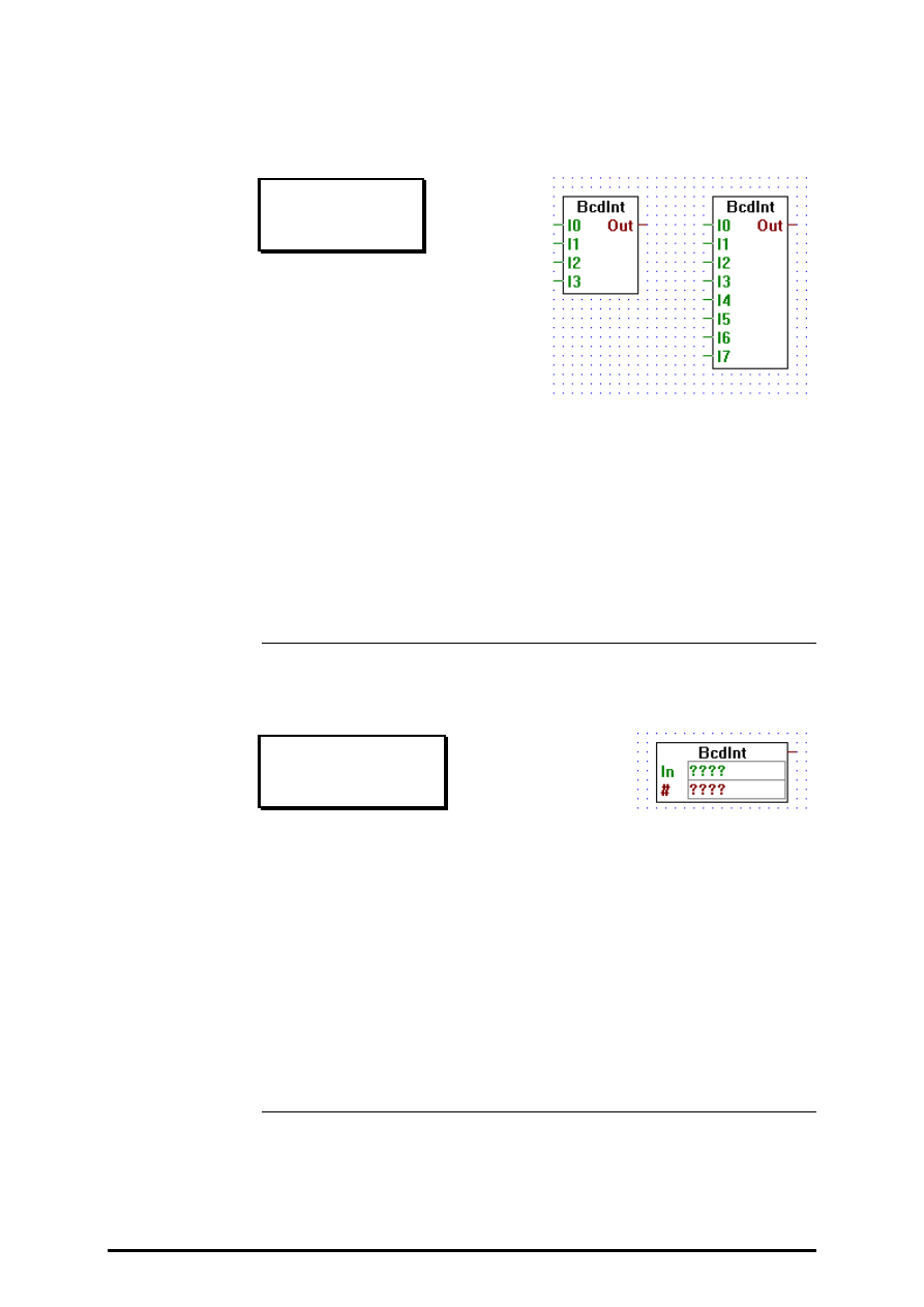
4.4.8.9
BCD to integer
BCD to int
[_condigi]
Inputs:
−
I0:
¦
binary format
−
I7:
Output: = Out: integer format
Reads a 4-bit BCD digit, and outputs it as an integer.
Stretchable, 4 or 8 inputs.
Input I0 is the least significant bit, I7 is the most significant.
4.4.8.10
BCD to integer quick
BCD to int quick
[_condigiq]
Output: =
→
integer format
Reads Binary Coded Decimal (BCD) digits from Inputs, Outputs or Flags,
and outputs them as an integer value.
The first operand is the address of the base address of the Inputs, Outputs
or Flag, and the second operand indicates how many digits should be
read.
The lowest addressed bit becomes the least significant bit of the least sig-
nificant digit in the destination integer. This is contrary to the PCA.
Converters (binary - integer - floating point)
FUPLA and KOPLA functions
Page 4-92
SAIA AG
(P-4408-E.DOC)
26/749 E1
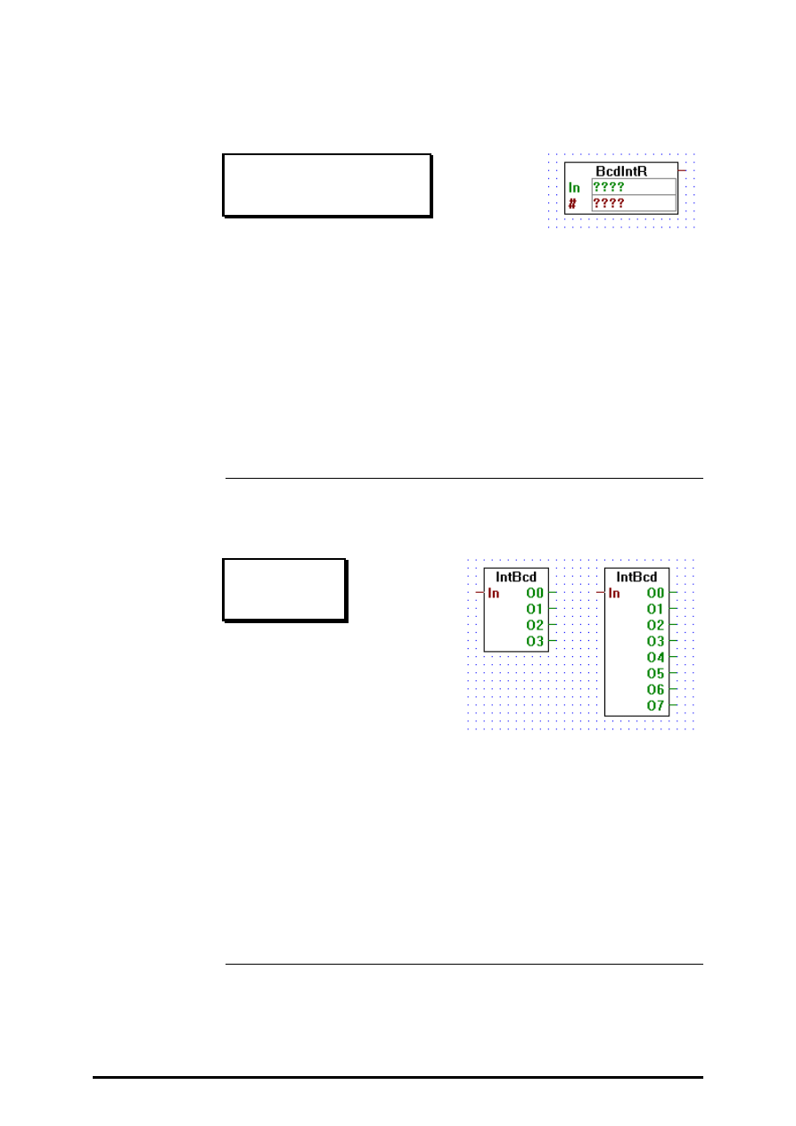
4.4.8.11
BCD to integer reverse quick
BCD to int reverse quick
[_condigiqr]
Output: =
→
integer format
Help=Reads Binary Coded Decimal (BCD) digits from Inputs, Outputs or
Flags, and outputs them as an integer value.
The first operand is the address of the base address of the Inputs, Outputs
or Flag, and the second operand indicates how many digits should be
read.
The lowest addressed bit is moved to the most significant bit of the inte-
ger output. This is the same as the PCA.
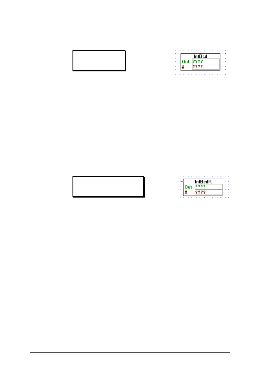
4.4.8.12
Integer to BCD
Int to BCD
[_condigo]
Input:
= In:
integer format
Outputs
−
O0:
¦
binary format
−
O7:
Converts integer value In into a 4 or 8-bit BCD value.
Stretchable, 4 or 8 outputs.
Output O0 is the least significant bit, O7 is the most significant.
FUPLA and KOPLA functions
Converters (binary - integer - floating point)
26/749 E1
(P-4408-E.DOC)
SAIA AG
Page 4-93
4.4.8.13
Integer to BCD quick
Int to BCD quick
[_condigoq]
Input:
=
→
integer format
Help=Moves BCD digits from an integer to a sequence of Outputs or
Flags.
The first operand is the address of the base address of the Outputs or
Flag, and the second operand indicates how many digits should be moved.
The lowest addressed bit becomes the least significant bit of the least sig-
nificant BCD digit. This is contrary to the PCA.
4.4.8.14
Integer to BCD reverse quick
Int to BCD reverse quick
[_condigoqr]
Input:
=
→
integer format
Moves BCD digits from an integer to a sequence of Outputs or Flags.
The first operand is the address of the base address of the Outputs or
Flag, and the second operand indicates how many digits should be moved.
The lowest integer bit becomes the highest addressed bit in the binary se-
quence. This is the same as the PCA.
Converters (binary - integer - floating point)
FUPLA and KOPLA functions
Page 4-94
SAIA AG
(P-4408-E.DOC)
26/749 E1
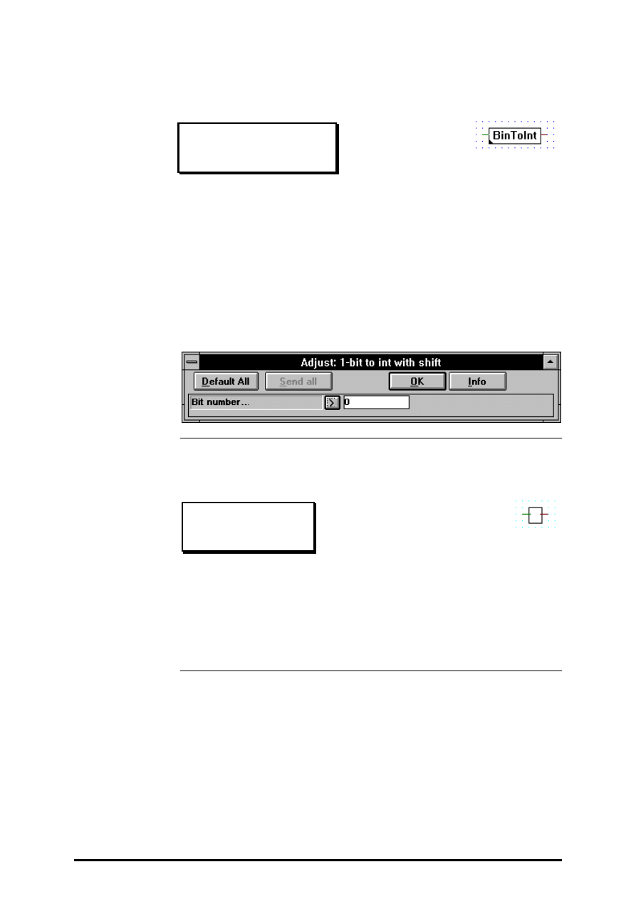
4.4.8.15
1-bit to integer with shift
1-bit to int with shift
[_conbintoi]
Input:
−
→
binary format
Output: =
→
integer format
Moves the input binary value in a specified bit of the output integer value.
All other bits are set to 0.
The bit number chosen is specified by the "Bit number" variable in the
adjust variable window.
4.4.8.16
1-bit to integer LSB
1-bit to int LSB
[_conbimove]
Input:
−
→
binary format
Output: =
→
integer format
Outputs a 0 to the integer value when the input is LOW (0), else it out-
puts 1 to it.
FUPLA and KOPLA functions
Converters (binary - integer - floating point)
26/749 E1
(P-4408-E.DOC)
SAIA AG
Page 4-95
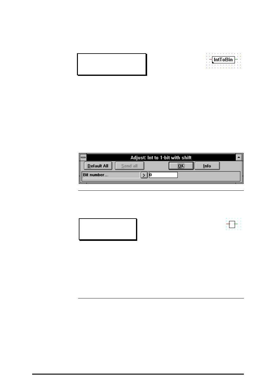
4.4.8.17
Integer to 1-bit with shift
Int to 1-bit with shift
[_conitobin]
Input:
−
→
integer format
Output: =
→
binary format
Moves a specified bit from the input integer value in the output binary
value.
The bit number chosen is specified by the "Bit number" variable in the
adjust variable window.
4.4.8.18
Integer LSB to 1-bit
Int LSB to 1-bit
[_conibmove]
Input:
=
→
integer format
Output:
−
→
binary format
Transfers LOW (0) in the binary output when its integer input is 0 (or any
other even value), it transfers HIGH (1) when its integer input is 1 (or any
other odd value).
Converters (binary - integer - floating point)
FUPLA and KOPLA functions
Page 4-96
SAIA AG
(P-4408-E.DOC)
26/749 E1
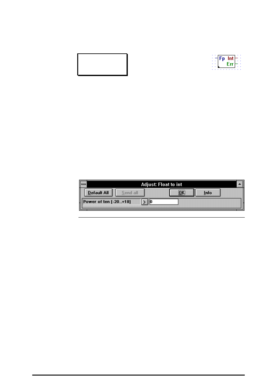
4.4.8.19
Floating point format to integer format
Float to int
[_confpi2]
Input:
−
Fp: floating point format
Outputs:= Int
integer format
−
Err binary format
Outputs the integer representation of a floating point value.
The result is multiplied by 10 to the power of the adjustable parameter.
E.g. if the input is 1234.56 and the entry field is -2, the integer result will
be 12.
Err is set high if overflow occurs.
FUPLA and KOPLA functions
Converters (binary - integer - floating point)
26/749 E1
(P-4408-E.DOC)
SAIA AG
Page 4-97
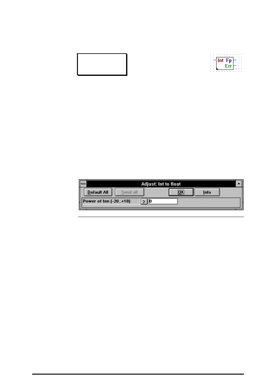
4.4.8.20
Integer format to floating point format
Int to float
[_conifp2]
Input:
−
Int: integer format
Outputs:= Fp
floating point format
−
Err binary format
Outputs the floating point representation of an integer value.
The adjustable parameter is the power of 10 to which the integer value is
to be raised. E.g. if the entry-field is 3 and the input is 12, then the result
will be 12000.00.
Err is set high if overflow occurs.

FUPLA and KOPLA functions
Indirect addressing
26/749 E1
(P-4409-E.DOC)
SAIA AG
Page 4-99
4.4.9
Indirect addressing
[sfupindi]
This function family is used for the indirect addressing of individual re-
sources and sequences of resources. The main applications are:
•
repetitive functions with different addresses
•
selection of parameters in large tables
•
wherever flexibility is wanted in addressing
Although this function family can be used in a very universal way, it re-
quires quite disciplined programming, as careless handling can result in
addressing errors which are hard to locate. The following are the main ar-
eas for caution:
•
Incorrect value at input
#
, especially when copying.
•
Addressing errors when addresses are entered externally
(process control system, terminal, BCD input). This can be
prevented with a preceding "Limit" Fbox and a combined sig-
nal.
•
Overlap with the dynamic address ranges.
•
Timer / Counter distribution (timers become counters)
•
I/O equipment.
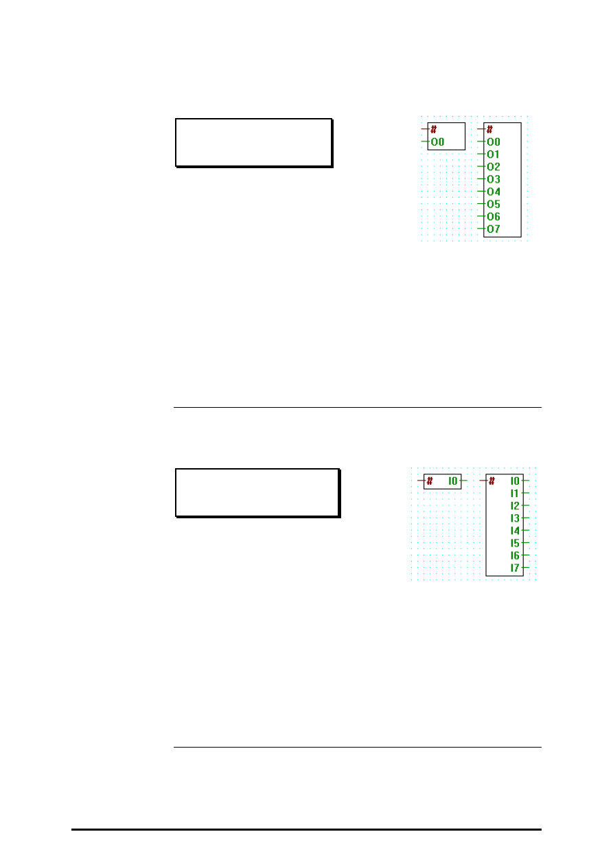
Indirect addressing
FUPLA and KOPLA functions
Page 4-100
SAIA AG
(P-4409-E.DOC)
26/749 E1
4.4.9.1
Copy to outputs
Copy to outputs
[_indioo]
Inputs:
=
#
:
address of first element (0 - 8191)
−
O0
binary format
¦
−
O7
binary format
Copy 1 to 8 variables to consecutive outputs. The address of the first
element is indirectly given with the input #.
Please read the information's on the beginning of the chapter 4.4.9.
4.4.9.2
Read from inputs
Read from inputs
[_indioi]
Input:
=
#
address of first element (0 - 8191)
Ausgänge:
−
I0
binary format
¦
−
I7
binary format
Read the content of 1 to 8 consecutive inputs or outputs. The address of
the first element is indirectly given with the input #.
Please read the information's on the beginning of the chapter 4.4.9.
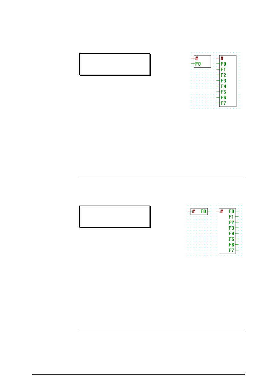
FUPLA and KOPLA functions
Indirect addressing
26/749 E1
(P-4409-E.DOC)
SAIA AG
Page 4-101
4.4.9.3
Copy to flags
Copy to flags
[_indflgo]
Inputs:
=
#
address of first element (0 - 8191)
−
F0
binary format
¦
−
F7
binary format
Copy 1 to 8 variables to consecutive flags. The address of the first ele-
ment is indirectly given with the input #.
Please read the information's on the beginning of the chapter 4.4.9.
4.4.9.4
Read from flags
Read from flags
[_indflgi]
Input:
=
#
address of first element (0 - 8191)
Outputs:
−
F0
binary format
¦
−
F7
binary fomrat
Read the content of 1 to 8 consecutive flags. The address of the first ele-
ment is indirectly given with the input #.
Please read the information's on the beginning of the chapter 4.4.9.
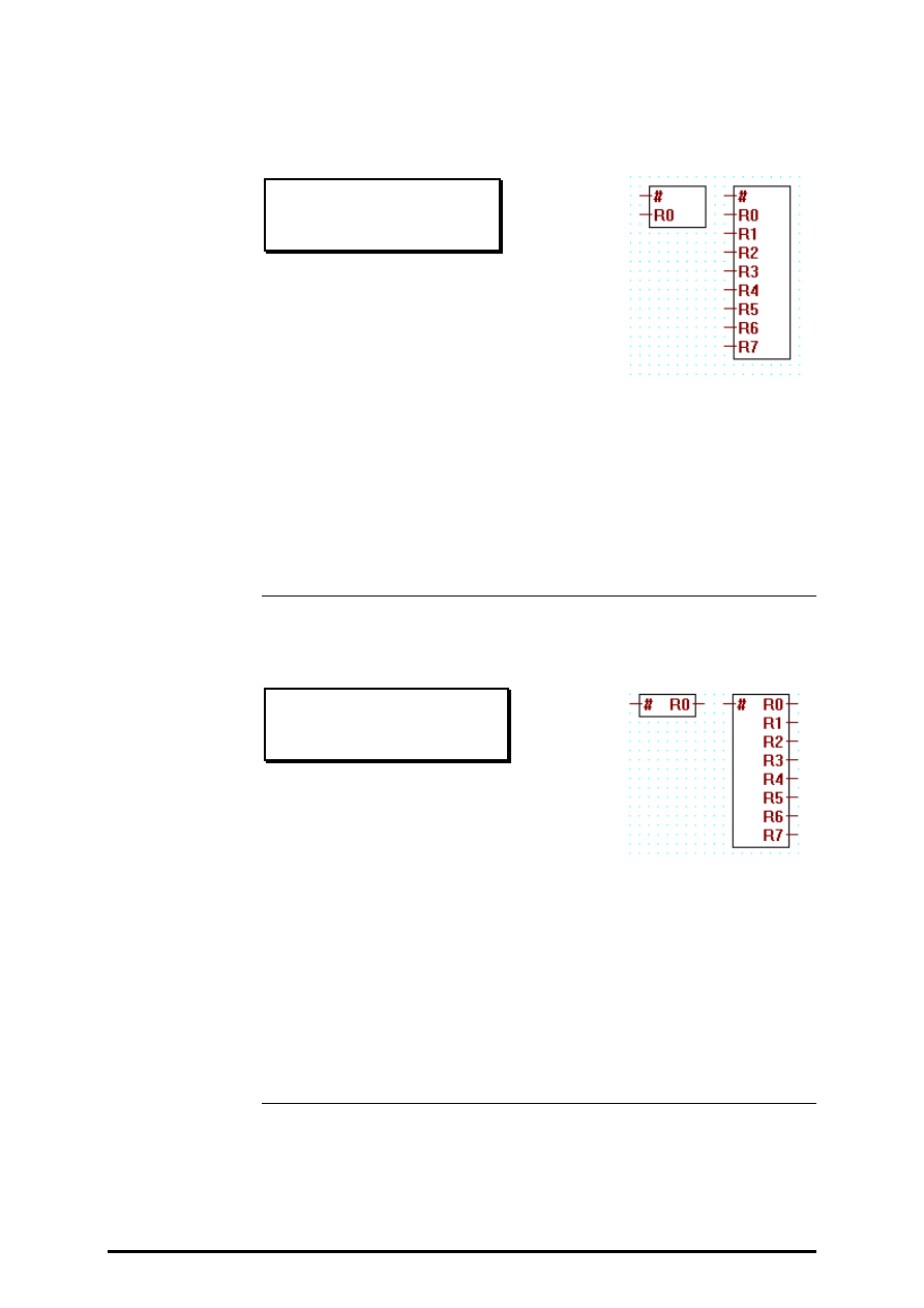
Indirect addressing
FUPLA and KOPLA functions
Page 4-102
SAIA AG
(P-4409-E.DOC)
26/749 E1
4.4.9.5
Copy to registers integer
Copy to reg. integer
[_indrego]
Inputs:
=
#
address of first element (0 - 4095)
= R0
integer format
¦
= R7
integer format
Copy 1 to 8 variables to consecutive registers. The address of the first
element is indirectly given with the input #.
Please read the information's on the beginning of the chapter 4.4.9.
4.4.9.6
Read from registers integer
Read from reg. integer
[_indregi]
Input:
=
#
address of first element (0 - 4095)
Outputs:
= R0
integer format
¦
= R7
integer format
Read the content of 1 to 8 consecutive registers. The address of the first
element is indirectly given with the input #.
Please read the information's on the beginning of the chapter 4.4.9.
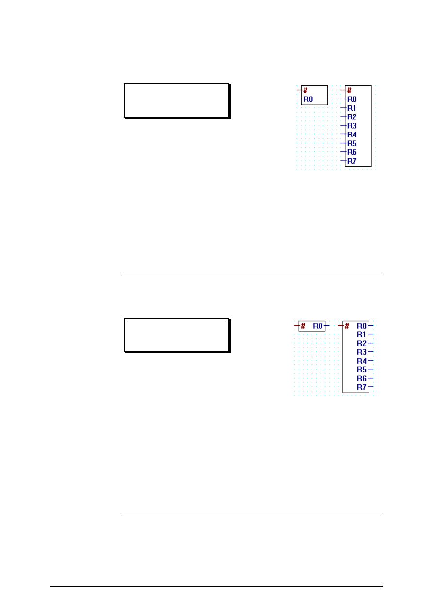
FUPLA and KOPLA functions
Indirect addressing
26/749 E1
(P-4409-E.DOC)
SAIA AG
Page 4-103
4.4.9.7
Copy to registers float
Copy to reg. float
[_indfpo]
Inputs:
=
#
address of first element (0 - 4095)
= R0
floating point format
¦
= R7
floating point format
Copy 1 to 8 variables to consecutive floating point registers. The address
of the first element is indirectly given with the input #.
Please read the information's on the beginning of the chapter 4.4.9.
4.4.9.8
Read from registers float
Read from reg. float
[_indfpi]
Input:
=
#
address of first element (0 - 4095)
Outputs:
= R0
floating point format
¦
= R7
floating point format
Read the content of 1 to 8 consecutive floating-point registers. The ad-
dress of the first element is indirectly given with the input #.
Please read the information's on the beginning of the chapter 4.4.9.
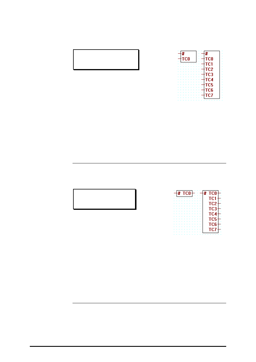
Indirect addressing
FUPLA and KOPLA functions
Page 4-104
SAIA AG
(P-4409-E.DOC)
26/749 E1
4.4.9.9
Copy toTimer/Counter
Copy toT/C
[_indtco]
Inputs:
=
#
address of first element (0 - 1599)
= TC0 integer format
¦
= TC7 integer format
Copy 1 to 8 variables to consecutive timers or counters. The address of
the first element is indirectly given with the input #.
Please read the information's on the beginning of the chapter 4.4.9.
4.4.9.10
Read from Timer/Counter
Read from T/C
[_indtci]
Input:
=
#
address of first element (0 - 1599)
Outputs:
= TC0 integer format
¦
= TC7 integer format
Read the content of 1 to 8 consecutive timers or counters. The address of
the first element is indirectly given with the input #.
Please read the information's on the beginning of the chapter 4.4.9.
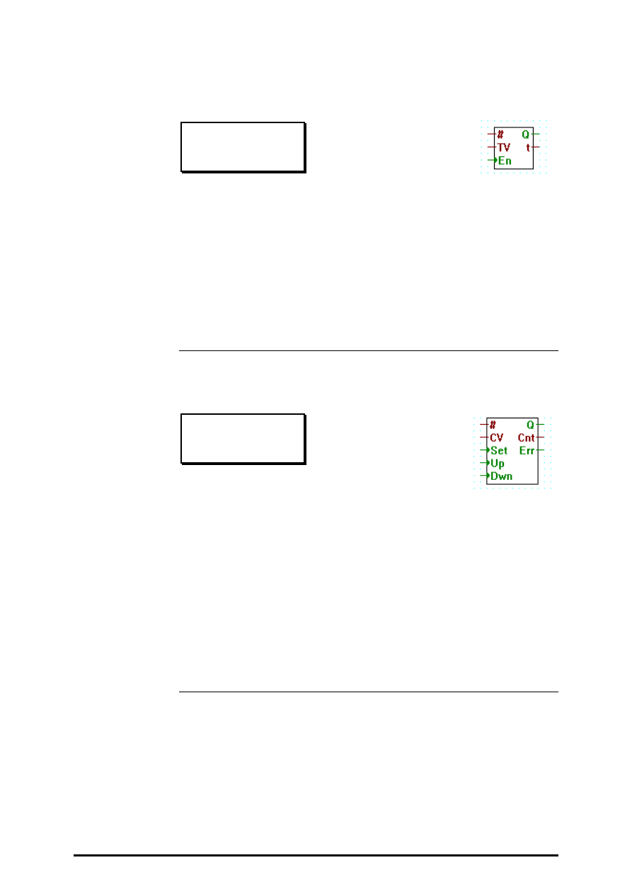
FUPLA and KOPLA functions
Indirect addressing
26/749 E1
(P-4409-E.DOC)
SAIA AG
Page 4-105
4.4.9.11
Timer with indirect addressing.
Timer
[_indtmr]
Inputs:
=
#
address of first timer
= TV Timer Value in 1/10 sec.
integer format
> En
Enable (start of timer)binary format
Outputs:
−
Q
timer output
binary format
= t
actual timer stand
integer format
Timer function with indirect address. The input # gives the address of the
timer used.
4.4.9.12
Counter with indirect addressing
Counter
[_indcnt]
Inputs:
=
#
address of first counter
= CV load value
integer format
> Set load with "CV"
binary format
> Up
increment (+1)
binary format
> Dwn decrement (
−
1)
binary format
Outputs:
−
Q
Output (H, if C > 0)
binary format
= Cnt actual counter stand
integer format
−
Err Error (overflow)
binary format
Counter function with indirect address. The input # gives the address of
the used counter.

Indirect addressing
FUPLA and KOPLA functions
Page 4-106
SAIA AG
(P-4409-E.DOC)
26/749 E1
4.4.9.13
Read logic state from Timer/Counter
Read logic state T/C
[_indtcli]
Input:
=
#
first T/C address (0 - 1599)
Outputs:
−
TC0 H/L Timer/Counter
binary format
¦
−
TC7 H/L Timer/Counter
binary format
Read the logical state of 1 to 8 consecutive timers or counters. The ad-
dress of the first element is indirectly given with the input #.
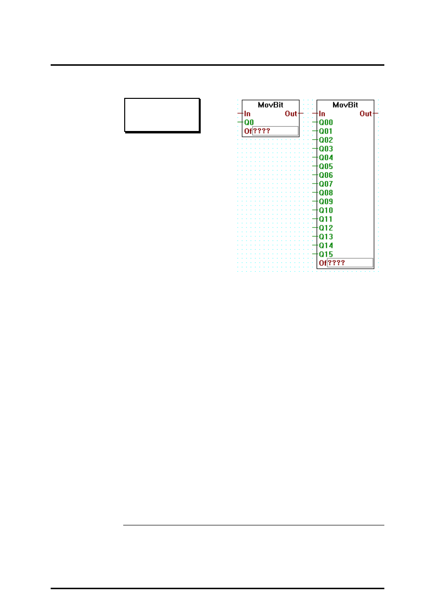
FUPLA and KOPLA functions
Move Data
26/749 E1
(P-4410-E.DOC)
SAIA AG
Page 4-107
4.4.10
Move Data
[sfupmove]
4.4.10.1
Move-In Bit
Move-In Bit
[_movebiti]
Inputs:
= In:
integer format
−
Q00: binary format (Q = Quantum) (0 or 1)
¦
−
Q15: binary format
= Of: Offset, integer format (0 -31)
Output:
= Out: integer format
Move 1 to 24 bits in a register.
The input In is combined with the bits from inputs Q0 to Q.. (last used).
The bits Q0 is moved to the location defined by the offset value Of.
The next bits used are moved in the successive locations.
All other bits are not changed. The result is copied to the output Out.
E.g. "Move-In Bit" with "Of" = 5 and inputs Q0 to Q7:
Q7 Q0
x xxxx xxx
↓
↓↓↓↓
↓↓↓
oooo oooo oooo oooo ooox xxxx xxxo oooo
31 5 0
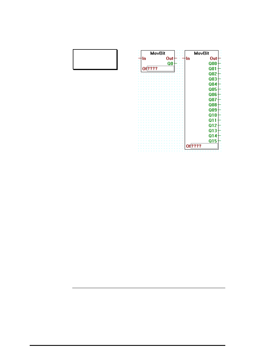
Move Data
FUPLA and KOPLA functions
Page 4-108
SAIA AG
(P4410-E.DOC)
26/749 E1
4.4.10.2
Move-Out Bit
Move-Out Bit
[_movebito]
Inputs:
= In:
integer format
= Of: Offset, integer format 0 -31)
Outputs:
= Out: integer format
−
Q00: binary format (Q = Quantum) (0 or 1)
¦
−
Q15:binary format
Bits are moved out from the value of the input In. The first bit B0 is
moved from the location defined by the offset value Of.
The next bits used are moved from successive locations.
The input In is unchanged and copied to the output Out.
E.g. "Move-Out Bit", "Of" = 5 and outputs Q0 to Q7:
31 5 0
oooo oooo oooo oooo ooox xxxx xxxo oooo
↓
↓↓↓↓
↓↓↓
x xxxx xxx
Q7 Q0
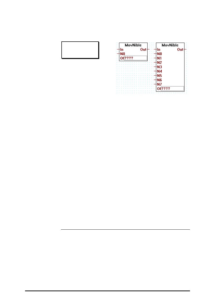
FUPLA and KOPLA functions
Move Data
26/749 E1
(P-4410-E.DOC)
SAIA AG
Page 4-109
4.4.10.3
Move-In Nibble (4 Bit binär)
Move-In Nibble
[_movenibi]
Inputs:
= In:
integer format
= N0: integer format (0 - 15)
¦
= N7: integer format
= Of: Offset, integer format (0 - 7)
Output:
= Out: integer format
Move 1 to 8 nibbles in a register.
The input In is combined with the nibbles (4 bits) from inputs N0 to N..
(last used). The LS-nibble from N0 is moved to the nibble location de-
fined by the offset value Of.
The next nibbles used are moved in the successive locations.
All other nibbles are not changed. The result is copied to the output Out.
E.g. "Move-In Nibbles" with "Of" = 3 and inputs N0 to N2:
N2 N1 N0
xxxx xxxx xxxx
↓↓↓↓
↓↓↓↓
↓↓↓↓
oooo oooo oooo oooo oooo oooo oooo oooo
Ni 7 6 5 4 3 2 1 0
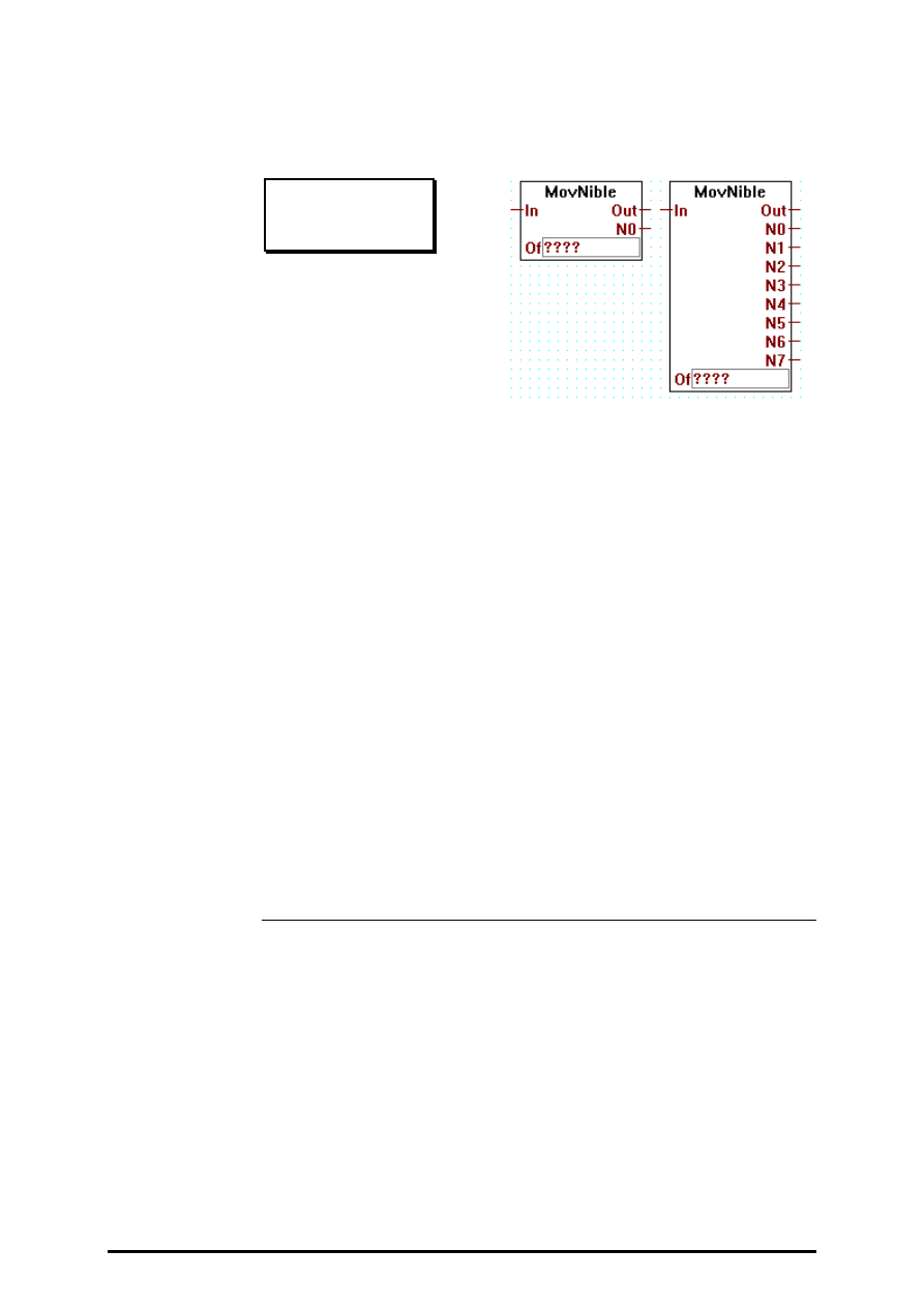
Move Data
FUPLA and KOPLA functions
Page 4-110
SAIA AG
(P4410-E.DOC)
26/749 E1
4.4.10.4
Move-Out Nibble (4 Bit binär)
Move-Out Nibble
[_movenibo]
Inputs:
= In:
integer format
= Of: Offset, integer format (0 - 7)
Outputs:
= Out: integer format
= N0: integer format (0 - 15)
¦
= N7: integer format
Nibbles are moved out from the value of the input In. The first nibble N0
is moved from the location defined by the offset value Of.
The next nibbles used are moved from successive locations.
The input In is unchanged and copied to the output Out.
E.g. "Move-Out Nibble", "Of" = 3 and outputs N0 to N2:
Ni 7 6 5 4 3 2 1 0
oooo oooo oooo oooo oooo oooo oooo oooo
↓↓↓↓
↓↓↓↓
↓↓↓↓
xxxx xxxx xxxx
N2 N1 N0
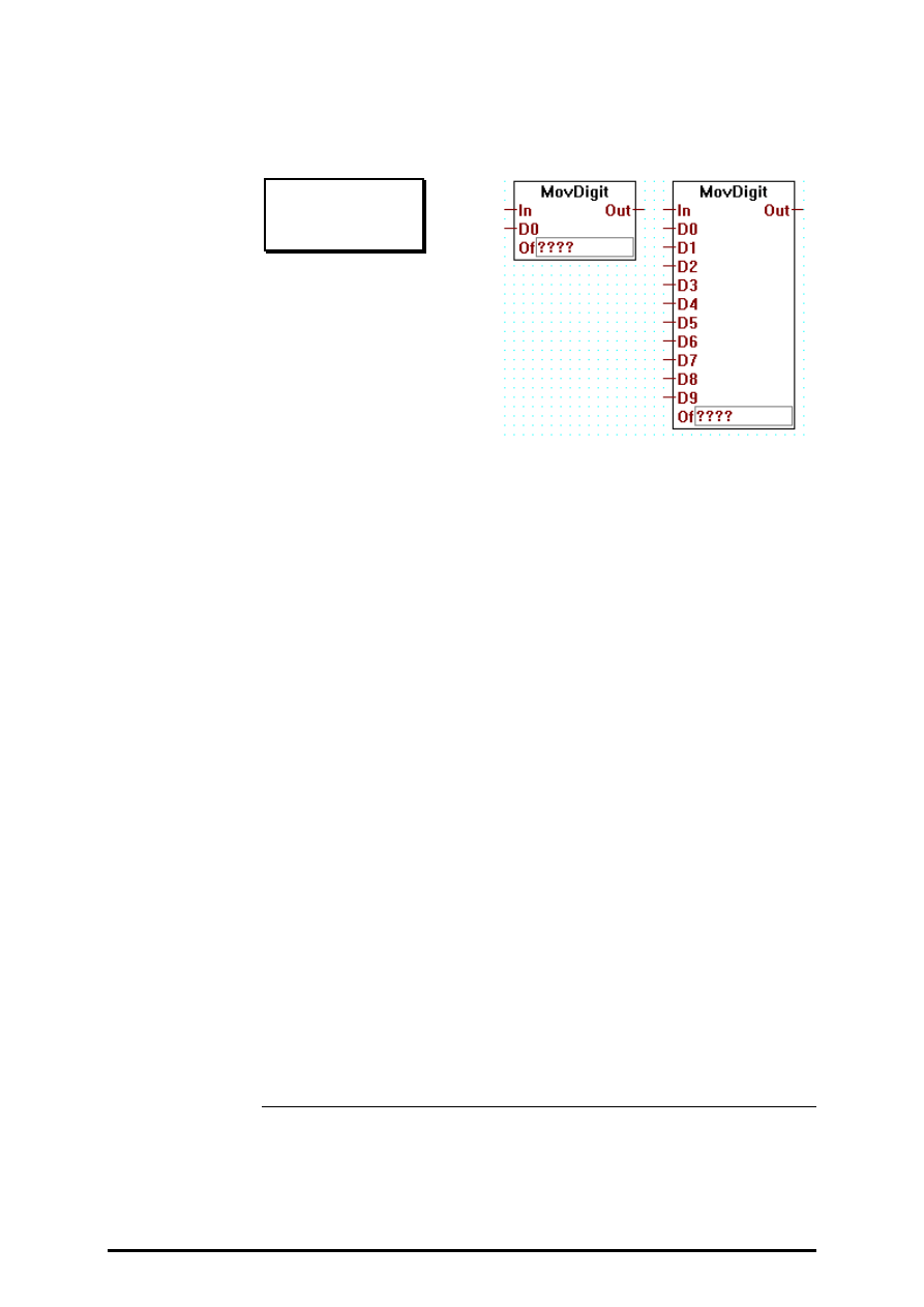
FUPLA and KOPLA functions
Move Data
26/749 E1
(P-4410-E.DOC)
SAIA AG
Page 4-111
4.4.10.5
Move-In Digit (4 Bit BCD)
Move-In Digit
[_movedigi]
Inputs:
= In:
integer format
= D0: integer format (0 - 9)
¦
= D9: integer format
= Of: Offset, integer format (0 - 9)
Output:
= Out: integer format
Move 1 to 10 digits in a register.
The input In is combined with the digit from inputs D0 to D.. (last used).
The LS-digit from D0 is moved to the digit location defined by the offset
value Of.
The next digits used are moved in the successive locations.
All other digits are not changed. The result is copied to the output Out.
E.g. "Move-In Digit" with "Of" = 3 and inputs D0 to D2:
D2 D1 D0
x x x
↓
↓
↓
o o o o x x x o o o
Digit 9 8 7 6 5 4 3 2 1 0
Only positive values can be treated.
The max. value for digit 9 is 2
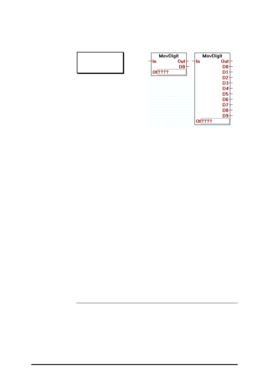
Move Data
FUPLA and KOPLA functions
Page 4-112
SAIA AG
(P4410-E.DOC)
26/749 E1
4.4.10.6
Move-Out Digit (4 Bit BCD)
Move-Out Digit
[_movedigo]
Inputs:
= In:
integer format
= Of: Offset, integer format (0 - 9)
Outputs:
= Out: integer format
= D0: integer format (0 - 9)
¦
= D9: integer format
Digits are moved out from the value of the input In. The first digit D0 is
moved from the location defined by the offset value Of.
The next digits used are moved from successive locations.
The input In is unchanged and copied to the output Out.
E.g. "Move-Out Digit", "Of" = 3 and outputs D0 to D2:
Digit 9 8 7 6 5 4 3 2 1 0
o o o o x x x o o o
↓
↓
↓
x x x
D2 D1 D0
Only positive values can be treated.
The max. value for digit 9 is 2

FUPLA and KOPLA functions
Move Data
26/749 E1
(P-4410-E.DOC)
SAIA AG
Page 4-113
4.4.10.7
Move-In Byte (8 Bit)
Move-In Byte
[_movebyti]
Inputs:
= In:
integer format
= B0: integer format (0 - 255)
¦
= B3: integer format
= Of: Offset, integer format (0 - 3)
Outputs:
= Out: integer format
Move 1 to 4 bytes in a register.
The input In is combined with the bytes from inputs B0 to B.. (last used).
The LS-byte from B0 is moved to the byte location defined by the offset
value Of.
The next bytes used are moved in the successive locations.
All other bytes are not changed. The result is copied to the output Out.
E.g. "Move-In Byte" with "Of" = 1 and inputs B0 and B1:
B 1 B 0
xxxx xxxx xxxx xxxx
↓↓↓↓
↓↓↓↓
↓↓↓↓
↓↓↓↓
oooo oooo xxxx xxxx xxxx xxxx oooo oooo
Byte 3 Byte 2 Byte 1 Byte 0

Move Data
FUPLA and KOPLA functions
Page 4-114
SAIA AG
(P4410-E.DOC)
26/749 E1
4.4.10.8
Move-Out Byte (8 Bit)
Move-Out Byte
[_movebyto]
Inputs:
= In:
integer format
= Of: Offset, integer format (0 - 3)
Outputs:
= Out: integer format
= B0: integer format (0 - 255)
¦
= B3: integer format (0 - 255)
Bits are moved out from the value of the input In. The first bit B0 is
moved from the location defined by the offset value Of.
The next bits used are moved from successive locations.
The input In is unchanged and copied to the output Out.
E.g. "Move-Out Byte", "Of" = 1 and outputs B0 and B1:
Byte 3 Byte 2 Byte 1 Byte 0
oooo oooo xxxx xxxx xxxx xxxx oooo oooo
↓↓↓↓
↓↓↓↓
↓↓↓↓
↓↓↓↓
xxxx xxxx xxxx xxxx
B 1 B 0

FUPLA and KOPLA functions
Move Data
26/749 E1
(P-4410-E.DOC)
SAIA AG
Page 4-115
4.4.10.9
Move-In Word (16 Bit)
Move-In Word
[_movewori]
Inputs:
= In:
integer format
= W0: integer format (0 - 65535)
¦
= W1: integer format
= Of: Offset, integer format (0 - 1)
Outputs:
= Out: integer format
Move 1 to 2 words in a register.
The input In is combined with the words (16 bits) from inputs W0 to W..
(last used). The LS-word from W0 is moved to the word location defined
by the offset value Of.
The next words used are moved in the successive locations.
All other words are not changed. The result is copied to the output Out.
E.g. "Move-In Word" with "Of" = 1 and input W (0):
Input W (0)
xxxx xxxx xxxx xxxx
↓↓↓↓
↓↓↓↓
↓↓↓↓
↓↓↓↓
xxxx xxxx xxxx xxxx oooo oooo oooo oooo
W 1 W 0

Move Data
FUPLA and KOPLA functions
Page 4-116
SAIA AG
(P4410-E.DOC)
26/749 E1
4.4.10.10
Move-Out Word (16 Bit)
Move-Out Word
[_moveworo]
Inputs:
= In:
integer format
= Of: Offset, integer format (0 - 1)
Outputs:
= Out: integer format
= W0: integer format (0 - 65535)
¦
= W1: integer format
Words are moved out from the value of the input In. The first word W0 is
moved from the location defined by the offset value Of.
The next words used are moved from successive locations.
The input In is unchanged and copied to the output Out.
E.g. "Move-Out Word", "Of" = 1 and output W0:
W 1 W 0
xxxx xxxx xxxx xxxx oooo oooo oooo oooo
↓↓↓↓
↓↓↓↓
↓↓↓↓
↓↓↓↓
xxxx xxxx xxxx xxxx
Output W0
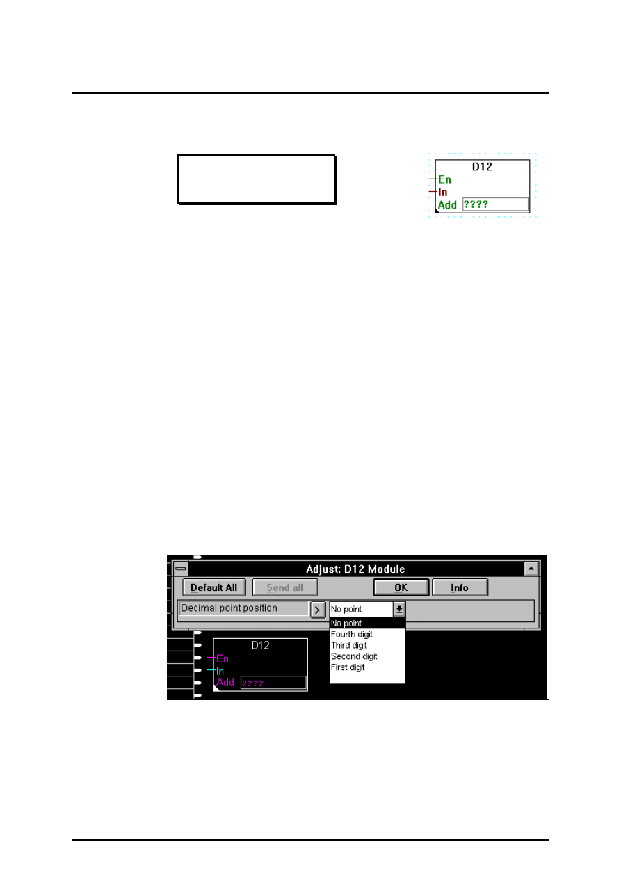
FUPLA and KOPLA functions
Displays
26/749 E1
(P-4411-E.DOC)
SAIA AG
Page 4-117
4.4.11
Displays
[sfupdisp]
4.4.11.1
Display module PCA2.D12
D12 Module
[_dispd12]
Inputs:
−
En: Enable
= In:
Integer value
Outputs one integer value to a PCA2.D12 display module.
When the function box is enabled, the 4 least significant digits of the inte-
ger are shown on the display
The D12 is enabled with the En input. The Add input contains the base
address of the D12 module. This function box assumes that Clk, D-IN and
En of the D12 module are connected to outputs Add+0, Add+1 and
Add+2 respectively.
The display remains unchanged if the function box is not enabled.
A decimal point can be adjusted manually inside the function box. In order
to do so the user must double click on the function box when he is in se-
lection mode. This parameter will be effective only after a recompilation
of the program.

Displays
FUPLA and KOPLA functions
Page 4-118
SAIA AG
(P-4411-E.DOC)
26/749 E1
4.4.11.2
Display module PCA2.D14
D14 Module
[_dispd14]
Inputs:
−
En: Enable
= Upr: Upper display - Integer value
= Lwr: Lower display - Integer value
Outputs two integer values to a PCA2.D14 display module.
When the function box is enabled, the 6 least significant digits of the Upr
integer are shown in the upper display, and the 6 least significant digits of
the Lwr integer are shown in the lower display.
The D14 is enabled with the En input. The Add input contains the base
address of the D14 module. This function box assumes that Clk, D-IN and
En of the D14 module are connected to outputs Add+0, Add+1 and
Add+2 respectively.
The display remains unchanged if the function box is not enabled.
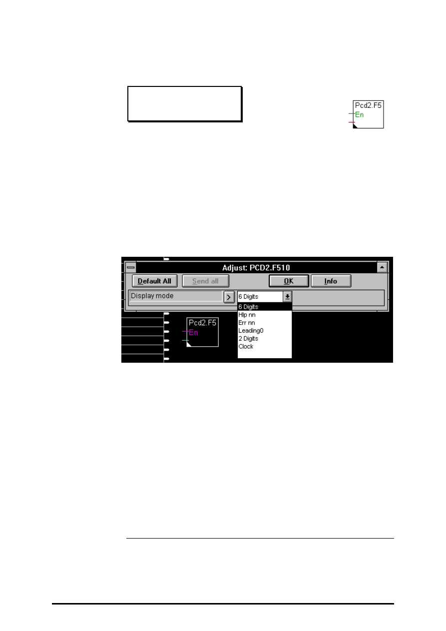
FUPLA and KOPLA functions
Displays
26/749 E1
(P-4411-E.DOC)
SAIA AG
Page 4-119
4.4.11.3
Display module PCD2.F510 for numeric displays
PCD2.F510
[_disppcd23]
Input:
−
Enable
Outputs to the PCD2.F5 display module in numeric format. PCD2.F5 can
display up to 6 digits (-99999..999999).
It can also display predefined numeric expressions. The display format is
selected in the adjust window. If input Enable is Low, the last defined
format is valid. The default format is "6 Digits"
The different selection modes are:
Selection:
what is displayed:
•
6 Digits
6 digits from Val. If Val is not between -99999 and
999999 the display is cleared.
•
Hlp nn
'HLP' with 2 digits from Val
•
Err nn
'Err' with 2 digits from Val.
If val is not between 0-99 the display is cleared.
•
Leading 0
6 digits with leading zero
•
2 Digits
2 digits mode.
If val is not between 0-99 the display is cleared.
•
Clock
Display the Val using a clock format.
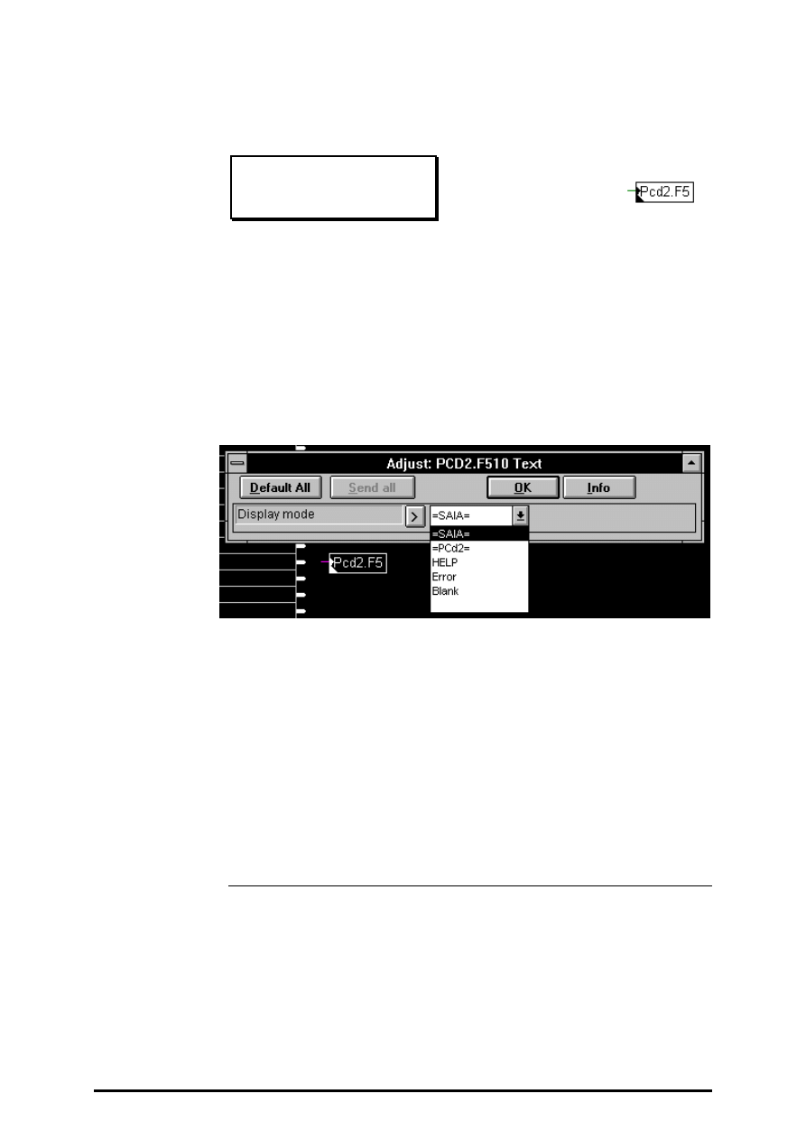
Displays
FUPLA and KOPLA functions
Page 4-120
SAIA AG
(P-4411-E.DOC)
26/749 E1
4.4.11.4
Display module PCD2.F510 for text displays
PCD2.F510 Text
[_disppcd24]
Input:
−
Enable
Outputs to the PCD2.F5 display module in text format.
It can also display predefined texts. The display format is selected in the
adjust window. If input Enable is Low, the last defined format is valid.
The default format is "=SAIA=".
The different selection modes are:
Selection:
what is displayed:
•
=SAIA=
'=SAIA='
•
=PCd2=
'PCd2='
•
HELP
' HELP '
•
Error
' Error'
•
Blank
The display will be cleared.

FUPLA and KOPLA functions
GRAFTEC functions
26/749 E1
(P-4412-E.DOC)
SAIA AG
Page 4-121
4.4.12
GRAFTEC functions
[sfupgraf]
4.4.12.1
Load timer
Load timer
[_grafldt]
Input:
= Load value: register or constant (integer format)
Fbox for loading and activating (starting) a timer in a step.
The entry field should be completed either with a symbol name or the ab-
solute timer address. (Symbol names are preferable, as symbol manage-
ment is carried out automatically).
The value to be loaded should be entered at the numeric input.
For ONLINE viewing of timer content, the symbol name or absolute
timer address should be entered in an entry field on the left-hand margin
of the FUPLA screen. In ONLINE operation, it is possible to insert an
online probe (online box) at this entry field.

GRAFTEC functions
FUPLA and KOPLA functions
Page 4-122
SAIA AG
(P-4412-E.DOC)
26/749 E1
4.4.12.2
Load timer conditional
Load timer conditional
[_grafcldt]
Inputs:
−
Cnd: Condition H/L, (binary format)
= Val: Load value: register or constant (integer format)
Fbox for conditional loading and activating (starting) a timer in a step.
The entry field should be completed either with a symbol name or the ab-
solute timer address. (Symbol names are preferable, as symbol manage-
ment is carried out automatically).
The value to be loaded should be entered at the numeric input.
Loading only takes place when the condition on the binary input "Cnd" is
met.
For ONLINE viewing of timer content, the symbol name or absolute
timer address should be entered in an entry field on the left-hand margin
of the FUPLA screen. In ONLINE operation, it is possible to insert an
online probe (online box) at this entry field.
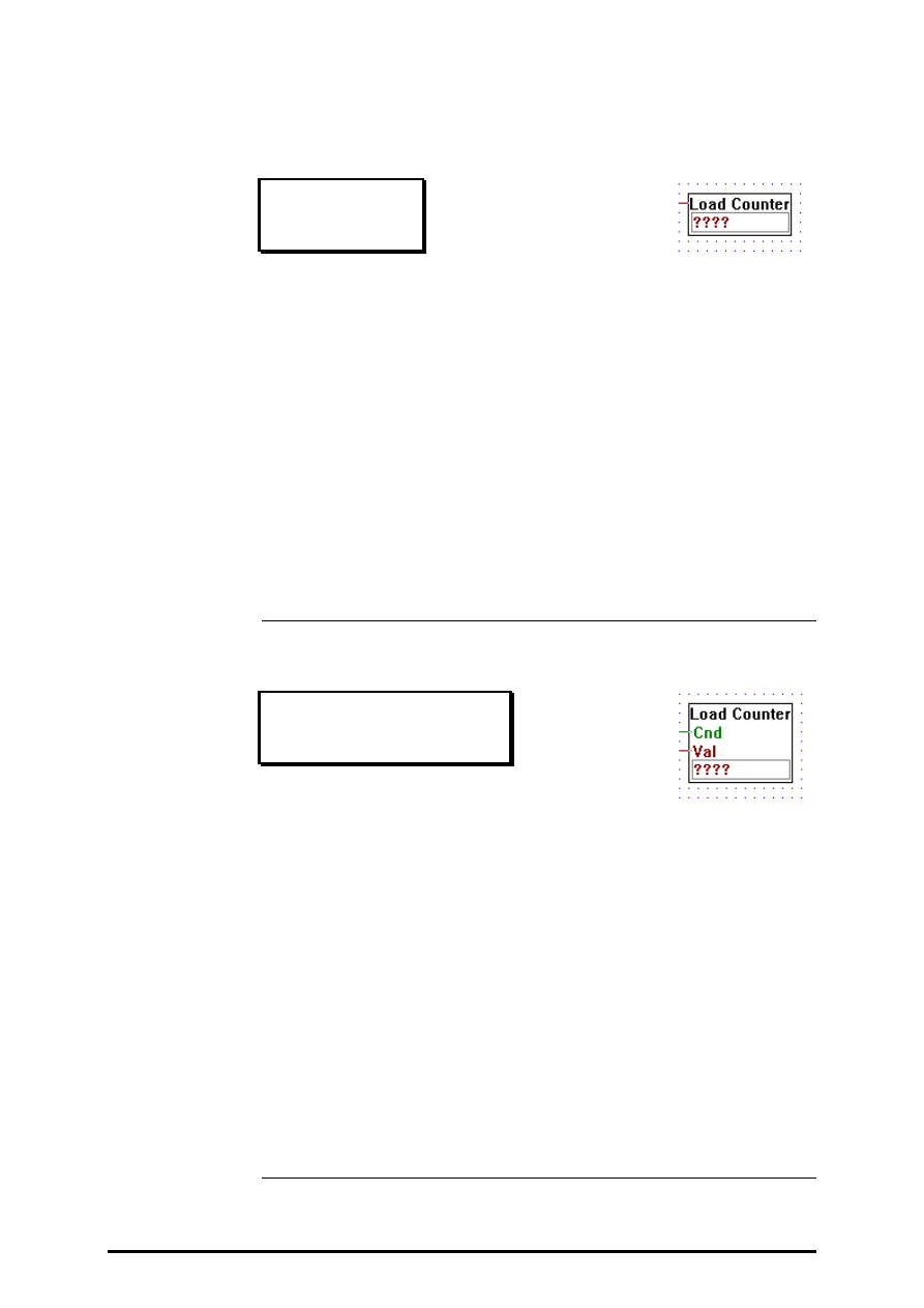
FUPLA and KOPLA functions
GRAFTEC functions
26/749 E1
(P-4412-E.DOC)
SAIA AG
Page 4-123
4.4.12.3
Load counter
Load counter
[_grafldc]
Input:
= Load value: register or constant (integer format)
Fbox for loading a counter in a step.
The entry field should be completed either with a symbol name or the ab-
solute counter address. (Symbol names are preferable, as symbol man-
agement is carried out automatically).
The value to be loaded should be entered at the numeric input.
For ONLINE viewing of counter content, the symbol name or absolute
counter address should be entered in an entry field on the left-hand margin
of the FUPLA screen. In ONLINE operation, it is possible to insert an
online probe (online box) at this entry field.
4.4.12.4
Load counter conditional
Load counter conditional
[_grafcldc]
Inputs:
−
Cnd: Condition H/L, (binary format)
= Val Load value: register or constant (integer format)
Fbox for conditional loading a counter in a step.
The entry field should be completed either with a symbol name or the ab-
solute counter address. (Symbol names are preferable, as symbol man-
agement is carried out automatically).
The value to be loaded should be entered at the numeric input. Loading
only takes place when the condition on the binary input "Cnd" is met.
For ONLINE viewing of counter content, the symbol name or absolute
counter address should be entered in an entry field on the left-hand margin
of the FUPLA screen. In ONLINE operation, it is possible to insert an
online probe (online box) at this entry field.

GRAFTEC functions
FUPLA and KOPLA functions
Page 4-124
SAIA AG
(P-4412-E.DOC)
26/749 E1
4.4.12.5
Increment counter
Increment counter
[_grafincc]
Input:
−
Condition for increment H/L (binary format)
Output:
−
logical state of the counter H/L (binary format)
Fbox for incrementing a counter (+1), normally in a step.
The counter must first have been loaded using the function “Load
Counter”.
The corresponding name or counter address from the “Load Counter” in-
struction should be indicated in the entry field.
Incrementating only takes place when the input condition is met.
For ONLINE viewing of counter content, the symbol name or absolute
counter address should be entered in an entry field on the left-hand margin
of the FUPLA screen. In ONLINE operation, it is possible to insert an
online probe (online box) at this entry field.

FUPLA and KOPLA functions
GRAFTEC functions
26/749 E1
(P-4412-E.DOC)
SAIA AG
Page 4-125
4.4.12.6
Decrement counter
Decrement counter
[_grafdecc]
Input:
−
Condition for decrement H/L (binary format)
Output:
−
logical state of the counter H/L (binary format)
Fbox for decrementing a counter (-1), normally in one step.
The counter must first have been loaded using the function “Load
Counter”.
The corresponding name or counter address from the “Load Counter” in-
struction should be indicated in the entry field.
Decrementing only takes place when the input condition is met.
For ONLINE viewing of counter content, the symbol name or absolute
counter address should be entered in an entry field on the left-hand margin
of the FUPLA screen. In ONLINE operation, it is possible to insert an
online probe (online box) at this entry field.
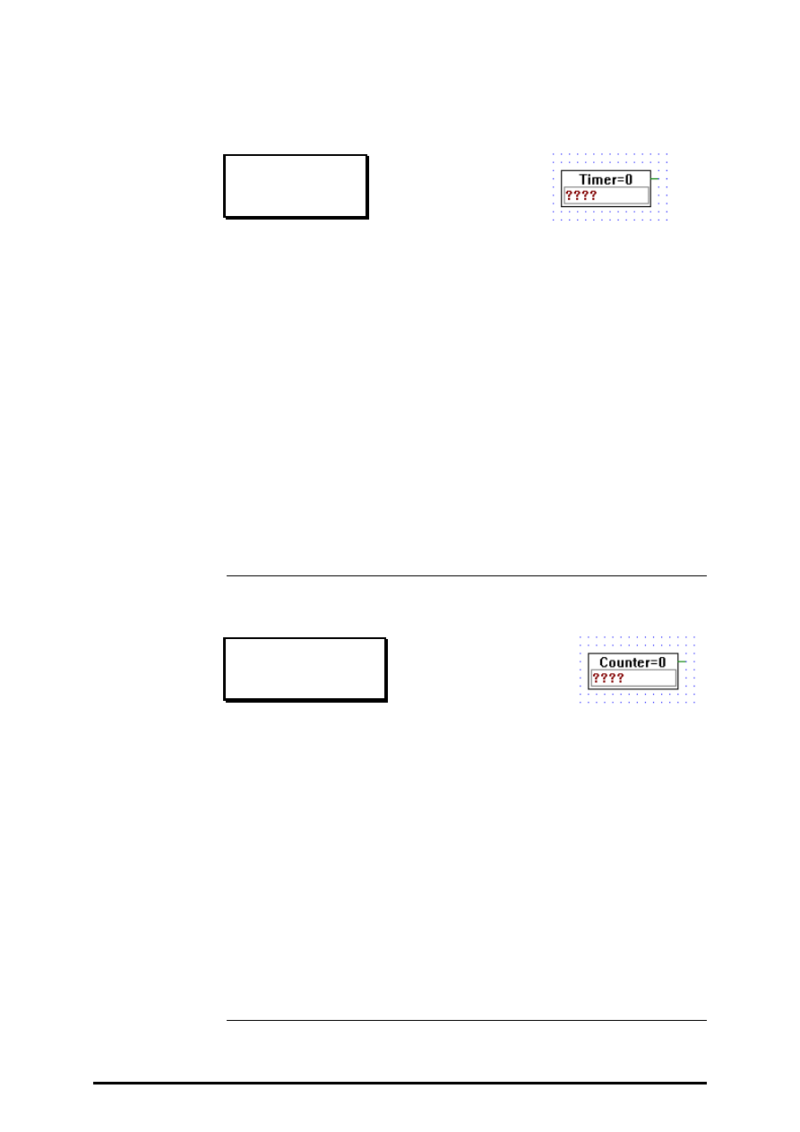
GRAFTEC functions
FUPLA and KOPLA functions
Page 4-126
SAIA AG
(P-4412-E.DOC)
26/749 E1
4.4.12.7
Timer is zero
Timer is zero
[_graftisl]
Output:
−
H if timer is 0. (binary format)
Fbox for querying the logical state of a timer in a TRANSITION. The
function is true if the timer has reached zero. If this FBox stands alone in
a TRANSITION, the next step switches in after the timer has reached
zero.
This function is linkable, preferably with Kontaktplan symbols.
The corresponding name or timer address from the “Load Timer” instruc-
tion should be indicated in the entry field.
For ONLINE viewing of timer content, the symbol name or absolute
timer address should be entered in an entry field on the left-hand margin
of the FUPLA screen. In ONLINE operation, it is possible to insert an
online probe (online box) at this entry field.
4.4.12.8
Counter is zero
Counter is zero
[_grafcisl]
Output:
−
H if timer is 0. (binary format)
Fbox for querying the logical state of a counter in a TRANSITION. The
function is true if the counter has reached zero.
This function is linkable, preferably with Kontaktplan symbols.
The corresponding name or counter address from the “Load Timer” in-
struction should be indicated in the entry field.
For ONLINE viewing of counter content, the symbol name or absolute
counter address should be entered in an entry field on the left-hand margin
of the FUPLA screen. In ONLINE operation, it is possible to insert an
online probe (online box) at this entry field.
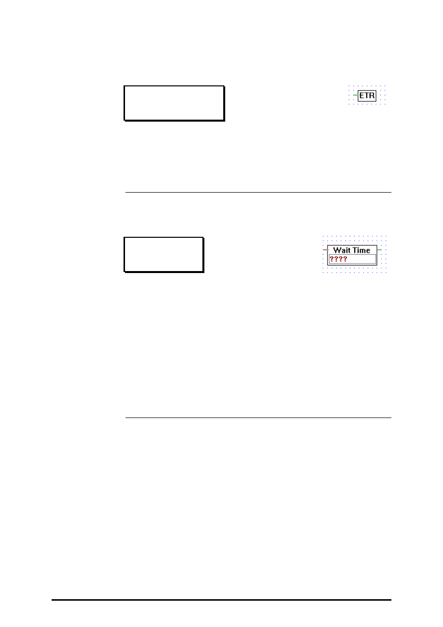
FUPLA and KOPLA functions
GRAFTEC functions
26/749 E1
(P-4412-E.DOC)
SAIA AG
Page 4-127
4.4.12.9
End of transition
End of transition
[_grafetrsv]
Input:
−
binary format
This fbox is used in a transition. When its input is high it indicates that the
transition is completed else it is not.
4.4.12.10
Wait Time
Wait Time
[_grafwait]
Input:
= Time value: register or constant (integer format)
Output:
−
H if timer is 0. (binary format)
Compact Fbox to program a wait pause in a TRANSITION. The first
time the TRANSITION is exectuted, the timer is started with the value at
the input. The output is true if the timer has reached zero.
For ONLINE viewing of timer content, the symbol name or absolute
timer address should be entered in an entry field on the left-hand margin
of the FUPLA screen. In ONLINE operation, it is possible to insert an
online probe (online box) at this entry field.

GRAFTEC functions
FUPLA and KOPLA functions
Page 4-128
SAIA AG
(P-4412-E.DOC)
26/749 E1
4.4.12.11
Waite Pulse
Waite Pulse
[_grafwpls]
Input:
−
Dec: Decrement (binary format)
= Nb: Load value:
register or constant (integer format)
Output:
−
H if counter is 0. (binary format)
Compact Fbox to program a pause waiting pulses in a TRANSITION.
The first time the TRANSITION is exectuted, the counter is started with
the value at the input. Each pulse at the input Dec will decrement the
counter by one. The output is true if the counter has reached zero.
For ONLINE viewing of counter content, the symbol name or absolute
counter address should be entered in an entry field on the left-hand margin
of the FUPLA screen. In ONLINE operation, it is possible to insert an
online probe (online box) at this entry field.
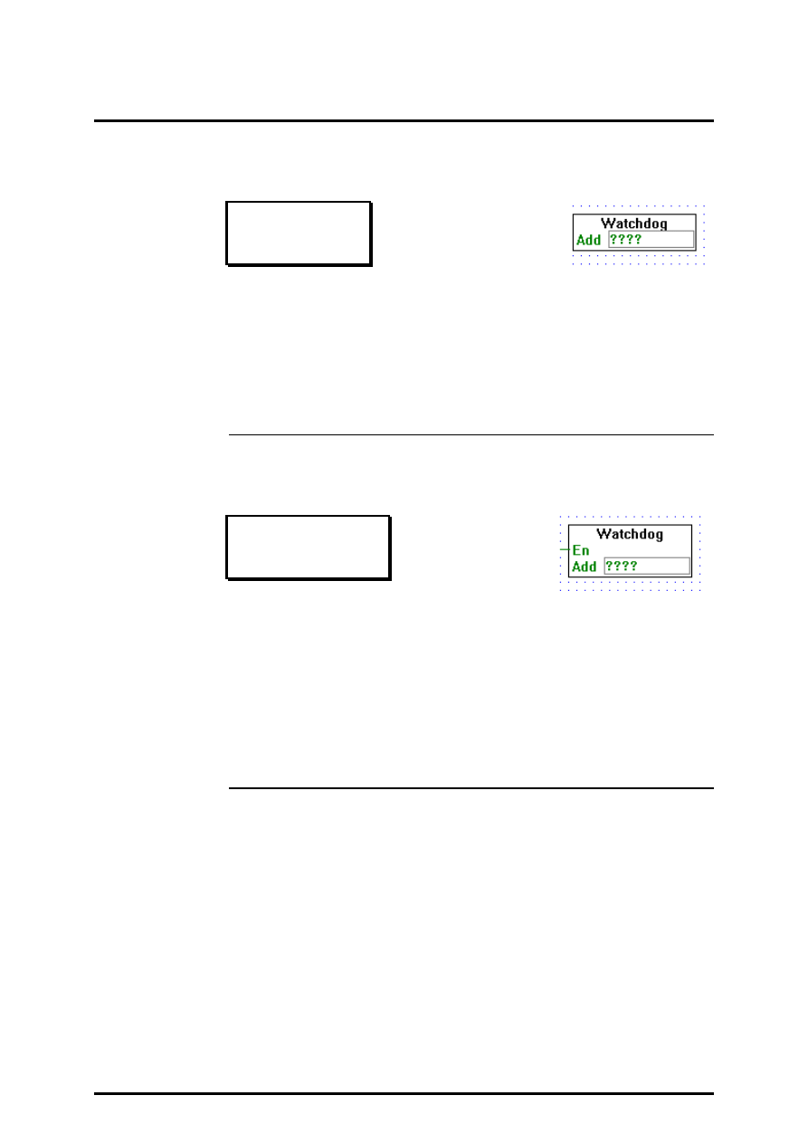
FUPLA and KOPLA functions
Special functions
26/749 E1
(P-4413-E.DOC)
SAIA AG
Page 4-129
4.4.13
Special functions
[sfupspec]
4.4.13.1
Watch dog
Watch dog
[_watchdog]
When this function box is called at a frequency
≥
5Hz it keeps the watch-
dog circuit active.
The element address "Add" is normally 255. (See hardware manuals
PCD2, PCD4, PCD6).
4.4.13.2
Watch dog with enable
Watch dog enable
[_watchdoge]
Input:
−
En
Enable (binary format)
When this function box is called with its entry En (enable) at a frequency
≥
5Hz it keeps the watchdog circuit active.
The element address "Add" is normally 255. (See hardware manuals
PCD2, PCD4, PCD6).

FUPLA and KOPLA functions
Analog modules
26/749 E1
(P-4414-E.DOC)
SAIA AG
Page 4-131
4.4.14
Analog modules
[sfupanlg]
4.4.14.1
Analog Input module PCD2.W1 (12 bit)
PCD2.W1
[_anad2w1]
Inputs: = i0
¦
: Integer values
= i3
This function box outputs the A/D conversion of the PCD2.W1 analogic
input card.
Each time this function box is executed one input channel is converted.
When the conversion of a channel is not ready this function box outputs
its last valid conversion. If a channel has never been converted since the
system initialisation, it will output 0.
One function box PCD2.W1 must be used for each PCD2.W1 card used.
The parameter Add is the base address of the card. E.g.: O 16. Output
240 must never be used for analogic module.
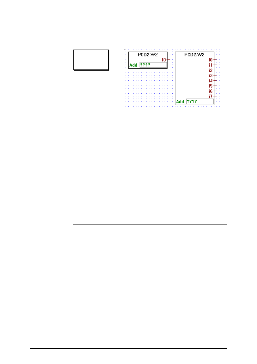
Analog modules
FUPLA and KOPLA functions
Page 4-132
SAIA AG
(P-4414-E.DOC)
26/749 E1
4.4.14.2
Analog Input module PCD2.W2 (8 Bit)
PCD2.W2
[_anad2w2]
Inputs: = i0
¦
Integer values
= i7
This function box outputs the A/D conversion of the PCD2.W2 analogic
input card.
Each time this function box is executed one input channel is converted.
When the conversion of a channel is not ready this function box outputs
its last valid conversion. If a channel has never been converted since the
system initialisation, it will output 0.
One function box PCD2.W2 must be used for each PCD2.W2 card used.
The parameter Add is the base address of the card. E.g.: O 16. Output
240 must never be used for analogic module.
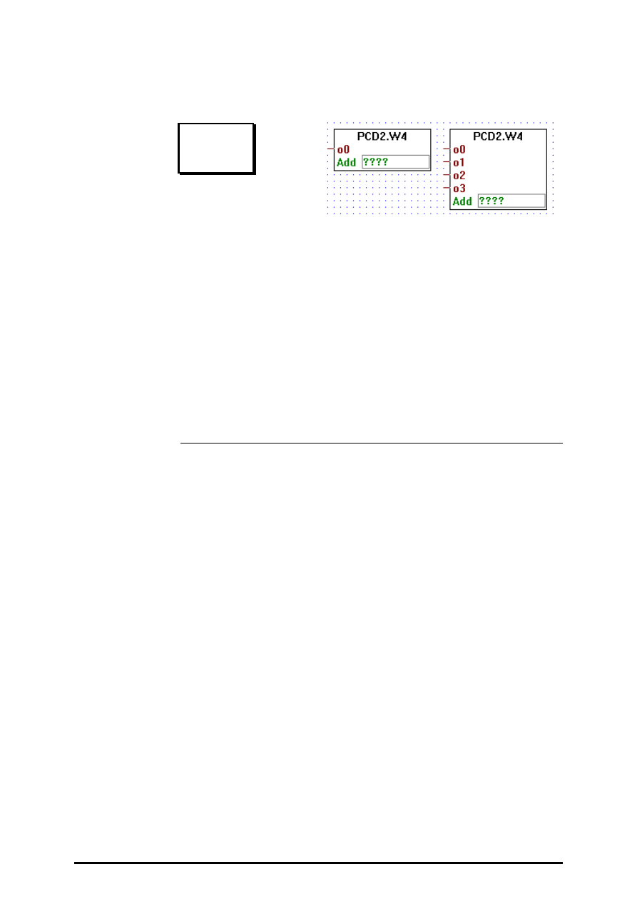
FUPLA and KOPLA functions
Analog modules
26/749 E1
(P-4414-E.DOC)
SAIA AG
Page 4-133
4.4.14.3
Analog Output module PCD2.W4 (8 Bit)
PCD2.W4
[ _anad2w4
]
Outputs:= o0
¦
Integer values
= o3
This function box transfers its (1 to 4) inputs to the outputs of a
PCD2.W4 D/A converter module.
One function box PCD2.W4 must be used for each PCD2.W4 card used.
The parameter Add is the base address of the card. E.g.: O 16. Output
240 must never be used for analogic module.

Analog modules
FUPLA and KOPLA functions
Page 4-134
SAIA AG
(P-4414-E.DOC)
26/749 E1
4.4.14.4
Analog Input/Output module PCD2.W5 (12 Bit)
PCD2.W5
[_anad2w5
]
Inputs:
= i0
integer value
= i1
integer value
Outputs:
= o0
integer value
= o1
integer value
This function box outputs the A/D conversion of the input channels of the
PCD2.W5 analogic card, and transfers its inputs to the D/A outputs of the
same module. It has 2 inputs which are related to output o0 and o1 of the
PCD2.W5, and it has 2 outputs which are associated to input i0 and i1 of
the PCD.W5.
Each time this function box is executed one input channel is converted.
When the conversion of an input channel is not ready its last valid conver-
sion is output. If a channel has never been converted since the system ini-
tialisation, it will output 0.
One function box PCD2.W5 must be used for each PCD2.W5 card used.
The parameter Add is the base address of the card. E.g.: O 16. Output
240 must never be used for analogic module (conflict with the watchdog).
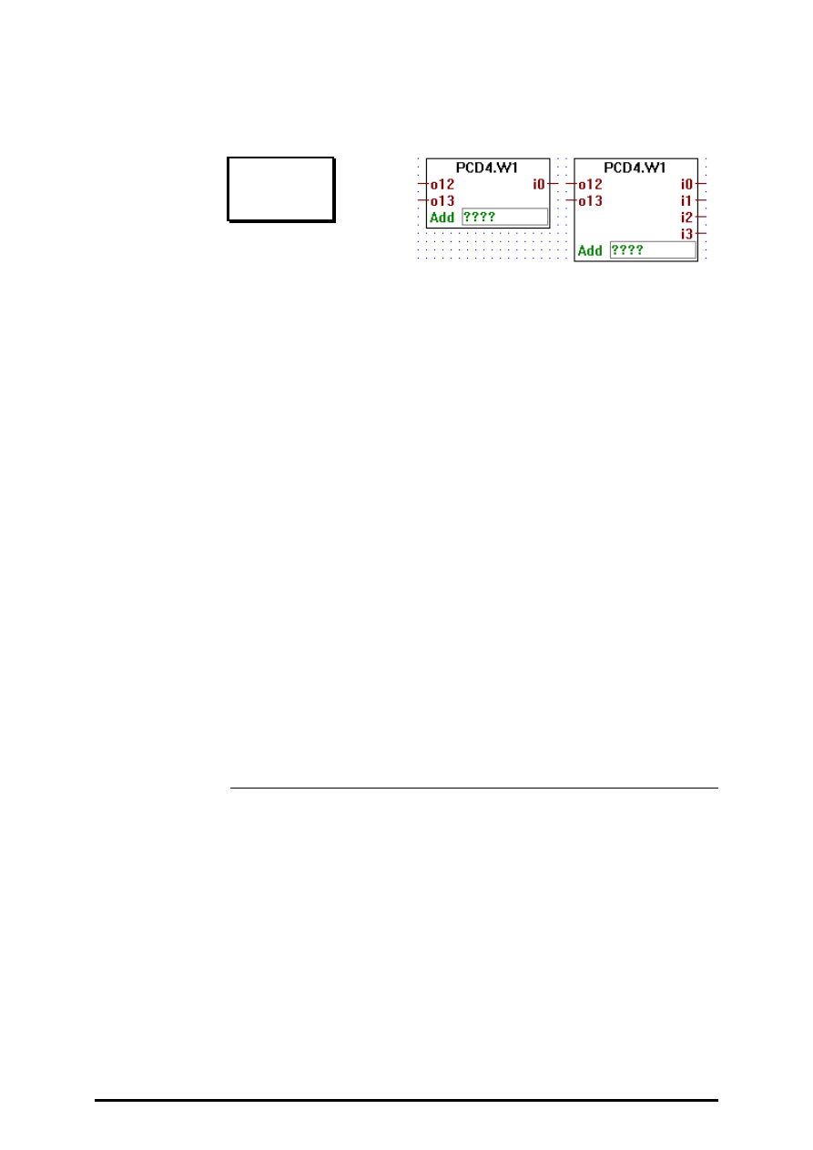
FUPLA and KOPLA functions
Analog modules
26/749 E1
(P-4414-E.DOC)
SAIA AG
Page 4-135
4.4.14.5
Analog Input/Output module PCD4.W1 (12 Bit)
PCD4.W1
[_anad4w1 ]
Inputs: = i0
¦
Integer values
= i3
Outputs = 012
¦
Integer values
= 013
This function box outputs the A/D conversion of the input channels of the
PCD4.W1 analogic card, and transfers its inputs to the D/A outputs of the
same module. It has 2 inputs o12 and o13 which are related to output 12
and 13 of the PCD4.W1, and it has up to 4 outputs labeled i0 to i3 which
are associated to input 0 to 3 of the PCD4.W1.
Each time this function box is executed one input channel is converted.
When the conversion of an input channel is not ready its last valid conver-
sion is output. If a channel has never been converted since the system ini-
tialisation, it will output 0.
One function box PCD4.W1 must be used for each PCD4.W1 card used.
The parameter Add is the base address of the card. E.g.: O 16. Output
240 and output 496 must never be used for analogic module.

Analog modules
FUPLA and KOPLA functions
Page 4-136
SAIA AG
(P-4414-E.DOC)
26/749 E1
4.4.14.6
Analog Input module PCD4.W3 ( 12 Bit + Sign )
PCD4.W3
[_anad4w3]
Inputs: = i0
¦
Integer values
= i7
This function box outputs the A/D conversion of the input channels of a
PCID4.W3 analogic card. It has up to 8 outputs labeled i0 to i7 which are
associated to input 0 to 7 of a PCD4.W3 analogic input card.
Each time this function box is executed one input channel is converted.
When the conversion of an input channel is not ready its last valid conver-
sion is output. If a channel has never been converted since the system ini-
tialisation, it will output 0.
One function box PCD4.W3 must be used for each PCD4.W3 card used.
The parameter Add is the base address of the card. E.g.: O 16. Output
240 and output 496 must never be used for analogic module.
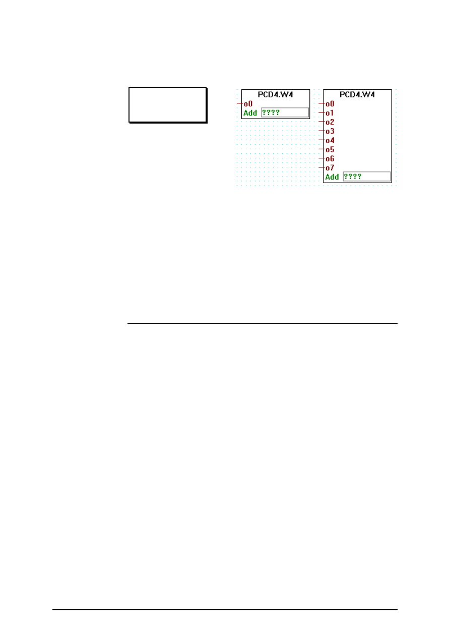
FUPLA and KOPLA functions
Analog modules
26/749 E1
(P-4414-E.DOC)
SAIA AG
Page 4-137
4.4.14.7
Analog Output module PCD4.W4 ( 8 Bit )
PCD4.W4
[_anad4w4]
Outputs:= o0
¦
Integer values
= o7
This function box transfers its 1 to 8 inputs to the outputs of a PCD4.W4
D/A converter module.
One function box PCD4.W4 must be used for each PCD4.W4 card used.
The parameter Add is the base address of the card. E.g.: O 16. Output
240 and Output 496 ust never be used for analogic module.
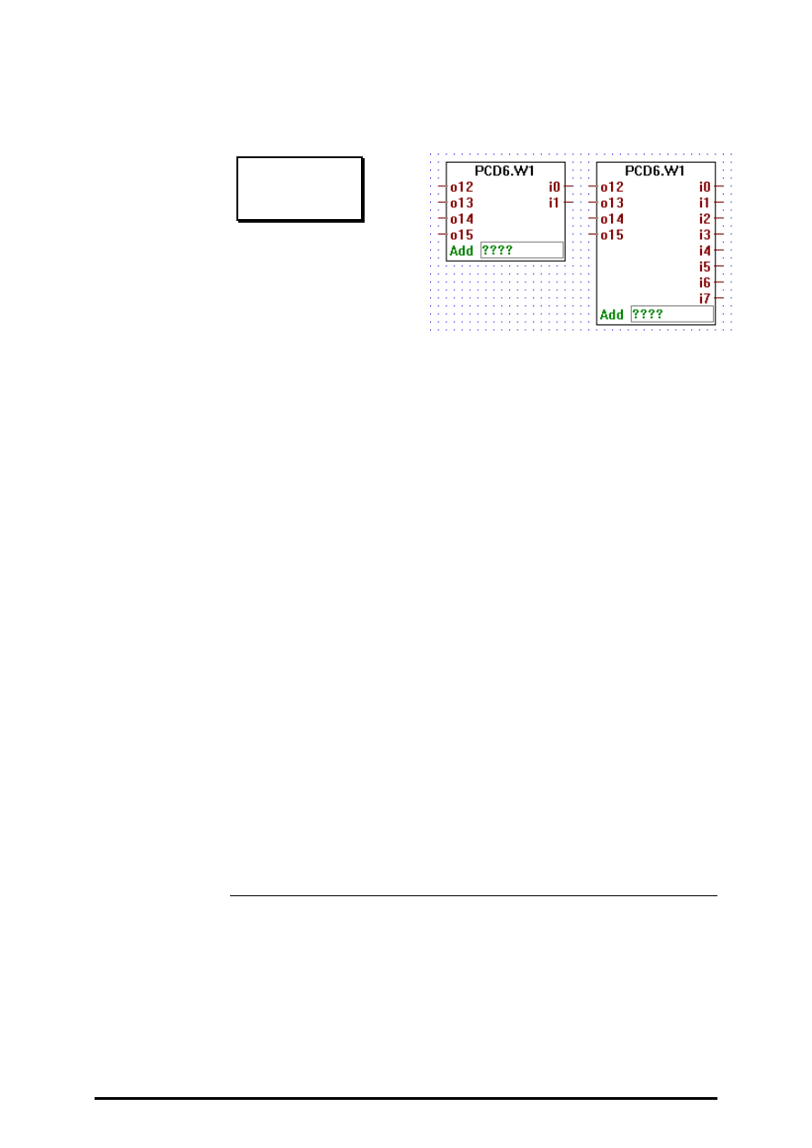
Analog modules
FUPLA and KOPLA functions
Page 4-138
SAIA AG
(P-4414-E.DOC)
26/749 E1
4.4.14.8
Analog Input / Output module PCD6.W1 ( 12 Bit )
PCD6.W1
[_anad6w1]
Outputs: = o12
¦
Integer values
= o15
Inputs: = i0
¦
Integer values
= i7
This function box outputs the A/D conversion of the input channels of a
PCD6.W1 analogic card, and transfers its inputs to the D/A outputs of the
same module. It has 4 inputs o12 to o15 which are related to output 12 to
15 of the PCD6.W1, and it has up to 8 outputs labeled i0 to i7 which are
associated to input 0 to 7 of the PCD6.W1.
Each time this function box is executed one input channel is converted.
When the conversion of an input channel is not ready its last valid conver-
sion is output. If a channel has never been converted since the system ini-
tialisation, it will output 0.
One function box PCD6.W1 must be used for each PCD6.W1 card used.
The parameter Add is the base address of the card. E.g.: O 16. The last
address available of each rack must never be used for analogic module
card, i.e.: rack base address + 240.
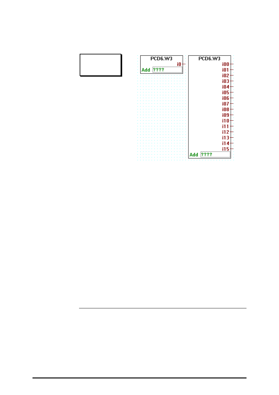
FUPLA and KOPLA functions
Analog modules
26/749 E1
(P-4414-E.DOC)
SAIA AG
Page 4-139
4.4.14.9
Analog Input module PCD6.W3 ( 12 Bit + Siggn )
PCD6.W3
[_anad6w3]
Inputs: = i00
¦
Integer values
= i15
This function box outputs the A/D conversion of the input channels of a
PCD6.W3 analogic card. It has up to 16 outputs labeled i0 to i15 which
are associated to input 0 to 15 of a PCD6.W3 analogic input card.
Each time this function box is executed one input channel is converted.
When the conversion of an input channel is not ready its last valid conver-
sion is output. If a channel has never been converted since the system ini-
tialisation, it will output 0.
One function box PCD6.W3 must be used for each PCD6.W3 card used.
The parameter Add is the base address of the card. E.g.: O 16. The last
address available of each rack must never be used for analogic module
card, i.e.: rack base address + 240.
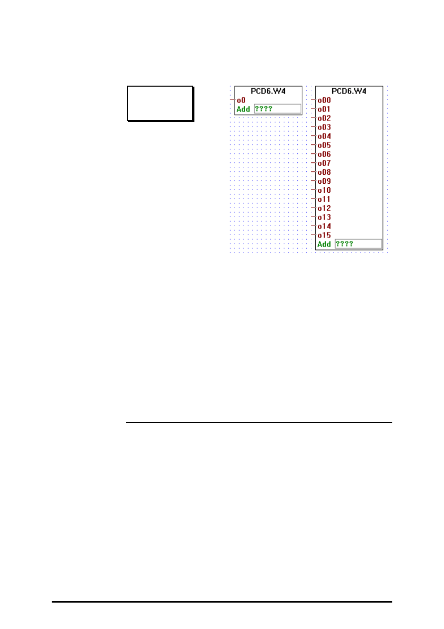
Analog modules
FUPLA and KOPLA functions
Page 4-140
SAIA AG
(P-4414-E.DOC)
26/749 E1
4.4.14.10
Analog Output module PCD6.W4 ( 8 Bit )
PCD6.W4
[_anad6w4]
Outputs:= o00
¦
Integer values
= o15
This function box transfers its 1 to 16 inputs to the outputs of a
PCD6.W4 D/A converter module.
One function box PCD6.W4 must be used for each PCD6.W4 card used.
The parameter Add is the base address of the card. E.g.: O 16. The last
address available of each rack must never be used for analogic module
card, i.e.: rack base address + 240.

FUPLA and KOPLA functions
Regulation
26/749 E1
(P-4415-E.DOC)
SAIA AG
Page 4-141
4.4.15
Regulation (PID control)
[sfupregu]
4.4.15.1
PID FBox
PID FBox
[_regpid3]
Inputs:
W:
Set Point
integer format
X:
Actual Value
integer format
YS:
Cold Start Set Point integer format
CS:
Cold Start Signal
binary format
Output:
Y:
Manipulated Value
integer format
The following description is based on the assumption that the reader has a
good knowledge of control engineering.The PID-instruction of the PCD
is explained in the manual "PCD Series Reference Guide".
Cold start and manual mode:
YS ist the set point which is used from the system program as cold start
value for Y. If the CS signal is dynamised then the regulation will con-
tinue after a cold start. If CS is high for a longer time, YS is transmitted
to Y on each sampling signal. The regulation is out of use and may be
continued in manual mode.
The following 6 parameters can be defined in the adjust window:
Sampling rate:
Defines the sampling rate at which the PID will take its sample. The units
of time used in the variable is the same as the one which was defined for
the timers. See also instruction DEFTB.
Proportional Factor P:
The factor P determine the proportional (amplification) characteristic of
the regulator. When calculating, only the lower 16 bits are used
(0..65535). The proportional factor is determined as follows:
Fp = (1/Xp)*256
with Xp: Proportional band.

Regulation
FUPLA and KOPLA functions
Page 4-142
SAIA AG
(P-4415-E.DOC)
26/749 E1
Integral Factor Fi:
This factor determines the integral characteristic of the regulator. When
calculating, only the 16 lower bits are used (0..65535). The Integral factor
is determined as follow:
Fi = (T0/Ti) * 256
with
T0: sampling time of the PID instruction
Ti: integral time.
Derivative Factor Fd:
This factor determines the derivative characteristic of the regulator. When
calculating, only the 16 lower bits are used (0..65535). The Derivative
factor is determined as follow:
Fd= (Td/T0) * 256
with
T0: sampling time of the PID instruction
Td: derivative time.
Dead Range Dr:
The dead range defines the range in which the variations of the controlled
variable may occur without causing a modification of the Manipulated
variable MV.
Cold Start Ys:
This value is used as starting value for Yn by the system program. As
soon as the user program writes a value other than 0 to the cold start reg-
ister, a cold start calculation is made and Yn is set with Ys, and the other
internal values are Note: In order to achieve a smooth transition, Ys may
be set equal to the currently used controlled variable.
Bit resolution:
The maximum of all manipulated variables are determined by the resolution.
8 bits: 0..255;
12 bits: 0..4095;
16 bits: 0..65,535
The resolution is mostly defined by the analog module used for the Result
variable output.
Adjust window:
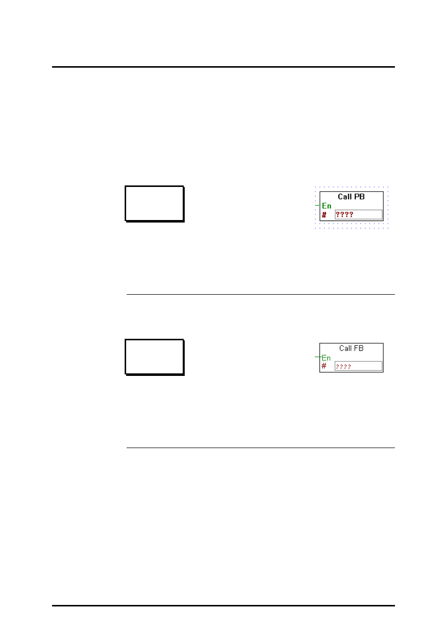
FUPLA and KOPLA functions
User defined functions
26/749 E1
(P-4416-E.DOC)
SAIA AG
Page 4-143
4.4.16
User-defined functions
[sfupuser]
A comfortable tool to program own functions is not yet available for this
version.
To edit often used program parts it is recommended to program such
parts as PB or FB in FUPLA or IL and call them conditionally or uncon-
ditionally from the FUPLA.
4.4.16.1
Call PB
Call PB
[_call_pb]
Inputs:
−
En: Enable
binary format
#
PB address
integer format
Calls the PB number # (0 - 299) when the input En is HIGH.
4.4.16.2
Call FB
Call FB
[_call_fb]
Inputs:
−
En: Enable
binary format
#
FB address
integer format
Calls the FB number # (0 - 999) when the input En is HIGH.

User defined functions
FUPLA and KOPLA functions
Page 4-144
SAIA AG
(P-4416-E.DOC)
26/749 E1
4.4.16.3
Call SB
Call SB
[_call_sb]
Inputs:
−
En: Enable
binary format
#
SB address
integer format
Calls the SB number # (0 - 31) when the input En is HIGH.
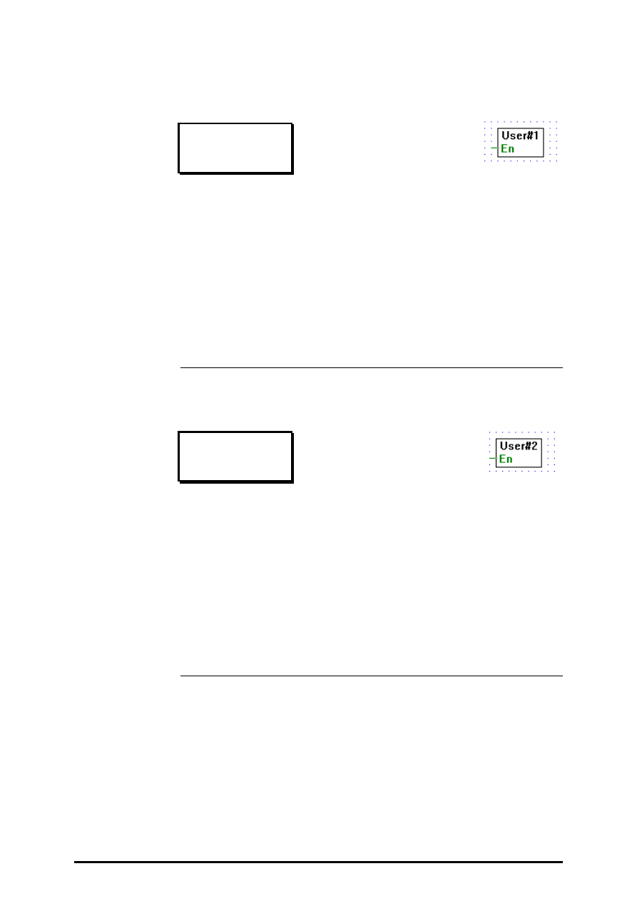
FUPLA and KOPLA functions
User defined functions
26/749 E1
(P-4416-E.DOC)
SAIA AG
Page 4-145
4.4.16.4
User block 1
User block 1
[_user_1]
Input:
−
En: Enable
binary format
Provides a way to include user code. When the binary input En (Enable) is
actived the user code is executed. The user code must be put in the in-
clude file "user_1.h".
This solution does not provide a clean way of passing parameters from the
FUPLA program to the user code, however future versions will. We
strongly suggest not to use this scheme too intensively, future version will
probably not support it.
4.4.16.5
User block 2
User block 2
[_user_2]
Input:
−
En: Enable
binary format
Provides a way to include user code. When the binary input En (Enable) is
actived the user code is executed. The user code must be put in the in-
clude file "user_2.h".
This solution does not provide a clean way of passing parameters from the
FUPLA program to the user code, however future versions will. We
strongly suggest not to use this scheme too intensively, future version will
probably not support it.

User defined functions
FUPLA and KOPLA functions
Page 4-146
SAIA AG
(P-4416-E.DOC)
26/749 E1
4.4.16.6
User block 3
User block 3
[_user_3]
Input:
−
En: Enable
binary format
Provides a way to include user code. When the binary input En (Enable) is
actived the user code is executed. The user code must be put in the in-
clude file "user_3.h".
This solution does not provide a clean way of passing parameters from the
FUPLA program to the user code, however future versions will. We
strongly suggest not to use this scheme too intensively, future version will
probably not support it.
4.4.16.7
User block 4
User block 4
[_user_4]
Input:
−
En: Enable
binary format
Provides a way to include user code. When the binary input En (Enable) is
actived the user code is executed. The user code must be put in the in-
clude file "user_4.h".
This solution does not provide a clean way of passing parameters from the
FUPLA program to the user code, however future versions will. We
strongly suggest not to use this scheme too intensively, future version will
probably not support it.

FUPLA and KOPLA functions
User defined functions
26/749 E1
(P-4416-E.DOC)
SAIA AG
Page 4-147
4.4.16.8
User block 5
User block 5
[_user_5]
Input:
−
En: Enable
binary format
Provides a way to include user code.
When the binary input En (Enable) is actived the user code is executed.
The user code must be put in the include file "user_5.h".
This solution does not provide a clean way of passing parameters from the
FUPLA program to the user code, however future versions will. We
strongly suggest not to use this scheme too intensively, future version will
probably not support it.

FUPLA and KOPLA functions
Serial communcations
26/749 E1
(P-4417-E.DOC)
SAIA AG
Page 4-149
4.4.17
Serial communications (mode "D")
[sfupcomm]
4.4.17.1
Interface parameter assignment for a serial interface
Interface parameters
[_comsasi]
Initialization of serial communications: SASI
On PCD start-up, a serial interface is assigned with the defined communi-
cations mode. Each interface utilized in a PCD must be assigned with this
function (a separate SASI function for each channel). After switching off
and on again, or after a restart cold, the channels are assigned as soon as
the PCD is switched into RUN, i.e. as soon as the restart cold routine
XOB 16 has been executed.
Parameters:
Text number: Each SASI function uses a text (no. 0...3999). Care should
be taken that the text has not already been used somewhere else in the
program, or in any of the modules which are linked.
Channel: Serial interface number 0...3. For the PCD2, PCD4 and
PCD6.M540, channel 0 is the programming unit interface (PGU). If it is
assigned with SASI, this interface no longer functions for programming.
Mode:
Mode "None" allows assignment to be disabled, without losing the func-
tion parameters.
Mode "Text" is used to execute assignment in mode C. The texts and the
user program in which these texts are used must be created with the PG3
Programming Utilities. Modes "Master" or "Slave" are not significant. As-
signment always takes place in mode MC0.
Modes D, SBUS 0 and SBUS 1 provide important advantages when used
with FUPLA, because of the "Communications" family's functions for
transmitting and receiving boolean and integer values.
With mode D (point-to-point) one station must always be assigned as
master (client) and the other as a slave (server). All transmit and receive
functions must be programmed at the master station.

Serial communcations
FUPLA and KOPLA functions
Page 4-150
SAIA AG
(P-4417-E.DOC)
26/749 E1
In S-Bus mode (multi-point connection) only one station can be assigned
as master. All others are slave stations. If the master is a control system, it
takes on the role of master. All other stations are slave stations here too.
The transmit and receive functions cannot be used by the slave stations.
For further information on communications modes, consult the PCD user
manuals.
Baud rate:
This must be the same for all stations on the bus. The baud rate is to be
selected in accordance with the quality of the bus and the potential out-
puts of the apparatus connected (PCD driver, repeater, modem, cable,
etc.).
Number of bits, parity and stop-bit:
These settings must be the same for all stations connected. In SBUS mode
these parameters are not used.
Diagnostic flag and diagnostic register:
See PCD user manuals.
The SASI online parameter ("OK" or "Error") displays whether the SASI
function was executed correctly when the PCD was switched on. If there
is an error, communication is not possible on this channel.
The following are potential sources of error:
•
the firmware does not support the mode selected (especially SBUS)
•
the CPU does not have access to this channel
•
the CPU cannot process the (high) baud rate (mainly 38,400 bps)
•
the channel has been assigned more than once (e.g. by a linked pro-
gram)
•
syntax error in the assignment text. This error should not arise with the
present software package, unless the SASI text has been modified
manually (e.g. using the debugger).
Debug:
The debug function allows the correct operation of communications to be
monitored in the master station. If communications are running, there is a
cyclical display of stations, media addressed in sequence, and diagnostic
data. To obtain better control of diagnostic data and analyse a connection
problem, communications can be interrupted with an initial click on the
"Step" button. Each subsequent click triggers the next communications
instruction (transmit or receive). With the "Run" button, communications
can be made to continue normally. The information items "Station",
"Media" and "Address" permit identification of the current transmit or re-
ceive function.
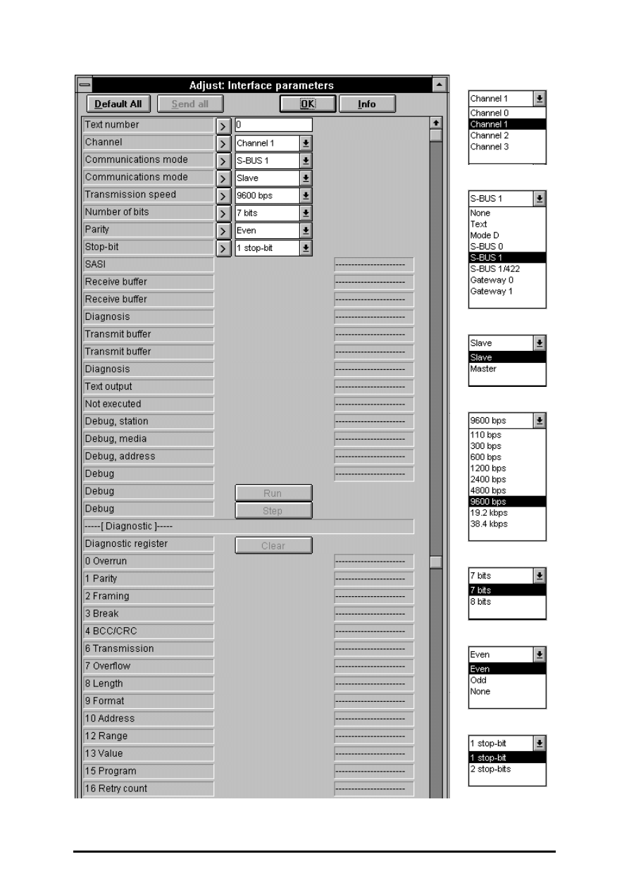
FUPLA and KOPLA functions
Serial communcations
26/749 E1
(P-4417-E.DOC)
SAIA AG
Page 4-151
Continue of the adjust window on the next page.
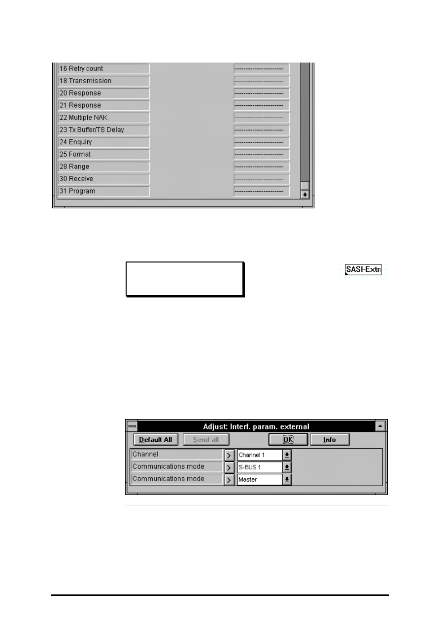
Serial communcations
FUPLA and KOPLA functions
Page 4-152
SAIA AG
(P-4417-E.DOC)
26/749 E1
4.4.17.2
Interface parameters external
Interf. param. external
[_comsase]
If two or more FUPLA files in a project access the same serial interface,
one (main) file must be used to execute "normal" assignment with the
"Interface parameters" FBox. The other file(s) should then include the
FBox shown here: "Interface parameters external", and set the same pa-
rameters as in the main file.
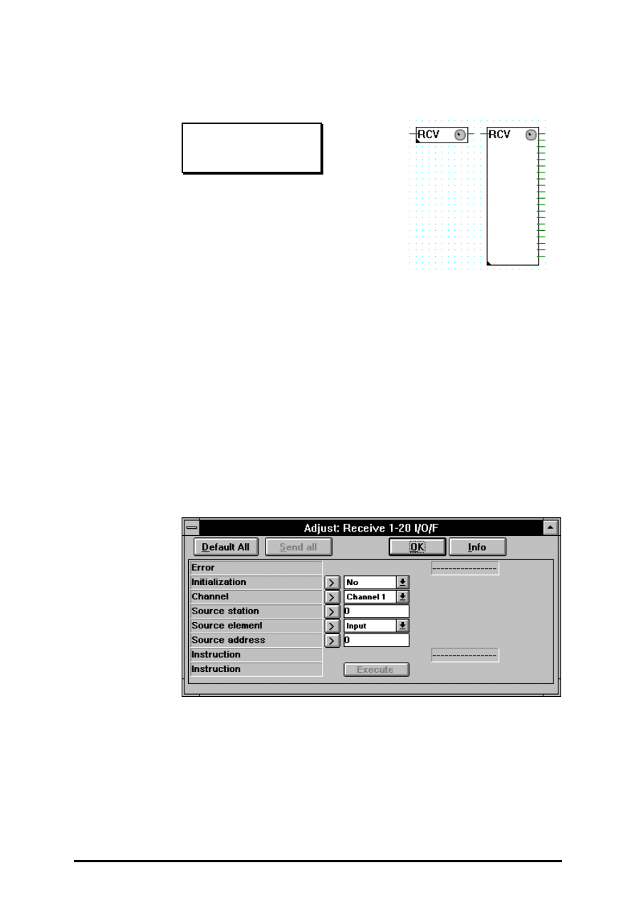
FUPLA and KOPLA functions
Serial communcations
26/749 E1
(P-4417-E.DOC)
SAIA AG
Page 4-153
4.4.17.3
Receive 1-20 Inputs/Outputs/Flags
Receive 1-20 I/O/F
[_comrxb]
Input:
−
Enable
binary format
Outputs:
−
Bit values
binary format
If the Enable input = H (binary connection to the left of the function box),
the data (boolean elements = inputs, outputs or flags) is transferred from
the partner station to boolean elements in this station. The elements in this
station are defined by the connections on the right-hand side of the func-
tion box.
The function can be extended from 1 up to 20 receive elements.
Additional settings, such as channel number, type of source element, etc.,
are made in the appropriate settings window.
Receive 1-20 I/O/F (detailed description)
This function can only be executed on a master PCD, which has been as-
signed with the SASI function in D or SBUS mode.

Serial communcations
FUPLA and KOPLA functions
Page 4-154
SAIA AG
(P-4417-E.DOC)
26/749 E1
The function permits from 1 up to 20 x boolean elements (I/O/F) to be re-
ceived from a slave station. Transmission takes place cyclically at the
maximum possible speed for as long as the active signal is high (input
"Send"). When the input receives a positive edge, at least one transmis-
sion takes place, even if the impulse is shorter than one communications
transmission cycle.
Potential sources of error:
Assignment missing: The channel selected has been assigned wrongly or
not at all (no SASI or invalid SASI). Assignment other than by the SASI
function is not allowed.
Not master: The channel has not been assigned as master.
STXM: An error has been identified during execution of the STXM in-
struction. This ought not to arise when the present function is used, unless
another routine also has access to this channel.
Diagnosics: A communications error has been identified. This can be ana-
lysed in detail using the diagnostic possibilities of the SASI function. The
analysis can also take place in "Debug" mode.
Step: The channel has been put into "Step" operation by the "Debug"
mode of the SASI function. Communication cannot take place until the
channel is put into "Run" again.
Parameters:
Initialization: This option allows transmission during PCD start up, even
when the binary active signal is low. This permits the elements of a slave
station to be initialized after a halt of the
master station.
Channel: Channel number to use.
Station: Number of the slave station to which data are or have been
transmitted. No significance in mode D.
Type and address: Base element address of the slave station where the
elements transferred are to be stored. When more than one element is
transferred, they are stored at subsequent addresses.
Two registers are always used for transmission of the hardware clock.
Transmission must be arranged accordingly.
The "Instruction" button allows a transmission to be executed, even when
the active signal is low.
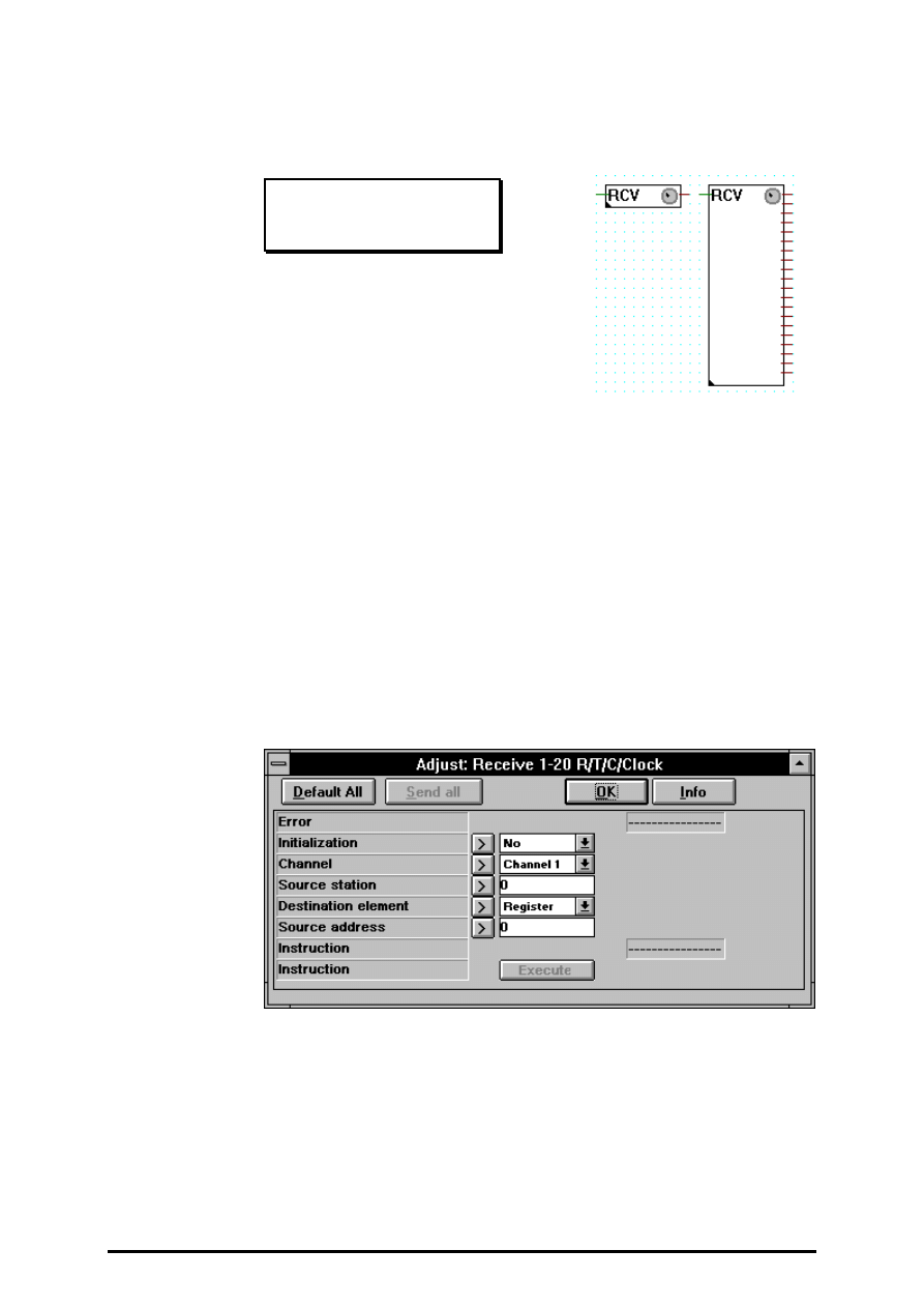
FUPLA and KOPLA functions
Serial communcations
26/749 E1
(P-4417-E.DOC)
SAIA AG
Page 4-155
4.4.17.4
Receive 1-20 Registes/Timers/Counters/Clock
Receive 1-20 R/T/C/Clock
[_comrxi]
Input:
−
Enable
binary format
Outputs:
= Values
integer format
If the Enable input = H (binary connection to the left of the function box),
the values (numeric elements = registers, timers, counters or the hardware
clock) are transferred from the partner station to the numeric elements in
this station. The elements in this station are defined by the connections on
the right-hand side of the function box.
The function can be extended from 1 up to 20 receive elements.
Additional settings, such as channel number, type of source element, etc.,
are made in the appropriate settings window.
Receive 1-20 R/T/C/Clock (detailed description)
This function can only be executed on a master PCD, which has been as-
signed with the SASI function in D or SBUS mode.

Serial communcations
FUPLA and KOPLA functions
Page 4-156
SAIA AG
(P-4417-E.DOC)
26/749 E1
The function permits from 1 up to 20 x numeric elements (R/T/C/Clock)
to be received from a slave station. Transmission takes place cyclically at
the maximum possible speed for as long as the active signal is high (input
"Send"). When the input receives a positive edge, at least one transmis-
sion takes place, even if the impulse is shorter than one communications
transmission cycle.
Potential sources of error:
Assignment missing: The channel selected has been assigned wrongly or
not at all (no SASI or invalid SASI). Assignment other than by the SASI
function is not allowed.
Not master: The channel has not been assigned as master.
STXM: An error has been identified during execution of the STXM in-
struction. This ought not to arise when the present function is used, unless
another routine also has access to this channel.
Diagnosics: A communications error has been identified. This can be ana-
lysed in detail using the diagnostic possibilities of the SASI function. The
analysis can also take place in "Debug" mode.
Step: The channel has been put into "Step" operation by the "Debug"
mode of the SASI function. Communication cannot take place until the
channel is put into "Run" again.
Parameters:
Initialization: This option allows transmission during PCD start up, even
when the binary active signal is low. This permits the elements of a slave
station to be initialized after a halt of the
master station.
Channel: Channel number to use.
Station: Number of the slave station to which data are or have been
transmitted. No significance in mode D.
Type and address: Base element address of the slave station where he
elements transferred are to be stored. When more than one element is
transferred, they are stored at subsequent addresses.
Two registers are always used for transmission of the hardware clock.
Transmission must be arranged accordingly.
The "Instruction" button allows a transmission to be executed, even when
the active signal is low.
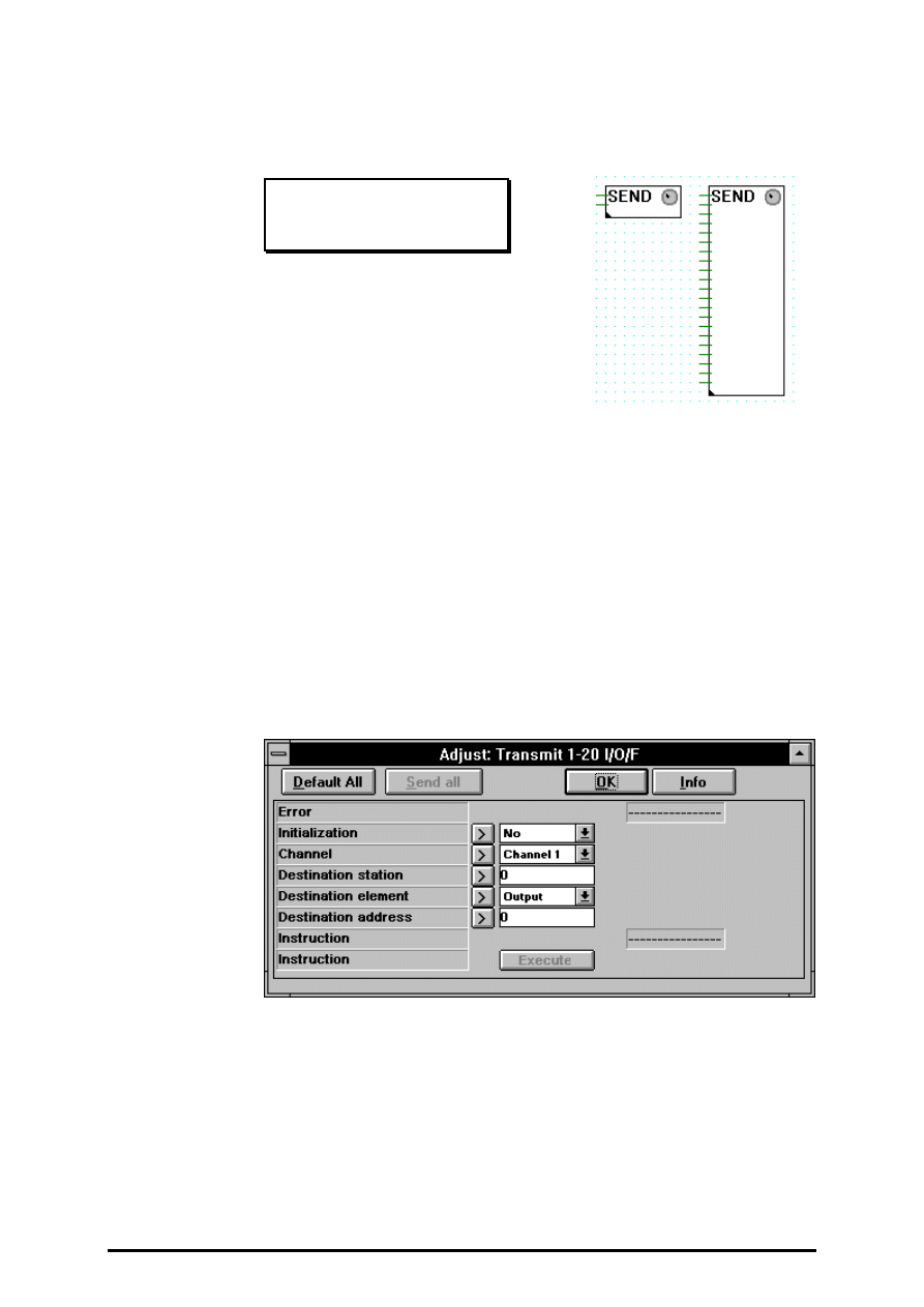
FUPLA and KOPLA functions
Serial communcations
26/749 E1
(P-4417-E.DOC)
SAIA AG
Page 4-157
4.4.17.5
Transmit 1-20 Inputs/Outputs/Flags
Transmit 1-20 I/O/F
[_comtxb]
Inputs:
−
Enable
binary format
−
Bit values
binary format
If the Enable input = H (binary connection at top left of the function box),
the data (boolean elements = inputs, outputs or flags) is transferred from
this station to a partner station. The elements in this station are defined by
the connections on the left-hand side of the function box (2nd to 21st
connection).
The function can be extended from 1 up to 20 transmit elements.
Additional settings, such as channel number, type of destination element,
etc., are made in the appropriate settings window.
Transmit 1-20 I/O/F (detailed description)
This function can only be executed on a master PCD, which has been as-
signed with the SASI function in D or SBUS mode.

Serial communcations
FUPLA and KOPLA functions
Page 4-158
SAIA AG
(P-4417-E.DOC)
26/749 E1
The function permits from 1 up to 20 x boolean elements (I/O/F) to be
sent to a slave station. Transmission takes place cyclically at the maximum
possible speed for as long as the active signal is high (input "Send").
When the input receives a positive edge, at least one transmission takes
place, even if the impulse is shorter than one communications transmission
cycle.
Potential sources of error:
Assignment missing: The channel selected has been assigned wrongly or
not at all (no SASI or invalid SASI). Assignment other than by the SASI
function is not allowed.
Not master: The channel has not been assigned as master.
STXM: An error has been identified during execution of the STXM in-
struction. This ought not to arise when the present function is used, unless
another routine also has access to this channel.
Diagnosics: A communications error has been identified. This can be ana-
lysed in detail using the diagnostic possibilities of the SASI function. The
analysis can also take place in "Debug" mode.
Step: The channel has been put into "Step" operation by the "Debug"
mode of the SASI function. Communication cannot take place until
the channel is put into "Run" again.
Parameters:
Initialization: This option allows transmission during PCD start
up, even when the binary active signal is low. This permits the
elements of a slave station to be initialized after a halt of the
master station.
Channel: Channel number to use.
Station: Number of the slave station to which data are or have been
transmitted. No significance in mode D.
Type and address: Base element address of the slave station where the
elements transferred are to be stored. When more than one element is
transferred, they are stored at subsequent addresses.
Two registers are always used for transmission of the hardware clock.
Transmission must be arranged accordingly.
The "Instruction" button allows a transmission to be executed, even when
the active signal is low.
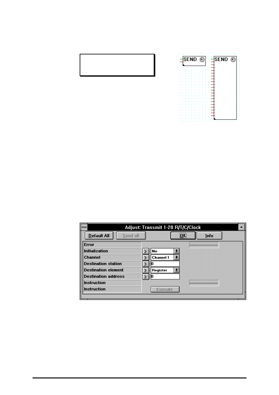
FUPLA and KOPLA functions
Serial communcations
26/749 E1
(P-4417-E.DOC)
SAIA AG
Page 4-159
4.4.17.6
Transmit 1-20 Registes/Timers/Counters/Clock
Transmit 1-20 R/T/C/Clock
[_comtxi]
Inputs:
−
Enable
binary format
= Values
integer format
If the Enable input = H (binary connection at top left of the function box),
the values (numeric elements = registers, timers, counters or the hardware
clock) are transferred from this station to a partner station. The elements
in this station are defined by the connections on the left-hand side of the
function box (2nd to 21st connection).
The function can be extended from 1 up to 20 transmit elements.
Additional settings, such as channel number, type of destination element,
etc., are made in the appropriate settings window.
Transmit 1-20 R/T/C/Clock (detailed description)
This function can only be executed on a master PCD, which has been as-
signed with the SASI function in D or SBUS mode.

Serial communcations
FUPLA and KOPLA functions
Page 4-160
SAIA AG
(P-4417-E.DOC)
26/749 E1
The function permits from 1 up to 20 x numeric elements (R/T/C/Clock)
to be sent to a slave station. Transmission takes place cyclically at the
maximum possible speed for as long as the active signal is high (input
"Send"). When the input receives a positive edge, at least one transmis-
sion takes place, even if the impulse is shorter than one communications
transmission cycle.
Potential sources of error:
Assignment missing: The channel selected has been assigned wrongly or
not at all (no SASI or invalid SASI). Assignment other than by the SASI
function is not allowed.
Not master: The channel has not been assigned as master.
STXM: An error has been identified during execution of the STXM in-
struction. This ought not to arise when the present function is used, unless
another routine also has access to this channel.
Diagnosics: A communications error has been identified. This can be ana-
lysed in detail using the diagnostic possibilities of the SASI function. The
analysis can also take place in "Debug" mode.
Step: The channel has been put into "Step" operation by the "Debug"
mode of the SASI function. Communication cannot take place until the
channel is put into "Run" again.
Parameters:
Initialization: This option allows transmission during PCD start up, even
when the binary active signal is low. This permits the elements of a slave
station to be initialized after a halt of the master station.
Channel: Channel number to use.
Station: Number of the slave station to which data are or have been
transmitted. No significance in mode D.
Type and address: Base element address of the slave station where the
elements transferred are to be stored. When more than one element is
transferred, they are stored at subsequent addresses.
Two registers are always used for transmission of the hardware clock.
Transmission must be arranged accordingly.
The "Instruction" button allows a transmission to be executed, even when
the active signal is low.
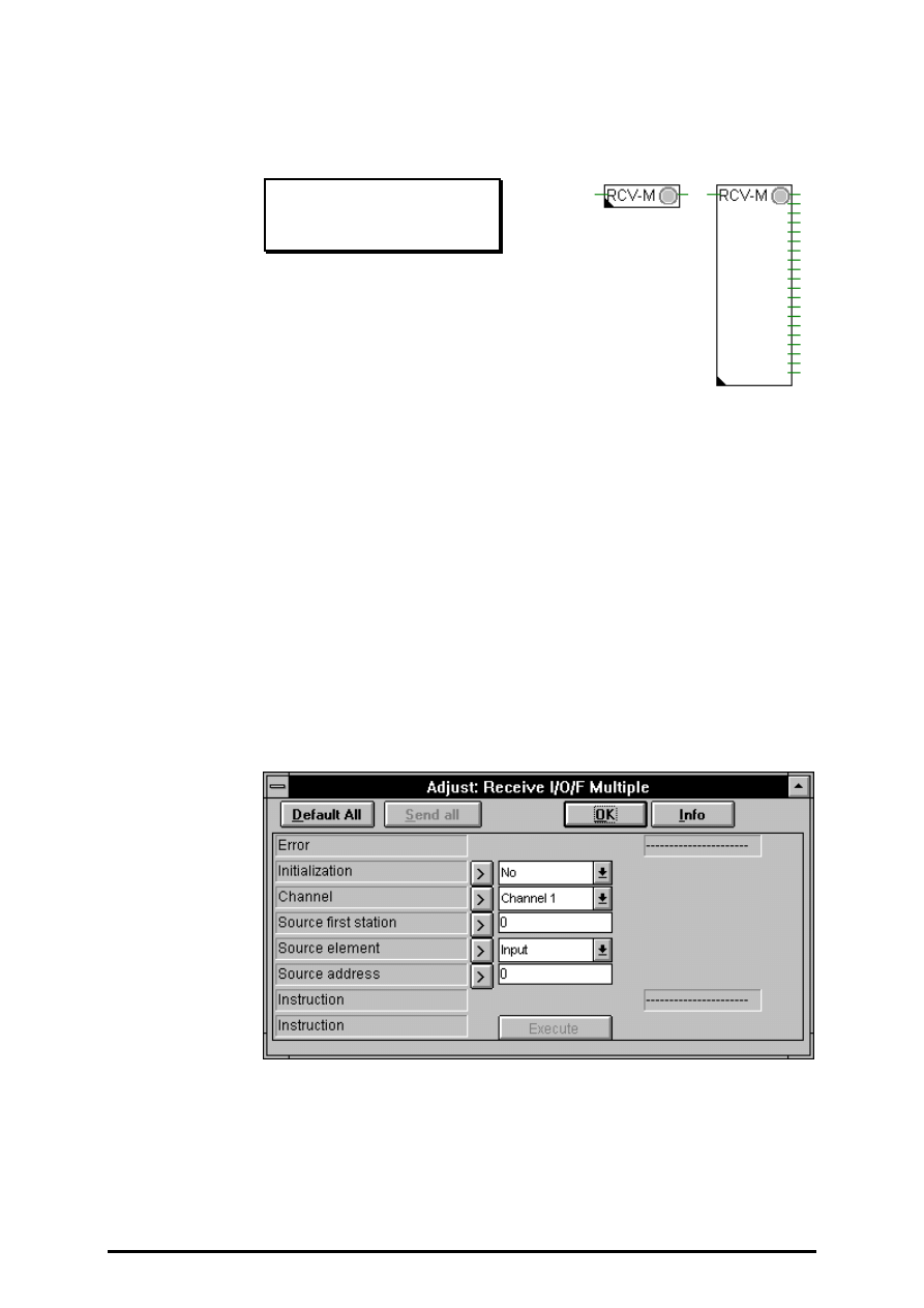
FUPLA and KOPLA functions
Serial communcations
26/749 E1
(P-4417-E.DOC)
SAIA AG
Page 4-161
4.4.17.7
Receive I/O/F from multiple stations
Receive I/O/F multiple
[_comrxbm]
Input:
−
Enable
binary format
Outputs:
−
Values
binary format
If the Enable input = H (binary input of the Fbox), one value (binary ele-
ments = Input, Output or Flag) is transferred from each partner station in
this station.
The function can be extended from 1 up to 20 output elements (one per
station). The size of the Fbox defines the number of stations to be read.
The first station is defined in the adjust window.
Additional settings, such as channel number, type of source element, etc.,
are made in the adjust window.
This function can only be executed on a master PCD, which has been as-
signed with the SASI function in S-BUS Master mode.

Serial communcations
FUPLA and KOPLA functions
Page 4-162
SAIA AG
(P-4417-E.DOC)
26/749 E1
The function permits to receive binary elements (I/O/F) from a number (1
up to 20) of successiv slave stations. Transmission takes place cyclically
at the maximum possible speed for as long as the active signal is high
(binary input). When the input receives a positive edge, at least one
transmission per station takes place, even if the impulse is shorter than
one communications transmission cycle.
Potential sources of error:
Assignment missing: The channel selected has been assigned wrongly or
not at all (no SASI or invalid SASI). Assignment other than by the SASI
function is not allowed.
Not master: The specified channel has not been assigned as master.
Not S-BUS: The specified channel is not assigned in S-BUS. Only the S-
BUS protocol can use this function.
SRXM: An error has been identified during execution of the SRXM in-
struction. This ought not to arise when the present function is used, unless
another routine also has access to this channel.
Diagnosics: A communications error has been identified. This can be ana-
lysed in detail using the diagnostic possibilities of the SASI function.
To big: The Fbox has been streched and so that the last station to be read
(first station plus strech index) is grather than 254. Only station number 0
to 254 are alowed for S-BUS Slaves.
Parameters:
Initialization: This option allows transmission during PCD start up, even
when the binary active signal is low. This permits the elements of a slave
station to be initialized after a halt of the master station.
Channel: Channel number to use.
Station: Number of the first slave station from which data are received.
Type and address: Element address of the slave station where the ele-
ments are to be received. One element per station is transfered.
The "Instruction" button allows a transmission to be executed, even when
the active signal is low.
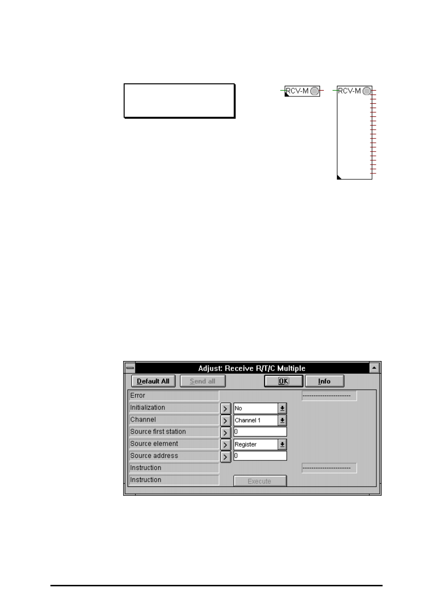
FUPLA and KOPLA functions
Serial communcations
26/749 E1
(P-4417-E.DOC)
SAIA AG
Page 4-163
4.4.17.8
Receive R/T/C from multiple stations
Receive R/T/C multiple
[_comrxim]
Input:
−
Enable
binary format
Outputs:
−
Values
integer format
If the Enable input = H (binary input of the Fbox), one value (numeric
element = Register, Timers or Counters) is transferred from each partner
station in this station.
The function can be extended from 1 up to 20 output elements (one per
station). The size of the Fbox defines the number of stations to be read.
The first station is defined in the adjust window.
Additional settings, such as channel number, type of source element, etc.,
are made in the adjust window.
This function can only be executed on a master PCD, which has been as-
signed with the SASI function in S-BUS Master mode.

Serial communcations
FUPLA and KOPLA functions
Page 4-164
SAIA AG
(P-4417-E.DOC)
26/749 E1
The function permits to receive numerics elements (R/T/C) from a number
(1 up to 20) of successiv slave stations. Transmission takes place cycli-
cally at the maximum possible speed for as long as the active signal is high
(binary input). When the input receives a positive edge, at least one
transmission per station takes place, even if the impulse is shorter than
one communications transmission cycle.
Potential sources of error:
Assignment missing: The channel selected has been assigned wrongly or
not at all (no SASI or invalid SASI). Assignment other than by the SASI
function is not allowed.
Not master: The specified channel has not been assigned as master.
Not S-BUS: The specified channel is not assigned in S-BUS. Only the S-
BUS protocol can use this function.
STXM: An error has been identified during execution of the STXM in-
struction. This ought not to arise when the present function is used, unless
another routine also has access to this channel.
Diagnosics: A communications error has been identified. This can be ana-
lysed in detail using the diagnostic possibilities of the SASI function.
To big: The Fbox has been streched and so that the last station to be read
(first station plus strech index) is grather than 254. Only station number 0
to 254 are alowed for S-BUS Slaves.
Parameters:
Initialization: This option allows transmission during PCD start up, even
when the binary active signal is low. This permits the elements of a slave
station to be initialized after a halt of the master station.
Channel: Channel number to use.
Station: Number of the first slave station from which data are received.
Type and address: Element address of the slave station where the ele-
ments are to be received. One element per station is transfered.
The "Instruction" button allows a transmission to be executed, even when
the active signal is low.
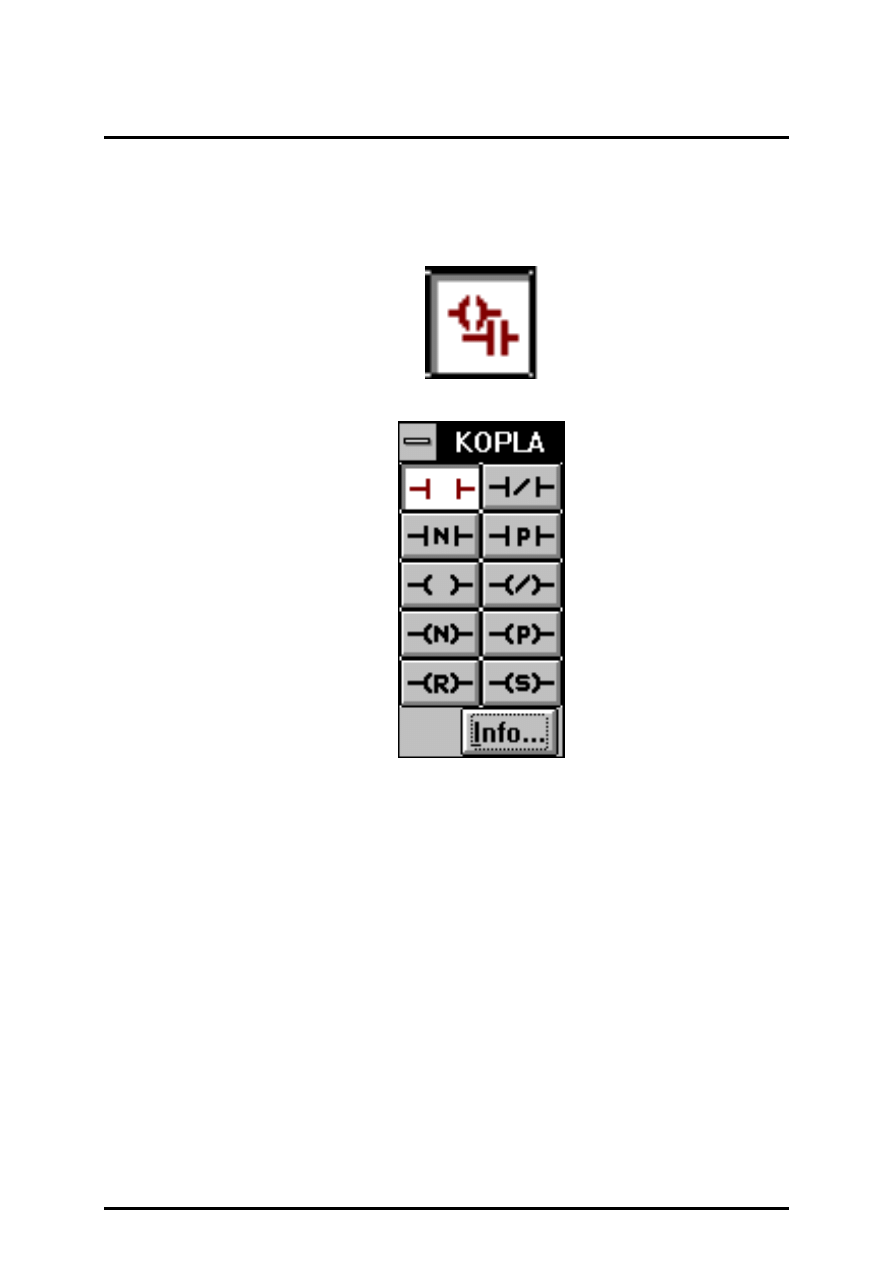
FUPLA and KOPLA functions
KOPLA (Ladder diagram)
26/749 E1
(P-4501-E.DOC)
SAIA AG
Page 4-165
4.5 The function families of the KOPLA (Ladder diagram)
The call of the KOPLA is done directly from the FUPLA toolbox and not
via the "FBox Selection" menu.
1
3
5
7
9
2
4
6
8
10
4.5.1
Contact
4.5.2
Contact closed
4.5.3
Contact negative
Negative edge
4.5.4
Contact positive
Positive edge
4.5.5
Coil
4.5.6
Coil closed
4.5.7
Coil negative
Negative edge
4.5.8
Coil positive
Positive edge
4.5.9
Coil reset
4.5.10
Coil set
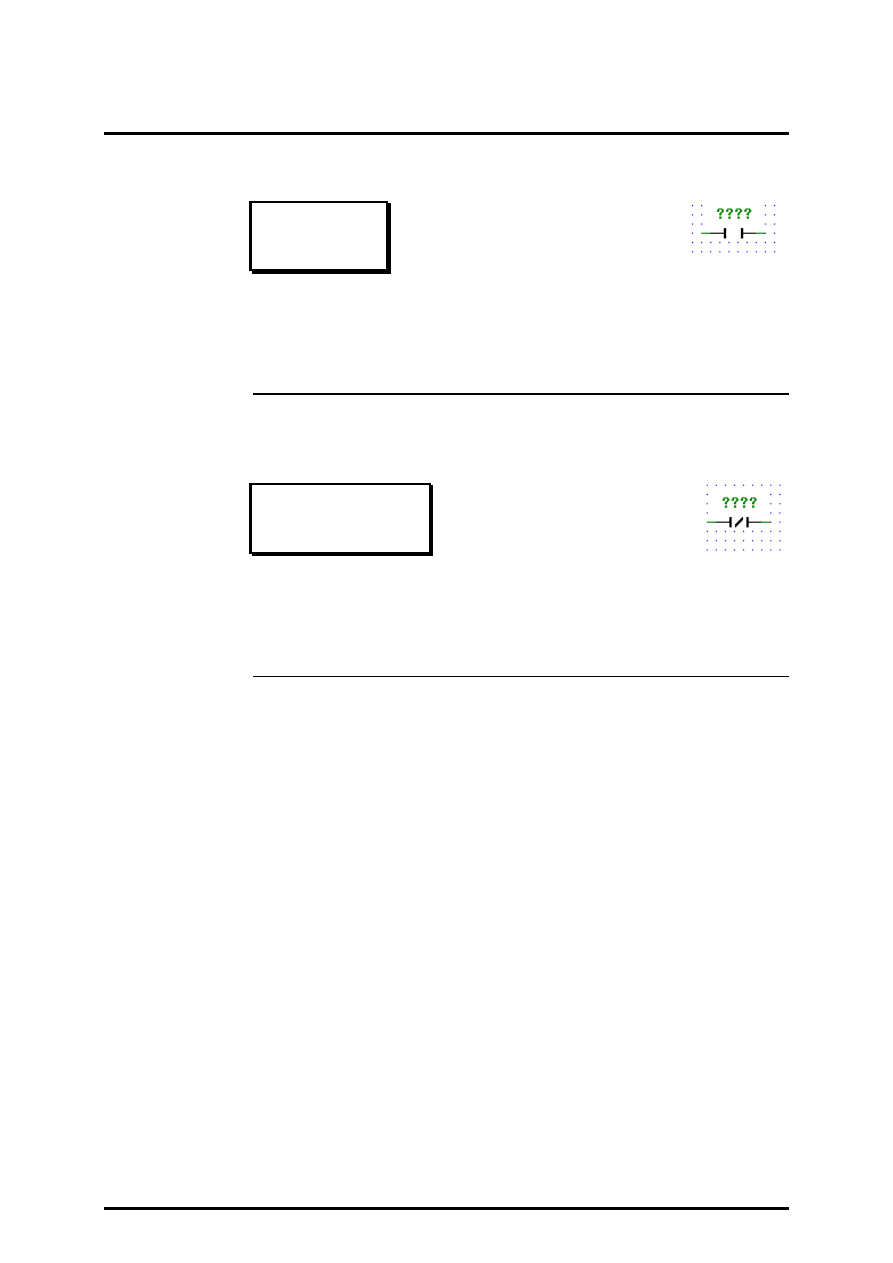
KOPLA (Ladder diagram)
FUPLA and KOPLA functions
Page 4-166
SAIA AG
(P-4501-E.DOC)
26/749 E1
KOPLA (Ladder diagram)
(sfupkopl)
4.5.1
Contact
Contact
[_contact]
Normally Open Contact: The state of the left link is copied to the right
link if the state of the associated Boolean variable is ON. Otherwise, the
state of the right link is OFF.
4.5.2
Contact closed
Contact closed
[_contactcl]
Normally Closed Contact: The state of the left link is copied to the right
link if the state of the associated Boolean variable is OFF. Otherwise, the
state of the right link is OFF.
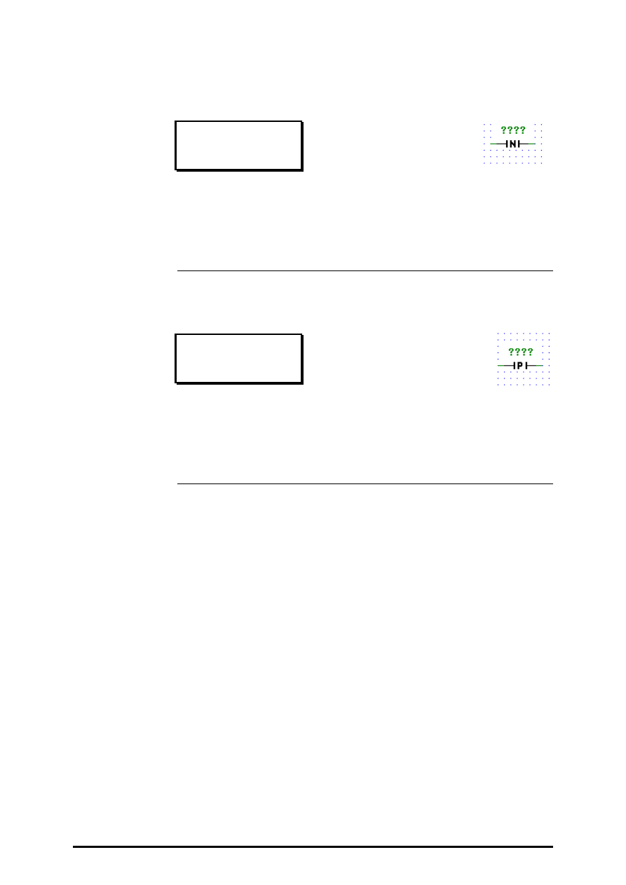
FUPLA and KOPLA functions
KOPLA (Ladder diagram)
26/749 E1
(P-4501-E.DOC)
SAIA AG
Page 4-167
4.5.3
Contact negative
Contact negative
[_contactnv]
Negative Transition-Sensing Contact: The state of the right link goes ON
when a transition of the associated variable from ON to OFF is sensed and
when the state of the left link is ON. The state of the right link shall be
OFF at all other time.
4.5.4
Contact positive
Contact positive
[_contactps]
Positive Transition-Sensing Contact: The state of the right link goes ON
when a transition of the associated variable from OFF to ON is sensed and
when the state of the left link is ON. The state of the right link shall be
OFF at all other time.
KOPLA (Ladder diagram)
FUPLA and KOPLA functions
Page 4-168
SAIA AG
(P-4501-E.DOC)
26/749 E1
4.5.5
Coil
Coil
[_coil]
Coil: The state of the left link is copied to the associated Boolean vari-
able and to the right link.
4.5.6
Coil closed
Coil closed
[_coilcl]
Negated Coil: The state of the left link is copied to the right link. The in-
verse of the state of the left link is copied to the associated Boolean vari-
able.
i.e. if the state of the left link is OFF, then the state of the associated vari-
able is set ON, and vice versa.
FUPLA and KOPLA functions
KOPLA (Ladder diagram)
26/749 E1
(P-4501-E.DOC)
SAIA AG
Page 4-169
4.5.7
Coil negative
Coil negative
[_coilnv]
Negative Transition-Sensing Element: The state of the associated Boolean
variable is ON from one evaluation of this element to the next when a
transition of the left link from ON to OFF is sensed. The state of the left
link is always copied to the right link.
4.5.8
Coil positive
Coil positive
[_coilps]
Positive Transition-Sensing Element: The state of the associated Boolean
variable is ON from one evaluation of this element to the next when a
transition of the left link from OFF to ON is sensed. The state of the left
link is always copied to the right link.
KOPLA (Ladder diagram)
FUPLA and KOPLA functions
Page 4-170
SAIA AG
(P-4501-E.DOC)
26/749 E1
4.5.9
Coil reset
Coil reset
[_coilreset]
RESET (Unlatch) Coil: The associated Boolean variable is set to the OFF
state when the left link is in the ON state, and remains reset until set by a
SET coil.
4.5.10
Coil set
Coil set
[_coilset]
SET (Latch) Coil: The associated Boolean variable is set to the ON state
when the left link is in the ON state, and remains set until reset by a
RESET coil.
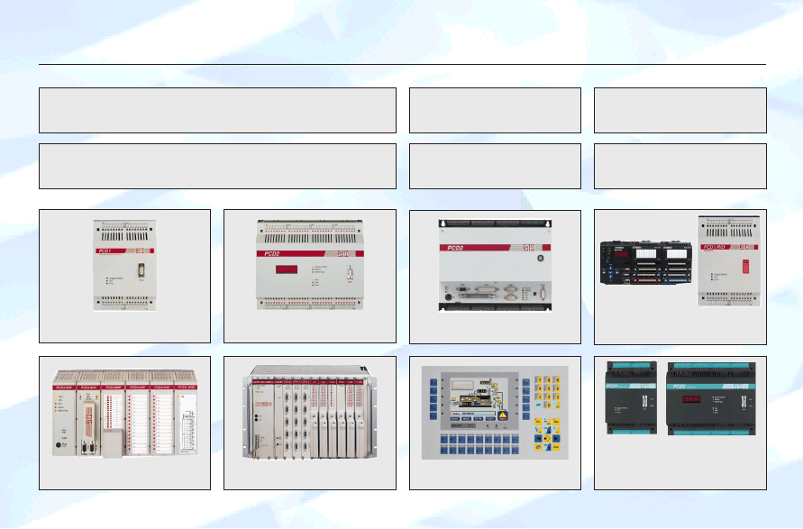
G³ówne menu
Document Outline
- Main menu
- Overview manuals
- Hauptmenü
- Übersicht der Handbücher
- Menu général
- Les manuels
- Menu generale
- Manuali
- Contents
- 4.4 The function families of the FUPLA
- Explanation of format and symbols
- 4.4.1 Binary functions [fupbina]
- 4.4.1.1 And 2-10 inputs
- 4.4.1.2 Or 2-10 inputs
- 4.4.1.3 Xor 2-10 inputs
- 4.4.1.4 Move
- 4.4.1.5 Dynamize
- 4.4.1.6 High
- 4.4.1.7 Low
- 4.4.1.8 Not connected
- 4.4.1.9 Multiplexer with binary selection
- 4.4.1.10 Multiplexer with integer selection
- 4.4.1.11 Demultiplexer with binary selection
- 4.4.1.12 Demultiplexer with integer selection
- 4.4.1.13 I/O indirect
- 4.4.1.14 Flag indirect
- 4.4.1.15 Even, 2-10 inputs
- 4.4.1.16 Odd, 2-10 inputs
- 4.4.2 Flip-Flops [sfupflip]
- 4.4.3 Counters [sfupcoun]
- 4.4.4 Time related functions [sfuptime]
- 4.4.5 Blinker [sfupblin]
- 4.4.6 Integer arithmetic [sfupinte]
- 4.4.6.1 Add
- 4.4.6.2 Subtract
- 4.4.6.3 Multiply
- 4.4.6.4 Divide
- 4.4.6.5 Square root
- 4.4.6.6 Average
- 4.4.6.7 Constant
- 4.4.6.8 Absolute
- 4.4.6.9 Bitwise and
- 4.4.6.10 Bitwise or
- 4.4.6.11 Bitwise exclusive or
- 4.4.6.12 Bitwise invert
- 4.4.6.13 Is equal to
- 4.4.6.14 Is greater or equal to
- 4.4.6.15 Is greater than
- 4.4.6.16 Is smaller or equal to
- 4.4.6.17 Is smaller than
- 4.4.6.18 Is zero
- 4.4.6.19 Limit
- 4.4.6.20 Maximum
- 4.4.6.21 Minimum
- 4.4.6.22 Move
- 4.4.6.23 Move when enabled
- 4.4.6.24 Move and store
- 4.4.6.25 Switch
- 4.4.6.26 Multiplexer with binary selection
- 4.4.6.27 Multiplexer with integer selection
- 4.4.6.28 Demultiplexer with binary selection
- 4.4.6.29 Demultiplexer with integer selection
- 4.4.6.30 Shift left
- 4.4.6.31 Shift right
- 4.4.6.32 Rotate left
- 4.4.6.33 Rotate right
- 4.4.6.34 Register indirect
- 4.4.6.35 T/C indirect
- 4.4.6.36 Not connected
- 4.4.7 Floating point arithmetic [sfupfloa]
- 4.4.7.1 Add
- 4.4.7.2 Subtract
- 4.4.7.3 Multiply
- 4.4.7.4 Divide
- 4.4.7.5 Square root
- 4.4.7.6 Average
- 4.4.7.7 Constant
- 4.4.7.8 Absolute
- 4.4.7.9 Sinus
- 4.4.7.10 Cosine
- 4.4.7.11 ARC tangent
- 4.4.7.12 Natural exponent
- 4.4.7.13 Natural log
- 4.4.7.14 Is equal to
- 4.4.7.15 Is greater or equal to
- 4.4.7.16 Is greater than
- 4.4.7.17 Is smaller or equal to
- 4.4.7.18 Is smaller than
- 4.4.7.19 Is zero
- 4.4.7.20 Limit
- 4.4.7.21 Maximum
- 4.4.7.22 Minimum
- 4.4.7.23 Move
- 4.4.7.24 Move when enabled
- 4.4.7.25 Move and store
- 4.4.7.26 Switch
- 4.4.7.27 Multiplexer with binary selection
- 4.4.7.28 Multiplexer with integer selection
- 4.4.7.29 Demultiplexer with binary selection
- 4.4.7.30 Demultiplexer with integer selection
- 4.4.7.31 Not connected
- 4.4.8 Converters (binary-integer-floating point) [sfupconv]
- 4.4.8.1 Binary to integer 1-8 I/O/F
- 4.4.8.2 Binary to integer 1-24 I/O/F
- 4.4.8.3 Binary to integer quick
- 4.4.8.4 Binary to integer reverse quick
- 4.4.8.5 Integer to binary 1-8 O/F
- 4.4.8.6 Integer to binary 1-24 O/F
- 4.4.8.7 Integer to binary quick
- 4.4.8.8 Integer to binary reverse quick
- 4.4.8.9 BCD to integer
- 4.4.8.10 BCD to integer quick
- 4.4.8.11 BCD to integer reverse quick
- 4.4.8.12 Integer to BCD
- 4.4.8.13 Integer to BCD quick
- 4.4.8.14 Integer to BCD reverse quick
- 4.4.8.15 1-bit to integer with shift
- 4.4.8.16 1-bit to integer LSB
- 4.4.8.17 Integer to 1-bit with shift
- 4.4.8.18 Integer LSB to 1-bit
- 4.4.8.19 Floating point format to integer format
- 4.4.8.20 Integer format to floating point format
- 4.4.9 Indirect addressing [sfupindi]
- 4.4.9.1 Copy to outputs
- 4.4.9.2 Read from inputs
- 4.4.9.3 Copy to flags
- 4.4.9.4 Read from flags
- 4.4.9.5 Copy to registers integer
- 4.4.9.6 Read from registers integer
- 4.4.9.7 Copy to registers float
- 4.4.9.8 Read from registers float
- 4.4.9.9 Copy toTimer/Counter
- 4.4.9.10 Read from Timer/Counter
- 4.4.9.11 Timer with indirect addressing.
- 4.4.9.12 Counter with indirect addressing
- 4.4.9.13 Read logic state from Timer/Counter
- 4.4.10 Move Data [sfupmove]
- 4.4.10.1 Move-In Bit
- 4.4.10.2 Move-Out Bit
- 4.4.10.3 Move-In Nibble (4 Bit binär)
- 4.4.10.4 Move-Out Nibble (4 Bit binär)
- 4.4.10.5 Move-In Digit (4 Bit BCD)
- 4.4.10.6 Move-Out Digit (4 Bit BCD)
- 4.4.10.7 Move-In Byte (8 Bit)
- 4.4.10.8 Move-Out Byte (8 Bit)
- 4.4.10.9 Move-In Word (16 Bit)
- 4.4.10.10 Move-Out Word (16 Bit)
- 4.4.11 Displays [sfupdisp]
- 4.4.12 GRAFTEC functions [sfupgraf]
- 4.4.13 Special functions [sfupspec]
- 4.4.14 Analog modules [sfupanlg]
- 4.4.14.1 Analog Input module PCD2.W1 (12 bit)
- 4.4.14.2 Analog Input module PCD2.W2 (8 Bit)
- 4.4.14.3 Analog Output module PCD2.W4 (8 Bit)
- 4.4.14.4 Analog Input/Output module PCD2.W5 (12 Bit)
- 4.4.14.5 Analog Input/Output module PCD4.W1 (12 Bit)
- 4.4.14.6 Analog Input module PCD4.W3 ( 12 Bit + Sign )
- 4.4.14.7 Analog Output module PCD4.W4 ( 8 Bit )
- 4.4.14.8 Analog Input / Output module PCD6.W1 ( 12 Bit )
- 4.4.14.9 Analog Input module PCD6.W3 ( 12 Bit + Siggn )
- 4.4.14.10 Analog Output module PCD6.W4 ( 8 Bit )
- 4.4.15 Regulation (PID control) [sfupregu]
- 4.4.16 User-defined functions [sfupuser]
- 4.4.17 Serial communications (mode "D") [sfupcomm]
- 4.4.17.1 Interface parameter assignment for a serial interface
- 4.4.17.2 Interface parameters external
- 4.4.17.3 Receive 1-20 Inputs/Outputs/Flags
- 4.4.17.4 Receive 1-20 Registes/Timers/Counters/Clock
- 4.4.17.5 Transmit 1-20 Inputs/Outputs/Flags
- 4.4.17.6 Transmit 1-20 Registes/Timers/Counters/Clock
- 4.4.17.7 Receive I/O/F from multiple stations
- 4.4.17.8 Receive R/T/C from multiple stations
- 4.5 The function families of the KOPLA (Ladder diagram) [sfupkopl]
- Demo version PG4
Wyszukiwarka
Podobne podstrony:
antropomotoryka 26 2004 id 6611 Nieznany (2)
26 33 id 31365 Nieznany (2)
Kolo E4 26 maj id 239780 Nieznany
26 en id 31374 Nieznany (2)
26 Wskazniki w C id 31425 Nieznany (2)
7 ZKM marzec 26 2012 id 45512 Nieznany
26 Wielkanoc id 31424 Nieznany
antropomotoryka 26 2004 id 6611 Nieznany (2)
26 33 id 31365 Nieznany (2)
3 26 id 32899 Nieznany (2)
I 26 id 208106 Nieznany
26 Ironia i groteska id 31313 Nieznany (2)
26 05 2011 id 31262 Nieznany (2)
26 4 id 31286 Nieznany (2)
Analiza 26 10 (Wyk ad) id 59803 Nieznany
Jezyk polski 26 id 222197 Nieznany
3 26 id 33450 Nieznany (2)
26 05 2014 Lechowski id 31340 Nieznany (2)
Laboratorium 3 IPP 26 id 261566 Nieznany
więcej podobnych podstron