Gas-Gleichdruckregler
Air/gas ratio controls
Régulateurs de proportion
GIK, GI
2.2.1.2 Edition 11.99 D/GB/F
2
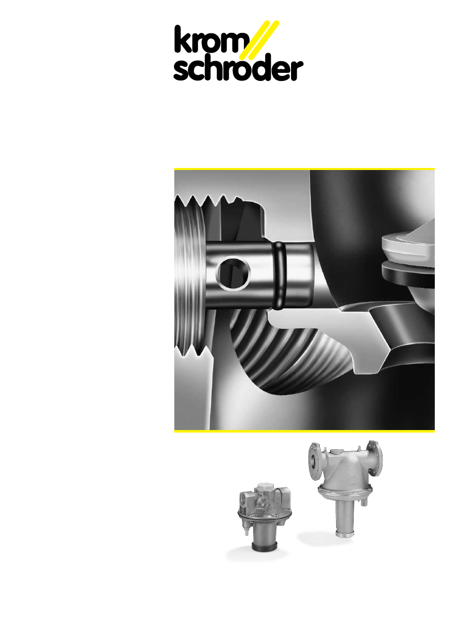
GIK
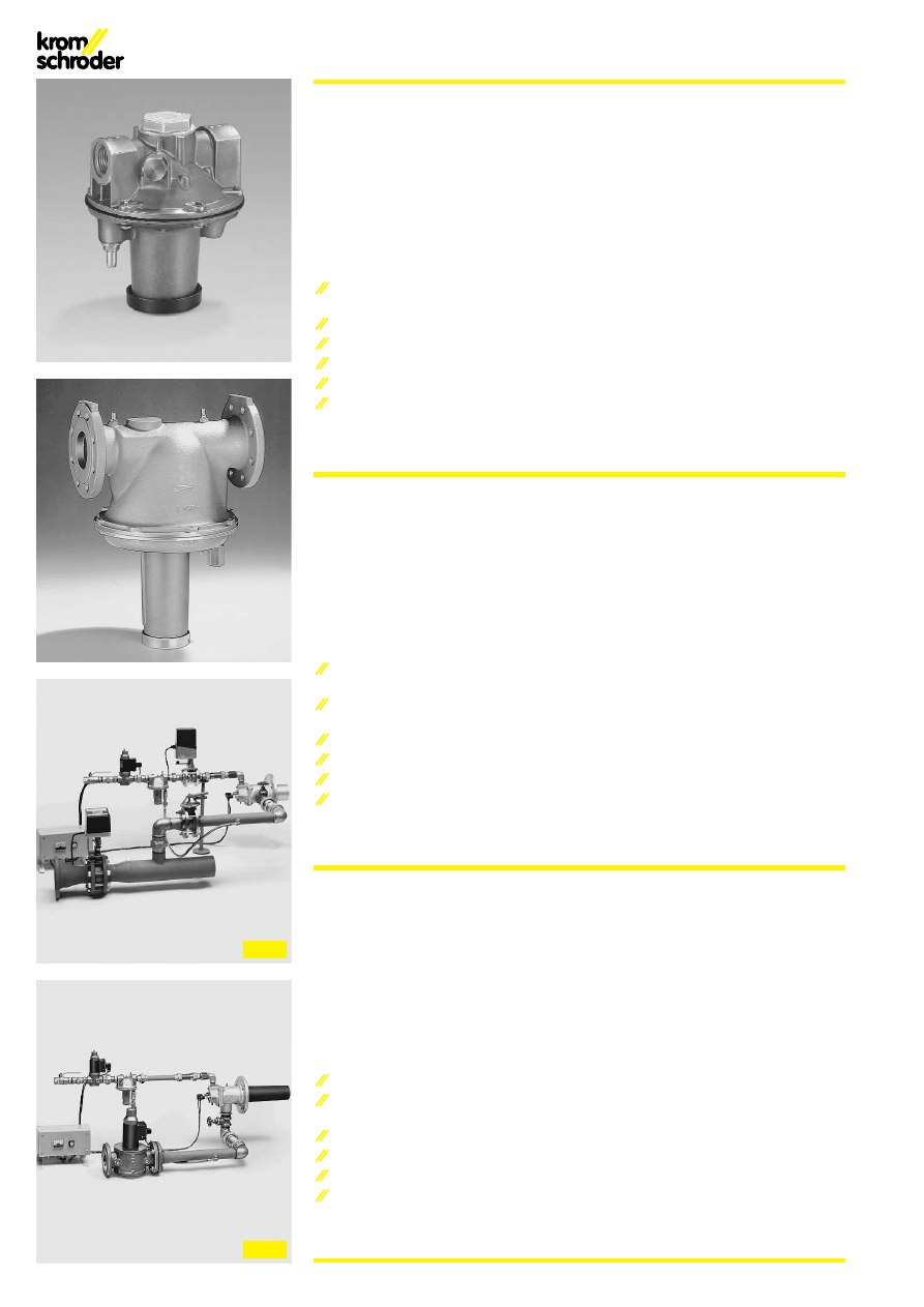
GI
Gas-Gleichdruckregler GIK, GI
Konstanthaltung des Gas-Luft-
Gemisches
Für stetige und stufige Brennerregelung
Hohe Regelgenauigkeit
Großer Regelbereich
Wartungsfrei
EG-Baumuster geprüft und zertifiziert
Anwendung
Die Gas-Gleichdruckregler GIK, GI dienen
zur Konstanthaltung des Gas-Luft-Verhält-
nisses und der Gasdruckregelung vor Gas-
brennern an Anlagen ohne vorgewärmte
Verbrennungsluft.
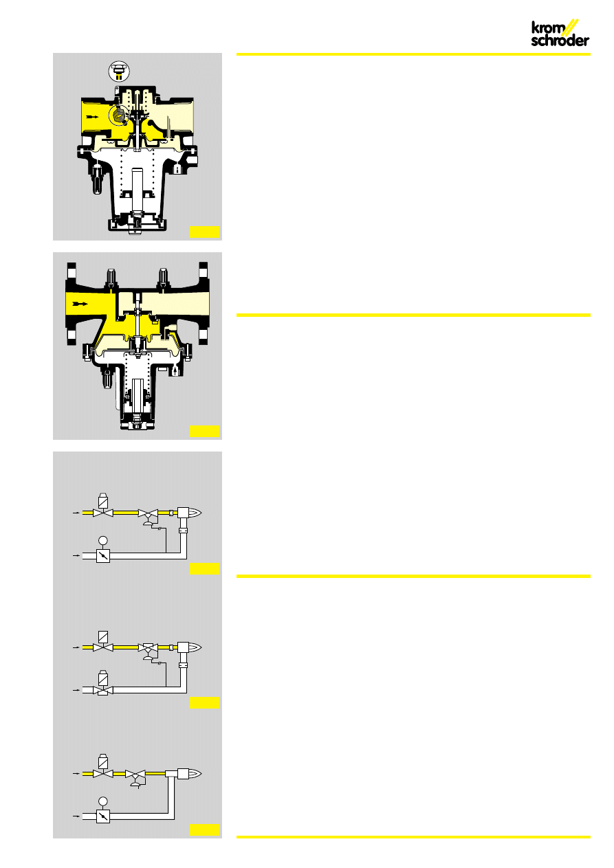
GIK, GI zur stetigen Regelung (Fig. 1),
GIK..B mit Bypaß für stufige Regelung
Groß-Klein-Aus (Fig. 2).
Nulldruckregelung mit Umbausatz (Fig. 7).
Die EN 746-2 verlangt, daß ein Brenner
immer mit einem stabilen Gas-Luft-
Gemisch gezündet wird. Diese Forderung
kann mit Hilfe des Gas-Gleichdruckreglers
erfüllt werden.
EG-Baumuster geprüft und zertifiziert nach
Gasgeräterichtlinie (90/396/EWG).
Air/gas ratio controls GIK, GI
For maintaining a constant air-gas
mixture
For continuous and step-by-step
burner control
High regulating precision
Wide regulating range
Maintenance-free
EC type-tested and certified
Application
The air/gas ratio controls GIK and GI serve
to maintain a constant air-gas ratio and to
regulate the gas pressure upstream of gas
burners on installations without preheated
combustion air.
GIK and GI for continuous control (Fig. 1),
GIK..B with bypass for high/low/off control
(Fig. 2).
Zero-pressure regulation with conversion
kit (Fig. 7).
EN 746-2 demands that a burner always be
ignited with a stable gas-air mixture. This
requirement can be met with the aid of the
air/gas ratio control.
EC type-tested and certified to the Gas
Appliance Directive (90/396/EEC).
Régulateurs de proportion
GIK, GI
Maintien constant du mélange gaz-air
Pour la régulation continue et étagée
des brûleurs
Grande précision
Vaste plage de réglage
Exempt de maintenance
Modèle CEE et certification
Application
Les régulateurs de proportion GIK et GI ser-
vent à maintenir constant le rapport gaz/air
ainsi qu’à assurer la régulation de la pression
de gaz en amont de brûleurs gaz dans des
installations sans air de combustion préchauf-
fé.
GIK et GI pour la régulation continue (Fig. 1),
GIK..B avec bypass pour la régulation
tout/peu/rien (Fig. 2).
Régulation à zéro avec jeu de modification (Fig. 7).
En vertu de la norme EN 746-2, un brûleur doit
impérativement être allumé avec un mélange
gaz-air stable. Le régulateur de proportion per-
met de satisfaire à cette prescription.
Modèle CEE et certification selon la directive
relative aux appareils à gaz (90/396/CEE).
Fig. 1
Fig. 2
3
GIK, GI
VG
GT
DKL
M
Stetige Regelung
Continuous control
Régulation continue
Fig. 4
Fig. 5
Fig. 6
Fig. 7
GIK..B
VG
VR
Stufige Regelung
Step-by-step control
Régulation étagée
GIK, GI
Venturi
VG..L
GT
DKL
M
Nulldruckregelung
Zero-pressure regulation
Régulation à zéro
Merkmale
– Der GIK kann in den GIK..B umgebaut
werden. Dazu wird die Bypaßschraube
ausgetauscht.
– Mit Feder zur Kompensation des
Meßwerkgewichts bei stetiger Regelung.
– Gas-Gleichdruckregler mit Vordruckaus-
gleichmembrane und Nullabschluß.
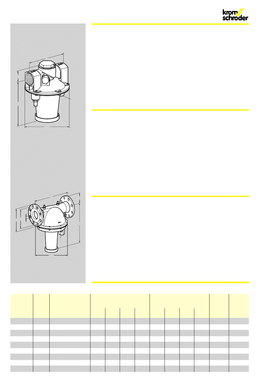
Funktion
(Fig. 3+4)
Der Gas-Gleichdruckregler wird vom Druck
der Luftleitung angesteuert. Er regelt den
Gasausgangsdruck p
a
im Verhältnis 1:1
zum Luft-Steuerdruck p
L
.
Die Brennerleistung wird mit Hilfe des Luft-
stellgliedes verändert. Ofendruckschwan-
kungen haben auf den Gas- und Luftdurch-
satz die gleiche Wirkung, so daß das
Gas-Luft-Gemisch nicht verändert wird.
Im Kleinlastbereich kann das Gas-Luft-
Gemisch durch Justieren der Reglerfeder
eingestellt werden. Bei stufiger Regelung ist
die Feder werksseitig so weit entspannt,
dass die Kleinlastmenge nur durch den
Bypaß strömt.
Die Einstellung bei Vollast erfolgt über Dros-
seln oder Hähne am Brenner.
Der GIK, GI für stetige Regelung durchfährt
einen großen Regelbereich (Fig. 5).
Der GIK..B schaltet um zwischen Klein- und
Großlast (Fig. 6).
Features
– The GIK can be converted to the GIK..B.
The bypass screw must be exchanged
for this purpose.
– With spring for compensating for the
weight of the metering assembly in the
case of continuous control.
– Air/gas ratio control with inlet pressure com-
pensation diaphragm and zero shut-off.
Function
(Figs. 3+4)
The air/gas ratio control is activated by the
pressure of the air line. It regulates the gas
outlet pressure p
a
in the ratio 1:1 to the air
control pressure p
L
.
The burner capacity is varied with the aid of
the air valve. Furnace pressure fluctuations
have the same effect on gas and air
throughput, thus meaning that the gas-air
mixture does not change.
In the min.-flow range, the gas-air mixture
can be set by adjusting the governor
spring. For step-by-step control, the
springs are relieved at the factory to ensure
that the low-fire rate volume only flows
through the bypass. The setting at high fire
is performed via restrictors or valves on the
burner.
The GIK, GI for continuous control covers a
wide regulating range (Fig. 5).
The GIK..B switches over between min.
flow and max. flow (Fig. 6).
Caractéristiques
– Le GIK peut être modifié en GIK..B. Il suffit
pour cela d’échanger la vis de bypass.
– Avec un ressort pour la compensation du
poids du système de mesure en régulation
continue.
– Régulateur de proportion équipé d’un dia-
phragme de compensation de la pression
amont et doté d’une étanchéité totale.
Fonctionnement
(Fig. 3+4)
Le régulateur de proportion est activé par la pres-
sion du conduit d’air. Il assure la régulation de la
pression de sortie de gaz p
a
selon le rapport 1:1
par rapport à la pression de commande d’air p
L
.
La puissance du brûleur est modifiée à l’aide
de l’organe de réglage d’air. Les variations de
la pression du foyer ont le même effet sur le
débit de gaz et d’air, de sorte qu’elles ne modi-
fient pas le mélange gaz-air.
En débit mini, le mélange gaz-air peut être
réglé grâce à un ajustement du ressort du
régulateur. En cas de régulage étagé, le ressort
doit être détendu en unsine de façon à ce que
seul ledébit minimum passe par le bypass. Le
réglage sur le débit maxi s’effectue à l’aide
d’obturateurs ou de robinets au niveau du
brûleur.
Les régulateurs GIK et GI pour régulation continue
conviennent à une vaste plage de réglage (Fig. 5).
Le GIK..B permet une commutation entre débit
mini et débit maxi (Fig. 6).
Fig. 3
H1
L
H2
øD
Rp
1
/
4
d2
k
D2
H2
øD
H1
L
Rp
3
/
8
Rp
1
/
2
4
Typ
DN
Anschluß
Abmessungen
Flansch
p
e max.
Gewicht
Type
Connection
Dimensions
Flange
Weight
Raccordement
Bride
Poids
L
H1
H2
ØD
D2
d2
k
Zahl
mm
mm
mm
mm
mm
mm
mm
No.
mbar
kg
GIK 15
15
Rp
1
/
2
120
34
132
134
-
-
-
-
200
1,0
GIK 20
20
Rp
3
/
4
125
34
132
134
-
-
-
-
200
1,1
GIK 25
25
Rp 1
125
34
132
134
-
-
-
-
200
1,1
GIK 40
40
Rp 1
1
/
2
155
45
149
185
-
-
-
-
200
1,8
GIK 50
50
Rp 2
200
52
167
234
-
-
-
-
200
2,8
GI 65
65
65
340
93
360
260
185
-
145
4
200
10,9
GI 80
80
80
380
100
420
310
200
18
160
8
200
15,7
GI 100
100
100
520
110
490
388
220
18
180
8
200
25
GI 150
150
150
600
143
513
520
285
23
240
8
200
48
Datentabelle / Specification table / Table de données
GIK
GI
Technische Daten
GIK
Gasart: Erdgas, Stadtgas, Flüssiggas (gas-
förmig), Biogas,
GIK..L nur für Luft.
Anschluß: Innengewinde nach ISO 7-1.
Luft-Steuerdruck p
L
: 0,5 bis 120 mbar.
Ausgangsdruck p
a
: 0,2 bis 119 mbar.
Differenzdruck zwischen Eingangsdruck p
e
und Ausgangsdruck p
a
: max. 100 mbar.
Übersetzungsverhältnis: 1:1.
Bypaßdurchmesser GIK..B:
Standard 1,5 mm
GIK..BZ: möglich von 0 bis 3,5 mm.
Einstellbereich bei Kleinlast: -3 bis +3 mbar.
Regelbereich: 10:1.
Anschluß für Steuerleitung: auf Rp 1/4.
Gehäuse: AlSi.
Membranen: NBR.
Ventilsitz: AlSi.
Ventilteller: Kunststoff.
Ventiltellerdichtung: NBR.
Bypaßschraube: Messing.
Umgebungstemperatur: -20 bis +70 °C.
Technical data
GIK
Type of gas: Natural gas, town gas, LPG
(gaseous), biologically produced methane,
GIK..L only for air.
Connection: Female thread to ISO 7-1.
Air control pressure p
L
: 0.5 to 120 mbar.
Outlet pressure p
a
: 0.2 to 119 mbar.
Differential pressure between inlet pressure
p
e
and outlet pressure p
a
: max. 100 mbar.
Transmission ratio: 1:1.
Bypass diameter GIK..B:
Standard 1.5 mm
GIK..BZ: possible from 0 to 3.5 mm.
Adjusting range at min. flow: -3 to +3 mbar.
Regulating range: 10:1.
Connection for control line: to Rp 1/4.
Housing: AlSi.
Diaphragms: NBR.
Valve seat: AlSi.
Valve disc: Plastic.
Valve disc seal: NBR.
Bypass screw: Brass.
Ambient temperature: -20 to +70°C.
Caractéristiques techniques
GIK
Type de gaz : gaz naturel, gaz de ville, GPL
(gazeux), biogaz,
GIK..L uniquement pour air.
Raccordement : taraudage selon ISO 7-1.
Pression de commande d’air p
L
: 0,5 à 120 mbars.
Pression de sortie p
a
: 0,2 à 119 mbars.
Pression différentielle entre pression d’entrée
p
e
et pression de sortie p
a
: max. 100 mbars.
Rapport de transformation : 1:1.
Diamètre du bypass GIK..B:
standard 1,5 mm
GIK..BZ : possible de 0 à 3,5 mm.
Plage d’ajustement débit mini : -3 à +3 mbars.
Plage de réglage : 10:1.
Raccordement pour ligne de commande :
à Rp 1/4.
Corps : AlSi.
Diaphragmes : NBR.
Siège : AlSi.
Clapet : matière plastique.
Joint de clapet : NBR.
Vis de bypass : laiton.
Température ambiante : -20 à +70°C.
5
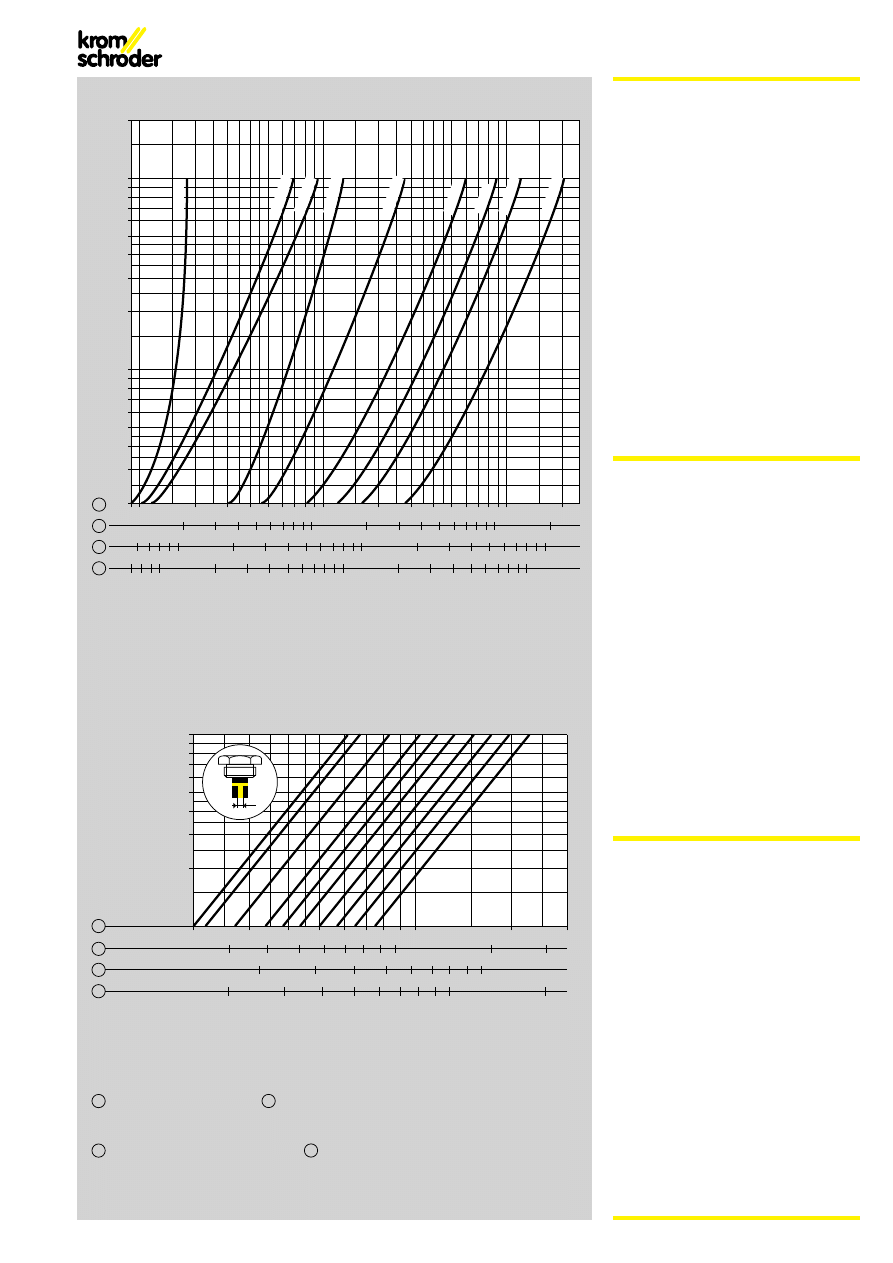
Druckgefälle · Pressure drop · Perte de charge dp [mbar]
2
3
4
5
6
8
10
20
30
40
50 60
80 100
200
300 400 500
1
20
30
40
50 60
80 100
200
300 400 500
2
7 8
10
20
30
40
50 60
80 100
200
300 400
4
6 7 8
10
20
30
40
50 60
80 100
2000
2000
800 1000
200
300
3
600
V' [m
3
/h (n)]
Volumenstrom / Flow rate / Caractéristiques de débit
600 800 1000
800 1000
500600 800 1000
400 500600
10
20
30
40
50
60
80
100
200
GIK 15
GIK 20
GIK 25
GIK 40
GIK 50
GI 65
GI 80
GI 100
GI 150
Eingangsdruck p
e
[mbar]
Inlet pressure
Pression amont
0,2
0,3
0,4
0,5
0,6
0,8
1
2
3
1
0,3
0,4
0,5
0,6
0,8
1
2
3
2
0,2
0,3
0,4
0,5
0,6
0,8
1
2
4
0,2
0,3
0,4
0,5
0,6
0,8
1
3
V'
[m
3
/h (n)]
1
2
4
3
= Erdgas
Natural gas
Gaz naturel
dv = 0,62
sg = 0.62
dv = 0,62
=
dv = 1,56
sg = 1.56
dv = 1,56
Stadtgas
Town gas
Gaz de ville
Flüssiggas
LPG
Gaz de pétrole liquéfié
=
dv = 0,45
sg = 0.45
dv = 0,45
=
dv = 1,00
sg = 1.00
dv = 1,00
Luft
Air
Air
10
20
30
40
50
60
80
100
1,5* 1,6
1,8
2,0 2,2 2,4 2,6 2,8 3,0 3,5
mm ø
ø
* Standard
Bypaßschraube / Bypass screw / Vis de bypass
GIK..B
GI
Gasart: Erdgas, Stadtgas, Flüssiggas (gas-
förmig), Biogas,
GI..L nur für Luft.
Anschluß: Flansch, PN 16 nach DIN 2501.
Luft-Steuerdruck p
L
: 0,5 bis 120 mbar.
Ausgangsdruck p
a
: 0,2 bis 119 mbar.
Differenzdruck zwischen Eingangsdruck p
e
und Ausgangsdruck p
a
: max. 100 mbar.
Übersetzungsverhältnis: 1:1.
Einstellbereich bei Kleinlast: -3 bis +3 mbar.
Regelbereich: 10:1.
Anschluß für Steuerleitung: Rp 1/2.
Gehäuse: AlSi.
Membranen: NBR.
Ventilsitz: AlSi.
Ventilteller: AlSi mit aufvulkanisierter
NBR-Dichtung.
Umgebungstemperatur: -15 bis +60° C.
GI
Type of gas: Natural gas, town gas, LPG
(gaseous), biologically produced methane,
GI..L only for air.
Connection: Flange, PN 16 to DIN 2501.
Air control pressure p
L
: 0.5 to 120 mbar.
Outlet pressure p
a
: 0.2 to 119 mbar.
Differential pressure between inlet pressure
p
e
and outlet pressure p
a
: max. 100 bar.
Transmission ratio: 1:1.
Adjusting range at min. flow: -3 to +3 mbar.
Regulating range: 10:1.
Connection for control line: Rp 1/2.
Housing: AlSi.
Diaphragms: NBR.
Valve seat: AlSi.
Valve disc: AlSi with vulcanised-on NBR seal.
Ambient temperature: -15 to +60°C.
GI
Type de gaz : gaz naturel, gaz de ville,
GPL (gazeux), biogaz,
GI..L uniquement pour air.
Raccordement : bride, PN 16 selon DIN 2501.
Pression de commande d’air p
L
: 0,5 à
120 mbars.
Pression de sortie p
a
: 0,2 à 119 mbars.
Pression différentielle entre pression d’entrée
p
e
et pression de sortie p
a
: max. 100 mbars.
Rapport de transformation : 1:1.
Plage d’ajustement débit mini : -3 à +3 mbars.
Plage de réglage : 10:1.
Raccordement pour ligne de commande :
Rp 1/2.
Corps : AlSi.
Diaphragmes : NBR.
Siège : AlSi.
Clapet : AlSi avec joint NBR vulcanisé.
Température ambiante : -15 à +60°C.
6
Fig. 8
Fig. 9
Fig. 10
-5 L* B* Z*
02
R
50
GIK
Typ/type GIK, GI
Nennweite
Nominal size
Diamètre nominal
Meßstutzen im Ausgang
Pressure test points in outlet
Prises de pression à la sortie
= 5
...im Eingang und Ausgang
...at inlet and outlet
...à l'entrée et la sortie
= 6
Bypaßschraube
Bypass screw
Vis de bypass
= B*
= Z*
Nur für Luft
Only for air
Uniquement pour air
= L*
15, 20, 25, 40, 50,
65, 80, 100, 150
Rp-Gewinde
Rp thread
Taraudage Rp
= R
Flansch
Flange
Bride
= F
Max. Eingangsdruck
Maximum inlet pressure
Pression d’entrée max.
pe 200 mbar = 02
Bypaßdurchmesser nach Kundenwunsch
Bypass diameter to customer specifications
Diamètre du bypass selon le souhait du client
* Wenn "ohne", entfällt dieser Buchstabe.
* If not applicable, this letter is omitted.
* Si non applicable, oublier cette lettre.
Typenschlüssel / Type code / Code de type
Kromschröder produziert umweltfreundlich.
Fordern Sie unseren Umweltbericht an.
Kromschröder uses environment-friendly production methods.
Please send away for our Environment Report.
Chez Kromschröder, la production respecte l’environnement.
Demandez notre rapport environnemental.
Technische Änderungen, die dem Fortschritt dienen, vorbehalten.
We reserve the right to make technical changes designed to improve our
products without prior notice.
Toutes les caractéristiques sont sujettes à modification
sans avis préalable.
R
F
02
-5 -6
L
B
Z
GIK 15..
V
–
V
V –
v
v
v
GIK 20..
V
–
V
V –
v
v
v
GIK 25..
V
–
V
V –
v
v
v
GIK 40..
V
–
V
V –
v
v
v
GIK 50..
V
–
V
V –
v
v
v
GI 65..
–
V
V
–
V
v
–
–
GI 80..
–
V
V
–
V
v
–
–
GI 100..
–
V
V
–
V
v
–
–
GI 150..
–
V
V
–
V
v
–
–
Bestellbeispiel / Example / Exemple
GIK 20R02-5BZ
Bei GIK..Z bitte den gewünschten Bypaßdurchmesser bei der Bestellung angeben.
On GIK..Z, please state the required bypass diameter when ordering.
Pour GIK..Z, prière d’indiquer le diamètre de bypass souhaité lors de la commande.
Auswahl / Selection / Choix
● Standard
●
●
Option
— nicht lieferbar / unavailable / non disponible
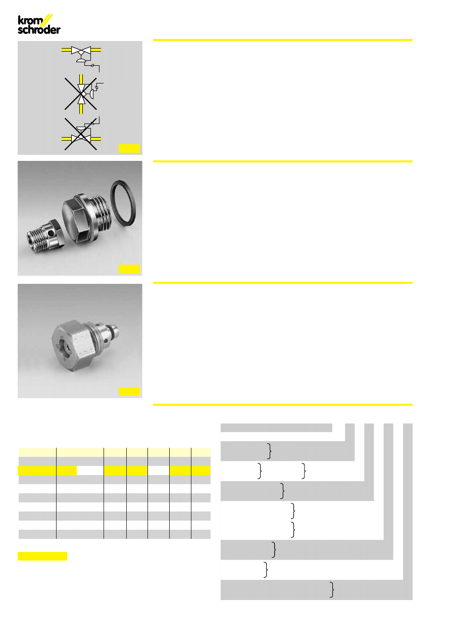
Einbau
Einbaulage: Der Federdom zeigt nach
unten (Fig. 8).
Beim GI zusätzlich eine externe Impulslei-
tung am Anschluß Rp 3/8 verlegen
(Abstand ca. 5xDN vom Reglerausgang).
Projektierungshinweise
Der Gaseingangsdruck p
e
muß immer
höher als der Luft-Steuerdruck p
L
sein,
damit der Gas-Gleichdruckregler nicht
übersteuert wird.
Vor dem Gas-Gleichdruckregler müssen
immer Sicherheitsventile eingesetzt wer-
den. Diese müssen bei stetiger Regelung
langsam öffnen.
Zubehör
Umbausatz für Nulldruckregelung (Fig. 9).
Variable Bypasschraube, einstellbar von
1,5 bis 3,5 mm (Fig. 10).
Installation
Fitting position: The spring dome points
downwards (Fig. 8).
On the GI, an external impulse line must
also be laid to connection Rp 3/8 (distance:
approx. 5 x DN from governor outlet).
Project planning information
The gas inlet pressure p
e
must always be
higher than the air control pressure p
L
so
that the air/gas ratio control is not over-
loaded.
Safety valves must always be installed
upstream of the air/gas ratio control. These
safety valves must open slowly in the case
of continuous control.
Accessories
Conversion kit for zero-pressure regulation
(Fig. 9).
Adjustable bypass screw, setting range:
1,5 to 3,5 mm (Fig. 10).
Montage
Position de montage : le dôme du ressort
doit être tête en bas (fig. 8).
Pour le GI, installer en supplément une ligne
d’impulsions externe au niveau du raccord
Rp 3/8 (distance : env. 5xDN à partir de la
sortie du régulateur).
Indications pour le bureau d’études
La pression d’entrée de gaz p
e
doit toujours
être plus élevée que la pression de com-
mande d’air p
L
pour que le régulateur de
proportion ne soit pas surmodulé.
Installer impérativement des vannes de
sécurité en amont du régulateur de propor-
tion. Ces vannes doivent être à ouverture
lente en régulation continue.
Accessoires
Jeu de modification pour régulation à zéro
(Fig. 9).
Bouchon de bypass variable, réglable de
1,5 à 3,5 mm (Fig. 10).
03250010 ep/ivd 11.99 7.000
G. Kromschröder AG
Tel. 05 41/12 14-0 · Fax 05 41/1 21 43 70
Postfach 2809
info@kromschroeder.com
D-49018 Osnabrück
www.kromschroeder.de
Wyszukiwarka
Podobne podstrony:
LsciA gi z wykL,adAlw id 10118 Nieznany
kn gik inz st 5 5 id 236836 Nieznany
GiK id 52864 Nieznany
gik mnu calkowanie id 190983 Nieznany
kn gik inz st 5 2 id 236833 Nieznany
cw8 gi dzienne fpmaslow id 1238 Nieznany
gi 10 id 190209 Nieznany
anal ci gi igrfunk2010 id 59474 Nieznany (2)
LsciA gi z wykL,adAlw id 10118 Nieznany
kn gik inz st 5 5 id 236836 Nieznany
Abolicja podatkowa id 50334 Nieznany (2)
4 LIDER MENEDZER id 37733 Nieznany (2)
katechezy MB id 233498 Nieznany
metro sciaga id 296943 Nieznany
perf id 354744 Nieznany
interbase id 92028 Nieznany
Mbaku id 289860 Nieznany
Probiotyki antybiotyki id 66316 Nieznany
miedziowanie cz 2 id 113259 Nieznany
więcej podobnych podstron