1 - 11
CCNP: Optimizing Converged Networks v5.0 - Lab 4-7
Copyright
© 2007, Cisco Systems, Inc
Lab 4.7 WAN QoS Tools
Learning Objectives
• Configure
Multilink
PPP
• Configure Multilink PPP Link Fragmentation and Interleaving
• Configure Generic Traffic Shaping
• Configure Committed Access Rate policing
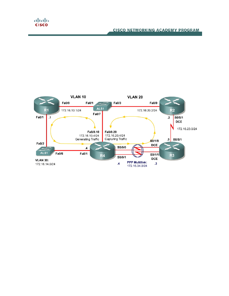
Topology Diagram
Scenario
In this lab, you will configure Generic Traffic Shaping (GTS) and Committed
Access Rate (CAR) policing over Wide Area Network (WAN) serial connections.
These tools are generally used on WAN connections to shape or police the
entire traffic flow exiting an interface.
In this scenario, you will also configure Multilink PPP and the Link
Fragmentation and Interleaving (LFI) feature.
Preparation
This lab relies on the Advanced Pagent Configuration which you should have
created in Lab 3.2: Preparing for QoS.
Prior to beginning this lab, configure R4 and the switch according to the
Advanced Pagent Configuration. You may easily accomplish this on R4 by
loading the advanced-ios.cfg file from flash memory into the NVRAM, and
reloading.

R4# copy flash:advanced-ios.cfg startup-config
Destination filename [startup-config]?
[OK]
2875 bytes copied in 1.456 secs (1975 bytes/sec)
R4# reload
Proceed with reload? [confirm]
On the switch, load the advanced.cfg file into NVRAM and reload the device.
ALS1# copy flash:advanced.cfg startup-config
Destination filename [startup-config]?
[OK]
2875 bytes copied in 1.456 secs (1975 bytes/sec)
ALS1# reload
Proceed with reload? [confirm]
Next, instruct TGN to load the advanced-tgn.cfg file. At the end of Step 1, you
will begin generating TGN traffic.
R4# tgn load-config advanced-tgn.cfg
Step 1: Configure the Physical Interfaces
Configure all of the physical interfaces shown in the diagram, except for the two
serial links between R3 and R4. You will configure these two serial links in Step
2.
Set the clock rate on the serial link between R2 and R3 to 64 kbps and use the
no shutdown command on all interfaces. Set the informational bandwidth
parameter appropriately on the R2-R3 serial interfaces.
R1(config)# interface fastethernet 0/0
R1(config-if)# ip address 172.16.10.1 255.255.255.0
R1(config-if)# no shutdown
R1(config-if)# interface fastethernet 0/1
R1(config-if)# ip address 172.16.14.1 255.255.255.0
R1(config-if)# no shutdown
R2(config)# interface serial 0/0/1
R2(config-if)# bandwidth 64
R2(config-if)# ip address 172.16.23.2 255.255.255.0
R2(config-if)# clockrate 64000
R2(config-if)# no shutdown
R2(config-if)# interface fastethernet 0/0
R2(config-if)# ip address 172.16.20.2 255.255.255.0
R2(config-if)# no shutdown
R3(config)# interface serial 0/0/1
R3(config-if)# bandwidth 64
R3(config-if)# ip address 172.16.23.3 255.255.255.0
R3(config-if)# no shutdown
R4(config)# interface fastethernet 0/1
R4(config-if)# ip address 172.16.14.4 255.255.255.0
R4(config-if)# no shutdown
2 - 11
CCNP: Optimizing Converged Networks v5.0 - Lab 4-7
Copyright
© 2007, Cisco Systems, Inc

Now that R4 can reach R1 172.16.10.1 address via ARP, begin generating
TGN traffic.
R4# tgn start
Step 2: Configure Multilink PPP
Multilink PPP is a PPP feature that allows multiple physical connections to be
logically bound together to make a logical link across underlying serial
connections encapsulated with PPP. The multilink PPP interface regards its
bandwidth as the aggregate of the individual PPP connections.
For this lab, use multilink PPP to aggregate the two serial links between R3 and
R4. They will be set up to be 64 kbps links individually, but their multilink logical
connection will be 128 kbps.
First, configure the physical interfaces, Serial 0/1/0 and Serial 0/1/1 on R3 and
Serial 0/0/0 and Serial 0/0/1 on R4. Set the clock rate on the DCE interfaces to
64 kbps and assign the informational bandwidth parameter appropriately. You
will notice later that the multilink interface’s informational bandwidth parameter
is the sum of the active physical interface bandwidths as calculated from the
individual bandwidth parameters.
Next, set up the interfaces to use PPP as the Layer 2 encapsulation with the
encapsulation ppp command. Enable PPP multilink on each interface with the
ppp multilink command and configure each interface to participate in PPP
multilink group 1 with the ppp multilink group number command. Bring up the
interfaces with the no shutdown command. Do not configure any IP addresses
on the physical interfaces since they will solely operate at Layer 2.
R3(config)# interface serial 0/1/0
R3(config-if)# clockrate 64000
R3(config-if)# bandwidth 64
R3(config-if)# encapsulation ppp
R3(config-if)# ppp multilink
R3(config-if)# ppp multilink group 1
R3(config-if)# no shutdown
R3(config-if)# interface serial 0/1/1
R3(config-if)# clockrate 64000
R3(config-if)# bandwidth 64
R3(config-if)# encapsulation ppp
R3(config-if)# ppp multilink
R3(config-if)# ppp multilink group 1
R3(config-if)# no shutdown
R4(config)# interface serial 0/0/0
R4(config-if)# bandwidth 64
R4(config-if)# encapsulation ppp
R4(config-if)# ppp multilink
R4(config-if)# ppp multilink group 1
R4(config-if)# no shutdown
R4(config-if)# interface serial 0/0/1
R4(config-if)# bandwidth 64
R4(config-if)# encapsulation ppp
3 - 11
CCNP: Optimizing Converged Networks v5.0 - Lab 4-7
Copyright
© 2007, Cisco Systems, Inc

R4(config-if)# ppp multilink
R4(config-if)# ppp multilink group 1
R4(config-if)# no shutdown
Issue the interface multilink number command in global configuration mode to
enter configuration mode for the multilink interface. Since you are using group
number 1, configure the multilink interface with number 1. Assign the IP
address shown in the diagram to the multilink interface.
R3(config)# interface multilink 1
R3(config-if)# ip address 172.16.34.3 255.255.255.0
R4(config)# interface multilink 1
R4(config-if)# ip address 172.16.34.4 255.255.255.0
Verify that you can ping across the link. If not, troubleshoot.
R3# ping 172.16.34.4
Type escape sequence to abort.
Sending 5, 100-byte ICMP Echos to 172.16.34.4, timeout is 2 seconds:
!!!!!
Success rate is 100 percent (5/5), round-trip min/avg/max = 16/18/20 ms
R4# ping 172.16.34.3
Type escape sequence to abort.
Sending 5, 100-byte ICMP Echos to 172.16.34.3, timeout is 2 seconds:
!!!!!
Success rate is 100 percent (5/5), round-trip min/avg/max = 16/18/20 ms
To look at PPP multilink statistics, use the PPP-specific command show ppp
multilink. The bandwidth shown in this output is the sum of the individual link
bandwidths. The output below varies slightly between the routers because they
are running different IOS versions.
R3# show ppp multilink
Multilink1, bundle name is R4
Endpoint discriminator is R4
Bundle up for 00:03:29, total bandwidth 128, load 1/255
Receive buffer limit 24000 bytes, frag timeout 1500 ms
0/0 fragments/bytes in reassembly list
0 lost fragments, 5 reordered
0/0 discarded fragments/bytes, 0 lost received
0x2C received sequence, 0x2D sent sequence
Member links: 2 active, 0 inactive (max not set, min not set)
Se0/1/0, since 00:26:36
Se0/1/1, since 00:26:22
No inactive multilink interfaces
R4# show ppp multilink
Multilink1
Bundle name: R3
Remote Endpoint Discriminator: [1] R3
Local Endpoint Discriminator: [1] R4
Bundle up for 00:03:35, total bandwidth 128, load 1/255
Receive buffer limit 24000 bytes, frag timeout 1500 ms
4 - 11
CCNP: Optimizing Converged Networks v5.0 - Lab 4-7
Copyright
© 2007, Cisco Systems, Inc

0/0 fragments/bytes in reassembly list
0 lost fragments, 1 reordered
0/0 discarded fragments/bytes, 0 lost received
0x2D received sequence, 0x2C sent sequence
Member links: 2 active, 0 inactive (max not set, min not set)
Se0/0/0, since 00:26:42
Se0/0/1, since 00:26:28
No inactive multilink interfaces
Issue the generic show interfaces interface command to view multilink
interface information. The bandwidth shown in this output is the aggregate of
the active serial interfaces that you have assigned to this multilink group.
R3# show interfaces multilink 1
Multilink1 is up, line protocol is up
Hardware is multilink group interface
Internet address is 172.16.34.3/24
MTU 1500 bytes, BW 128 Kbit, DLY 100000 usec,
reliability 255/255, txload 1/255, rxload 1/255
Encapsulation PPP, LCP Open, multilink Open
Open: IPCP, CDPCP, loopback not set
Keepalive set (10 sec)
DTR is pulsed for 2 seconds on reset
Last input 00:00:34, output never, output hang never
Last clearing of "show interface" counters 00:06:55
Input queue: 0/75/0/0 (size/max/drops/flushes); Total output drops: 0
Queueing strategy: fifo
Output queue: 0/40 (size/max)
5 minute input rate 0 bits/sec, 0 packets/sec
5 minute output rate 0 bits/sec, 0 packets/sec
28 packets input, 4168 bytes, 0 no buffer
Received 0 broadcasts, 0 runts, 0 giants, 0 throttles
0 input errors, 0 CRC, 0 frame, 0 overrun, 0 ignored, 0 abort
28 packets output, 4626 bytes, 0 underruns
0 output errors, 0 collisions, 1 interface resets
0 output buffer failures, 0 output buffers swapped out
0 carrier transitions
R4# show interfaces multilink 1
Multilink1 is up, line protocol is up
Hardware is multilink group interface
Internet address is 172.16.34.4/24
MTU 1500 bytes, BW 128 Kbit, DLY 100000 usec,
reliability 255/255, txload 1/255, rxload 1/255
Encapsulation PPP, LCP Open, multilink Open
Open: IPCP, CDPCP, loopback not set
Keepalive set (10 sec)
DTR is pulsed for 2 seconds on reset
Last input 00:00:33, output never, output hang never
Last clearing of "show interface" counters 00:07:38
Input queue: 0/75/0/0 (size/max/drops/flushes); Total output drops: 0
Queueing strategy: fifo
Output queue: 0/40 (size/max)
5 minute input rate 0 bits/sec, 0 packets/sec
5 minute output rate 0 bits/sec, 0 packets/sec
29 packets input, 4606 bytes, 0 no buffer
Received 0 broadcasts, 0 runts, 0 giants, 0 throttles
0 input errors, 0 CRC, 0 frame, 0 overrun, 0 ignored, 0 abort
29 packets output, 4846 bytes, 0 underruns
0 output errors, 0 collisions, 1 interface resets
0 output buffer failures, 0 output buffers swapped out
0 carrier transitions
5 - 11
CCNP: Optimizing Converged Networks v5.0 - Lab 4-7
Copyright
© 2007, Cisco Systems, Inc

Notice that the queuing strategy is first-in, first-out (FIFO) on the logical
interfaces. Normally, the default queuing strategy on a serial interface with the
same speed would be weighted fair queuing (WFQ).
What is another type of interface that would benefit from being bundled in PPP?
From a conceptual perspective, what other types of logical bundling can occur
in a network? Give at least two examples.
Step 3: Configure Multilink PPP LFI
Link Fragmentation and Interleaving (LFI) allows the interfaces to fragment
large packets down to a set amount in order to minimize the serialization delay
between the time high-priority packets enter the hardware queue (FIFO) and
the time they are sent. For instance, in voice applications, where delay and jitter
are the top quality of service considerations, it is important that voice packets
encounter minimal delay especially on low-speed serial interfaces where there
is a large serialization delay.
Once packets have been fragmented, the LFI mechanism must also allow
fragments of packets to be transmitted non-consecutively. For instance, voice
packets must be allowed to be sent between fragments of large packets.
Shut down the multilink interface to prevent link flapping while you configure
LFI. Next, change the queuing strategy on the multilink interface from FIFO to
weighted fair queuing (WFQ) with the fair-queue command in interface
configuration mode. Set the interleaving fragment delay with the ppp multilink
fragment delay milliseconds command. Reduce the maximum delay to 15 ms
from the default 30 ms. This delay setting controls the maximum size to which
packets must be fragmented, attempting to avoid negative results in delay-
sensitive applications.
Enable MLPPP interleaving with the ppp multilink interleave command.
Finally, bring the interface back up.
6 - 11
CCNP: Optimizing Converged Networks v5.0 - Lab 4-7
Copyright
© 2007, Cisco Systems, Inc

R3(config)# interface multilink 1
R3(config-if)# shutdown
R3(config-if)# fair-queue
R3(config-if)# ppp multilink fragment delay 15
R3(config-if)# ppp multilink interleave
R3(config-if)# no shutdown
R4(config)# interface multilink 1
R4(config-if)# shutdown
R4(config-if)# fair-queue
R4(config-if)# ppp multilink fragment delay 15
R4(config-if)# ppp multilink interleave
R4(config-if)# no shutdown
Issue the show ppp multilink command to view the LFI configuration.
R3# show ppp multilink
Multilink1, bundle name is R4
Endpoint discriminator is R4
Bundle up for 00:00:48, total bandwidth 128, load 1/255
Receive buffer limit 24000 bytes, frag timeout 1500 ms
Interleaving enabled
0/0 fragments/bytes in reassembly list
0 lost fragments, 3 reordered
0/0 discarded fragments/bytes, 0 lost received
0xA received sequence, 0xA sent sequence
Member links: 2 active, 0 inactive (max not set, min not set)
Se0/1/0, since 00:01:03, 120 weight, 112 frag size
Se0/1/1, since 00:01:03, 120 weight, 112 frag size
No inactive multilink interfaces
R4# show ppp multilink
Multilink1
Bundle name: R3
Remote Endpoint Discriminator: [1] R3
Local Endpoint Discriminator: [1] R4
Bundle up for 00:05:19, total bandwidth 128, load 1/255
Receive buffer limit 24000 bytes, frag timeout 1500 ms
Interleaving enabled
0/0 fragments/bytes in reassembly list
0 lost fragments, 6 reordered
0/0 discarded fragments/bytes, 0 lost received
0x19 received sequence, 0x19 sent sequence
Member links: 2 active, 0 inactive (max not set, min not set)
Se0/0/0, since 00:05:34, 120 weight, 112 frag size
Se0/0/1, since 00:05:34, 120 weight, 112 frag size
No inactive multilink interfaces
Step 4: Configure Routing
Establish adjacencies for routing with Open Shortest Path First (OSPF). Include
all connected subnets within the 172.16.0.0/16 major network for all four
routers.
R1(config)# router ospf 1
R1(config-router)# network 172.16.0.0 0.0.255.255 area 0
R2(config)# router ospf 1
R2(config-router)# network 172.16.0.0 0.0.255.255 area 0
7 - 11
CCNP: Optimizing Converged Networks v5.0 - Lab 4-7
Copyright
© 2007, Cisco Systems, Inc

R3(config)# router ospf 1
R3(config-router)# network 172.16.0.0 0.0.255.255 area 0
R4(config)# router ospf 1
R4(config-router)# network 172.16.0.0 0.0.255.255 area 0
Which interface does the adjacency between R3 and R4 form on?
Step 5: Configure Generic Traffic Shaping
In Lab 4.6: Class-based Marking, Shaping, and Policing, you configured traffic
shaping using the Modular QoS command-line (CLI) interface (MQC). Shaping
can be configured on a per-interface basis by the use of Generic Traffic
Shaping (GTS), which you will configure in this lab. Generic traffic shaping is
considered a legacy QoS feature. In most modern networks, you would use the
MQC version of traffic shaping instead. However, it is useful to configure GTS
both pedagogically as well as to demonstrate traffic shaping outside of the
MQC. All of the configuration for GTS can be accomplished with the use of the
traffic-shape command in interface configuration mode.
Imagine that R3 is owned by an ISP. You have added another 64 kbps serial
link from R3 to R4 to the multilink group. However, according to your traffic
contract, the ISP is only responsible to forward traffic from you at a committed
information rate (CIR) of 128 kbps over this PPP multilink interface. Any excess
traffic may be dropped by the ISP without warning.
Understanding that your excess traffic may be dropped, you wish to minimize
the effect any policing in the provider network by configuring traffic shaping at
the exit to your network, R4’s multilink PPP interface.
Configure traffic shaping on R4’s multilink interface towards R3 and shape the
flow of traffic to a rate of 128 kbps. Issue the traffic-shape rate rate command
in interface configuration mode. Set the rate argument to 128 kbps. The traffic
will be buffered in software by the traffic-shaping.
R4(config)# interface multilink 1
R4(config-if)# traffic-shape rate 128000
Verify traffic shaping with the show traffic-shape and show traffic-shape
statistics commands. The former command shows statically configured options
while the latter command displays dynamically captured statistics.
R4# show traffic-shape
8 - 11
CCNP: Optimizing Converged Networks v5.0 - Lab 4-7
Copyright
© 2007, Cisco Systems, Inc

Interface Mu1
Access Target Byte Sustain Excess Interval Increment Adapt
VC List Rate Limit bits/int bits/int (ms) (bytes) Active
- 128000 1984 7936 7936 62 992 -
R4# show traffic-shape statistics
Acc. Queue Packets Bytes Packets Bytes Shaping
I/F List Depth Delayed Delayed Active
Mu1 75 19524 7279630 19500 7272037 yes
Step 6: Configure Committed Access Rate Policing
Traffic policing is similar to shaping. The difference is, while shaping tries to
smooth out a traffic profile, policing merely forces the traffic to conform to a
certain rate, without buffering it. The picture below illustrates the difference
(taken from cisco.com).
Describe a situation in which you would use both traffic shaping and policing but
not on the same interface:
Like shaping, policing can be configured either using the MQC to configure
class-based policing or on a per-interface basis with Committed Access Rate
(CAR) policing. You configure CAR on an interface by setting a policing rate
with the rate-limit command.
Set R3’s Serial 0/0/1 interface to police egress traffic to 56 kbps with a normal
burst size of 1500 bytes and a maximum burst size of 4000 bytes. Issue the
rate-limit direction bps normal-burst maxmium-burst conform-action action
exceed-action action command. When packets conform to the policy, send
them by using the continue keyword. When packets do not, drop them.
This command may cause the Open Shortest Path First (OSPF) adjacency
between R2 and R3 to "flap" (go down and then back up) periodically, because
some of the OSPF hello packets get dropped through CAR, despite WFQ on
the interface.
R3(config)# interface serial 0/0/1
R3(config-if)# rate-limit output 56000 1500 4000 conform-action continue
exceed-action drop
Verify with the command show interfaces rate-limit.
R3# show interfaces rate-limit
Serial0/0/1
Output
matches: all traffic
params: 56000 bps, 1500 limit, 4000 extended limit
9 - 11
CCNP: Optimizing Converged Networks v5.0 - Lab 4-7
Copyright
© 2007, Cisco Systems, Inc

conformed 17433 packets, 5992721 bytes; action: continue
exceeded 14032 packets, 6137014 bytes; action: drop
last packet: 16ms ago, current burst: 2580 bytes
last cleared 00:14:27 ago, conformed 55000 bps, exceeded 56000 bps
Final Configurations
R1# show run
!
hostname R1
!
interface FastEthernet0/0
ip address 172.16.10.1 255.255.255.0
no shutdown
!
interface FastEthernet0/1
ip address 172.16.14.1 255.255.255.0
no shutdown
!
router ospf 1
network 172.16.0.0 0.0.255.255 area 0
!
end
R2# show run
!
hostname R2
!
interface FastEthernet0/0
ip address 172.16.20.2 255.255.255.0
no shutdown
!
interface Serial0/0/1
ip address 172.16.23.2 255.255.255.0
clock rate 64000
no shutdown
!
router ospf 1
network 172.16.0.0 0.0.255.255 area 0
!
end
R3# show run
!
hostname R3
!
interface Multilink1
ip address 172.16.34.3 255.255.255.0
fair-queue 64 16 0
ppp multilink
ppp multilink fragment delay 15
ppp multilink interleave
ppp multilink group 1
!
interface Serial0/0/1
ip address 172.16.23.3 255.255.255.0
rate-limit output 56000 1500 4000 conform-action continue exceed-action drop
no shutdown
!
interface Serial0/1/0
bandwidth 64
no ip address
10 - 11
CCNP: Optimizing Converged Networks v5.0 - Lab 4-7
Copyright
© 2007, Cisco Systems, Inc

encapsulation ppp
clock rate 64000
ppp multilink
ppp multilink group 1
no shutdown
!
interface Serial0/1/1
bandwidth 64
no ip address
encapsulation ppp
clock rate 64000
ppp multilink
ppp multilink group 1
no shutdown
!
router ospf 1
network 172.16.0.0 0.0.255.255 area 0
!
end
R4# show run
!
hostname R4
!
interface Multilink1
ip address 172.16.34.4 255.255.255.0
fair-queue 64 16 0
traffic-shape rate 128000 7936 7936 1000
ppp multilink
ppp multilink interleave
ppp multilink group 1
ppp multilink fragment delay 15
!
interface FastEthernet0/1
ip address 172.16.14.4 255.255.255.0
no shutdown
!
interface Serial0/0/0
bandwidth 64
no ip address
encapsulation ppp
ppp multilink
ppp multilink group 1
no shutdown
!
interface Serial0/0/1
bandwidth 64
no ip address
encapsulation ppp
ppp multilink
ppp multilink group 1
no shutdown
!
router ospf 1
network 172.16.0.0 0.0.255.255 area 0
!
end
11 - 11
CCNP: Optimizing Converged Networks v5.0 - Lab 4-7
Copyright
© 2007, Cisco Systems, Inc
Wyszukiwarka
Podobne podstrony:
CCNP4 lab 6 4 en
CCNP4 lab 4 9 en
CCNP4 lab 3 1 en
CCNP4 lab 4 8 en
CCNP4 lab 3 2 en
CCNP4 lab 3 3 en
CCNP4 lab 4 2 en
CCNP4 lab 4 6 en
CCNP4 lab 5 1 en
CCNP4 lab 2 1 en
CCNP4 lab 4 4 en
CCNP4 lab 4 3 en
CCNP4 lab 6 3 en
CCNP4 lab 4 5 en
CCNP4 lab 4 1 en
CCNP4 lab 6 5 en
CCNP4 lab 6 5 en
CCNP4 lab 6 1b en
CCNP4 lab 6 2b en
więcej podobnych podstron